Additive Manufacturing of tooling for low volume production of Fibre Reinforced Plastic
|
|
|
- Louisa Eaton
- 8 years ago
- Views:
Transcription


1 Additive Manufacturing of tooling for low volume production of Fibre Reinforced Plastic Master s thesis in Product Development and Production Engineering OSKAR ADAMSSON MATHIAS BERGFJORD Department of Product and Production Development CHALMERS UNIVERSITY OF TECHNOLOGY Gothenburg, Sweden 2014

2

3 Additive Manufacturing of tooling for low volume production of Fibre Reinforced Plastic A process analysis of a growing technology OSKAR ADAMSSON MATHIAS BERGFJORD Department of Product and Production Development CHALMERS UNIVERSITY OF TECHNOLOGY

4 Gothenburg, Sweden, 2014 Additive Manufacturing of tooling for low volume production of Fibre Reinforced Plastic A process analysis of a growing technology OSKAR ADAMSSON MATHIAS BERGFJORD OSKAR ADAMSSON, MATHIAS BERGFJORD, 2014 Department of Product and Production Development Chalmers University of Technology SE Gothenburg Sweden Telephone +46(0) Chalmers Reproservice Gothenburg, Sweden 2014
31-772 1000 Chalmers Reproservice Gothenburg,")
5 Preface This thesis was written due to the great many ideas gained during Chalmers Formula Student. Thanks to Chalmers and the people behind the project for providing this great opportunity. Thanks to our supervisor Hans Sjögren and our Examiner Johan Stahre at Chalmers for all support. Many thanks to Semcon and especially our supervisor Stefan Banér for hosting the project and giving support when needed. For invaluable help with data gathering, a big thanks to Cliff Produktion & Modell AB and Stratasys, Ltd. Huge thanks to Protech for supplying us with the intake part and design support. Thanks also to Hexagon Metrology for helping us with photo scanning of the same part. Thanks are also due to CarbiX for making the manufacturing of the CFRP intake possible and supplying the materials for it. Finally thanks also to Erik, Axel, and Henrik for making the writing of this thesis immensely more fun.

6 Abstract This report investigates the viability of using an Additive Manufacturing, AM, process for making Fibre Reinforced Plastic forming-tools in low volume production. The study starts by identifying the optimal additive manufacturing process for tooling to be Fused Deposition Modelling, FDM, which is then used for comparative analysis versus the reference. The reference is selected to be CNC milled polyurethane blocks. The study includes simulations of processing times and a cost and lead time calculation from CAD to finished tool. Simulations have also been done to analyse possible optimization of the tool design for additive manufacturing. The study also includes a case study of an engine air intake where several conventional tools can be replaced with one FDM manufactured tool. The results of the cost and lead time analysis is that additive manufacturing is competitive relative to a reference CNC process when the tools are of limited size. It is also concluded that the additive process is more environmentally sustainable and is cleaner and easier to integrate into a production system. The results from the cost and lead time analysis is used to develop a process selection application which can calculate an approximate cost and lead time for any given tool based on a few basic parameters. A photo scanning is conducted on AM manufactured parts to analyse the geometrical accuracy of the process. The results of this analysis are inconclusive with previous studies where greater accuracy has been observed. Knowledge about AM processes is identified as critical to create the best design. The experiences gained during the project are presented in the discussion chapter as a mean of information transfer since little information about the subject was found in the early stages of this project. The conclusion of the project is that FDM is a viable process for tooling of small parts. Based on current trends in the industry it is concluded that in a few years an updated analysis will be even more in favour of the additive process. Finally it is concluded that the most benefit of additive processes is only gained if it is considered and designed for from the start of product development.

7 Table of contents 1 Introduction Purpose Delimitations Research statements Theory Additive Manufacturing Polymerization Sintering and Melting Production performance Composites Fibre Reinforced Plastics Sandwich construction FRP Manufacturing Process FRP Tooling manufacturing Method Literature study Process comparison Case study Process comparison application AM Process Analysis AM Simulations Tests Geometrical accuracy analysis AM manufacturing possibilities CNC Process Analysis CNC Simulation Results AM Processes AM Process comparison Tests AM Simulations Case study Geometrical accuracy analysis... 36

8 4.2 CNC Simulations Process Comparison Tool performance Cost and Lead time Process selection application Discussion Additive Manufacturing Process comparison Case study Possibilities and limitations Sensitivity Analysis Conclusions Verification of research statements Further studies: Recommendations Bibliography Appendices... 59

9 Table of figures Figure 1: Slicer representation of divided layers (Source: Carl Hanser Verlag GmbH & Co. KG, Author: Gebhardt, Andreas.) 3 Figure 2: Laser-Stereolithography process schematic (Source: Carl Hanser Verlag GmbH & Co. KG, Author: Gebhardt, Andreas.) 5 Figure 3: Selective Laser Sintering process schematic (Source: Carl Hanser Verlag GmbH & Co. KG, Author: Gebhardt, Andreas.) 6 Figure 4: Fused Layer Modelling process schematic (Source: Carl Hanser Verlag GmbH & Co. KG, Author: Gebhardt, Andreas.) 7 Figure 5: Layer Laminate Manufacturing process schematic (Source: Carl Hanser Verlag GmbH & Co. KG, Author: Gebhardt, Andreas.) 8 Figure 6: Area to volume ratio for a cylinder shape (Source: Oxford University Press Inc., Author: McGrum, N. G.) 10 Figure 7: Volume fraction to tensile strength relationship (Source: Oxford University Press Inc., Author: McGrum, N. G.) 11 Figure 8: Section view of the bell mouth design 18 Figure 9: CFD boundary description 18 Figure 10: CAD of the designed soluble tool 19 Figure 11: Baseline models 21 Figure 12: Pre-processing software, Stratasys Insight (left), Repetier (right) 22 Figure 13: Photo scanning of plenum parts 23 Figure 14: Visualization of PUR-block covering a part surface for CNC Pre-processing 25 Figure 15: Settings for tooling data in Catia V5R19 26 Figure 16: Visualization of the steps in the CNC pre-processing 26 Figure 17: Visualization of the CNC Pre-processing 26 Figure 18: Test samples manufactured, printed horizontal (left), printed vertical (right) 28 Figure 19: Tool finished with 500 grit sandpaper (left) and the FRP laminate (right) 29 Figure 20: Printed feature test (left) and post-processed sample (right) 30 Figure 21: Core tool test after lamination 30 Figure 22: Curved core 31 Figure 23: CFD velocity vectors, old design (left), new design (right) 33 Figure 24: Joined intake tool 34 Figure 25: Case cost, and lead time results 35 Figure 26: Case cost distribution 35 Figure 27: 3D-scanned surfaces compared to Catia 36 Figure 28: Geometrical accuracy of case parts 36 Figure 29: Geometrical accuracy of Curved test 37 Figure 30: Coefficient of thermal expansion range for materials 38 Figure 31: Total cost for AM processing compared to CNC 39 Figure 32: Total lead time for AM processing compared to CNC 39 Figure 33: Example of output from Process Application 40 Figure 34: Chart with CNC Stock-preparation 40 Figure 35: Chart with CNC Processing time 41 Figure 36: Chart with AM Processing time 41 Figure 37: Chart with Surface finishing time 42 Figure 38: Weight comparison for AM and CNC tooling 44 Figure 39: Cost and lead time with respect to increased AM processing speed 51 Figure 40: Total effect of critical parameters (a) current situation (b) bulk material, increased speed and reduced monitoring of CNC 52
 6 Figure 4: Fused Layer Modelling process schematic (Source: Carl Hanser Verlag GmbH & Co. KG, Author: Gebhardt, Andreas.")
10 Table of tables Table 1: RAMPF Tooling cutting data for PUR-foam 25 Table 2: Decision matrix for AM Processes 27 Table 3: Tests performed in this thesis 28 Table 4: Tested feature sizes 29 Table 5: Software Calibration 31 Table 6: AM processing time with Repetier software 32 Table 7: Design optimizations 32 Table 8: CFD simulation data from Ansys Table 9: CNC processing time with Catia V5R19 37 Table 10: Material Comparison 38 Table 11: List of AM possibilities 47

11 Abbreviations 3D Three-Dimensional AM Additive Manufacturing (section 2.1) CAD Computer Aided Design CAM Computer Aided Manufacturing CFRP Carbon Fibre Reinforced Plastic (section 2.4) CFS Chalmers Formula Student CTE Coefficient of Thermal Expansion FDM Fused Deposition Modelling (section 2.1.2) FLM Fused Layer Modelling (section 2.1.2) FRP Fibre Reinforced Plastic (section 2.4) HDT Heat Deflection Temperature LCA Life Cycle Analysis LLM Layer Laminate Manufacturing MDF Medium Density Board PC Polycarbonate PLA Polylactic acid PUR Polyurethane (section 2.7) PVA Polyvinyl alcohol ROM Rule of Mixture SL Stereolithography (section 2.1.1) SLS Selective Laser Sintering (section 2.1.2) STL Standard Tessellation Language UV Ultraviolet VARTM Vacuum Assisted Resin Transfer Molding (section 2.6)
 PVA Polyvinyl alcohol ROM Rule of Mixture SL Stereolithography (section 2.1.1) SLS Selective Laser Sintering (section 2.1.2) STL Standard Tessellation Language UV Ultraviolet VARTM Vacuum Assisted Resin Transfer Molding (section 2.")
12

13 1 Introduction The idea of this thesis was formed from experiences gained during the Chalmers Formula Student, CFS, project Formula Student is one of the world s largest competitions for engineers where the goal is to design, build and compete with a small race car (Institution of Mechanical Engineers, 2013). A large part of the car consisted of carbon fibre reinforced plastic parts. It was found that some designs were held back due to limitations of the manufacturing tooling. Also the tool making process was found to be very time consuming and costly. Not only because large amounts of manual labour is needed but also since the machining of the tools requires specialised workshops adding lead time due to transports and transfer of information. A CNC workshop requires highly skilled personnel which add to the cost. Further, the material used is expensive and large quantities are removed in the machining. At the moment there is no possible way to reuse the material. These insights together with the resent explosion of the 3D printer consumer market led to the idea that Additive Manufacturing, from here on AM, could be a viable replacement process for this kind of tooling. Additive Manufacturing is more or less a hands-off process compared to CNC machining where a lot of monitoring is required. Additive Manufacturing also allows for making very complex shapes without compromising the cost. Initial study of the subject showed little or no material written about it. During Formula Student, Semcon hosted a lightweight seminar (Semcon, 2012). Semcon was contacted regarding this thesis and since they are highly involved with lightweight design and manufacturing they were interested in supporting this study. Semcon is also a member of LIGHTer arena initiative (Swerea, 2014) which makes research into lightweight designs even more interesting for them. The thesis was therefore carried out with Semcon s support at their facilities at Lindholmen. 1.1 Purpose The purpose of this thesis is to investigate Additive Manufacturing and the possibilities of using it for tooling purposes in production of fibre reinforced plastic. The main topic is to compare Additive manufactured tooling to conventional milled polyurethane tooling regarding costs and lead times. This is done by first identifying the best AM technique for manufacturing of tools and then comparing that technique to the reference tooling. Processing times for the comparison is simulated or estimated for each case. The conclusions from the comparison are used to create an application which can support an engineer with a method selection between additive manufactured and milled tools. Tests will be done when needed to support the comparison and reasoning. The thesis also aims to identify and structure design options made possible by using AM tooling and deliver conclusions on how these could innovate products and where further studies are needed. One major case study is done to investigate the design possibilities of fully utilizing AM possibilities. Finally the thesis also aims to answer the research questions stated in paragraph

14 1.2 Delimitations This study is limited to AM processes using plastic materials. The experiences gained in CFS were mostly for polyurethane plastic tools and therefore the comparison of interest is similar plastic materials. Material tests are not included in the scope of this study. Comparisons of physical properties have been deemed necessary to compare tooling performance. Tests done in this study does not aim to reach statistical significance. This is because of the time limitation of the project and the volatility of manufacturing processes. The statistical results in this thesis can therefore only be viewed as trends or indications. This project will not include a full LCA of any studied process or material. This is also due to the time limitation. However an estimation of sustainability will be included for all processes and materials considered in this project. Indirect tooling methods, explained in Theory 2.8, have not been studied in this thesis. However conclusions can be made from the performance of the direct tooling regarding how well AM would produce a good master for indirect tooling purposes. This project will limit investigations in AM core structures to only include cases where the structure also is used for forming of the composite. This is to limit the scope to tooling. 1.3 Research statements Some research statements were formed before the start of this project. Methods have been selected in order to verify these statements and thus they have been used to guide the study. All of these statements are verified in the conclusion chapter. 1. AM will decrease the lead time and cost for a part relative to the level of complexity, compared to standard subtractive methods. 2. AM Tooling will produce parts with equally good surface finish, tolerance and mechanical properties as CNC-manufactured tools. 3. AM will enable a more complex design which subtractive manufacturing and formative methods cannot produce without a multi-step process. 4. AM can produce a good master for use in an indirect tooling process. 5. Combining tooling with structural implementations, an optimized manufacturing process can be achieved which will result in a decrease in labour work and lead time. 6. Using sustainable thermoplastic material an overall decrease in the environmental impact can be achieved, regardless of AM method. 7. AM can innovate and optimise all areas of production and product development. 2

15 2 Theory This chapter includes the theory behind the concepts in this thesis. Primarily the theory chapter is intended to describe the Additive Manufacturing processes and Fibre reinforced plastic properties and manufacturing processes. The content of this chapter was formed from extensive literature studies explained in the method chapter. 2.1 Additive Manufacturing Additive Manufacturing (AM) originally called 3D Printing is a manufacturing process which possesses the ability to construct three-dimensional objects, with a large spectrum of appliances. (Gebhardt, 2011, p. 2) Additive Manufacturing is the third pillar, in addition to Subtractive Manufacturing and Formative Manufacturing, on which the manufacturing community rests. As its name applies, material is added in order to create a part and today this category mainly consist of Layer-based processes which uses data from a Computer Aided Design (CAD) software. Within the CADsystem the model is converted into a standard STL-format. This data is transported to the AM machine or separate slicer-software in which the model is divided into layers (see Figure 1) and converted to machine-specific code and thereafter it is ready for printing. Figure 1: Slicer representation of divided layers (Source: Carl Hanser Verlag GmbH & Co. KG, Author: Gebhardt, Andreas.) 3
 originally called 3D Printing is a manufacturing process which possesses the ability to construct three-dimensional objects, with a large spectrum")
16 2.1.1 Polymerization Polymerization (Photo-polymerization) is an additive manufacturing subgroup using UV-radiation to selectively solidify a liquid monomeric resin such as epoxy, acrylate or vinyl ether (Gebhardt, 2011, p. 34). Additional curing is often necessary if a partially solidification is made. Laser-Stereolithography (SL) The oldest of additive manufacturing process developed by 3D Systems, USA. (Gebhardt, 2011, p. 34) Stereolithography provides very good surface finish and high level of detail. An UV-laser is directed by the machine into a resin bath and oriented by the contour of the part (see Figure 2). The laser beam will partially solidify the resin by polymerization and depending on the reactivity and transparency of the resin a specified layer thickness will be achieved by configuring the power of the laser beam and the speed of which it travels over the resin. After the first layer is solidified the part and the build platform on which it rests will be lowered corresponding to the next layer height. A new coating of resin will be done to make sure that it is equally distributed. This process requires vipers and vacuum depositing mechanism in the machine due to the low viscosity of the resin. A new layer is processed on top of the old and the part will be constructed from the bottom an upwards. The resin bath in which the part is submerged is not able to carry any weight e.g. parts or details that is in need of supports will have to be sustained by extra added support of solidified resin. These support structures will often be generated by the slicer-software and will be in the same material as the part. In the removal of the support after the hardening the connection between part and support will be noticeable as small spots on the part surface. Due to that Stereolithography uses a process of partially solidification when manufacturing a part further hardening will be needed after the part is printed and cleaned. This post-curing is done in a UV-chamber which will completely cure the part. The part can be treated in a few ways such as sanding, polishing and varnishing. These steps are dependent on the part requirements and are not a required step in the Stereolithography process. The resins used in this process are divided into filled or unfilled resins. A filled resin, unlike unfilled, can be further customised by adding particles such as aluminium, glass or carbon to give other characteristics to the part. Unfilled resins have a relatively poor stability and heat properties. 4
 Stereolithography provides very good surface finish and high level of detail. An UV-laser is directed by the machine into a resin bath and oriented by the contour of the part (see Figure 2).")
 Polymer Printing / Polymer Jetting Polymer printing is process similar to an ordinary ink-printer, a nozzle ejects resin onto a build platform and simultaneously two UV-lights follows the nozzle")
17 Figure 2: Laser-Stereolithography process schematic (Source: Carl Hanser Verlag GmbH & Co. KG, Author: Gebhardt, Andreas.) Polymer Printing / Polymer Jetting Polymer printing is process similar to an ordinary ink-printer, a nozzle ejects resin onto a build platform and simultaneously two UV-lights follows the nozzle and hardens the resin through polymerisation. When a layer is printed the platform is moved downwards and the next layer is processed onto the previous. The layer height is mm (Gebhardt, 2011, p. 37) and will create a smooth surface. This process gives the opportunity of using different colours and/or more than one material in the same part, resulting in different material properties in the same part. Similar to Stereolithography the Polymer printing process is in need of extra support structure if the part has an overhang. This is created by a second set of nozzles with a specific support material. This structure is automatically generated during preprocessing. This material can in the post-processing stage be rinsed away with water or other solution and will not leave any trace on the part Sintering and Melting These processes describe the usage of melting and re-solidification of powder based materials, both polymer and metal, to achieve a part. Plastics are more preferred in the Sintering process while metals are more common in Melting. When thermoplastic polymers are used no build platform or support structure is needed due to the dense powder surrounding the part. This is theoretically the same for metals but due to potential warping of the part, supports and a platform is preferred and most commonly used. 5
 and will create a smooth surface.")
18 Selective Laser Sintering (SLS) Sintering processes use an enclosed build chamber, which is sealed and filled with an inert gas to prevent oxidation, where the powder is contained. (Gebhardt, 2011, pp ) A laser beam will travel over the powder and locally melt the material in each layer and the material will solidify by thermal conductivity to the rest of the powder bed (see Figure 3). When a layer is completed the whole powder bed will be lowered and new powder is added from a reservoir and rolled over the previous layer to be able to get an uniform surface. The sintered part will be manufactured from the bottom and upwards layer-by-layer, and when the laser has done the top layer of the part a couple of extra layers of powder are added to maintain the temperature in the part and allow a homogeneous cool down of the whole powder cake. This cool down period is time consuming and can be done in another chamber to be able to give access to a new part in the build chamber. The part surface and geometry is based on the powder used and the speed and diameter of the laser beam. The range of material that can be used in a sintering process is wide and covers all categories. Further customisation of the parts material and structural properties is possible by adding particles in the powder mixture such as glass, carbon or aluminium. Post-processing of sintered parts is needed to separate the part from the powder cake and possible supports. This is often done with sand blasting and brushing when plastic materials are used but metals need mechanical processing of the support. Depending on the powder size and material further treatment can be necessary such as infiltration of plastic parts due to porousness. Figure 3: Selective Laser Sintering process schematic (Source: Carl Hanser Verlag GmbH & Co. KG, Author: Gebhardt, Andreas.) 6

19 Extrusion Fused Layer Modelling (FLM) Fused Layer Modelling represents the additive process of using thin molten strings extracted onto a platform that layer-by-layer is producing a part. (Gebhardt, 2011, p. 45) The material used is mainly thermoplastic filaments which are melted through a heated nozzle onto a heated build platform (see Figure 4). The molten strings will solidify by thermic conductivity into the platform and other layers. The filament thickness and the nozzle diameter determine the layer height and thereby the resolution of the part and common filament diameters ranges from 0.1 mm to 0.25 mm. (Swift & Booker, 2013, p. 239) The deposition is made in the x-y direction and when a layer is complete the build platform is lowered correspondingly to the layer height and a new layer is started. If a part is in need of support these are either made of the same material as the rest of the part or, if the machine allows, a second nozzle with support material is used. Coloured plastic can be used to achieve a coloured part. Depending on how the supports are processed the post-process is different; if soluble supports are used these can be washed away, otherwise the support is mechanically removed. FLM is often called Fused Deposition Modelling (FDM) due to this being the first commercialised process in the genre created by the Canadian company Stratasys (Gebhardt, 2011, p. 45). Figure 4: Fused Layer Modelling process schematic (Source: Carl Hanser Verlag GmbH & Co. KG, Author: Gebhardt, Andreas.) Powder-Binder Bonding Three Dimensional Printing Powder-Binder Bonding is a technique resembling the SLS-process with a powder as the base material and a liquid binder that is added to selectively solidify the contour of each layer. (Gebhardt, 2011) Commercial names for methods are 3DP and Voxeljet. The difference between the sintering and Powder-Binder Bonding is that no shielding gas or preheated environment is needed and the laser is exchanged with the binder. The build chamber is containing the powder and a piston lower the platform with each consecutive layer and more powder is added to the top surface. Due to the powder encapsulating the part there is no need for support; this is true even for metals as a result of that the process works in room temperature (Swift & Booker, 2013). 7


20 The material range for this process is almost infinite (Gebhardt, 2011, p. 48) due to the binder customisation is abundant. Coloured binder can also be used to colourise the part. Depending on which machine being used in manufacturing of a part the postprocessing is different. The majority of machines need their constructed parts to undergo a thermal de-binding and sintering afterwards to achieve the final properties of the part. Others methods need infiltration of epoxy resin or wax to reach a functional part. Layer Laminate Manufacturing (LLM) By cutting out layers of thin foils and stacking them consecutively onto each other a layer-by-layer part develops through a Layer Laminate Manufacturing method. The foils can be made of metals, ceramics, plastics or paper (Gebhardt, 2011). These are cut and fixed together depending on the material used. The foils are drawn from a roll in the machine and fixed against the build platform (see Figure 5). A cutting tool thereafter cut along the contour of the current layer and prepares the fixing mechanic. When the cut foil is attached the waste foil is drawn away from the platform and simultaneously a new sheet of foil follows and is placed on the second layer. While the foil is replaced the platform is lowered corresponding to the foil thickness. Generally no extra post-processing is needed but a few parts need infiltration and varnishing to keep the sheets from de-laminating. Figure 5: Layer Laminate Manufacturing process schematic (Source: Carl Hanser Verlag GmbH & Co. KG, Author: Gebhardt, Andreas.) 8

21 2.2 Production performance The performance of a production system is measured in productivity which is the ratio between outputs to input to the system. This is dependent on the costs in the system. Cost for a product is divided between material, labour, energy and capital costs. For a process requiring advanced machines or a high degree of automation the capital costs can be high. For a process with a high level of customization as is common in low volume manufacturing, labour costs are often a driving factor. This means cost can be saved by increasing the level of automation in low volume production systems. Another factor that is important for a production systems performance is the lead time through the system. This can be at least as important as cutting costs since many companies are willing to pay extra for a quick delivery and high order flexibility. 2.3 Composites A composite material is defined as a material consisting of at least two different materials. The properties of the composite will be a blend of the included materials and it is possible to engineer the composite to desired physical or chemical properties. Engineered composited usually consists of a binder, also called matrix, material and a second reinforcing material. 2.4 Fibre Reinforced Plastics The trends in industry and products for lightweight solutions for products have pushed the interest of Fibre Reinforced Plastic, FRP, composites in the last years. The technology in itself is from the early 1900s but because of high costs it has been used mostly in low volume production of high-tech or sports products. New demands on energy efficiency and resulting requirement of lighter products have caused a need for utilizing the weight advantage of FRP. This also means that there is a need to improve FRP production processes since they are still far behind other processes regarding both speed and costs. As stated above FRP can deliver high stiffness and strength at a very low weight if proper design is used. FRP utilizes strong fibres bonded in a plastic matrix. Commonly used fibres going from cheap to expensive are, glass, carbon, and aramid. For lightweight construction carbon fibre, CFRP, are the most interesting since they have the highest stiffness to weight ratio. The plastic matrix is commonly a thermosetting plastic, the most common from cheap to expensive being polyester, vinylester, or epoxy. The thermosets are two component solutions which are mixed before application. Since thermosets are in liquid state at the application and then undergoes crosslinking and solidification they can conform to complex geometries in one forming step, like for example a complete boat hull. FRP works by distributing the forces on the composite from the matrix into the reinforcement. This means the composite is only as strong as the bond between the reinforcement and the matrix (N. G. McCrum, 1997). This means a high surface to volume ratio of the reinforcement is needed resulting in two possible shapes for the reinforcement, fibres and platelet, see Figure 6. Although platelets can be used in some applications, mostly fibres are used because of the better formability. In order to fully utilize the strength of the reinforcement the shear bond between fibre and matrix must be stronger than the fibre itself. If this is not the case the fibre will just 9
22 Figure 6: Area to volume ratio for a cylinder shape (Source: Oxford University Press Inc., Author: McGrum, N. G.) break loosed from the matrix resulting in failure of the matrix. This is described by the critical length, which is the length where the fibre will break at the same time as the matrix. Increasing the fibre length further from the critical length makes the FRP stronger by distributing the shear load in the matrix over a larger area. Continuous long fibres are therefore the best case scenario. Longer fibres are however more process demanding to form so shorter fibres are often used for convenience. As important for the strength of the FRP is the amount of fibres added to the matrix. This relation is described using the volume fraction of fibres in the FRP volume. As seen in Figure 7 the volume fraction of fibres, sigmaf, highly influences the strength of the composite. 10
23 Figure 7: Volume fraction to tensile strength relationship (Source: Oxford University Press Inc., Author: McGrum, N. G.) In the case of continuous unidirectional fibres this relation can be calculated using the Rule of Mixture (ROM). Equation I and II below describes the relation of FRP strength to fibre and matrix strength respectively. Equation I describe the case where load is applied in parallel with the fibres. Equation II describes the case where load is applied transverse to the fibres. As can be seen in these equations increasing the fibre volume fraction decreases the influence of the matrix strength for the total composite strength. In the transverse case the fibres have much less influence on the strength. ( ) ( ) Due to the anisotropy of FRP much care has to be taken when designing components. Especially in light constructions it is important to know the load case and engineer the fibre layout to the needs. This also places high demands on the manufacturing processes regarding applying the fibres as designed. Other problems that come from the manufacturing are inclusions of voids or small delamination in the composite. A high voids content reduces both static and fatigue strength. Generally a FRP laminate has to be below 5% in void content to be of acceptable quality (Sérgio Frascino Müller de Almeida, 1994) One problem with FRP laminates is the poor environmental sustainability. Since thermosetting plastics are used as matrix there in no way to recycle it. What can be done is to remove the matrix and reuse the fibres although this process in itself is not very sustainable. Thermoplastic matrices have better sustainability this way but 11
24 compromising the performance. Light technologies are really where FRP can compete sustainably with for example reduced fuel consumption over the lifetime of the product resulting in a better total sustainability for the product. Another issue with thermosets is the working environment. The contents of the resins are highly volatile. Precautions has to be taken and use of safety equipment is needed during the curing cycles and post processing. Dust from grinding of FRP components is also a safety hazard. 2.5 Sandwich construction Sandwich construction is the best way to fully utilize the potential of FRP laminates. By adding a core between two layers of laminate the bending strength and stiffness increases exponentially. Since the loads can be distributed over a large area on the core these can be made of very light materials giving all the benefits at a low weight cost. Commonly used core structures are balsa wood, foamed polymers, and metallic or polymeric honeycomb structures. Cores are provided in large sheets. For complex shapes machining are required to form the core. Foam cores can be shaped using heat although shrinkage of the core may occur. Honeycomb cores are best machined before it is expanded. 2.6 FRP Manufacturing Process FRP lamination processes for prototyping or short series is most likely to be a manual labour process. The process can be divided into two main categories, open or closed moulding. Open moulding being the use of one tool surface. Closed moulding being the use of two or more tool surfaces. Closed moulding requires more rigid tools in order to withstand the loads from the compression of the tools. Open moulding are for this reason cheaper and is preferred for use in prototyping or small series. The drawback being that only one side of the part will have a tooling surface. The most common manufacturing processes for small series are as stated before, manual operations of varying automation. The most basic process being Hand lay-up where fibres are laid out dry and resin is applied manually with the use of a brush or roller. Because of the manual resin application the fibre layout may be compromised during processing. Also it is a work against the clock to finish the layup before the resin starts to cure. The part is then left to cure as is. If a higher degree of consolidation is needed a bag is applied around the part and vacuum is used to put pressure down on the part. This assures that the fibres conform to the tool in areas where the geometry is more complex. The bag can be attached to the tool using a sticky sealing mass. For complex tools it is also possible to put the whole tool inside the bag. This is then called envelope bagging. Increasing the automation can be done using the VARTM (Vacuum Assisted Resin Transfer Moulding) process. In this process the resin is applied using vacuum. A mesh can be added on top of the fibres to allow the resin to flow over the part. If thick cut fibre mats are used this is not needed. For longer series the bag is often replaced by a formed silicone or plastic cover with integrated seals for vacuum and resin. This process can generate high fibre volume fractions. One drawback of this process is that sandwich panels cannot readily be manufactured in one step without using cut cores to still allow flow of resin to the inner laminate. Doing so increases the weight of the component significantly. Further increasing automation can be done using pre-preg fibres. These fibre weaves comes pre-impregnated with resin. The resin used in pre-preg 12
25 usually requires elevated temperatures to cure which puts additional demands on the tooling. The tape-like nature of pre-preg fibres makes them very easy to work with and allows for exact placement of fibres. Another process suitable for low volumes are filament winding. In this process fibres are wound onto a mandrel tool. The mandrel is able to rotate and a computer controlled arm stretches and moves the fibre application point. This process is useful when making tube-like structures. CNC control and only one internal tool is needed which makes the process suitable for low quantity production. Hand lay-up and VARTM processed FRP are commonly cured in room temperature. Depending on what resin is used the curing process can take everything from 30 minutes to over 24 hours. This is dependent on the reactivity of the resin. The limiting factor of how fast curing resin that can be used is the time needed in the process. The pot life, that is the time before the mixed resin starts to cure, decreases in the same way as the cure time with higher reactivity. Thus a slow process requiring a pot-life of two hours can require a cure time of 24 hours, (Huntsman, n.d.). In pre-preg weaves is common to use a resin with very long pot-life. Instead these resins require heat to start crosslinking. Usually a minimum of Celsius is needed to start the cure process, (SHD Composites, n.d.). 2.7 FRP Tooling manufacturing Production of fibre reinforced plastics products in short series or for prototype purpose demands a manufacturing tool, i.e. moulds. With current manufacturing processes this is generally solved with blocks of polyurethane or aluminium which is milled to desired shape. Further treatment is needed to fulfil the surface tolerances as well as facilitate the removal of parts from the moulds. This often requires specialized machinery which includes expensive and time consuming milling operations, of which a secondary effect is transportation to and from specialized workshops. The complexity of parts made of FRP composites with current manufacturing processes is limited by geometrical constraints such as release angles and outward facing surfaces in the moulds. These restrictions will for complex parts lead to, for example, divided female and male moulds or bellows when a seamless transition between halves is desired. This processes are very expensive and customized for each new part manufactured; often focusing on series production of the specific part. The type of tooling for low volume/prototyping FRP production, as described in the previous chapter, is most likely open tooling. Two different approaches exist here. The Direct-tooling approach where tool components are manufactured to be used as is. This is a machining operation with possible finishing, resulting in a final tool. The other approach is Indirect-tooling where a pattern is made in order to form the actual tool in a secondary process. The secondary operation is a casting or forming process which accurately depicts the pattern. This can be used to make tools of different materials then what is possible or viable to machine. Indirect-tooling can also allow for using the same pattern to create several tools. In low volume manufacturing the cost of the tooling is split on a low amount of parts. It is therefore even more important to keep tooling costs down. This means that metal tools are rarely used. There are many materials which can be used for cheaper tools. The common material to use is Polyurethane, PUR, foam. PUR are supplied in blocks and 13
26 offers good performance relative to the pricing, which is mainly based on the density. This material also offers good machinability which further reduces the processing cost. Higher density usually provides a smaller cell size meaning a higher surface finish is possible. The higher density material is also more resistant to denting and scratching of the surface. The blocks come in a few standard sizes and have to be cut and joined to make a stock part for machining. The blocks are then mounted on a MDF or FRP sandwich board to allow clamping in the machine without obstructing the machine tool. Joining of blocks and mounting to a board is done using adhesives. To cure pre-preg or increase the speed of curing in the other processes curing are done at elevated temperatures. This puts more demand on the tooling. It is important to take the thermal expansion of the tooling material into account. Compensating for tool expansion is necessary for large parts or where tolerances are high. Another issue is stress induced when the tooling expands more than the FRP. When high temperatures are needed it is common to use metal tools or to make a master plug of PUR which is then used for indirect tooling by making a FRP tool. 14
27 3 Method This thesis was carried out at Semcon in their facilities at Lindholmen, Sweden between 20 January and 10 June Data gathering has been an ongoing process throughout the project. Efforts have been made to structure the data in order to support a discussion about the subject. An initial screening of AM processes was done to identify one specific process to use for comparing with the reference CNC tooling process. The selected AM process and the reference CNC process have been compared regarding lead time and costs. Comparisons have also been made regarding tooling performance parameters such as surface finish, geometrical accuracy and thermal expansion. Practical tests have been carried out to verify functionality and to support the comparative analysis with data. An application supporting process selection between AM and CNC tooling has been developed. During the project ideas has been gathered with the intention of supporting further work and studies in the field. 3.1 Literature study The first part of this thesis was to conduct a literature study on the subject. This was done in order to further expand the knowledge of the thesis authors. Articles and written literature about Additive Manufacturing have been analysed and used as a knowledge base for the project. The information gathering has been a big part of the thesis and this is reflected in the theory chapter which explains the studied AM processes. FRP tooling manufacturing was also studied and has been explained in the theory chapter. It was also decided to include a brief FRP section in this thesis to explain the benefits in light weight construction and also its limitations. Information was gathered both from academic sources, such as the databases connected to Chalmers library system (Chalmers library 2014, databases), and also from internet sources. Since the topic of interest in this thesis is quickly developing most relevant information was attained through companies or reseller sources rather than academic sources. An investigation regarding patent in the area of Additive Manufacture was also conducted. The internal patent database at Chalmers University of Technology s library (Chalmers library 2014, patent database) and the Swedish Patent database was utilised for this (PRV 2014). 3.2 Process comparison The process comparison in this thesis includes a cost and lead time analysis. This has been made to include the tool manufacturing process from the pre-processing of the tool to a finished tool or master pattern. This way the analysis is limited from possible variations in design time and from the highly application dependent FRP manufacturing process. The analysis has been based on some of the tool models from Chalmers Formula Student Other included models are three models which were developed to get time simulations from Stratasys and one small model which was used in testing of a Makerbot. In total, ten models have been studied. Models have been used as is. This means no optimization of the geometry has been done when calculating the AM process. The time posts included in the analysis is; Setup, Processing time and Finishing operations. Cost has been calculated in Euros based on the conversion rate at the time, (Euroinvestor A/S, 2014). 15
28 Base data was collected to support the lead time and cost calculation. Wage cost was taken from the OECD stats database, (OECD, 2014). Material costs of /m 3 for the PUR material was provided by Cliff Produktion & Modell AB and based on their rates from the manufacturer RAMPF. Material costs for FDM was provided by Stratasys. The chosen material in the comparison analysis was PC plastic at /m 3. Stratasys also provided the amortization costs for their machines. Those costs were based on a utilization of 60 %. The amortization cost was validated against a price suggestion from a reseller (Aniwaa, 2014). CNC machine cost was based on values from Cliff Produktion & Modell AB. Since the study mainly is aimed at smaller parts; the smallest machine, a Famu Aktive Five 2000, in the workshop was used as reference. Mats Johansson at Cliff Produktion & Modell AB estimates a utilization of 50 % in their machine park and this was used to calculate amortization costs based on five year depreciation. Further costs can be seen in Appendix D. Average setup times for the processes were estimated based on experience and discussions. The setup times used in the calculation was 15 min for AM and 60 min for CNC. The time required to prepare the stock material for the CNC process was estimated for each part. The estimation is based on experiences and starts from a minimum of three hours, adding time for larger parts if additional cutting is required. The minimum time includes cutting of block and board, positioning, worker movements, and the adhesive joining process. Since the block building process includes an adhesive operation with long cure times, see theory, the lead time of the process has been estimated to always take at least 24h. The cost for the lead time is however only calculated on the actual working hours. A similar estimation as were done for setup times were done for the surface finishing operation. This process takes into account sanding of the tool and the release coating. When this process is done the tool is ready for layup of the part. The finishing times for the PUR tools where estimated based on experience from manufacturing the Formula Student tools. Experience was gained during the thesis work for finishing of AM parts. Based on the small test part and the case study of the plenum it was concluded that sanding of the AM tools was more time demanding then their PUR counterparts due to the harder material. There is also often some kind of support material which has to be removed. This knowledge resulted in an estimate of 50% more finishing time for AM tools than their PUR counterpart. No transport times have been included in the analysis other than some movement of the worker during operations. This is due to the fact that this can vary highly depending on if the process is run within the company or outsourced. In the calculation it was therefor decided to assume that all work was done in-house. It is however likely that the milling process is outsourced to a greater extent than the AM process would have to be. Time simulations have been conducted in order to get realistic data for the processing times. The simulations are discussed in separate chapters; and Data was also gathered in order to compare the performance of the tooling between the AM manufactured and the milled PUR blocks. This data supports the discussion about tool performance related to tool life and part manufacturability. The hardness of the material was identified as the most important parameter for tool life. Hardness was also identified to reduce manufacturability in the finishing operation. Tool performance was 16
29 compared regarding the materials performance at elevated temperatures. Heat Deflection Temperature (HDT) and the Coefficient of Thermal Expansion (CTE) was selected for comparison. CTEs have been collected for selected common tooling materials. An investigation was also done for how a FDM sparse structure affects the CTE. This was based on a test report by Stratasys, (Stratasys, 2011) Case study The idea of the case study was part of why this thesis was started. The manufacturing of the plenum and air intake for the CFS project was one of the most time consuming processes. Six different tools were needed to manufacture the part and for time saving reasons the bell mouth parts needed four tools. So a total of nine tools were used in the process. The layup of these tools resulted in 15 parts which was then joined in several steps. Two of the joining steps required a carbon fibre layup; the rest was done using adhesives. Using this approach introduced problems with the part. The forces on the plenum are rather high. During normal running there is a low pressure in the runner which puts load on the shell. Since the plenum is designed for this case there is little load on the adhesive bonds. However during running of the car the engine backfire sometime during start-up. This puts the plenum in the opposite load case where the adhesive bond takes the entire load. This resulted in an exploded plenum during a test run. To ensure this didn t happen again a fibre layup hade to be done to join the halves, adding more weight and more manufacturing time. All in all this resulted in a high amount of work for such a small part which was all down to the limitations of the tooling. Several ideas were had about how to improve the manufacturing. One of the ideas were to use the soluble support material used in FDM to manufacture an internal tool. This would allow for making all the geometry in one step without worrying about draft angles since the whole tool would be dissolved. Since all layup could be done in one step using this approach there would be no worry about adhesive bonds and the design could be made to fully utilize the strength of the carbon fibres. The idea of the soluble AM tooling has been evaluated in this thesis based on a full comparison to the part which was manufactured with conventional tools during the CFS project. The processes have been compared regarding lead time and cost. Since a lot of time is saved by only doing one fibre layup on the AM manufactured tool the actual part building times is included in this comparison. The comparison was organized in a way which makes it possible to compare the different stages of the manufacturing in order to understand where the time is allocated. The intake model from CFS was redesigned in order to allow for layup in one step. To achieve this the bell mouths were integrated with the plenum surface (see Figure 8). Other than that no changes were made to the model itself. 17
30 Figure 8: Section view of the bell mouth design The redesign of the existing air intake was conducted in correlation with simulations of how the design changes would affect the internal airflow. CFD-analyses were performed in the toolbox CFX in ANSYS The simulations have been done with all four outlets open even though the engine will have a time dependent opening of each outlet. This was done to see the overall air flow throughout the plenum body without having to run four separate simulations for each version. The boundary condition used in the CFD simulation are atmospheric pressure at the inlet of the air intake and in the outlets, connecting the plenum to the engine head, a value of 0.79 atm has been measured from the engine (Holst, 2013) (see Figure 9). Inlet Outlets Figure 9: CFD boundary description The interior walls of the plenum have been assigned No Slip which will simulate the true boundary layer closest the surface which, due to friction, has an air velocity of 0 m/s. The simulation used ANSYS built-in mesher and a fine mesh was used to reach convergence in the simulation. Each simulation had approximately 1.6 million tetrahedral elements. 18
31 Figure 10: CAD of the designed soluble tool To utilize the better surface finish achieved in the build height direction the model was separated into three pieces. Due to the models spherical nature it was not possible to get the best surface everywhere. The building orientation was selected to get the best surface on the tubular parts of the model. The implication of the choice of building direction was worse surfaces at the shoulders of the plenum and on the bell mouth geometry. Features were added in the joining interfaces to ensure alignment. The intake tool was printed in a Stratasys Fortus 900mc FDM machine. The tool was printed in SR-100 support material which is rated for higher temperatures and has a lower CTE than the basic support SR-20. This was selected since it was considered to use pre-preg layup when manufacturing the part. Since the tool was printed in the most expensive FDM machine it was possible to also make a comparison between the cheap Makerbot and the Fortus regarding surface finish. The cost and lead time calculation for the case study has been done the same way as the comparison analysis. However since the AM tool allows for reduction of steps needed in the FRP layup, this has also been taken into account. For processes requiring cure time, 24h has been added after the last part for the lead time calculation. Pre-processing time was calculated by taking the standardized setup and stock-preparation times and multiplying them with the number of tools. Stock preparation was standardized to 180 minutes for all CNC parts. The processing times were summarized for the CNC parts. The restrictor and bell mouth tools were originally made in aluminium. To include the full tool in the case both these tools were estimated as PUR tools and to have a low processing time of 60 minutes. The processing time for the AM tool was simulated in the Repetier software. Labour time was calculated for each processing with 80 % presence at the CNC and 0.5 % presence at the AM machine. Finishing times were summarized and times were also added for the restrictor and bell mouth parts. These were estimated to 30 minutes each. AM finishing times were calculated again by adding 50 % on the CNC finishing. CFRP Lay-up times were calculated by using a standard time for a hand-layup process. This was estimated to 180 minutes based on previous experience. The AM part, being more complex, was estimated to a layup time of twice a standard part. The bell mouth tools were calculated as one layup based on how they were done in CFS. Final part finishing was calculated by setting a standard de-moulding and trimming time of 30 19
32 minutes each. For the AM part 48 hours was added to the lead time for the dissolving of the tool. Time was added to the CNC tooled part for the adhesive and lay-up joining of the separate parts. An adhesive joining operation was estimated to 20 minutes. Bar diagrams were made to illustrate the difference in cost and lead time. A diagram was also made to show the cost distributions between manual labour, machine cost, and material cost Process comparison application To be able to make an easy and fast decision of which way to manufacture a product, depending on its characteristics, in the early stages of Product Development a lightweight application has been developed. This software is designed to focus on simplicity and giving only as much information that is needed for the decision of manufacturing process in form of visual graphs and guides. The application is programmed in the VBA toolbox in Microsoft Excel. The underlying reasoning for the design and internal structure of this comparison application is based on the Manufacturing Process Selection Handbook by K. G. Swift and J. D. Booker (Swift & Booker, 2013). A redesign of the selection model was crucial due to its cost guide being based on Subtractive Manufacturing only and is not applicable to Additive Manufacturing. Moreover, the selection guide by Swift and Booker is trying to optimize the process selection based on production volume. Since this thesis only aims to compare processes regarding the manufacturing of a single tool equations had to be altered to support this. The user input is minimalized and based on approximated equations used in the process calculations. These inputs were chosen to be the volume, geometry and Tool surface area of the part. The graphical output is rough estimations of the total cost and lead time for the specified part and a trend graph showing the parts location in a comparison of AM and CNC cost for a specific spectrum of analysed tools. The data used in the calculation were collected through ten tool samples and by using the Least Square Method an approximation of adjacent parts could be achieved if the data range could not be calculated from other equations. The accuracy of the result is highly dependent on the number of analysed cases and ten samples will only give a rough hint on which manufacturing method to use. If further samples are studied this application will be more accurate. The lead time estimation is the sum of setup time, stock preparation lead time, processing and finishing. Due to gluing of the stock material is needed for CNCmanufactured parts a drying period of 12 hours are necessary and this equals 24 hours in lead time (Johansson, 2014). Total cost includes material cost, operator cost and amortization of the machine per part. The Trend Curves display two least square approximations for total cost for CNC- and AM-manufacturing, derived from the ten samples investigated. Two points are added in the graph showing the location of the part the user entered into the software. 3.3 AM Process Analysis A process analysis of different AM processes was carried out. This was done in order to understand which processes that would best suit the needs of low volume FRP tooling. The analysis was structured using a decision matrix method. It was decided to use a 20
33 scoring scale of 1-5 in order to have high enough accuracy between compared data. It was also decided not to increase the width of the scoring scale since this can make the results more volatile. Also it was decided not to use any weighing of parameters. Instead parameters were selected as to reflect the needs, and a weighting introduced by the amount of parameters selected for each area of interest. The parameters were chosen based on the areas; final tool performance, costs and sustainability. Cost factors included were process speed, material cost and material usage. Tool performance was compared using factors for process accuracy and material performance. Since the materials are different for all processes it was decided to include that as a factor in the analysis. Material data was gathered from machine manufacturer s data sheets. The Material data was structured in an Excel sheet to provide an overview and simplify comparisons. Sustainability factors used were working environment and material recyclability. Working environment was included since a bad environment often induces additional costs from needed protection and cleaning. Recyclability was included based on the ongoing trend with products aiming for better sustainability, requiring more sustainable processes AM Simulations Simulations for AM processing was run in order to get processing times for the process comparison. Time simulations for FDM manufacturing can be done using the preprocessing software for the machines. This is however a proprietary software which was not available for use in this thesis. Most simulations were therefore done using the free software Repetier. To get some baseline results Stratasys was contacted and agreed to run some simulations. Three sample parts with increasing size was developed to get as wide a baseline as possible, see Figure 11. Figure 11: Baseline models The results from Stratasys pre-processing, which was done in their Insight software, was then used to calibrate the free software s machine parameters until the same processing time was calculated by the program. For the calibration the processing was done for fully solid parts. Only test sample two and three (see Table 5) was used for the calibration due to problems with the Repetier software crashing for large parts. When sufficient accuracy had been reached simulations were run for the models selected for the process comparison. 21
34 Figure 12: Pre-processing software, Stratasys Insight (left), Repetier (right) Simulations were also run to study the influence of the tool design on AM manufacturing. This was based in experiments with slicer software and in discussions with Stratasys it was found that the design of the tool significantly influenced the processing times and material usage. Using the baseline models pre-processing was run in Insight by Stratasys for up to three additional cases Tests To get an understanding of the process and since no literature was found regarding AM manufacturing of tools for FRP it was decided to conduct a few experiments to assess the viability. These tests were manufactured using a Makerbot Replicator 2 at the Product and Production Development department at Chalmers University of Technology. The test was selected to evaluate the performance of one of the cheapest AM machines and how the thermoplastic tooling worked together with common release agents and resins. The parts was printed with PLA plastic and using the standard settings of the machine. A test was carried out to visualize the impact of build orientation on the surface finish of a FDM manufactured part. A small curved model was made for this purpose. This tool was also used to see what surface finish could be attained by sanding the tool compared to a sanded PUR tool. A hand layup of CFRP was done on the sanded tool in order to test how well the part released from the tool and if there was any damage from the tool from the release process. This was done at CarbiX in Nol, Sweden. The part was laid up using the hand-layup process. The tool was treated with Marbocote release agent. Another test was done to see how small slots could be produced by FDM. Small slots on the tools are often used to mark cutting lines or drill points on the part. Thus a test was needed to evaluate the limitations of AM manufacturing regarding these small features. A model with slots of sizes decreasing from 0.9 mm to 0.1 mm was developed and printed on the Makerbot Replicator 2. The model was then sanded to be representative of a finished tool. The integrity of the slots was then evaluated. One more test was conducted which was designed to fully utilize the capabilities of AM manufacturing. Because of the freedom in shape complexity it was imagined that core structures with complex forms could be manufactured and due to the rigidity of the material also be used as the tooling. Further it was also conceived to integrate slots in 22
35 the structure to facilitate resin flow during a VARTM process layup. To further utilize AM manufacturing a fitting was added in the part which can be directly connected to the resin tubing. Two models were printed on the Makerbot. A VARTM layup was then made on one of the parts and the result has been evaluated Geometrical accuracy analysis Geometrical accuracy is crucial in the manufacturing society for a process to be competitive. In a benchmark study (G D Kim, 2008) tests were carried out to assess the geometrical accuracy on AM processed parts. The result showed that the FDM manufactured parts are capable maintaining a tolerance of ± 0.2 mm in 90% of all processed parts. Due to its importance regarding tool performance an analysis of the geometrical accuracy have been conducted in the case study to examine the data from the benchmark study. This has been done with a 7-axis ROMER Absolut Arm with integrated photo scanner in collaboration with Hexagon Metrology Nordic AB, Figure 13. Figure 13: Photo scanning of plenum parts By using a photo scanner and measuring all three parts in the case study manufactured with a Fortus 900mc machine, as well as the curved tool from the Makerbot, a point cloud of approximately 400,000 points per part was achieved. These clouds were placed onto the corresponding part and the software PolyWorks uses an overlay algorithm which generates a surface from the points and gives the absolute length difference between the manufactured tool and the CAD-file. By analysing this data any warping or other problems with the part could be seen. 23
36 3.3.4 AM manufacturing possibilities Throughout this thesis new methods and techniques are discovered which could benefit the tool design through the usage of AM manufacturing. These were noted and are discussed in the later part of this report. The intention of this discussion is to transfer information and provide guidelines for the engineer when innovating new products. The ideas were structured using sketches and descriptive texts in a chart form. The collection of ideas is also intended to support further studies in the subject. The initial information search in this thesis found surprisingly little information. It is believed that many interesting studies could be started from specifics in this rather broad thesis. 3.4 CNC Process Analysis In order to compare AM manufactured tools to their CNC counterparts some data for CNC manufacturing had to be collected. The information gathering was based on previous experience in Chalmers Formula Student, table data from supplier of cutting equipment and PUR-material as well as contact with experts within the carbon fibre and mould fabrication industry. A thorough investigation of the whole process from raw material to final mould was conducted and each major step was established. These process steps are categorised in the three groups; Pre-processing, Processing and Post-processing, and were analysed individually to gain both the total lead time and total cost. Pre-processing depicts the work before the removal of material in the CNC. When the engineer receive a CAD-file from a customer the post-process begins with model processing of the virtual part and a thorough analyse on how to position the stock material in the machine, how reference points is placed and other aspects of how the stock material is built is taken into consideration i.e. bond lines and clamping of the stock to the build platform (Johansson, 2014). A milling operator will use the result from the model processing to program the milling operations and generate a G-code which the machine will use when manufacturing the mould. In the milling preparations the operator will decide which tools to use and cutting properties for each. Semi-parallel to the model processing another staff will prepare the stock material. A MDF-board is cut into the needed size and will act as a base on which the cut pieces of PUR-material will be glued corresponding to the result from the model processing. This stage is a big part of the lead time due to that the cure time for the adhesive often is hours (Johansson, 2014). In the Processing step the CNC-machine is running the scripted G-code and works relatively automatically and only need manual work when cleaning or if the part must be re-oriented on the platform. An operator will be present the majority of the time and supervise the procedure so that no accidents occur (Johansson, 2014). If further work is needed for the part this will be done in the Post-processing stage and includes painting, finishing etc. This stage is dependent on the customer and often the product is ready to be transported directly after the processing stage. 24

37 3.4.1 CNC Simulation To get processing times for the CNC-manufactured parts a Pre-processing was made for each part in CAM software. The software used was the Surface Machining module in Catia V5R19. The machine type, setup properties and tools used in the Pre-processing are data gathered from RAMPF Tooling and Cliff Produktion & Modell AB and all parts are processed in the same way to achieve comparable results (see Table 1). Cutting rate V c [m/min] Table 1: RAMPF Tooling cutting data for PUR-foam Cutting Data Feed per cutting edge f z [mm] Axial feed a p [mm] Step [mm] Operation type Roughing Finishing The machine used is a 5-axis CNC-machine which mainly uses the x-, y- and z- direction but can also rotate the milling tool if needed. This is needed for a few moulds with overhangs. The software need input from the user on how the stock material is placed and the surface of the desired part as well as a safety region where the mill tool will be located at start up (see Figure 14). Figure 14: Visualization of PUR-block covering a part surface for CNC Pre-processing The tool used for all rough milling and finishing operation is a round end-mill with diameter of 16 mm and two cutting edges. This is a recommendation from a RAMPF Tooling, a PUR-foam supplier (RAMPF Tooling GmbH Co. KG, u.d.) (see Figure 15). If the part is in need for smaller radii tool in the finishing stage these are chosen for each part and is limited by the minimum radii and will only process the residual material. The cutting speed all depends on the diameter of this tool and are automatically calculated in the program with the given cutting data from the supplier. 25


38 Figure 15: Settings for tooling data in Catia V5R19 All parts are Pre-processed with only one process-stage of rough milling which will remove material down to a 10 mm offset from the part surface. The remaining material will be removed with one finishing process-stage which will determine the surface quality. If necessary a last finishing stage with the special tools will be done. These stages will each give a time estimation from the software which is added up to the total processing cost for the part. A visual representation of the processing will available and by using these potential errors will be detected (see Figure 16 and Figure 17). Figure 16: Visualization of the steps in the CNC pre-processing Figure 17: Visualization of the CNC Pre-processing 26
39 4 Results The results chapter has been structured to first show the results from the studies of the AM and CNC process and then the results from the process comparisons. Only the summarized results are shown in the report. The full results can be found in appendices. 4.1 AM Processes In this section a thorough explanation of the result of the performed tests will be held. Thereafter the focus will be on the general AM comparison and simulations and finally a case study AM Process comparison This section includes the results from the analysis and comparison of different AM Processes. The decision matrix can be seen in Table 2. Red values represent cases where detailed data was not found. The values in these cases have been estimated based in literature and similarities to other AM processes where data was found. A spreadsheet with material data is included in Appendix C. Some estimations were done regarding materials in the CJP and Voxel-jet processes. The FDM process gets the highest score in the matrix. The SL process also gets high scores, the main difference compared to FDM being lower sustainability scores. The FDM process was selected for continued analysis. This decision was based mostly from the better material properties and sustainability of the FDM process compared to SL. If time had been available it would be beneficial to also do further analysis of the SL process. Table 2: Decision matrix for AM Processes AM Decision matrix Parameters SL Polyjet SLS CJP/3DP FDM Voxeljet Costs Support needed Post processing required Material Usage Speed Material Cost Sustainability Recycleable Working Environment Tooling Performance Dimensional accuracy Surface topografy Material Hardness Material Thermal Expansion Material Max Heat Deflection Material Flexural Modulus TOTAL
40 4.1.2 Tests During this thesis tests have been conducted to apprehend the capabilities of AM processing and its conjunction with composites. Focus has been directed towards the structure of the material when processed, the surface behaviour and lamination possibilities. These were chosen due to their importance when it comes to composite manufacturing (see Table 3). Table 3: Tests performed in this thesis Small Features Curvature Lamination Surface Finish Tests Injection Channels Depending on which orientation is used when processing a tool the fact that the layer height resolution is twice that of the width and length the FDM-process will generate better surfaces perpendicular to the x-y plane. This can be seen when comparing two samples manufactured in a Makerbot Replicator 2 (see Figure 18). Figure 18: Test samples manufactured, printed horizontal (left), printed vertical (right) Furthermore a test of how the Makerbot manufactured tool in PLA plastic would withstand post-processing in form of grinding and wet-grinding one of the samples was grinded down to an 500 grit sandpaper finish without any difficulties and compared to standard PUR-tool the post-processing took slightly longer to perform than the same part of PUR material would, based on previous experience in CFS (see Figure 19). With this tool a layer of Marbocote release agent was added and a layup of CFRP was thereafter added. The resulting carbon fibre part was similar in surface finish compared to a PUR-tool manufactured part and the integrity of the PLA tool was retained for subsequent additional uses. 28
41 Figure 19: Tool finished with 500 grit sandpaper (left) and the FRP laminate (right) Small slots are sometimes needed in tools for carbon fibre as cutting guides and drilling references. A test on how a budget printer as the Makerbot Replicator 2 handles these small features was done. Slots and holes in the dimensional span from 0.1 mm in width and depth up to 0.9 mm was added to a flat sample plate and printed with a layer height of 0.2 mm (see Table 4). The resulting part was examined and the walls for both the 0.1 mm and 0.2 mm slots were fused in a couple of places and the holes for these dimensions were almost non-existent (see Figure 20). Furthermore, the larger dimensions all passed without none or few errors in the geometry, such as small overhangs between the walls. Table 4: Tested feature sizes Small features test Width Depth Outcome Fail Fail Pass Pass Pass Subsequently to the evaluation of the features post-processing in the form of grinding was done to re-enact the processing done before a CFRP layup. The same result as the earlier examination was found; the three dimensions 0.5 mm, 0.7 mm and 0.9 mm all passed and the other two were almost removed by the post-processing (see Figure 20). 29
42 Figure 20: Printed feature test (left) and post-processed sample (right) An experimentation of how a tool also could be implemented as a structure itself combined with composites was tested. A tool was designed as a flat plate with an interior consisting of a triangular framework (see Figure 21). At the same time channels for the epoxy transfer was implemented into the plate surfaces which purpose was to spread out the resin evenly in the VARTM process layup. This is, in other cases, often done by using a special core with resin channels or with an applied mesh cover which is applied before the layup of the composite. Connected to these channels a connecting tube was added which will be connected to a hose transferring the resin from its reservoir. A VARTM layup was done to the tool with two layers of glass fibre fabric. The resulting part became as rigid as it would be with standard distance materials. The surface of the AM part was however not fully dense resulting in leakage of resin into the core. This resulted in a higher weight than anticipated. As can be seen in Figure 21 white areas are visible evenly spaced on the part, the resin transfer through the connected tube and channel worked well but due to wide spacing between the resin channels, some areas of the laminate is lacking resin. The lack of resin could also be caused by resin short-cuts due to improper bagging of the part. Figure 21: Core tool test after lamination A similar version of the tool used as a structure was designed with added curvature. This would represent a more complex part which would be difficult to achieve with standard distance materials (see Figure 22). 30
43 Figure 22: Curved core AM Simulations A calibration of the Repetier parameters was conducted. This was done to achieve reliable and comparable simulation data when using the software Repetier rather than Stratasys Insight. This was done through comparison of simulation runs for two test samples acquired from Stratasys. A third sample was supposed to be used but the Repetier software was not able to handle the largest part and thus this sample was removed from the calibration. As can be seen in Table 5 the resulting calibration is approximately 1 % from the real values. Table 5: Software Calibration Calibration of Repetier Stratasys Insight Repetier Calibrated result Difference Test Test 2 21h 54m 21h 41m 1.00% Test 3 137h 4m 138h 21m 0.93% 31
44 With the calibrated Repetier software AM processing times could be simulated for each of the ten tools in the process comparison with a sparse design of 15% infill (see Table 6). Table 6: AM processing time with Repetier software AM Processing time Tool Hours Runner Bot 9.02 Runners Top Plenum Bottom 9.78 Plenum Top Blade (test 1) Bottle (test 2) Shovel (test 3) 6.82 Curvature 3.67 Nosecone Rear wing bot The first case was to run the parts as a sparse structure, see Theory. The second case was to process the model as a thick shell of the surface. Such a tool would be used with envelope bagging, see theory FRP Manufacturing Process. Further design optimization was only done in case 2, where it was possible to remove the support structure of the part by smoothing the ridges of the backside. Results from the design optimization simulations are shown in Table 7. All simulations can be found in Appendix A. Table 7: Design optimizations Optimization for AM Block Solid Block Sparse Shell Optimized Shell Test 1 Build time [h] Material Use [inch^3] Material Cost [EUR] Test 2 Build time [h] Material Use [inch^3] Material Cost [EUR] Test 3 Build time [h] Material Use [inch^3] Material Cost [EUR]
45 4.1.4 Case study This section will present the result from the case study regarding redesign evaluation, tool manufacturing, lead time and total cost. As can be seen in Table 8 the total mass flow for each simulation cancel each other out with a small error of approximately kg/s. Table 8: CFD simulation data from Ansys 14.0 CFD Simulation Data Location Boundary condition Mass Flow Old Design [kg/s] Mass Flow New Design [kg/s] Inlet 1 [atm] 0, , Outlet_ [atm] -0, , Outlet_ [atm] -0, , Outlet_ [atm] -0, , Outlet_ [atm] -0, , Walls No slip surface 0, , Velocity vectors have been plotted throughout the two parts in their respective simulation. They show a high velocity of approximately 110 m/s in the inlet and lower speeds in the outlets of approximately 27 m/s (see Figure 23). By comparing both versions a conclusion can be made that they are equally effective when it comes to performance. The only difference between the two is the internal air flow in the plenum body. Due to that the redesign have a continuous surface connecting the bell mouths to the plenum body whereas the old design have protruding bell mouths, there will not exist any regions with stagnant air underneath the bell mouth edges. Figure 23: CFD velocity vectors, old design (left), new design (right) 33
46 Figure 24: Joined intake tool The manufactured intake tool can be seen in Figure 24, more pictures can be found in Appendix F. The tool parts were joined using cyanoacrylate adhesive which worked very well for the SR-100 plastic. Before the tool was sealed all joining surfaces were opened to allow the solvent to flow between the sections. The tool was then sanded to achieve a smoother surface. Some manufacturing problems were detected. First there was evidence that the surface finish was very bad in some sections of the tool. This was however possible to correct for with more sanding. Another problem was de-bonding of layers on the top of the plenum part which resulted in a hole through the surface and into the non-solid core of the tool. This hole was sealed using a water soluble filler. The tool was then prepared for FRP lamination by coating it in a PVA release agent and a PVA release film. FRP lamination was done using pre-preg fibres. Curing was done in 80 Celsius for 8 hours. The tool was dissolved in a heated bath. This process took approximately 48 hours. The solvent is a water solution with additions of sodium hydroxide and sodium carbonate (Stratasys, 2012). This does not compromise the integrity of the epoxy resin; however polyester resins are soluble in this solution. Almost all of the material was removed in the bath except some small pieces (see Appendix F). The filler that was used was not dissolved but was easily removed by gently applying a rubber hammer on the outside of the intake. Another filler which is soluble in the solvent used is therefore needed. The aluminium brackets laminated into the plenum were affected by the water solution and a black oxidized film was added which broke away easily when work was done to the part. Underneath the film the aluminium showed evidence of corrosion (see Appendix F). The conformation of the CFRP on the tool was found to be good. The part was cut along on of the runners to allow for inspecting the inside. No problems were found which were caused by the tool. Some small radii were not conformed to the tool but this is a problem with the FRP process rather than the tool. 34
47 The results of the cost and lead-time calculations for the case study are shown in Figure 25. Lead times for the AM tooling process were calculated to 71 hours less than the CNC reference. The total part cost for the part created by the AM tool were calculated to 2340 EUR less than for the CNC made tools. In Figure 26, the cost distribution between labour, material and machine costs are shown. Case Cost and Lead time Figure 25: Case cost, and lead time results Figure 26: Case cost distribution 35
48 4.1.5 Geometrical accuracy analysis The point data gathered from the 3D-scanning covered the majority of the part surfaces with a few regions without data. This data is absent due to that these areas was not scanned correctly or thoroughly enough. A conclusion of that the remaining data were sufficient for an overall analysis lead to no further scanning (see Figure 27). Figure 27: 3D-scanned surfaces compared to Catia From the data gathered in the point cloud comparison of the case study it is conclusive to state that the AM processed parts have a relatively bad correlation with the CAD-data (see Figure 28). As can be seen in Appendix G the higher the machine is processing the material relative to the build platform the worse the geometrical accuracy will be. Regions consisting of overhangs will result in a small collapsing of the material due to gravity and dependency of support. There seems to be an overall shrinkage in the x-y directions while the dimensions in the z-direction are higher than the CAD model. However the shrinkage is not uniform. The results suggest that the accuracy is better in the build height direction. If the average shrinkage is considered, the variance around this is within about ±1 mm for the worst part. Figure 28: Geometrical accuracy of case parts Scanning of the Curved tool was also performed to achieve a comparison between the Makerbot and Fortus processing capabilities with regard to geometry accuracy. The curved tool show both shrinkage and expansion in x-y direction (see Figure 29). A guess is that this could be due to the part shrinking the most at the thinnest section and thereby pulling material towards this. Since the tool is bowl shaped the pulled material would then appear to be outside of the CAD model. The curved part is within ± 0.7 mm of the CAD file. 36
49 Figure 29: Geometrical accuracy of Curved test 4.2 CNC Simulations From the CAM simulations in Catia CNC processing times were calculated for all ten tool samples (see Table 9). The setup used in the Catia CAM workbench are shown in Appendix B. Table 9: CNC processing time with Catia V5R19 CNC Processing time Tool Hours Runner Bot 1.83 Runners Top 1.33 Plenum Bottom 1.38 Plenum Top 2.45 Blade (test 1) Bottle (test 2) 2.27 Shovel (test 3) 0.52 Curvature 0.13 Nosecone 4.93 Rear wing bot
50 4.3 Process Comparison This chapter presents data and results from the process comparison that has been carried out Tool performance Table 10 shows a material data comparison for a selection of parameters which was deemed important for tool performance. Figure 30 shows CTE values for the PUR and FDM material in relation to other common materials. Table 10: Material Comparison Material data comparison CTE HDT Flextural strength Hardness PUR, best Mpa Shore D PUR, cheap Mpa 5-6 < 50 Shore D FDM, best MPa Rockwell M FDM, cheap Mpa Rockwell R Figure 30: Coefficient of thermal expansion range for materials 38
51 4.3.2 Cost and Lead time Total cost and lead time comparisons for all ten samples used in this thesis are stated in this section. Further data can be found in Appendix D. All charts have the tools sorted from smallest to largest volume. The results are displayed as the difference from the reference process in both percentage and actual values. Figure 31: Total cost for AM processing compared to CNC Figure 32: Total lead time for AM processing compared to CNC 39
52 4.3.3 Process selection application The resulting application is based on the data collected from the test samples used in this thesis. Least Square Method has been used to approximate Lead Time, Total Cost and Trend curves for both CNC- and AM-processes. An example of output can be seen in Figure 33. Figure 33: Example of output from Process Application The estimation for the Preparation time for CNC-manufactured parts is based on stock material used in the making of the tools. The input geometry of the tool from the application is used to calculate the minimum size rectangular block which covers the tools volume. The height is thereafter rounded up to nearest step of 50 mm corresponding to the standard block heights (RAMPF Tooling GmbH Co. KG, u.d.). This block volume is used as foundation and sorting variable for the preparation estimation due to the time it takes for each block to be treated by the workforce. The block volumes are mapped against the stock-preparation time data collected from the sample tools and by using the least square method for the values an estimation of a linear equation is achieved (see Figure 34). Figure 34: Chart with CNC Stock-preparation 40
53 In the same way as the CNC Stock-preparation time is estimated depending on block volume for each tool, the Processing time is dependent on both the block volume as well as the volume removed when processing. By plotting the machined volume against the processing time from the CAM-software and using least square method a linear approximation is gained (see Figure 35). Figure 35: Chart with CNC Processing time No extra material is used in the AM-process due to that material is added instead of subtracted. Therefore, the Tool volume is the important factor and base for the estimation. By plotting Tool volume against the processing time for AM and the usage of least square method a linear approximation can be achieved (see Figure 36). Figure 36: Chart with AM Processing time 41
54 Surface finishing is based on Chalmers Formula Student experience and is dependent on the surface area of the tool manufactured. By plotting this surface area against the finishing time an estimation with the least square method is achieved (see Figure 37). The correlation between CNC- and AM- manufactured parts is that the AM processes require 50 % more finishing time due to the surface quality after processing is done. The correlation between the fitted line and the data is not as good as the other estimations. More samples are needed to reach better correlations. Figure 37: Chart with Surface finishing time 42
55 5 Discussion The discussion chapter has been divided into five sub chapters. The first deal with the analysis of AM, the second deals with the process comparison and the third is a discussion of the intake case study. A chapter has also been made for discussing the possibilities and limitations of AM manufacturing of tools. This chapter is intended to incorporate some information transfer from the experiences gained in this project. The last chapter is a sensitivity analysis regarding the most critical factors in the cost and lead time calculation of the process comparison. 5.1 Additive Manufacturing By comparing the three processes SLS, SL and FDM which are the best applicable processes for tool manufacturing these have many different benefits and disadvantages. SLS have a good resolution and geometrical accuracy compared to both FDM and SL but the main reason for SLS not being the most suitable process is its usage of powder. The powder will fill the build area and work as a support material for the part but will also be encapsulated in enclosed designs and will need holes where the powder can be drained. At the same time as the surrounding powder is supporting the manufactured part it will also act as a thermal absorber. The heats from the laser will semi-cure the surrounding powder and render it useless and non-recyclable. The powder will also have negative aspects on the wellbeing of the manual labourers. The powder can become airborne and safety clothing and breathing masks are needed when maintenance or post-processing is done. The significant difference between SL and FDM is sustainability. The SL process will use resin as base material which is harmful for both the environment and individuals. However, due to that the cost for FDM materials are relatively high compared to SL and that the processing time for SL is faster, larger tools could be more efficient when manufactured with SL. Comparing the tools made with the Makerbot and Fortus machines with tools manufactured in PUR-material these are essentially the same tools when it comes down to the end product. The differences between these are how the material is formed and processed to achieve the tool. A tool made of PUR-material will always be solid in contrast to the AM processed tool which can be hollow or even use an optimized interior structure to make the tool as light as possible while still perform as the PURtool. As can be seen in Figure 38 the weight difference between the three biggest AM processed tools, CNC processed tools and CNC stock material for each tool a huge weight gain is achieved by optimising the interior with an infill of 15 %. 43
56 Figure 38: Weight comparison for AM and CNC tooling From the result of the geometrical accuracy a concern regard AM processing emerged. Results are gathered from different sources which are contradicting each other. The result from the benchmarking study (G D Kim, 2008) show that FDM machines can keep relatively high tolerances in regards to surface geometry while our own photo scanner result shows a high variation in the structure and tolerances are low. Further analyses with a wide spectrum of materials for FDM machine are needed to achieve reliable data. If the results from the photo scanner tests are true and applicable to each corresponding machine the difference between an expensive commercial machine, as the Fortus 900mc from Stratasys, compared to cheaper smaller hobby machine, as the Makerbot Replicator 2, the gap in performance is not as big as the industry claims. 5.2 Process comparison The process comparison show very clearly how cost and lead time for both CNC and AM processes is sectioned into its components. For the smaller CNC processed parts the majority of the total cost is for the operator, and for the larger parts the cost is equally distributed between operator, material and running costs. If compared to the AM processed parts the operator cost will be approximately half the total cost and the bigger the tool the smaller percentage the operator cost will be. Together with the lead time data a conclusion could be made that an AM-operator could handle many machines at the same time while being as cost efficient as the CNC. The test samples analysed in this comparison were received from Chalmers Formula Student and are not altered in any way. The tools used in CFS were all manufactured with a 5-axis CNC and designed for that specific process. By using these the results would benefit the CNC-processing due to no optimisation could be done to support the AM process. By using an optimised shell design for one of the test samples created in this study (see Appendix A) the processing time could be lowered with almost 35 % and the material cost with 45 % (see Table 7). 44
57 5.3 Case study The result from the Case study show evidence on how AM processing can optimise the production of small series products. The first version of the air intake required six unique tools and 15 individual parts of FRP for the assembly. By comparing this to the new design, and manufacturing by AM, the number of tools used has been cut down with half. These three tools will be combined into one complete tool for the whole intake and only one FRP part will be the end result. And with lowered amount of FRP parts the quantity of joining processes needed has decreased from 14 to zero. The most important design aspect with the new air intake is the removal of the seam which connected the top and bottoms half of the plenum. This seam and its adhesive layer is the weak point in the structure if the engine backfires and causes a spike in the internal pressure. This caused a separation of the halves during a test session in Chalmers Formula Student and is hazardous for the driver and nearby crew. Not only the physical properties of the air intake have changed but also the surrounding aspects of manufacturing time and cost. As can be seen in Figure 26 the total savings due to the new design in collaboration with an AM processing is 65 % and the lead time (see Figure 25) has been shortened with 71 hours. The difference in the amount of FRP used for both versions is negligible and will not influence the cost calculations. A negative aspect with using a soluble tool compared to PUR-tools are that the PURtool can possibly be used, depending on the wear from the previous layup process, for more FRP parts if the first part is unusable while the soluble tool always is single use item. Consequently the soluble internal tool is venturous to use if the engineer is inexperienced. Two guide inserts in the shape of pyramids were manufactured in the soluble material and corresponding cavities were added to the mating surface of the two halves. Additional a non-symmetrical pocket and associated pad was added to the diffuser part. With these guides the assembly of the whole tool does not need any jig for the parts to be aligned in relation to each other instead the parts will guide themselves and all guides will dissolve with the tool (see Figure 10). If the tolerances are high enough this will result in lowered cost and time for setting up the assembly. Further improvements could be made to the intake tool. There is for example a possibility of using a lower build height in selected areas. This would improve the surface in the areas where the geometry is perpendicular to the z-axis. One idea is also to build the outer shell some layers thicker to reduce the risk of holes into the core. More parts could also be integrated. For example the connectors for the injectors could be aligned to the tool in some way to further reduce process steps. Improvements could also be made to the CFRP layup. Using a special surface layer or curing in autoclave to have the part conform better to the tool would solve the problem with the small radii. 45
58 5.4 Possibilities and limitations The possibilities for AM process are many. When compared to CNC manufacturing the AM method can produce complex geometries in a single session and integration of functions can be achieved. In this thesis ideas have been generated continuously and by examining these, three categories of possibilities are realised; Fixtures, Structures and Composite related implementations. If a tool is designed in more than one sub-part and is to be assembled before usage the connections and interface between the parts must be aligned and mated together. This can be done with external fixtures which will hold de parts together and align them relative to each other. These fixtures are often specific to each tool and time consuming to manufacture. By adding a fixture or features that will align the tool s parts themselves in the design, before manufactured with AM, less work is applied to the manufacturing of the fixture and potential problems with the external fixture is avoided. Examples of fixtures and features which would simplify mating of parts can be seen in Table 11. The structural benefits with AM processing compared to CNC milling of tools are that the interior of the tools does not need to be solid and can be designed however the engineer wants. And with additional nozzles in FDM machines more than one material can be processed and combination of materials will enable additional features such as the soluble core used in the case study. Furthermore, other materials such as polyurethane can in theory be used as stock material. Onto the stock material the FDM process can add material and a cost optimised tool would be achieved. By combining regular AM materials, soluble materials as temporary tooling and FRP laminate hollow interiors with optimized structure can be achieved, see Table 11.When it comes to complexity the AM processing is not restrained unlike subtractive and forming manufacturing processes which often need a reduction of the complexity, thereby a design which is not optimised, to be able to be manufacture the part. 46

59 Table 11: List of AM possibilities Figures Notes Features which result in problems regarding release angles for FRP parts can be manufactured with a soluble material which will be dissolved before the part is released. Fixtures can be manufactured directly onto the build platform which could be used to guide stock material. If a stock material is used as a base, guided by a fixture, FDM processing of another material can be done onto the stock material. This would create a higher grade finish of the outer surface as well as reducing the lead time and cost for bigger tools. A 5- axis control of the FDM machine would add even more accessibility. 47

60 In the mating interfaces between parts, which are to be assembled, snap fittings could be implemented in the design which would align the parts as well as mate them together without any adhesive. By changing the nozzle diameter throughout the manufacturing process larger sized filaments can be used for the interior of the tool to reduce the manufacturing time. After the interior is done another layer is added with a smaller diameter filament to achieve a good surface finish. AM manufacturing can be used to manufacture optimised structures for any individual part and load case. 48
61 A customised surface can be designed in the interfaces between AM produces parts and FRP parts where adhesive is used. This will utilise the bonding capabilities of the adhesive and FRP. Internal structures with both soluble and nonsoluble core can be used to optimise FRP parts for both load cases as well as flowing fluids. 49
62 5.5 Sensitivity Analysis A sensitivity analysis has been included in this thesis. As stated in the delimitations it has not been possible to achieve statistical significance in the process comparison analysis. The process comparison was done for ten different scenarios and there was not enough time to do further simulations. The simulated processing times should be of high accuracy. The Repetier software was calibrated to within 1% of the commercial software for the AM simulations. For the CNC simulations Catia V5 s CNC module was used with machining parameters given by the tool material manufacturer. These simulations should therefor also be accurate to within a few percent. However no real stopwatch time analysis has been done to confirm the simulated times with reality. Generally CAM simulations do have a high accuracy since the only parameters in the time estimation are feed speed and the calculated length of travel. Four parameters in the comparison calculation have been identified to have a high impact on the end result. Material cost has a high impact on the cost for the AM process in particular. The material costs of the material provided by Stratasys are many times higher than the bulk price of the same material. This is easy to identify since the FDM technology uses common industrial thermoplastics. In Figure 39 the total cost difference from using material cost based on bulk prices for filament is shown. Changing to bulk prices drastically reduce the cost of AM tools. Using bulk prices for the calculation is not completely realistic at the time of writing this thesis. However the trend in AM industry points toward this point. Arburg recently released an AM machine called Freeformer, (Arburg, 2014), which is similar to FDM technology but uses a conventional extruder with plastic granulate instead of filament. Since bulk filament is about 15 times cheaper than the Stratasys packaged filament it seems reasonable to expect a great reduction in material costs for AM processes in the close future. The material cost is concluded to be the single most significant factor for the end result in the calculation. The calculation is however most true to the current situation but will have to be revised when the new processes become readily available. Another factor that highly affects the outcome of the calculation is the processing speed of the AM process. Based on current trends in the industry the processing speed of AM processes is bound to increase in the near future. For example the Wohler report, (Wohler associates, 2014), is suggesting a huge increase in AM the upcoming years. A scenario where the speed increases by 50 % has been investigated and results are shown in Figure 39. The result is a significant reduction in lead time, about 30 %, and a small reduction of cost. The cost reduction also has to be put against the faster machine possibly being more expensive. The lead time reduction is however very interesting and allows AM to compete further up in tool volume. This is especially critical when considering manufacturing of several smaller tools or replacing several CNC tools with a soluble tool as the intake case in this report. 50
63 Figure 39: Cost and lead time with respect to increased AM processing speed The process comparison was done for tools which were designed to be manufactured using the CNC process. No account has been taken in the calculation for the possibilities of improving the design for AM manufacturing. Based on the three simulations done to investigate design optimizations for AM manufacturing it was concluded that the time could be reduced to half by building the tool as a shell rather than a block in the case of the largest part. This optimization would therefore show the same results or better than the speed increase scenario above. It was however concluded that this optimization was highly part dependent and the other cases showed better results for the spars block structures than the shell shape. Design optimization was therefore not included in the process selection application. Shipping times were intentionally left out of the comparison since no reliable way was found to account for this. Both processes could very well be sourced externally. However the FDM process is definitely easier to integrate into an existing FRP production system than a specialized CNC workshop would be. Due to the work environment in a CNC workshop with large amounts of dust or cutting fluid vapour it would have to reside in a different department whereas a FDM machine could be put just about anywhere without disturbing surrounding processes. For the CNC process the labour cost has the highest impact in the cost calculation. A large part of the labour cost comes from the operator monitoring the running process. This was estimated to 80 % of the processing time in the calculation based on discussions with Cliff Produktion & Modell AB and previous workshop experiences. Theoretically, better process control could be achieved reducing the need for monitoring of the process. This has been investigated by running a scenario where the monitoring 51
64 time has been reduced to 40 % of the processing time. This is illustrated in Figure 39. The impact of better process control is slightly lower costs. The conclusion drawn from this scenario is that this factor doesn t have a very high impact on the end result of the calculation. The CFS intake case considers the whole manufacturing chain from tooling to finished part. Due to the limitations in time in this project much of the processing steps were estimated in time based on experiences. Also a lot of simplifications were made not to include the cost of consumable items like for example bagging material and glue cost in the FRP process. These simplifications are mainly in favour of the CNC process since that includes several lay-up processes with consumable material; also no gluing is done on the AM tooled part. It is therefore likely that the AM produced part would have scored even better compared to the CNC reference if a more thorough analysis was made. A comparison was made where all sensitive parameters mentioned earlier was changed simultaneously. The results are shown in Figure 40. This graph shows the significant potential of the FDM process. Figure 40: Total effect of critical parameters (a) current situation (b) bulk material, increased speed and reduced monitoring of CNC 52
65 6 Conclusions It is hard to decide how a future product is going to be manufactured, in the cheapest and fastest time, in the early concept phase. Due to this the design will be influenced by the standard ways of manufacturing today; subtractive and forming manufacturing. When a part is designed with these processes in mind the engineer will lose possible ways to optimise the design with the use of AM. The same logic goes for the opposite direction; a part designed for an AM process will be very difficult to produce in the standard ways. Therefore a guide is needed in these early stages to show the engineer indications of how to optimise a design with all manufacturing processes in mind and delivering advices of how to accomplish this. 6.1 Verification of research statements The statements stated in the introduction are verified in this chapter. 1. AM will decrease the lead time and cost for a part relative to the level of complexity, compared to standard subtractive methods. Based on the studies in this thesis AM can decrease the lead time and cost for a tool compared to the standard subtractive method. This is true for tools with simple geometry and physical volumes up to around cubic meters. For cases where several tools can be replaced with one complex AM tool the costs and lead time can be greatly reduced as in the intake case in this report. 2. Direct Tooling will produce parts with equally good surface finish, tolerance and mechanical properties as CNC-manufactured tools. Direct tooling with AM manufacturing can produce parts with equally good surface finish as CNC parts. Both methods required extensive manual finishing operations to achieve a glossy finish and based on the experiences gained in this thesis AM manufactured parts require about 50% more finishing time. Mechanical properties are also at least on the same level as a PUR block based tool. AM thermoplastics are a bit behind in the CTE values but hardness and HDT are much better. Geometrical accuracy of a AM tool cannot be said to be on the same level as a CNC tool based on the results from the photo scanning in this thesis. The collected result show very poor accuracy for FDM manufactured parts. This is in conflict with the results from the report by G D Kim, (G D Kim, 2008). To get an accurate comparison between the processes an analysis will have to be made for a set of parts manufactured by each process. This could not be done in this thesis. 3. AM will enable a more complex design which subtractive manufacturing and formative methods cannot produce without a multi-step process. AM enables a more complex design of tooling than the CNC process does without adding extra processing time and tasks. As have been shown in the intake case, AM possibilities allows for creating a tool that makes a part in one step compared to the use of several conventional tools. 53
66 4. AM can produce a good master for use in an indirect tooling process. Based on the same reasoning used around direct tooling with AM a master pattern for use in indirect tooling could be produced with similar properties and surface finish as a CNC manufactured part. The caveat is still the uncertainty about the geometrical accuracy which have to be studied more thoroughly before it is possible to recommend the use of an AM master pattern. 5. Combining tooling with structural implementations, an optimized manufacturing process can be achieved which will result in a decrease in labour work and lead time. An implementation of a combined tool and structural part has been shown with a test in this study. With optimizations and better software it should be possible to print core structures close to prefabricated ones in weight. There is also an issue with the print not being fully impermeable to the epoxy resin. A method to seal the print without increasing the weight has to be found before using the concept in production. This is if weight is the main concern. 6. Using sustainable thermoplastic material an overall decrease in the environmental impact can be achieved, regardless of AM method. The sustainability of the tool can be greatly improved by changing from thermosetting PUR to thermoplastic material. A PUR block can be recycled using pyrolysis and other advanced processes to make a new block with slightly reduced properties. The thermoplastic material is simply ground down and reformed. PUR also has a high emission rate of Volatile Organic Compounds compared to thermoplastic materials and is therefore worse for the working environment. 7. AM can innovate and optimise all areas of production and product development. AM provides possibilities to increase complexity of parts without increasing the cost. However AM is today still costly for making large parts. For innovation to take place in product development AM has to be considered and optimized from the beginning of the design cycle. It has been shown in tests in this study and is known in the industry that the best use of AM is achieved when one understands and utilizes the design freedom of the process. Otherwise new parts will be designed to conform with conventional subtractive processes thus being limited by draft angles, no sharp corners, double curved surfaces, need for similar wall thickness and so on. As for production, AM has shown to be a competitive process for manufacturing of tooling for FRP lamination in low volumes. There is the question about geometrical accuracy but it is only a question of time before AM machines can produce with further advancements it could potentially replace CNC milled PUR tools. 54
67 6.2 Further studies: Upon completion of this study there are still many questions to be answered. What needs to be answer as soon as possible is how good the geometrical accuracy of AM processes is compared to CNC milled parts. This requires a rigorous study of several parts being produced in all processes and then compared using photo scanning or probe measurements. This study should at least include FDM, CNC and SL parts. Another area of interest that has been neglected in this study is metal AM processes. AM produced metal parts have in some cases shown betters physical properties than even forged parts. If the price can compete there is a possibility to use metal AM to replace metal tooling for FRP when larger volumes are to be produced. Ceramic material AM could also be of interest. Ceramics are cheap and have low CTE values as well as high hardness and very high HDT. It is unclear if FRP lamination would work well directly on ceramics but for a master pattern the process should work well. 6.3 Recommendations For anyone considering AM tooling for FRP manufacturing this study shows that it can be a viable option. The geometrical accuracy is a concern but in many cases in prototyping and low volume a high accuracy is not needed. Also it is recommended to invest in a FDM machine only if the bulk of tools to be made are small or the intention is to also use it for part production. 55
68 56
69 Aniwaa, Aniwaa. [Online] Available at: [Accessed 18 April 2014]. Bibliography Arburg, Freformer system. [Online] Available at: [Accessed ]. G D Kim, Y. T. O., A benchmark study on rapid prototyping processes and machines: Quantitative comparisons of mechanical properties, accuracy, roughness, speed, and material cost. s.l., Journal of Engineering Manufacture. Gebhardt, A., Understanding Additive Manufacturing. Munich: Carl Hanser Verlag. Holst, F., CFS Report Powertrain, Intake system, Gothenburg: Chalmers University of Technology, Department of Applied Mechanics. Huntsman, n.d. [Online] Available at: mposites%20-%20composite%20resin_araldite_epoxy_rtm.pdf [Accessed ]. Institution of Mechanical Engineers, Institution of Mechanical Engineers. [Online] Available at: [Accessed ]. Johansson, M., CEO, Cliff Produktion & Modell AB [Interview] ( ). N. G. McCrum, C. P. B. C. B. B., Principles of Polymer Engineering. 2 rev ed ed. New York: Oxford University Press. OECD, OECD StatExtracts. [Online] Available at: [Accessed ]. RAMPF Tooling GmbH Co. KG, n.d. [Online] Available at: Loesungen/Aufbaum ethoden/fraesparameter_gb_.pdf [Accessed ]. Semcon, Seminar; Future challenges in lightweight development. Göteborg: s.n. Sérgio Frascino Müller de Almeida, Z. d. S. N. N., Effect of void content on the strength of composite laminates. Composite Structures, 28(2), pp
70 SHD Composites, n.d. [Online] Available at: [Accessed ]. Stratasys, Coefficient of Thermal Expansion Test Report, Wichita Kansas: Stratasys. Stratasys, stratasys.com. [Online] Available at: Concentrate/MSDSP400SCWaterWorks_GB.pdf [Accessed ]. Swerea, LIGHTer. [Online] Available at: [Accessed ]. Swift, K. G. & Booker, J. D., Manufacturing Process Selection Handbook. Oxford: Elsevier Ltd. Wohler associates, Wohlers Report 2014, Fort Collins: Wohlers Associates. 58
71 Appendices The following content has been included as appendices: A- AM simulations B- CNC simulations C- Material data D- Comparison calculation E- Process selection Application F- Case study G- Photo scanning 59
72 60
: AM Shell Blade (test1): AM Shell")
73 Appendix A: AM Simulations This appendix shows all results for the simulations in Repetier and the results from Stratasys made using Insight. Blade (test1): AM Shell Blade (test1): AM Shell
: 15%")
74 Blade (test1): AM Shell Blade (test1): 15% Infill
75 Bottle (test2): AM Shell Bottle (test2): AM optimized
:")

76 Bottle (test2): Solid Insight Bottle (test2): Solid
: Solid")
77 Bottle (test2): 15% infill Shovel (test3): Solid Insight
: AM")
78 Shovel (test3): Solid Shovel (test3): AM shell

79 Shovel (test3): 15% infill Nosecone: 15% infill
80 Plenum bot: 15% infill Plenum top: 15% infill
81 Rear wing: 15% infill Runners bot: 15% infill
82 Runners top: 15% infill Curvature: 15% infill

83 Appendix B: CNC Simulations Roughing (6 pictures):
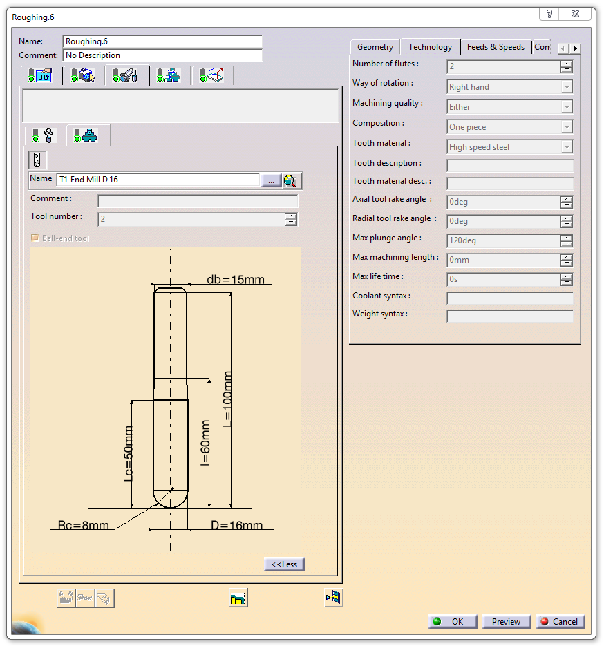
84

85

86 Finishing (6 pictures):
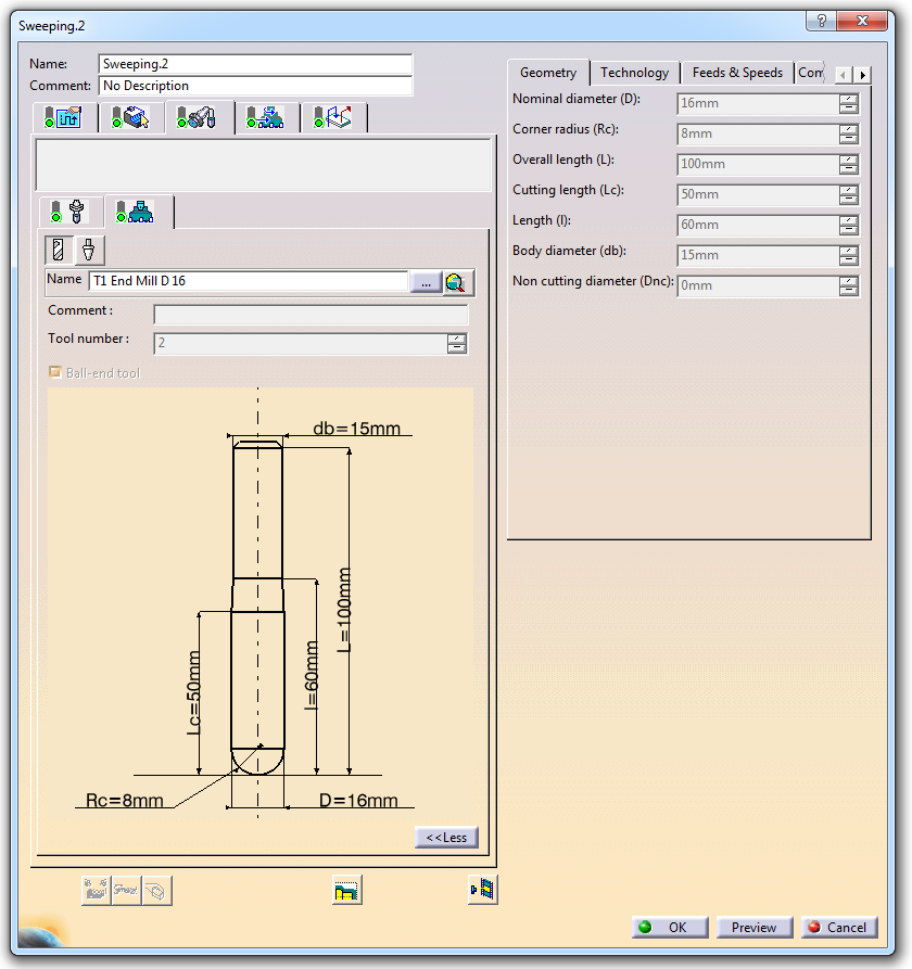
87

88
89 Appendix C: Material data MATERIALS Name Source Type Post-processing Flextural strength Flextural modulus Elong. at break Impact Izod notch Hardness Shore D Coeff of FDM SR-30 Stratasys Soluble Thermoplastic to 11 SR-100 Stratasys Soluble Thermoplastic to 105 ABS-M30 Stratasys Thermoplastic 0 53 MPa 2300MPa 4% 139 J/m Rockwell (>90ShoreD) Polycarbonate PC Stratasys Thermoplastic MPa 2200MPa 5% 53 J/m Rockwell R to 14 ULTEM 9085 Stratasys Thermoplastic MPa 2500MPa 6% 106 J/m to 17 PPSF Stratasys Thermoplastic MPa 2200MPa 3% 58.7 J/m Rockwell M86-60 to 20 Nylon 12 Stratasys Thermoplastic 0 69 MPa 1310MPa 30% 200 J/m - DuraForm FR 100 3D Systems 46 MPa 1462MPa 20% 49 J/m 73 DuraForm GF 3D Systems 37 MPa 3106 MPa 1.40% 41 J/m µm/ DuraForm HST Composite 3D Systems 83/64- x/y 4400/ x/y 4.5/2.7% 37.4 J/m 75 X-dir: 138 DuraForm PA 3D Systems 48 MPa 1287 MPa 14% 32 J/m µm/ Accura CastPro 3D Systems UV cure crosslinking 82 MPa 2310MPa % J/m μm Accura Xtreme 3D Systems UV cure crosslinking MPa MPa 14-22% J/m- Accura PEAK 3D Systems UV cure crosslinking heat postcure 120C MPa MPa % J/m μm/m Accura Bluestone 3D Systems UV cure crosslinking heat postcure 120C Mpa Mpa % J/m x1 Accura 55 3D Systems UV cure crosslinking MPa 3200MPa 5-8% j/m 85 61μm/m Zp150 Z corp Plaster infiltration, Z-max, epoxy 98 Mpa VisiJet PXL 3D Systems Plaster infiltration, ColorBond-cyanoacrylate/StrengthMax-epoxy 31.1/44.1 VisiJet M3 X 3D Systems UV cure crosslinking 0 65 MPa 8.30% RGD 525 Stratasys UV cure crosslinking % J/m 87 Digital ABS Stratasys UV cure crosslinking % J/m 85 PMMA Voxeljet AG Chem bonding infiltration epoxy SLS SL 3DP PolyJet Voxeljet
90 hss Shore D Coeff of thermal exp 0-50 C Coeff of thermal exp CHeat deflection at 0.4Mpa Heat deflection at 1.8Mpa Density Tg -60 to 110 C µm/(m C ) 82 C < max 345kPa autoclave 35 to 105 C µm/(m C ) 138 C < max 345kPa autoclave 121C recommended ll (>90ShoreD) 8.82E-05 mm/mm/ C 96 C ll R to 140 C µm/(m C ) 138 C to 170 C µm/(m C ) ll M86-60 to 200 C µm/(m C ) SLS C 70 C µm/m - C µm/m - C 179 C 134 C X-dir: µm/m- C Y-dir: X-dir: µm/m- C µm/m- C Y-dir: X-dir: µm/m- C 184 Y-dir: C X-dir: 179 C Y-dir: 135 C µm/m - C µm/m - C 180 C 95 C 1 SL μm/m- C μm/m- C μm/m - C 92 μm/m - C 78/153 as-is/postcured 59/124 as-is/postcured x10^-4 m/mc x10^-4 m/mc 65/ as-is/postcured μm/m - C 163μm/m - C DP 115C PolyJet Voxeljet softens at 80C
91 Appendix D: Comparison Calculation Data sheet for calculation: General Data Work hours per year 1765 hours % OECD average per year Economical lifespan 5 years Average wage manual labour sweden 2010 latest Hours per year 8760 Conversion rates Dollar to Euro 0.72 Valuta.se SEK to EUR SEK 0.11 Valuta.se Time utilization CNC 50.00% cliff 12H/dygn Printer 60.00% Stratasys 60.00% From Stratasys Setup Setup time CNC 1 hours Setup time Printer 0.25 hours Setup Cost CNC Setup Cost Printer 7.25 Machine Purchase Cost Amortization (per hour in lifespan) CNC 2,200, Corea Rapid 40 (Cliff 20 million SEK) Small CNC 550, Famu Aktive Five 2000 (Cliff 5 million SEK) Makerbot Replicator 2 1, Stratasys Fortus 400mc XX 3.79 From Stratasys 5.27$ Stratasys Fortus 900mc XX From Stratasys 14.05$ Stratasys Fortus 900mc 288, For comparison Material Costs Source Stratasys Euro/inch^3 EUR/m^3 ABS-M30 $ ,567 PC $ ,484 PC-ABS $ ,484 PPSF $ ,559 Ultem 9085 $ ,559 SR20 $ ,032 SR30 $ ,389 SR100 $ ,346 S1 $ ,559 PC-BASS $ ,484 PPSF-BASS $ ,559 AM Sparse structure density 15.00% Stratasys double dense infill PUR material cost RAMPF Tooling PC granules PC filament 3000 Alibaba Alibaba
 0.10632 0.22500 0.933 8.")
92 Calculation table: Tool Mould volume Block Volume Mould Surface CNC Ratio Surface/ mould Processing volume Setup CNC Setup AM time Runner Bot Runners Top Plenum Bottom Plenum Top Blade (test 1) Bottle (test 2) Shovel (test 3) Curvature Nosecone Rear wing bot
Additive Manufacturing: Processes and Standard Terminology
 Additive Manufacturing: Processes and Standard Terminology Gary Coykendall Copyright Edmonds Community College 2012; Permission granted for use and reproduction for educational purposes only. Abstract
RAPID PROTOTYPING. Learning Objectives: By the end of the lecture the student should be able to: Explain the fundamentals of Rapid Prototyping
 RAPID PROTOTYPING Learning Objectives: By the end of the lecture the student should be able to: Explain the fundamentals of Rapid Prototyping Outline and explain differences of Rapid Prototyping Technologies
GLOBAL MANUFACTURING. ARAUJO, Anna Carla AUG, 2015 Mechanical Engineering Department POLI/COPPE/UFRJ
 GLOBAL MANUFACTURING ARAUJO, Anna Carla AUG, 2015 Mechanical Engineering Department POLI/COPPE/UFRJ Workpiece Presentation Powder Metallurgy and Additive Manufacturing [#7] Powder Metallurgy PM parts can
Chapter 5 POWDER-BASED RAPID PROTOTYPING SYSTEMS
 Chapter 5 POWDER-BASED RAPID PROTOTYPING SYSTEMS 5.1 3D SYSTEMS SELECTIVE LASER SINTERING (SLS) 5.1.1 Company 3D Systems Corporation was founded by Charles W. Hull and Raymond S. Freed in 1986. The founding
As published in PIM International
 As published in PIM International www.pim-international.com 64 Powder Injection Moulding International September 2012 Rapid prototyping of highperformance ceramics opens new opportunities for the CIM industry
Rapid Prototyping. Training Objective
 Training Objective After watching the program and reviewing this printed material, the viewer will understand the principles and practical applications of Rapid Prototyping. Basic concepts are explained
Tutorial: Rapid Prototyping Technologies
 1. Introduction Tutorial: Rapid Prototyping Technologies Rapid prototyping (RP) is a new manufacturing technique that allows for fast fabrication of computer models designed with three-dimension (3D) computer
How To Build A 3D Model From Scratch
 SERVICES AND CAPABILITIES 1. Rapid prototyping What is rapid prototyping? Rapid prototyping (RP) or more recently Free Form Fabrication refers to the fabrication of a physical, three-dimensional part of
Ningbo Yinzhou Keao Prototyping & Mould Factory Services include : CNC machining prototypes,
 Ningbo Yinzhou Keao Prototyping & Mould Factory Services include : CNC machining prototypes, STEREOLITHOGRAPHY (SLA) Selective Laser Sintering (SLS) RTV MOLDING AND CAST URETHANE PROTOTYPES Tel : +86 574
Brief Report on machines available in the 3D Printers market and their characteristics
 Brief Report on machines available in the 3D Printers market and their characteristics by AJIU Asociaciòn de investigacion de la industria del juguete, conexas y afines, Contenido 1. 3D PRINTING... 3 2.
ID@GT prepared by Gabe Landes for T. Purdy 2009
 Rapid prototyping is the automatic construction of physical objects using solid freeform fabrication. The first techniques for rapid prototyping became available in the late 1980s and were used to produce
Andreas Gebhardt. Rapid Prototyping HANSER. Hanser Publishers, Munich Hanser Gardner Publications, Inc., Cincinnati
 Andreas Gebhardt Rapid Prototyping HANSER Hanser Publishers, Munich Hanser Gardner Publications, Inc., Cincinnati Contents 1 Product Development - Product Formation - Rapid Product Development 1 1.1 New
COURSE: ADVANCED MANUFACTURING PROCESSES. Module No. 5: OTHER PROCESSES
 COURSE: ADVANCED MANUFACTURING PROCESSES Module No. 5: OTHER PROCESSES Lecture No-2 Rapid Prototyping Technology (RPT) Background: In this age of fast growth (rapid technology age), customer demands are
How to Effectively Move from 3D Printing to Injection Molding. Tony Holtz Technical Specialist, Proto Labs
 How to Effectively Move from 3D Printing to Injection Molding Tony Holtz Technical Specialist, Proto Labs Overview 3D Printing CNC Machining Injection Molding Design Considerations for Injection Molding
Rapid prototyping. CAD / lecture. October 5, 2010. TO&I Vermelding onderdeel organisatie
 1 Rapid prototyping is: Rapid prototyping is an additive (layered) digital fabrication technology Layers of material are added forming the final 3d physical model The digital data of the virtual 3d model
ROHACELL Triple F. Complex shaped PMI Foam Cores for highly efficient FRP Composite
 Complex shaped PMI Foam Cores for highly efficient FRP Composite ROHACELL Triple F Sandwich Fabrication for low to - A Novel Particle Foam high volume applications SAMPE tesdr. Kay Brazil Conference 2015
1. Injection Molding (Thermoplastics)
") 1. Injection Molding (Thermoplastics) l Molding: Injection (thermoplastics) INJECTION MOLDING of thermoplastics is the equivalent of pressure die casting of metals. Molten polymer is injected under high
1. Injection Molding (Thermoplastics) l Molding: Injection (thermoplastics) INJECTION MOLDING of thermoplastics is the equivalent of pressure die casting of metals. Molten polymer is injected under high
TUTOR NOTES. How to use this pack. Rapid prototyping in schools. Definition
 TUTOR NOTES How to use this pack This pack is aimed at students studying for both Intermediate 2 and Higher Product Design. Students of other subjects might find it useful, and a Curriculum Map has been
Good Boards = Results
 Section 2: Printed Circuit Board Fabrication & Solderability Good Boards = Results Board fabrication is one aspect of the electronics production industry that SMT assembly engineers often know little about.
Advanced Manufacturing Choices
 Advanced Manufacturing Choices MAE 195-MAE 156 Spring 2009, Dr. Marc Madou Class 8: Rapid Prototyping By Dr. Miodrag Micic, mmicic@mpbio.com Two Ways for Fabrication: Substractive manufacturing Additive
Glossary. 3D Animation Using computer software to create and animate a three-dimensional representation of image data.
 Glossary # 2D Control Drawing A line drawing showing various views of a product with details such as material, surface finish, volume, tolerances and critical dimensions. 3D Animation Using computer software
DESIGN OF MANUFACTURING SYSTEMS BY RAPID PROTOTYPING TECHNOLOGY APPLICATION
 Annals of the University of Petroşani, Mechanical Engineering, 14 (2012), 104-111 104 DESIGN OF MANUFACTURING SYSTEMS BY RAPID PROTOTYPING TECHNOLOGY APPLICATION JOZEF NOVAK-MARCINCIN 1 Abstract: Rapid
PROCESSING OF VARIOUS MATERIALS
 4 PROCESSING OF VARIOUS MATERIALS CHAPTER CONTENTS 4.1 Shaping Processes for Polymers Polymers Manufacturing Processes for Polymers 4.2 Rubber Processing Technology Processing of rubber into finished good
BENEFITS OF 3D PRINTING VACUUM FORM MOLDS
 WHITE PAPER BENEFITS OF 3D PRINTING VACUUM FORM MOLDS AUTHORS COLE HARTMAN (MECHANICAL ENGINEER) & VERONICA DE LA ROSA (INDUSTRIAL DESIGNER) FATHOM is driven by advanced technologies. We leverage our expertise
Rapid Prototyping Technologies. May, 2016
 Rapid Prototyping Technologies May, 2016 WE HAVE ALL THE NECESSARY TOOLS TO ENSURE THE FINAL SUCCESS OF YOUR PROTOTYPE. Andaltec can help you in all the steps, from the design to fully finished prototype
Choosing optimal rapid manufacturing process for thin-walled products using expert algorithm
 Choosing optimal rapid manufacturing process for thin-walled products using expert algorithm Filip Górski, Wiesław Kuczko, Radosław Wichniarek, Adam Dudziak, Maciej Kowalski, Przemysław Zawadzki Poznan
Prototyping Process Choosing the best process for your project
 Prototyping Process Choosing the best process for your project Proto Labs, Inc. 5540 Pioneer Creek Dr. Maple Plain, MN 55359 P: (763) 479 3680 F: (763) 479 2679 www.protolabs.com 2009 Proto Labs. All rights
Thermoplastic composites
 Thermoplastic composites Definition By definition, a thermoplastic is a material based on polymer (macromolecular compound) which can be shaped, in a liquid (viscous) state at a temperature either higher
Solid shape molding is not desired in injection molding due to following reasons.
 PLASTICS PART DESIGN and MOULDABILITY Injection molding is popular manufacturing method because of its high-speed production capability. Performance of plastics part is limited by its properties which
The Prototyping Challenges with Micro Molding: A Comparative Study of Prototyping Methods for Micro Molding Applications
 I. The Premise A lot has changed in the last 20+ years. Just two short decades ago our top speed personal computer processors were clocked at 386 MHz, hard drive space and RAM memory were still measured
Tool Design and Concurrent Engineering using Rapid Tooling Construction Methods
 Section Number 3563 Tool Design and Concurrent Engineering using Rapid Tooling Construction Methods Nicole Hoekstra Engineering Technology Department Western Washington University Abstract Prior to rapid
Theoretical and Experimental Contributions Regarding the Optimization of Rapid Prototyping Technologies
 TECHNICAL UNIVERSITY OF CLUJ-NAPOCA FACULTY OF MACHINE BUILDING Theoretical and Experimental Contributions Regarding the Optimization of Rapid Prototyping Technologies Doctoral thesis ABSTRACT Scientific
FLEXIBLE CIRCUITS MANUFACTURING
 IPC-DVD-37 FLEXIBLE CIRCUITS MANUFACTURING Below is a copy of the narration for DVD-37. The contents of this script were developed by a review group of industry experts and were based on the best available
Sample Pages. Andreas Gebhardt. Understanding Additive Manufacturing. Rapid Prototyping - Rapid Tooling - Rapid Manufacturing
 Sample Pages Andreas Gebhardt Understanding Additive Manufacturing Rapid Prototyping - Rapid Tooling - Rapid Manufacturing ISBN (Buch): 978-3-446-42552-1 ISBN (E-Book): 978-3-446-43162-1 For further information
Tech Transfer to Start-up and Manufacturing - Fabrication. Chris Moody
 Tech Transfer to Start-up and Manufacturing - Fabrication Chris Moody Fabrication Incubators Business incubators can be just office space with business services and advice or they can provide early manufacturing
RAPID PROTOTYPING TECHNOLOGIES, APPLICATIONS AND PART DEPOSITION PLANNING
 RAPID PROTOTYPING TECHNOLOGIES, APPLICATIONS AND PART DEPOSITION PLANNING Pulak M. Pandey Department of Mechanical Engineering Indian Institute of Technology Delhi Email: pmpandey@mech.iitd.ac.in 1. INTRODUCTION
How to reduce the cure time without damaging the rubber compound during injection molding?
 How to reduce the cure time without damaging the rubber compound during injection molding? 0Introduction This article aims at analyzing the rubber injection process and highlighting the limits that prevent
Production of Wind Tunnel Testing Models with use of Rapid Prototyping Methods
 Production of Wind Tunnel Testing Models with use of Rapid Prototyping Methods R. ADELNIA 1, S. DANESHMAND 2, S. AGHANAJAFI 3 Mechanical Group, Majlesi Azad University Isfahan IRAN Abstract: In a time
Determining the Right Molding Process for Part Design
 Determining the Right Molding Process for Part Design How RIM Molding Advantages Compare with Traditional Production Technologies Page 2 Introduction This White Paper details the part production processes
Fused Deposition Modeling: A Technology Evaluation
 Fused Deposition Modeling: A Technology Evaluation Todd Grimm T. A. Grimm & Associates, Inc. Selecting the best rapid prototyping process can be challenging. Without hands-on experience, uncovering both
Allison Rae Paramount Industries Rhode Island School of Design ID 87. Prototyping Overview
 Allison Rae Paramount Industries Rhode Island School of Design ID 87 Prototyping Overview Prototyping for Mechanical Parts Paramount Industries Started as prototyping vendor, then added: Industrial Design
PRELIMINARY COMPONENT INTEGRATION USING RAPID PROTOTYPING TECHNIQUES
 J! PRELIMINARY COMPONENT INTEGRATION USING RAPID PROTOTYPING TECHNIQUES by Ken Cooper National Aeronautics and Space Administration Building 4707, Marshall Space Flight Center George C. Marshall Space
Basic Properties and Application of Auto Enamels
 Basic Properties and Application of Auto Enamels Composition of Ceramic Automotive Glass Enamels Ceramic automotive glass colours are glass enamels that fire on to the glass during the bending process
Construction. 3-part thixotropic epoxy patching mortar. Product Description. Tests
 Product Data Sheet Edition 05/12/2014 Identification no: 020204030010000044 Sikadur -41 CF Rapid 3-part thixotropic epoxy patching mortar Construction Product Description Uses Characteristics / Advantages
Selective Laser Sintering of Duraform TM Polyamide with Small-Scale Features
 Selective Laser Sintering of Duraform TM Polyamide with Small-Scale Features Vinay Sriram, Kristin Wood, David Bourell and Joseph J Beaman Department of Mechanical Engineering Laboratory of Freeform Fabrication
PRECISION PROTOTYPING THE ROLE OF 3D PRINTED MOLDS IN THE INJECTION MOLDING INDUSTRY
 By Lior Zonder, Applications Team Leader Nadav Sella, Solutions Sales Manager, Global Field Operations Injection molding (IM) the process of injecting plastic material into a mold cavity where it cools
Casting. Training Objective
 Training Objective After watching the program and reviewing this printed material, the viewer will learn the essentials of the various metal casting processes used in industry today. The basic principles
New Advances in Rapid Prototyping using Inkjet-based 3D Printing
 New Advances in Rapid Prototyping using Inkjet-based 3D Printing April 2011 Objet Geometries Ltd. DISCLAIMER: Objet Geometries Ltd. ("Objet") does not guarantee the final release and availability of materials,
Injection molding equipment
 Injection Molding Process Injection molding equipment Classification of injection molding machines 1. The injection molding machine processing ability style clamping force(kn) theoretical injection volume(cm3)
CHAPTER 2 INJECTION MOULDING PROCESS
 CHAPTER 2 INJECTION MOULDING PROCESS Injection moulding is the most widely used polymeric fabrication process. It evolved from metal die casting, however, unlike molten metals, polymer melts have a high
MILMAN & ASSOCIATES STRUCTURAL CONSULTING ENGINEERS/ PROJECT MANAGERS
 MILMAN & ASSOCIATES STRUCTURAL CONSULTING ENGINEERS/ PROJECT MANAGERS May 29, 2013 Revision B Structural Guideline for Design and Installation Holes in Composite Floor Slab Terminal 3, Departure Level
PRODUCT INFORMATION : ADHESIVES DELIVERING THE FUTURE OF COMPOSITE SOLUTIONS ADHESIVES. contact@gurit.com www.gurit.com
 PRODUCT INFORMATION : ADHESIVES DELIVERING THE FUTURE OF COMPOSITE SOLUTIONS ADHESIVES contact@gurit.com Gurit is a technical leader in the formulation of advanced epoxy resins, and offers a range of two
Welding of Plastics. Amit Mukund Joshi. (B.E Mechanical, A.M.I.Prod.E)
") Welding of Plastics Amit Mukund Joshi (B.E Mechanical, A.M.I.Prod.E) Introduction Mechanical fasteners, adhesives, and welding processes can all be employed to form joints between engineering plastics.
Welding of Plastics Amit Mukund Joshi (B.E Mechanical, A.M.I.Prod.E) Introduction Mechanical fasteners, adhesives, and welding processes can all be employed to form joints between engineering plastics.
NASA FACULTY FELLOWSHIP PROGRAM MARSHALL SPACE FLIGHT CENTER THE UNIVERSITY OF ALABAMA
 2002 NASA FACULTY FELLOWSHIP PROGRAM MARSHALL SPACE FLIGHT CENTER THE UNIVERSITY OF ALABAMA Development of Processing Parameters for Organic Binders Using Selective Laser Sintering Prepared By: Academic
DIESEL EFFECT PROBLEM SOLVING DURING INJECTION MOULDING
 RESEARCH PAPERS FACULTY OF MATERIALS SCIENCE AND TECHNOLOGY IN TRNAVA SLOVAK UNIVERSITY OF TECHNOLOGY IN BRATISLAVA 2014 Volume 22, Special Number DIESEL EFFECT PROBLEM SOLVING DURING INJECTION MOULDING
INJECTION MOLDING COOLING TIME REDUCTION AND THERMAL STRESS ANALYSIS
 INJECTION MOLDING COOLING TIME REDUCTION AND THERMAL STRESS ANALYSIS Tom Kimerling University of Massachusetts, Amherst MIE 605 Finite Element Analysis Spring 2002 ABSTRACT A FEA transient thermal structural
3D Printing Design Guidelines Sierra College CACT
 3D Printing Design Guidelines Sierra College CACT Prepared by ARW Consulting June 30, 2009 Table of Contents Scope of this Document.. 1 General Overview... 2 File Format.. 3 SST Support Material.. 4 Venting
Product Data. HexPly 8552 Epoxy matrix (180 C/356 F curing matrix)
") HexPly 8552 Epoxy matrix (180 C/356 F curing matrix) Product Data Description HexPly 8552 is a high performance tough epoxy matrix for use in primary aerospace structures. It exhibits good impact resistance
HexPly 8552 Epoxy matrix (180 C/356 F curing matrix) Product Data Description HexPly 8552 is a high performance tough epoxy matrix for use in primary aerospace structures. It exhibits good impact resistance
CHARACTERIZATION OF POLYMERS BY TMA. W.J. Sichina, National Marketing Manager
 PERKIN ELMER Polymers technical note CHARACTERIZATION OF POLYMERS BY W.J. Sichina, National Marketing Manager Thermomechanical analysis () is one of the important characterization techniques in the field
A Study on Investment Casting Directly with Plastic Rapid Prototype Patterns
 November 2010, Volume 4, No.11 (Serial No.36) Journal of Materials Science and Engineering, ISSN 1934-8959, USA A Study on Investment Casting Directly with Plastic Rapid Prototype Patterns Songhao Wang
How to Build a Printed Circuit Board. Advanced Circuits Inc 2004
 How to Build a Printed Circuit Board 1 This presentation is a work in progress. As methods and processes change it will be updated accordingly. It is intended only as an introduction to the production
REPAIR MANUAL MATERIALS
 MATERIALS Balsa: Raw material for FST (Future Shape Technology series) rails or parabolic stringers. It is what gives our unique product its excellent performance characteristics. Quality repair of this
3D Printed Injection Molding Tool ("PIMT") Guide. Objet Ltd.
 Guide. Objet Ltd.") 3D Printed Injection Molding Tool ("PIMT") Guide Objet Ltd. 2 Injection molding is a high speed, automated and versatile process that can produce high precision complex three dimensional parts from a fraction
3D Printed Injection Molding Tool ("PIMT") Guide Objet Ltd. 2 Injection molding is a high speed, automated and versatile process that can produce high precision complex three dimensional parts from a fraction
Somos Materials. Injection Molding Using Rapid Tooling
 Somos Materials Injection Molding Using Rapid Tooling Introduction Testing a new design before costly tooling is created can save companies time and money. For many years, the only process available to
COMPOSITE MATERIALS. Asst. Prof. Dr. Ayşe KALEMTAŞ
 COMPOSITE MATERIALS Office Hours: Tuesday, 16:30-17:30 akalemtas@mu.edu.tr, akalemtas@gmail.com Phone: +90 252 211 19 17 Metallurgical and Materials Engineering Department ISSUES TO ADDRESS Classification
Fundamentals of Design for Plastic Injection Molding. Kelly Bramble
 Fundamentals of Design for Plastic Injection Molding Kelly Bramble 1 Fundamentals of Design for Plastic Injection Molding Copyright, Engineers Edge, LLC www.engineersedge.com All rights reserved. No part
4 Thermomechanical Analysis (TMA)
") 172 4 Thermomechanical Analysis 4 Thermomechanical Analysis (TMA) 4.1 Principles of TMA 4.1.1 Introduction A dilatometer is used to determine the linear thermal expansion of a solid as a function of temperature.
172 4 Thermomechanical Analysis 4 Thermomechanical Analysis (TMA) 4.1 Principles of TMA 4.1.1 Introduction A dilatometer is used to determine the linear thermal expansion of a solid as a function of temperature.
REPAIR CONCEPT SUPPORTED BY LASER REMOVAL AND INDUCTIVE HEATING
 28 TH INTERNATIONAL CONGRESS OF THE AERONAUTICAL SCIENCES REPAIR CONCEPT SUPPORTED BY LASER REMOVAL AND INDUCTIVE HEATING Markus Kaden*, Rüdiger Keck* *German Aerospace Center markus.kaden@dlr.de;ruediger.keck@dlr.de
Comparative Cost Study of a 35m Wind Turbine Blade using Infusion and Prepreg Materials Technology
 Comparative Cost Study of a 35m Wind Turbine Blade using Infusion and Prepreg Materials Technology Introduction Wind turbine blades are manufactured using advanced composite materials due to their specific
SCOUT EPOXY-INFUSES NEW 42-FOOT SPORT FISHING BOAT
 SCOUT EPOXY-INFUSES NEW 42-FOOT SPORT FISHING BOAT New Process Reduces Weight, Increases Hydrodynamic Performance, Improves Dark Hull Cosmetic Surface Scout Boats, Inc. (Summerville, SC) introduced its
DETERMINATION OF TIME-TEMPERATURE SHIFT FACTOR FOR LONG-TERM LIFE PREDICTION OF POLYMER COMPOSITES
 DETERMINATION OF TIME-TEMPERATURE SHIFT FACTOR FOR LONG-TERM LIFE PREDICTION OF POLYMER COMPOSITES K. Fukushima*, H. Cai**, M. Nakada*** and Y. Miyano*** * Graduate School, Kanazawa Institute of Technology
Integrative Optimization of injection-molded plastic parts. Multidisciplinary Shape Optimization including process induced properties
 Integrative Optimization of injection-molded plastic parts Multidisciplinary Shape Optimization including process induced properties Summary: Andreas Wüst, Torsten Hensel, Dirk Jansen BASF SE E-KTE/ES
Outline of a quality system and standard for the certification of conformity
 Outline of a quality system and standard for the certification of conformity Although still in early steps, novel Additive Manufacturing (AM) processes are growing in expectations as enabling technology
8 EXTRA LIGHT GRC SANDWICH ELEMENTS FOR ROOFING IN INDUSTRIAL BUILDINGS
 8 EXTRA LIGHT GRC SANDWICH ELEMENTS FOR ROOFING IN INDUSTRIAL BUILDINGS MARICA DELLA BELLA and DIEGO CIAN Precompressi Centro Nord S.p.A., Italy SUMMARY: Secondary roofing elements, complementary to the
3M Scotch-Weld EPX Two-component structural adhesives and applicator guns
 M Scotch-Weld EPX Two-component structural adhesives and applicator guns Innovation What is a structural adhesive? M s high-strength structural adhesives are fundamentally load-bearing formulations. Bond
Effects of Tg and CTE on Semiconductor Encapsulants
 Effects of Tg and CTE on Semiconductor Encapsulants Dr. Mark M. Konarski Loctite Corporation www.loctite.com Abstract As the role of direct-chip-attachment increases in the electronics industry, the reliability
MANUFACTURING THE FUTURE
 Paul Miller 803-554-3590 paul.miller@3dsystems.com MANUFACTURING THE FUTURE PAUL MILLER DIRECTOR OF SALES WWW.3DSYSTEMS.COM NYSE:DDD 2013 3DSYSTEMS A 3D PRINTER FOR YOU RESULTING IN UNMATCHED 3D PRINTER
Xantu.LayrTM nanofibre interleaving veils provide a technological leap forward for the toughening of high performance composites.
 Continuous Nanofibre. Performance composites Xantu.LayrTM nanofibre interleaving veils provide a technological leap forward for the toughening of high performance composites. Xantu.LayrTM enhances composite
Scotch-Weld TM. DP410 Off-White. Product Data Sheet. Product Description. Key Features Rapid cure at room temperature; cure rate may be accelerated
 Scotch-Weld TM Product Data Sheet DP410 Off-White Supersedes: October 2001 Product Description DP410 epoxy adhesive is a low flow, two-part epoxy based structural adhesive. It is designed for use where
THE COMPOSITE DISC - A NEW JOINT FOR HIGH POWER DRIVESHAFTS
 THE COMPOSITE DISC - A NEW JOINT FOR HIGH POWER DRIVESHAFTS Dr Andrew Pollard Principal Engineer GKN Technology UK INTRODUCTION There is a wide choice of flexible couplings for power transmission applications,
CHAPTER 5. OVERVIEW OF THE MANUFACTURING PROCESS
 CHAPTER 5. OVERVIEW OF THE MANUFACTURING PROCESS 5.1 INTRODUCTION The manufacturing plant considered for analysis, manufactures Printed Circuit Boards (PCB), also called Printed Wiring Boards (PWB), using
Getting rid of the wires: Curved Layer Fused Deposition Modeling in Conductive Polymer Additive Manufacturing
 Getting rid of the wires: Curved Layer Fused Deposition Modeling in Conductive Polymer Additive Manufacturing DIEGEL, Olaf 1, a, SINGAMNENI, Sarat 1, b, HUANG, Ben 1, c, GIBSON, Ian 2, d 1 Centre for Rapid
Facts About. Industrial gases for better injection molding. This article appeared in the trade journal Kunststoffe plast europe, issue 12/2004.
 Facts About. Industrial gases for better injection molding. This article appeared in the trade journal Kunststoffe plast europe, issue 12/2004. 2 Industrial gases for better injection molding Gas injection
CHARACTERIZATION OF HIGH PRESSURE RTM PROCESSES FOR MANUFACTURING OF HIGH PERFORMANCE COMPOSITES
 CHARACTERIZATION OF HIGH PRESSURE RTM PROCESSES FOR MANUFACTURING OF HIGH PERFORMANCE COMPOSITES R. Chaudhari 1*, M. Karcher 1, P. Elsner 1, F. Henning 1 1 Fraunhofer Institute for Chemical Technology,
Additional requirements and conditions for abrasive products to be marked with the osa symbol
 Appendix of paragraph 3 of the Conditions of Use for the osa Trademark Additional requirements and conditions for abrasive products to be marked with the osa symbol Conformance with the European safety
WATERPROOFING OF REINFORCED CONCRETE FLAT ROOF 12
 WATERPROOFING OF REINFORCED CONCRETE FLAT ROOF 12 87 88 GOOD INDUSTRY PRACTICES 12 WATERPROOFING OF REINFORCED CONCRETE FLAT ROOF 12.1 BACKGROUND Most roofs in Singapore are constructed using reinforced
Auditing a Printed Circuit Board Fabrication Facility Greg Caswell
 Auditing a Printed Circuit Board Fabrication Facility Greg Caswell Introduction DfR is often requested to audit the PCB fabrication process of a customer s supplier. Understanding the process variations
SAMPLE TEST QUESTIONS MOTOR VEHICLE BODY REPAIRER- ITA WEBSITE
 1 How are spot welds located on the underside of an apron? A. Heat the undercoat with a torch. B. Visually inspects with a trouble light. C. Grind the surface with an angle grinder. D. Clean factory seams
NetShape - MIM. Metal Injection Molding Design Guide. NetShape Technologies - MIM Phone: 440-248-5456 31005 Solon Road FAX: 440-248-5807
 Metal Injection Molding Design Guide NetShape Technologies - MIM Phone: 440-248-5456 31005 Solon Road FAX: 440-248-5807 Solon, OH 44139 solutions@netshapetech.com 1 Frequently Asked Questions Page What
3D Printing, Additive Manufacturing, and Solid Freeform Fabrication: The Technologies of the Past, Present
 and Future Joseph J Beaman NSF Additive Manufacturing Workshop 3D Printing, Additive Manufacturing, and Solid Freeform Fabrication: The Technologies of the Past, Present The University of Texas Solid
HIGH PERFORMANCE PRE-APPLIED SYSTEM FOR BLIND SIDE & BELOW GRADE WATERPROOFING APPLICATIONS
 BSW HIGH PERFORMANCE PRE-APPLIED SYSTEM FOR BLIND SIDE & BELOW GRADE WATERPROOFING APPLICATIONS BSW is a fully reinforced Pre-Applied system membrane designed for horizontal and vertical external blind-side
Free piston Stirling engine for rural development
 Free piston Stirling engine for rural development R. Krasensky, Intern, Stirling development, r.krasensky@rrenergy.nl W. Rijssenbeek, Managing director, w.rijssenbeek@rrenergy.nl Abstract: This paper presents
e-manufacturing Solutions
 Laser-sintering produces directly from 3D CAD data fast, flexibly and cost-effectively. Process and Benefits Process Laser-sintering is a generative layer manufacturing technology. Any three-dimensional
Understanding Plastics Engineering Calculations
 Natti S. Rao Nick R. Schott Understanding Plastics Engineering Calculations Hands-on Examples and Case Studies Sample Pages from Chapters 4 and 6 ISBNs 978--56990-509-8-56990-509-6 HANSER Hanser Publishers,
the runnerless types of molds are explained post molding operations are described the basic methods of applied decoration methods are examined
 Training Objectives After watching the video and reviewing this printed material, the viewer will gain knowledge and understanding of the various plastic finishing processes used in industry and their
GRADATION OF AGGREGATE FOR CONCRETE BLOCK
 GRADATION OF AGGREGATE FOR CONCRETE BLOCK Although numerous papers have been written concerning the proper gradation for concrete mixes, they have generally dealt with plastic mixes, and very little published
3D PRINTING OF CONTINUOUS FIBER REINFORCED PLASTIC
 3D PRINTING OF CONTINUOUS FIBER REINFORCED PLASTIC Masaki NAMIKI 1, Masahito UEDA 1, Akira TODOROKI 2 Yoshiyasu HIRANO 3, Ryosuke MATSUZAKI 4 1 Nihon University, 1-8-14 Kanda-surugadai, Chiyoda, Tokyo,
Ceralink Capabilities and Opportunities
 Ceralink Capabilities and Opportunities Dr. Holly Shulman President, Materials Scientist Ceralink Inc. Rensselaer Technology Park 105 Jordan Rd. Troy, New York 12180 holly@ceralink.com www.ceralink.com
The Fundamental Principles of Composite Material Stiffness Predictions. David Richardson
 The Fundamental Principles of Composite Material Stiffness Predictions David Richardson Contents Description of example material for analysis Prediction of Stiffness using Rule of Mixtures (ROM) ROM with