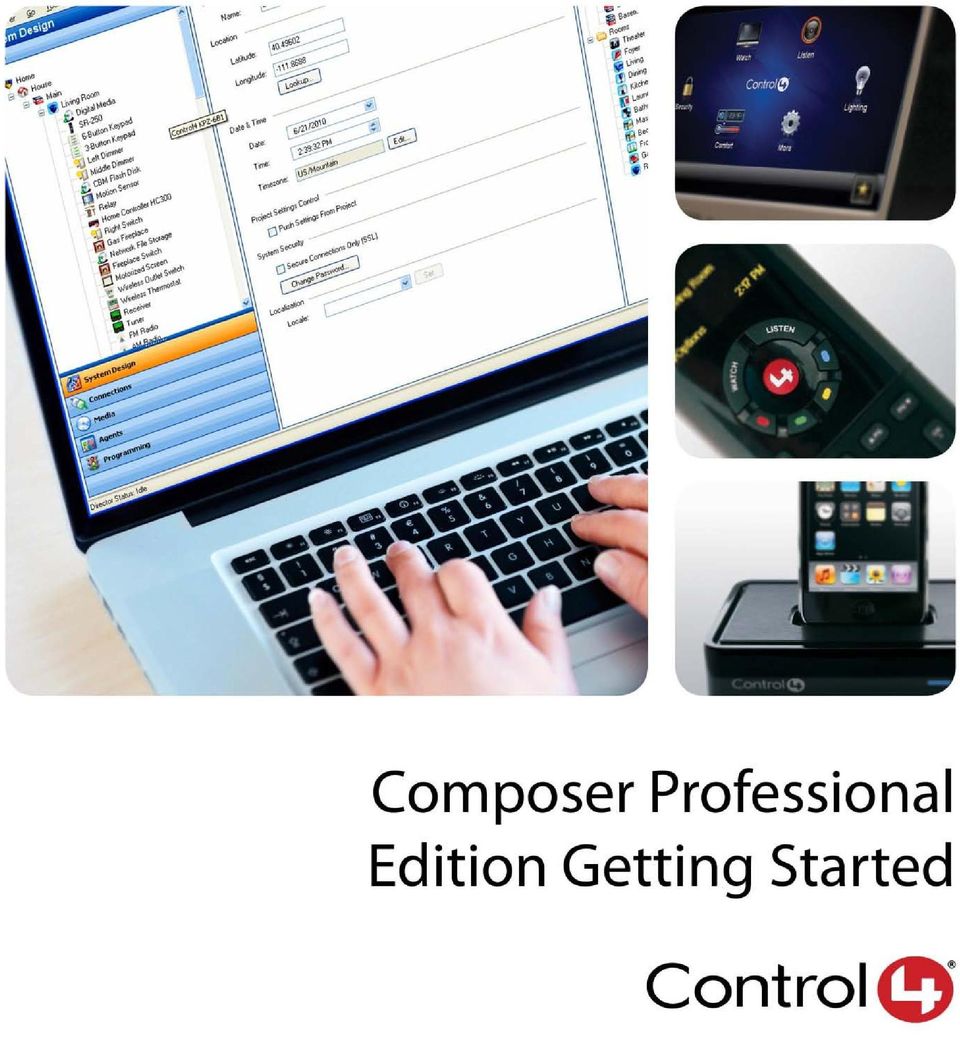
Composer Pro Getting Started
|
|
|
- Cecilia Stafford
- 7 years ago
- Views:
Transcription
1
2 Composer Pro Control4 Disclaimer Control4 makes no representations or warranties with respect to this publication, and specifically disclaims any express or implied warranties of merchantability or fitness for any particular purpose. Control4 reserves the right to make changes to any and all parts of this publication at any time, without any obligation to notify any person or entity of such changes. Trademarks Control4 and the Control4 logo are registered trademarks of Control4 Corporation. Other product and company names mentioned in this document may be the trademarks or registered trademarks of their respective owners. Legal Notice GNU GNU GENERAL PUBLIC LICENSE TERMS AND CONDITIONS FOR COPYING, DISTRIBUTION AND MODIFICATION (Section 3.b.) You may copy and distribute the Program (or a work based on it, under Section 2) in object code or executable form under the terms of Sections 1 and 2 above provided that you also do one of the following: Accompany it with a written offer, valid for at least three years, to give any third party, for a charge no more than your cost of physically performing source distribution, a complete machine-readable copy of the corresponding source code, to be distributed under the terms of Sections 1 and 2 on a medium customarily used for software interchange. The complete text for this license is available on the Control4 web site at: Gracenote Gracenote, Gracenote logo and logotype, and the "Powered by Gracenote" logo are either a registered trademark or a trademark of Gracenote, Inc. in the United States and/or other countries. Music and DVD recognition technology and related data are provided by Gracenote. Gracenote is the industry standard in Music and DVD recognition technology and related content delivery. For more information visit MPEG Fraunhofer IIS and Thomson. MPEG Layer-3 audio coding technology licensed from Fraunhofer IIS and Thomson. Supply of this product does not convey a license nor imply any right to distribute content created with this product in revenue-generating broadcast systems (terrestrial, satellite, cable, and /or other distribution channels), streaming applications (via Internet, intranets, and/or other networks), other content distribution systems (pay-audio or audio-on-demand applications, and the like) or on physical media (compact discs, digital versatile discs, semiconductor chips, hard drives, memory cards, and the like). An independent license for such use is required. For details, visit Radio Locator is the service provider of AM/FM channel list All Media Guide, LLC provides music and video recognition technology that provides cover art and related text that enriches the Control4 user Navigators. Copyright 2010 Control4. All rights reserved. Control4, Control4 logo and Everyday Easy are registered trademarks or trademarks of Control4 Corporation in the United States and/or other countries. All other brands or names may be claimed as property by their respective owners. Pricing and specifications subject to change without notice. No part of this publication may be reproduced, photocopied, stored on a retrieval system, or transmitted without the express written consent of the publisher. Contact Information Control4 Corporation S. Election Road Salt Lake City, UT USA Part number: Composer Professional Edition (OS 2.0) Page 2 of 132

3 Composer Pro Contents 1. Introduction Purpose Related Documents and Resources Composer Pro Overview Setting Up the Control4 System Overview Composer Pro System Requirements Installing the Hardware and Software Installing and Connecting the Hardware Installing Composer Pro Software Procedure Exploring Composer Pro Features Composer Pro Startup Options Start Composer Exit Composer Composer Pro Views Available Views Connecting to a Director Connecting to a Virtual Director Saving Changes When Working Virtually Using Virtual Mode Connecting to a Director on a Local Network Procedure Setting Up Remote Access Prerequisites Procedures Connecting to a Director Using Remote Access Requirements Configuring Remote Access Connecting Using Remote Access Ensuring that Director and Composer Are Compatible Designing the Control4 System Prerequisites Page 3 of 132

4 Composer Pro 6.2 Introduction to Designing a Control4 System Purpose of Device Drivers Adding Items to the Project Tree Building a Project in System Design Composer Pro Design Methods Making and Testing the Connections Connecting the Hardware Testing the Device Connections Testing Network Connections Testing Control and AV Connections Testing Room Connections Registering the Control4 System Register the System at my.control4.com Register the Controller from Composer Register the System Through a Touch Screen or On-Screen Navigator Setting Up a 4Sight Subscription Prerequisites Procedure Purchasing and Setting Up Dealer Licenses Prerequisites What s New in Release 2.0? Hardware, Software, and Media Support New or Updated Sections Hardware and Software No Longer Supported or Partially Supported Hardware that Doesn t Support ZigBee Pro Where to Go from Here Contacting Control4 Technical Support Project Build Examples Using System Design Examples Using System Design Example: Using System Design to Add Devices to a Theater Room Procedure Example: Using System Design to Add a Receiver to the Theater Room Procedure Example: Using System Design to Add a TV to the Theater Room Procedure Page 4 of 132

5 Composer Pro 11.5 Example: Using System Design to Add a DVD to the Theater Room Procedure Glossary Index Page 5 of 132

6 Composer Pro 1. Introduction Use the Control4 Composer Professional Edition (Composer Pro) application to design and create projects for the Control4 system. 1.1 Purpose The purpose of this document is to give Dealers and Installers instructions, tips, and examples about how to use the Composer Pro application. 1.2 Related Documents and Resources Document file name Composer Professional Edition User Guide ( ) Control4 System Quick Start Guide ( ) Control4 System User Guide Managing Dealer Accounts on My.Control4.Com Control4 Installation Planning Worksheet Composer ProSoftware Release Update Instructions to 2.0 (TechDoc00012) Title and location Web Help: Composer Pro User Guide PDF: Dealer portal: Support > Product Information > User Guides PDF: PDF: Dealer portal: Support > Product Information > User Guides PDF: PDF: Dealer portal: Support > Product Information > User Guides Excel: Dealer portal: Support > Product Information > Accessories PDF: Dealer portal: Support > Product Information > Accessories and Knowledgebase 1.3 Composer Pro Overview This document is for new Dealers or Installers who want to learn how to use Composer Pro in the Control4 Operating System (OS) Release 2.0 (OS 2.0), or for others who want to keep up with the latest changes. If you are already familiar with Composer Pro, you may only want to know what has changed from the last release. If this is the case, see What s New in Release 2.0? or Where to Go from Here for more advanced information about Composer, and then search for your subjects in the Composer Pro User Guide. The Control4 system is a combination of Control4 and third-party controllable devices, for example, HDTVs, DVDs, CD players, speakers, home theaters, lights (and so on) that communicate with one another via TCP/IP, infrared (IR), serial, contact, or relay connections. Page 6 of 132
 Title and location Web Help: Composer Pro User Guide PDF: Dealer portal: Support > Product Information > User Guides PDF: http://www.control4.")
7 Composer Pro Composer Professional Edition (Composer Pro) is the software application that Control4 Dealers and/or Installers use to design and set up a Control4 system project for home automation in a consumer's home. The software runs on either a Windows XP, Windows 7, or Windows Vista computer, and provides a powerful graphical user interface UI (user interface) for object-based programming. When connected to a Control4 Controller, the project's information is then communicated to Director on the Controller. Director in turn uses the configuration information and device drivers to communicate to the devices in the Home-Automation System. The sections in this document provide basic information and steps for Control4 Dealers and Installers to become familiar with and start using the Control4 Composer Pro interface for initial design and setup of a Control4 system. Information beyond the basics (for Intermediate and Advanced users of Composer) is provided in the Composer Pro User Guide Setting Up the Control4 System Overview Setting up a full-functioning Control4 system includes the following major procedures. For best results, Control4 recommends that you follow the procedures in this order: 1. Install and connect the hardware. When deploying a Control4 system, install and connect the essential hardware: A Control4 Controller (for example, Home Controller HC-300) A Windows-based computer to set up and configure the Home-Automation System using Composer Pro The device to be controlled (for example, Touch Screen, DVD player, speakers, lights, Dock for ipod, etc.) A Controller and PC connection to the home network 2. Install the Composer Pro software. Use the Composer Pro installation software to install Composer on a PC and activate it using your my.control4.com Dealer user account. 3. Connect to a Director (using a Controller IP address). Each time you start Composer on your PC, you either connect to an existing Director or create a new Director, and then connect to it. Director is the Composer Pro project file (.c4p file) that currently or eventually resides on a Controller to serve as the 'brains' of the system to control each subsystem and device in the Control4 system. Live Connection: To make changes to the Control4 system in real time, use a live connection to the Director through either a local connection (via the home network) or a remote connection (via the Internet). Note: The remote connection must be configured initially using a local connection to the Controller. You can set this up when you create an account. Virtual Connection: Alternatively, to create or edit a Director offline and save the Director, use a virtual connection. The saved.c4p project file can be loaded later into a Controller through a local connection to ensure that Director has the most updated system configuration information. 4. Plan and design the system. To design a system in Composer Pro, you first create a project in the form of a project tree that represents the hierarchy of locations for the devices to be Page 7 of 132

8 Composer Pro automated in the Home-Automation System (site > building > floors > rooms > devices) and the devices that reside in each room. Create a plan. Creating a plan prior to creating your project in Composer Pro will help make your design go much more smoothly. Choose the design method to use. Composer Pro provides two (2) methods for building and editing a project. Easy Method (Interviewer wizard): The easiest way to create a project is using the builtin Composer Pro wizard called Interviewer Wizard, which is available by selecting Run Interview from the File menu in Composer Pro. Note: This method is not recommended for advanced projects. Flexible Method (System Design view): The most flexible method to use is the default System Design view (preferred by most trained Installers) where you can view the project tree as you build the design. 5. Make and test the connections. In the Composer Pro project, you must identify all of the physical connections to the system: control, AV (audio, video), network, and other connections. You can use the Interviewer wizard or the Composer Pro views to complete this task. 6. Register the system. Control4 recommends that you register each system you install at my.control4.com to maintain the system software through online downloads. IMPORTANT: Only registered systems can use all of the media services available. System registration is one of the essential steps in enabling remote access to the system (requires a 4Sight subscription) for repairs, updates, additions, management, etc. 1.4 Composer Pro System Requirements The minimum hardware and software requirements for designing and configuring a Control4 system using Composer Professional Edition include: A Control4 Controller (such as a Home Controller HC-300). Control4 Composer Professional Edition (Composer Pro) software, version or later. Note: Software version and earlier do not contain major updates that have been added after this release. Control4 recommends that you update to the latest version. Refer to the Composer User Guide Advanced sections in the Composer Pro User Guide to review limitations using Release and earlier. A personal computer (PC) that meets this criteria: Microsoft.NET 1.1 and Support Pack 1 (the Composer install is launched automatically either from a CD, or it is available on the Control4 web site). Microsoft operating systems supported: Windows Vista (64-bit) Windows XP and Service Pack 2 (Home or Professional) Windows Mhz or higher processor 256 MB RAM 80 MB hard disk space Video card and monitor supporting a resolution of 1024x768 or higher Keyboard Page 8 of 132
: The easiest way to create a project is using the builtin Composer Pro wizard called Interviewer Wizard, which is available by selecting Run Interview from the File")
9 Composer Pro Mouse 1 to 2 Ethernet (Category 5 or CAT5) cables TCP/IP-based (Ethernet) home network. This usually includes a network gateway, router or switch. Note: A Control4 Controller is set by default as a DHCP client. If the home network has a DHCP server in place (such as a router that provides DHCP services), then the Controller automatically receives a valid IP address. A broadband Internet connection. During initial setup, a broadband Internet connection is required to update the Control4 system and retrieve the media's Cover Art. Also, a broadband Internet connection is required to support remote access to the system. A wireless access point (WAP) that supports b or g (required to use a Control4 Wireless Touch Screen). A valid electronic license to run Composer Pro. Starting with OS 2.0 Control4 now requires activation using a my.control4.com account with a license to run Composer Pro. Activation is required every 30 days. See Managing Dealer Accounts on My.Control4.com on the Control4 Dealer web site or Knowledgebase to learn how to add and manage licenses from my.control4.com. 2. Installing the Hardware and Software This section provides guidelines to install the devices and Composer Pro. 2.1 Installing and Connecting the Hardware Before you can set up a Control4 Home-Automation System in Composer Pro, all of the devices to be used in the system need to be installed and connected to the home network. Additional devices can be added and identified to the Composer Pro project later. Page 9 of 132

10 Composer Pro Follow these guidelines to get started: 1. Create a system specification, and refer to it so you can answer these questions. Tip: You can use the Control4 Installation Planning Worksheet we've prepared for you to assist you with your configuration planning. After you log in to the Dealer portal, you can find the worksheet in Support > Product Information at the bottom of the Accessories list. a. What does the home have? Any there any outer buildings, for example a detached garage, that will be automated? All buildings to be automated must be included in the project. How many floors are there in each building? For example, the house has three (3) floors and a basement; the garage has one (1) floor. What rooms are on each floor? For example, the third floor of the house has one (1) Master Bedroom and two (2) other bedrooms. The third floor also has one (1) Master Bath and one (1) Main Bath. b. Which Control4 devices are or will be installed in each room (include manufacturers and model numbers)? c. Which third-party devices are or will be installed in each room (include manufacturers and model numbers)? d. If any of these devices has a choice of power sources, indicate how the device will be powered: AC, Power Over Ethernet (POE), or batteries. e. If any of these devices has communication options, indicate how each device will communicate with the Controller (how the device will be controlled): Ethernet, WiFi, ZigBee Pro, IR, serial, contact, or relay. 2. Install and connect the Control4 devices as described in the Installation Guide that ships with each device. Tip: There s a link to Control4 documents on the Control4 web site also from the section "Installing Devices" in the Composer Pro User Guide. 3. Install and connect all third-party devices, such as audio-video devices, door contacts, and security panels, as described in the installation guide that ships with each device. 4. Connect the Control4 Controller and your PC to the home network via an Ethernet connection. Page 10 of 132

11 Composer Pro Use the RJ-45 jack labeled Ethernet on the back of the Controller to connect it to the home network. If successful, the amber LED turns on and the green LED blinks. Read the Installation Guide for your particular Controller to learn about how the LEDs work. Use either a wireless access point (WAP) or Ethernet cable to connect the PC to the home network. 5. Confirm that the Control4 devices are getting network addresses from the gateway, router, or switch. Note: Some Control4 devices display a network address in an LCD screen provided. Refer to your device documentation to determine how to view the network address for each device. 2.2 Installing Composer Pro Software Follow these steps to install your Control4 Composer Pro software for the first time. If you are upgrading the software from early releases, see "Update to Release Using Update Manager" or "Update to Release Using Update Manager" in the Composer Pro User Guide or the Release Notes for OS 2.0. Note: An Internet connection is required to perform this installation. Page 11 of 132

12 Composer Pro Follow these general steps for existing systems: Procedure For Dealer licenses, purchase, install and activate the licenses. The computer running Composer Pro must be connected to the Internet and the Installer must have a my.control4.com account with a license to run Composer Pro. Activation is required every 30 days. See Managing Dealer Accounts on My.Control4.Com on the Control4 web site for details. Install Composer Pro. Register the system and the Controller. Use Update Manager to upgrade to OS 2.0. To install the Composer Pro software: 1. Obtain the Composer Installation software (available on CD, USB stick, or Web download from the Control4 Dealer web site). 2. Start the Composer installation, and then follow the on-screen instructions. 3. Choose to update to the latest version of Composer. Note: The Composer version or drivers might have been updated after the creation of the CD, USB drive, or Web download. However, Control4 recommends that you always choose to update. Tip: As new features and drivers become available, the Composer software and associated drivers can be updated. When installation is completed, you can update from the Tools menu, Windows Start, or by running the installation. 4. During the installation process, click Continue Anyway to allow the installation to proceed. Page 12 of 132
. 2.")
13 Composer Pro Note: If you installed the latest version of Composer on a PC with an older version of Composer, after the update, right-click the My Driver tab and choose Restore Default List. The My Driver list updates. 5. The following screen appears and asks for your Dealer Registration login and password. This assumes that you've already registered on my.control4.com and that you have a 4Sight account. If you don't have a 4Sight account, click the link Don't have a 4Sight dealer account yet? to get one; otherwise, click Register. 3. Exploring Composer Pro Features The Control4 Composer Pro interface (views) and wizards are designed to help you simplify the process of designing the system, configuring the devices, making the connections, and then customizing the system through the use of programming. How you set up the devices in Composer Pro determines how they will function in the system. When you start Composer Pro and connect to a Director, the following System Design view appears by default: Page 13 of 132
 and wizards are designed to help you simplify the process of designing the system, configuring the devices, making the")
14 Composer Pro The Composer Pro interface contains menus, panes, a project tree, tabs, and objects. All of these components are explained in this document. 3.1 Composer Pro Startup Options Start Composer You can start the Control4 Composer Pro application two (2) ways: Double-click the Composer icon on your desktop (easiest way). Click Start > All Programs > Control4 > Composer 2.x.x > Composer 2.x.x. When you start Composer, the Composer startup screen displays: Page 14 of 132
 ways: Double-click the Composer icon on your")
15 Composer Pro The startup screen presents these Director connection options. Click one of the options to access the Composer project and project tree. Virtual Director Click this option to work on the project if you are disconnected from the network. If you do not have access to the Controller hardware, you can still set up a system using a Virtual Director on your PC, and upload the changes later to the Controller. Using a virtual connection, you can complete most design tasks, including making software connections and performing some programming tasks. You cannot, however, identify network connections, test device control, or set up media virtually. Director on Local Network Click this option if you have a direct connection to the home network (inside the firewall). This option gives you all the capabilities of the application: set up and design a project, connect the devices to the network, configure the media, and program the system. Remote Director Click this option to work from a remote location by establishing an Internet connection to the home network (outside the firewall). You can perform the tasks as if you were connected using Director on Local Network. This Directors dialog appears only when you click Director on Local Network. In this case, you choose the network address associated with the Controller, and then click Connect. Page 15 of 132

16 Composer Pro Connect. Lets you connect to the Director that resides on the Controller attached to the local network. Cancel. Cancels and closes the Directors dialog box. Add. Lets you add the Director s address of the Controller to which you are trying to connect. Refresh. Lets you update the Directors list to display recently-added Directors Exit Composer You can exit Composer two (2) ways: From the startup window (where you start Director), click Exit Composer. From the File menu (in the Composer project), select Exit. As you exit, Composer prompts you to back up your project and media information to your local computer. This is not required except when using a Virtual Director connection, but it is always good practice to do so. 3.2 Composer Pro Views Available Views The Control4 Composer Pro application has five (5) main views in the bottom left pane. When you select a view (see the figures below), the appearance and functionality of the Composer Pro interface changes to reflect the configuration options for that view. Tip: Collapse the views by clicking the dotted bar just above the views so you have more room to view the project tree. Page 16 of 132

17 Composer Pro Main menu: Composer views: System Design Lets you build the project tree and identify the devices to the Control4 system. Connections Lets you identify all connections (Room, Control, AV, Network). Media Lets you add and scan stored or broadcast media. Agents Lets you set up an agent for use in the system and in programming. Agent types: Lighting Scenes, Wakeup, Scheduler, Variables, etc. Agents are explained in the Composer Pro User Guide System Design View Programming Lets you program devices and agents on the system. Use the Control4 Composer System Design view (the default view that appears when you start Composer) to define the Control4 system project for a customer. Page 17 of 132

18 Composer Pro This view lets you set up the project tree by defining The location of the devices to set up in the project (building). The device you want to include in the project (device objects). The location of each device by room (room). To access the System Design view, start Composer. Notice the three (3) panes in the screen below: System Design (left pane) Contains the project tree where you build or update the project configuration with locations and device objects. Double-click an object in the Items pane (see 'Items' in this list) to add it to the project tree in the System Design pane. Properties (center pane) Contains the Properties of an object you select from the project tree when you want to check or modify a device, project, and room. Refer to the sections below to view more information about the Properties pane. Project Properties Room Properties Device Properties Page 18 of 132
 to add it to the project tree in the System Design pane.")
19 Composer Pro Items (right pane) Contains the items (or objects) you use to build your project, such as locations (sites, buildings, floors, rooms) and devices (Controller hardware, DVDs, TVs, Receivers, lights, contacts, relays, etc.). If a device is not available in the My Drivers tab of this pane, use the Search tab to search for that device (see the Composer Pro User Guide for information about drivers). If you've created a new driver using the Driver Wizard (DriverWorks), you will find your new driver in the Search tab System Design Pane The Control4 Composer System Design pane in the System Design view displays the project tree. You build the project tree by adding devices to the tree and in this pane. To access the System Design pane, start Composer. Note: The example project tree below shows the project name, site, building, floors, rooms and devices already added to the project. If your project is new, the pane will show only the New Project icon and item. You can rename your project to whatever you like. Page 19 of 132
, you will find your new driver in the Search tab. 3.2.1.")
20 Composer Pro Use the project tree to: Add Locations Lets you add locations (sites, buildings, and floors) to the project tree. Double-click to select a location item from the Items pane > Locations tab to move location items to the project tree in the System Design pane. If you do not manually add the locations, Composer automatically adds generic locations. Add Devices Lets you add devices (lights, VCRs, TVs, Controllers, etc.) and their device driver to the project tree. To add devices, first click the location (where the device is installed) in the project tree, and then double-click a device in the Items pane > My Drivers or Search tabs (right pane) to move device to the project tree. For more information about how to create a project, see Introduction to Designing a Control4 System Device Control Window The Control4 Composer Device Control window in System Design lets you test and control a physical device (after identifying its connection) in Composer to make sure it works in the system. Note: You must define the connections before you test or control the devices. See Testing the Device Connections for information about how to identify the connections. Example: To use the Device Control for a Dimmer, you click a button in the Composer Device Control window to turn the Dimmer on or off and change the light level. When you do this the physical light changes also if it's working properly Procedure To access the Device Control window: 1. Start Composer. The System Design view appears. 2. Double-click the device in the project tree to access the Device Control window (see below) for that device. Page 20 of 132
 and their device driver to the project tree.")
21 Composer Pro This window lets you change the configuration parameters (temporarily) and control a device. Later, you can set the parameters permanently in the Properties pane or Programming view. Example: Adjust and test the ramp rate of a Dimmer to determine the desired ramp rate to set during programming Properties Pane In the Control4 Composer Pro System Design view, click the project name (top level name) in the project tree to view the project s Properties. Page 21 of 132
22 Composer Pro The project s Properties appear when you first start Composer Pro, or any time the project name (or root node) is selected in the project tree and the System Design view. This option lets you enter project-specific information, such as the project name, location, zip code, etc. Composer automatically enters the latitude/longitude and date/time information when you provide the location and zip code. Properties Pane - Project Properties Category Project Name Lets you enter/edit the name of the project. Location Lets you look up a location s latitude and longitude based on city, state, country, etc. N/A Boxes or Buttons Latitude/Longitude Lets the system calculate from the entered zip code, the local latitude and longitude coordinate information. Knowing location information lets the system calculate local sunrise and sunset times. This is useful for programming lights to turn on at dusk and off at dawn. Using a zip code to find the coordinates only provides a close estimate of latitude and longitude. If you want to enter exact coordinates, the fields can be edited. Also used for outside temperature on the Touch Screens. Date and Time Lets you set a date, time, and time zone for the Lookup Button Lets you enter/edit the zip code which identifies to the system the local cable, satellite, and broadcast channel programming. It also automatically provides latitude and longitude coordinate location. Time zone Lets you set the appropriate time zone by clicking Edit. Changing the Page 22 of 132
23 Composer Pro Properties Pane - Project Properties Category Control4 system. By changing the time here and refreshing Navigators (File > Refresh Navigators), you reset the time on the entire system. However, Control4 systems with access to the Internet automatically synchronize the system clock using Network Time Protocol (NTP). Project Settings Control Lets you set a device in Composer that does not allow the setting to be overridden at the device. System Security If set, all Navigators (Release 2.0 and later) must connect through a secure connection. Localization Lets you set the locale and character set for countries outside the Unites States. Boxes or Buttons time zone causes the Controller to reboot. Push Settings from Project Check the box for devices to receive settings from the Composer project only. New settings in the Composer project override any settings at the device. Secure Connections Only (SSL) Check this box if you want all Navigators in this system to go through a secure connection. Click Change Password to change this password. Note 1: If the Navigator is not aware of the password restriction, a password prompt appears when the user tries to use the Touch Screen or On-Screen Navigator. Ensure that the user knows the system password in case this ever happens. If the Navigator knows about the password, the password prompt doesn't appear. Note 2: All Navigators that support the older graphical UI will not be required to connect through the secure connection. Locale Use the down arrow to change the locale. Page 23 of 132
24 Composer Pro Room Properties The Control4 Composer Room Properties (System Design > Room > Properties) are visible when a room is selected in the System Design project tree. The Room Properties pane lets you view room-specific device and media information, and helps you troubleshoot any incorrect room connections. Here, you select Audio or Video Information. Depending on which item you selected, you can view the devices for each type of end point devices and the devices that are in the room s audio/video (AV) path. Example: If you can t play movies from a Disc Changer in a particular room, you can view the room s Properties to see if the Disc Changer shows up in the List view. If it does not, there are probably missing AV bindings in the path to the device. Detailed information about connections is available in the Composer Pro User Guide or see Connections View. The Room Properties pane also shows you whether Control/Network connections exist for a device. Example: Perhaps your Disc Changer shows up in the accessible devices, but it might show also that the control connection is not bound correctly. Page 24 of 132
25 Composer Pro Properties Pane Room Properties Category Box or Button Audio End Point Lets you see the device in the room that outputs the audio (i.e., in the room). Audio Video Devices tab Provides information that lets you view all audio devices, control, and network connections in a selected room. Tip: What is the device that outputs audio in the room? Audio Volume Lets you see the device in the room to control audio volume in that room. Tip: What is the device that controls the audio volume in the room? Video End-Point Lets you see the device in the room that displays the video in the room. Navigator tab Lets you hide and re-order device visibility for the On-screen Navigator (Radio, Music, TV, Video, Lights, Lighting Scenes, IP Cameras, Pools, Watch, and Listen). Tip: What is the video display device or where does the video end up? Modify Lets you move the order of devices up or down, and hide or show them. Miscellaneous view Lets you set a default volume for the room, for example, what the room will revert to after a power cycle. This is also where you set the IR Mask for the room. N/A Page 25 of 132
26 Composer Pro Device Properties The Control4 Composer device properties (System Design > device > Properties) are visible when a device is selected in the project tree. This option lets you modify the available user options on the selected device. Properties Pane Device Properties Category Properties Lets you modify options (if available) that are common to all devices of that type. Advanced Properties Lets you modify advanced options available on some devices (not available with every device type) List View Pane Use the Control4 Composer List View pane in System Design to view a device. When you select a room or any device in a room in the project tree, and then click List View, all of the devices installed in that room display. Page 26 of 132
27 Composer Pro Procedure To access the List View pane: 1. Start Composer. 2. In the project tree, click any object. 3. In the Properties pane, click the List View tab. 4. You can double-click a device in the List View pane to display its properties. 5. To change the properties of a device, see Device Properties List View Properties The Control4 Composer List View properties (System Design > device > List View) are visible when an item (such as site, floor, room) is selected in the project tree. This tab lets you view all the devices and their current state. Page 27 of 132
28 Composer Pro Properties Pane List View Tab Lists all the devices in a given room, the current state of contact inputs or other devices. You can monitor and control the devices in the selected location of the project tree. When selecting the site, building, floor, room, all of the devices associated in that area are visible. If a device is selected in the project tree, this view shows all devices that are in the same room Items Pane The Control4 Composer Items pane lets you build the project tree either by: Procedure Dragging and dropping items from the Items pane to the project tree, or Double-clicking the item in the Items pane (which adds it to the project tree). To access the Items pane: 1. Start Composer. The System Design view appears by default. 2. View the Items pane on the right side. 3. Click the Locations tab. Page 28 of 132
29 Composer Pro The Locations tab displays the list of available objects by their physical location in the home (site, building, floor, or room) that you can add to a project. Use the items in the Locations tab to organize the project tree by area. Example: The Sites object shows which sites (Home, Work, Corporate, etc.) you can add to your project tree as you build your design. 4. Click the My Drivers tab. Page 29 of 132
30 Composer Pro The My Drivers tab displays a list of device drivers you can add to the project tree. This is a list of common Control4 and third-party device drivers. If you can't find the driver you want, go to Step To locate a driver that is not in the common list, click the Search tab. If you can't find the driver you want here, you may need to create your own driver. See the Composer Pro User Guide for details to learn how to use the Search function. See Search Tab. Page 30 of 132
31 Composer Pro The Search tab lets you search for drivers that don't appear in the My Drivers tab. Page 31 of 132
32 Composer Pro My Drivers Tab Use the Control4 Composer My Drivers tab to add Control4 and popular third-party device drivers to the project tree. Page 32 of 132
33 Composer Pro Procedure To access the My Drivers tab: 1. Start Composer. 2. In the project tree, click any object. 3. In the Items pane (right side), click the My Drivers tab. An expandable list of devices for these categories appears: Controllers Lighting User Interface Audio/Video Motorization Sensors HVAC Security IP Cameras Pool and Spa Storage 4. Click to expand a category. 5. Double-click a device driver in the list to add it to the project tree. For information about configuring devices after adding them to the project tree, see "Configuring Devices" in the Composer Pro User Guide. 6. Although the My Drivers list is a subset of all the devices available, you may not see the device driver you need. You can add devices to the My Drivers list using the Search tab. If you select a generic device, a dialog box with a list of devices appears. Select a specific model to add it to the project tree immediately. If you can't find the device driver you need, you can either modify an existing one or create a new one. See the Composer Pro User Guide for details. Tip: If you installed Composer Pro Release 2.0 on a computer with an older version of Composer Pro (for example, Release 1.8.x), right-click in the white space below the My Driver tab, and choose Restore Default List. This will update the My Drivers list Search Tab Use the Control4 Composer Search tab to search for and add device drivers to the project tree that do not appear in the My Drivers list Procedure To access the Search tab: 1. Start Composer. 2. In the project tree, click any object. 3. In the Items pane, click the Search tab. Page 33 of 132
34 Composer Pro Local Database (default) The Local Database radio button lets you view device drivers stored on your local computer. 1. To get the device driver, from the project tree select the room where the device resides. 2. In the Search tab, select the Device Type from the drop-down menu. 3. Select the Manufacturer or All Manufacturers from the drop-down menu. 4. Drag-and-drop or double-click the device driver to add it the project tree. Page 34 of 132
35 Composer Pro Online Database The Online Database radio button lets you view and download devices from the On-Line Database. Follow the same instructions to get this driver as listed above (Local Database). Device Type (required) Lets you select the device type, such as AV Switch (includes audio switches), Blinds, CD, Disc Changer (includes DVD and CD Changers), DVD, Light, Receiver, Satellite (includes DVRs), Cable TV, Television, Thermostat, Tuner, VCR and more. Manufacturer Lets you select the manufacturer, such as Sony, Mitsubishi, etc. Double-click or drag-and-drop the driver to add it to the project tree. Model Lets you select the appropriate model number for a device, such as 45xy67. Device Information The Search tab lists detailed information about the selected devices at the bottom of the pane. Device information includes: Model Driver creator name Date/time the driver was created and modified Tip: Use the Items pane > Search tab > On-line Database radio button to add devices from the On- Line Database. Use the drop-down menus to choose the device type and manufacturer. When the device appears in the pane below, add it to the room in the project tree Locations Tab Use the Control4 Composer Locations tab to add the list of available locations (site, building, floor, room, etc.) to a project Procedure To access the Locations tab: 1. Start Composer. 2. In the project tree, click any object. 3. In the Items pane (right side), click the Locations tab. 4. Double-click a location in the tree view of the Locations tab to add it to the project tree. 5. Click Sites, Buildings, Floors or Rooms to expand the category and expose the location. Page 35 of 132
36 Composer Pro Sites Define the project site type. Defines the main location, and identifies the type of system you are designing, such as a residence, commercial, or corporate. Buildings Place the buildings on the site (House, Building, Office, etc.). Defines the buildings located on the site. For example, a residence might have a separate Garage, Workshop, Shed, or Pool house. A Campus might have a building for each college. Floors Add the floors in each building (Main, Second, etc.). Lets you describe the various floors in each building, such as Main and Basement or First, Second, and Third floors. Rooms Add the rooms on each floor (Bedroom, Bathroom, etc.). Lets you describe the various rooms on a floor, such as Kitchen, Living Room, Great Room, Master Bedroom, Laundry Room, etc. Page 36 of 132
37 Composer Pro Info Pane Use the Control4 Composer Info pane in System Design to view information about the System Owner and Control4 Dealer. Tip: Some of the information you enter here will be added to the Touch Screens or On-Screen Navigators (More > Settings > About) in Release 2.0 and later. For example, the longitude and latitude is used to display the outside temperature on a Touch Screen or On-Screen Navigator Procedure To access the List View pane: 1. Start Composer. 2. In the project tree, click any object. 3. In the Properties pane, click the Info tab. 4. View, add or change existing information about the System Owner or Dealer in each box. 5. Check and change the data periodically as needed. The Info pane lists: System Owner information Name Address Phone address Dealer information Name Address Phone Page 37 of 132
38 Composer Pro address Primary Contact Lead Installer Original Install Date Date of Last Update Installation Notes. Use the Notes box to add any relevant details about this particular installation Connections View Use the Control4 Composer Connections view to define to the Control4 system the physical connections and addresses of each device added to the Control4 system via the project tree. The connections are added automatically when you add the device Procedure To access the Connections view: 1. Start Composer. 2. Click Connections at the bottom of the left pane. 3. The Connections pane has two (2) tabs: Control4/AV Lets you define control and AV connections on the Control4 system. Network Lets you identify devices on the Control4 system. The Control & Audio Video Connections pane has two (2) categories and several columns: Page 38 of 132
39 Composer Pro Categories: Control Inputs Room Control Columns: Name The name of the device's connection. Type The device type, for example, Control Input or Room Control. Connection This type varies. Input/Output Determines whether the device is for input or output. Connected To Shows the actual connection. The bottom pane has several columns: Device The name of the device. Name The same name used in the pane above under Name. Location The room name Control/AV Tab Connections Lists the devices connected. Use the Control4 Composer Control/AV tab in the Connections view to define the physical connections between the Control4 Controller and other devices you add to the Control4 system, including AV signals, IRs, relays, contacts, and/or serial connections. Page 39 of 132
40 Composer Pro Procedure To access the Control/AV tab: 1. Start Composer. 2. Click Connections at the bottom of the left pane. 3. In the Connections pane, click the Control/AV tab. 4. The Control/AV tab contains two (2) panes. The left pane displays the project tree. The right pane lists the actual device connections. 5. If you click an object in the project tree of the Control/AV tab, you are either selecting a room or a device to display the following types of connections in the Control& Audio Video Connections pane: Room Connections Lets you define the connections specific to the room which can include a Thermostat that you can control from a Touch Screen or On-Screen Navigator. Room connections help you customize and design the devices to perform specific functions in the room. If you select a room, for example, Main, on the Control/AV tab, the available room connections appear in the pane under Main (the bar just below Control & Audio Video Connections). The Video, Audio, or Video Audio end points and the Audio or Video Audio Volume are all defined for the room. Control & Audio Video Connections If you select a device in the Connections > Control/AV tab, the available Control & Audio Video Connections pane displays the following panes: The right pane shows two (2) horizontal panes: Available inputs and outputs The top pane identifies the available inputs and outputs of a device to make its connections. Connected items When you select an item in the top pane, the bottom pane displays the available connection for that input or output. To make the actual connection, select the item in the top pane, and drag it to the associated item in the bottom pane. Note: If you select a device on the project tree and nothing appears, the device doesn t have any control or AV connections; maybe it uses the network connection to communicate to the Controller. In these cases, use the Network tab to identify this device s network address to the system. See Network Tab below. The available input and output categories for the selected device display in this order: Audio/Video Inputs Shows the available audio and video inputs. In this category, the video connections are listed first, and then audio connections. Audio/Video Outputs Shows the available audio and video outputs. In this category, the video connections are listed first, and then the audio connections. Control Inputs Shows the available input control connection. Page 40 of 132
41 Composer Pro Control Outputs Shows the available output control connection. Room Control Lists the available room control connections. If the connections you need do not appear, you can edit the driver to create the needed connections. From the Driver menu (in the Composer menu bar), select Edit Existing Driver to open the Driver Wizard, DriverWorks. Note: Editing drivers is an advanced task and is out of the scope for this Composer Pro Getting Started document. Details about the Driver Wizard are discussed in the Composer Pro User Guide. Example: To plug an AV Device into the Wireless Outlet Switch, edit the AV Device driver (such as a Television driver) to see the connection and define to the system the tie between the Television and the Wireless Outlet Switch Network Tab Use the Control4 Composer Network tab in the Connections view to display a list of all devices in the system that have a network connection and use a network address. Identify the network address for any device that communicates to the Controller using TCP/IP, WiFi, ZigBee, or any other device that uses a network address. Page 41 of 132
42 Composer Pro Procedure To access the Network tab: 1. Start Composer. 2. Click Connections at the bottom of the System Design pane. 3. In the Connections pane, click the Network tab. The Network tab displays the network type, for example, IP Network, along with: IP Network Connections pane Available Devices pane The IP Network Connections pane lists all devices for the selected network type. After identifying the network connection, the device s address is displayed in the IP Network Connections pane under Address. Buttons Identify Select a device from the IP Network Connections pane and click Identify to have Composer identify the device to the network. This puts the device into Identify mode to identify the device's address to Director. Disconnect Select the device, and click Disconnect to remove the connection. Disconnect All Click Disconnect All to remove all of the connections. Columns Device The name of the device. Room The room in which the device resides. Type The device type recognized by the system. Address Type The type of address used, for example, ZigBee. Address The device's MAC address (not the IP address). Tip: You can enter the MAC or IP address manually if preferred. After identifying the network connection, the device s address appears. Some addresses are detected automatically especially when it is the only logical choice in the Control4 system. If a device does not have an address next to it, it needs to be identified to the system or manually entered as shown in Connecting the Devices. The Available Devices pane shows the list of devices that the network has discovered. Each device shows up under the service type. It also displays the total number of devices found and the number of connected or unconnected devices of each type. Tip: Throughout the Control4 system, devices are identified using various types of addresses, such as ZigBee, ZigBee Pro, IP, UDP, etc. The documentation refers to these types of addresses as network addresses. Page 42 of 132
Composer Pro Getting Started
 Control4 Disclaimer Control4 makes no representations or warranties with respect to this publication, and specifically disclaims any express or implied warranties of merchantability or fitness for any
Control4 Smart Home Safety and Security Guide
 Control4 Smart Home Safety and Security Guide Contents Safety and security overview 2 Using the Security menu 3 Accessing the Security menu 3 Arming your system 3 Disarming your system 4 Sending an emergency
Composer HE Getting Started
 Control4 Disclaimer Control4 makes no representations or warranties with respect to this publication, and specifically disclaims any express or implied warranties of merchantability or fitness for any
User Manual. Onsight Management Suite Version 5.1. Another Innovation by Librestream
 User Manual Onsight Management Suite Version 5.1 Another Innovation by Librestream Doc #: 400075-06 May 2012 Information in this document is subject to change without notice. Reproduction in any manner
Net USER GUIDE MEDIA SHARING DEVICE
 FCC DECLARATION OF CONFORMANCE This device complies with Part 15 of the FCC Rules. Operation is subject to the following two conditions: (1) this device may not cause harmful interference, and (2) this
System User Guide. Control4 Disclaimer. Trademarks. Legal Notice GNU. Gracenote MPEG. Copyright
 System Control4 Disclaimer Control4 makes no representations or warranties with respect to this publication, and specifically disclaims any express or implied warranties of merchantability or fitness for
Honeywell Internet Connection Module
 Honeywell Internet Connection Module Setup Guide Version 1.0 - Page 1 of 18 - ICM Setup Guide Technical Support Setup - Guide Table of Contents Introduction... 3 Network Setup and Configuration... 4 Setting
Networking. General networking. Networking overview. Common home network configurations. Wired network example. Wireless network examples
 Networking General networking Networking overview A network is a collection of devices such as computers, printers, Ethernet hubs, wireless access points, and routers connected together for communication
MEDIA CONTROL SERVER 2.0
 MEDIA CONTROL SERVER 2.0 Version 2.0 Getting Started Guide This getting started guide will help you install and configure the Autonomic Controls Media Control Server and Mirage client. Contents OVERVIEW...
Additional Requirements for ARES-G2 / RSA-G2. One Ethernet 10 Base T/100 Base TX network card required for communication with the instrument.
 TA Instruments TRIOS Software Installation Instructions Installation Requirements Your TRIOS Instrument Control software includes all the components necessary to install or update the TRIOS software, as
Legal Notes. Regarding Trademarks. 2012 KYOCERA Document Solutions Inc.
 Legal Notes Unauthorized reproduction of all or part of this guide is prohibited. The information in this guide is subject to change without notice. We cannot be held liable for any problems arising from
PLA Series. User s Guide. Quick Start Guide. Powerline Ethernet Adapters. PLA4101, PLA4111, PLA4201, PLA4201 v2, PLA5205, PLA5215, PLA5206, PLA5405
 PLA Series Powerline Ethernet Adapters PLA4101, PLA4111, PLA4201, PLA4201 v2, PLA5205, PLA5215, PLA5206, PLA5405 Utility Version 7.0.1 Edition 1, 05/2014 Default Network Name: HomePlugAV Quick Start Guide
Test Center Enterprise. ios Device Onboarding Guide
 Test Center Enterprise ios Device Onboarding Guide Copyright Copyright 2012 Keynote DeviceAnywhere. All Rights Reserved. March 2012. Notice 2012 Keynote DeviceAnywhere. All rights reserved. THE INFORMATION
NETWORK PRINT MONITOR User Guide
 NETWORK PRINT MONITOR User Guide Legal Notes Unauthorized reproduction of all or part of this guide is prohibited. The information in this guide is subject to change without notice. We cannot be held liable
ReadyNAS Duo Setup Manual
 ReadyNAS Duo Setup Manual NETGEAR, Inc. 4500 Great America Parkway Santa Clara, CA 95054 USA February 2008 208-10215-01 v1.0 2008 by NETGEAR, Inc. All rights reserved. Trademarks NETGEAR, the NETGEAR logo,
OPERATION MANUAL. MV-410RGB Layout Editor. Version 2.1- higher
 OPERATION MANUAL MV-410RGB Layout Editor Version 2.1- higher Table of Contents 1. Setup... 1 1-1. Overview... 1 1-2. System Requirements... 1 1-3. Operation Flow... 1 1-4. Installing MV-410RGB Layout
Figure 1 Sample WiseLink screens, showing MP3 music files (left) and photos (right) available as shared files from your networked PC or media server
 and photos (right) available as shared files from your networked PC or media server") SAMSUNG S GUIDE TO DLNA Welcome to the era of 21 st -century television! Samsung s added a new level of functionality to its HDTVs with DLNA CERTIFIED connectivity. Now, your compatible Samsung HDTV can
SAMSUNG S GUIDE TO DLNA Welcome to the era of 21 st -century television! Samsung s added a new level of functionality to its HDTVs with DLNA CERTIFIED connectivity. Now, your compatible Samsung HDTV can
ENLTV-FM3. PCI TV Tuner Adapter with FM Radio. User s Guide
 ENLTV-FM3 PCI TV Tuner Adapter with FM Radio User s Guide User s Notice No part of this manual, including the products and software described in it, may be reproduced, transmitted, transcribed, stored
ReadyNAS Setup Manual
 ReadyNAS Setup Manual NETGEAR, Inc. 4500 Great America Parkway Santa Clara, CA 95054 USA October 2007 208-10163-01 v1.0 2007 by NETGEAR, Inc. All rights reserved. Trademarks NETGEAR, the NETGEAR logo,
You're reading an excerpt. Click here to read official APPLE REMOTE DESKTOP 1.2 user guide http://yourpdfguides.com/dref/1168427
 You can read the recommendations in the user guide, the technical guide or the installation guide for APPLE REMOTE DESKTOP 1.2. You'll find the answers to all your questions on the APPLE REMOTE DESKTOP
Ultra Thin Client TC-401 TC-402. Users s Guide
 Ultra Thin Client TC-401 TC-402 Users s Guide CONTENT 1. OVERVIEW... 3 1.1 HARDWARE SPECIFICATION... 3 1.2 SOFTWARE OVERVIEW... 4 1.3 HARDWARE OVERVIEW...5 1.4 NETWORK CONNECTION... 7 2. INSTALLING THE
BASLER ACE QUICK INSTALLATION GUIDE
 BASLER ACE QUICK INSTALLATION GUIDE Rev. 01 Quick installation Guide V1 1 Introduction The installation procedures in this guide assume that you want to get your camera operational and begin capturing
Allworx OfficeSafe Operations Guide Release 6.0
 Allworx OfficeSafe Operations Guide Release 6.0 No part of this publication may be reproduced, stored in a retrieval system, or transmitted, in any form or by any means, electronic, mechanical, photocopy,
READYNAS INSTANT STORAGE. Quick Installation Guide
 READYNAS INSTANT STORAGE Quick Installation Guide Table of Contents Step 1 Connect to FrontView Setup Wizard 3 Installing RAIDar on Windows 3 Installing RAIDar on Mac OS X 3 Installing RAIDar on Linux
2 Setting Up the Hardware for a Wired Ethernet Network... 13. 3 Setting Up the Software for an Ethernet Network... 21
 Contents 1 Networking Basics............................................... 1 Selecting a network connection........................................ 2 Wired Ethernet network...........................................
Wireless Router Setup Manual
 Wireless Router Setup Manual NETGEAR, Inc. 4500 Great America Parkway Santa Clara, CA 95054 USA 208-10082-02 2006-04 2006 by NETGEAR, Inc. All rights reserved. Trademarks NETGEAR is a trademark of Netgear,
Mobility with Eye-Fi Scanning Guide
 Mobility with Eye-Fi Scanning Guide Scan and Transfer Images Wirelessly with Eye-Fi This document is to be used in addition to the scanner s user guide located on the installation disc. The instructions
How To Use An Easymp Network Projector On A Computer Or Network Projection On A Network Or Network On A Pc Or Mac Or Ipnet On A Laptop Or Ipro Or Ipo On A Powerbook On A Microsoft Computer On A Mini
 EasyMP Network Projection Operation Guide Contents 2 Before Use Functions of EasyMP Network Projection....................... 5 Sharing the Projector....................................................
Installation and Operation Manual Portable Device Manager, Windows version
 Installation and Operation Manual version version About this document This document is intended as a guide for installation, maintenance and troubleshooting of Portable Device Manager (PDM) and is relevant
Chapter 1 Installing the Gateway
 Chapter 1 Installing the Gateway This chapter describes how to set up the wireless voice gateway on your Local Area Network (LAN), connect to the Internet, and perform basic configuration. For information
Ethernet Radio Configuration Guide
 Ethernet Radio Configuration Guide for Gateway, Endpoint, and Repeater Radio Units April 20, 2015 Customer Service 1-866-294-5847 Baseline Inc. www.baselinesystems.com Phone 208-323-1634 FAX 208-323-1834
EPSON Scan Server & EPSON TWAIN Pro Network
 EPSON Scan Server & EPSON TWAIN Pro Network EPSON Scan Server & EPSON TWAIN Pro Network SCANNER UTILITY PROGRAMS All rights reserved. No part of this publication may be reproduced, stored in a retrieval
Guest PC. for Mac OS X. User Guide. Version 1.6. Copyright 1996-2005 Lismore Software Systems, Ltd. All rights reserved.
 Guest PC for Mac OS X Version 1.6 User Guide Copyright 1996-2005 Lismore Software Systems, Ltd. All rights reserved. Table of Contents About Guest PC... 1 About your Virtual Computer... 1 Creating a Virtual
Setting up your Gateway Media Center
 Setting up your Gateway Media Center Notices 2003 Gateway, Inc. All rights reserved. Gateway, Gateway Country, the Gateway stylized logo, and the black-and-white spot design are trademarks or registered
CPEi 800/825 Series. User Manual. * Please see the Introduction Section
 CPEi 800/825 Series User Manual * Please see the Introduction Section Contents Introduction...iii Chapter 1: CPEi 800/825 User Guide Overview... 1-1 Powerful Features in a Single Unit... 1-2 Front of the
Chapter 4 Control Center
 Chapter 4 Control Center Control Center is a central monitoring station solution (CMS) that provides the CMS operator with these major features: Access to client DVRs (See Remote DVR) Access to remote
How To Use An Easymp Network Projection Software On A Projector On A Computer Or Computer
 EasyMP Network Projection Operation Guide Contents 2 Before Use Functions of EasyMP Network Projection....................... 5 Sharing the Projector....................................................
Contents. Section A Networking Basics... 1. 1 Learning the Basics... 3. Section B Wired Ethernet Networking... 17
 Contents Section A Networking Basics...................................... 1 1 Learning the Basics............................................. 3 Selecting a network connection........................................
EasyMP Network Projection Operation Guide
 EasyMP Network Projection Operation Guide Contents 2 About EasyMP Network Projection Functions of EasyMP Network Projection....................... 5 Various Screen Transfer Functions.......................................
Open Source and License Source Information
 BlackArmor NAS 220 BlackArmor NAS 220 User Guide 2010 Seagate Technology LLC. All rights reserved. Seagate, Seagate Technology, the Wave logo, and FreeAgent are trademarks or registered trademarks of Seagate
DVBLink TVSource. Installation and configuration manual
 DVBLink TVSource Installation and configuration manual DVBLogic 2010 Table of contents Table of contents... 2 Introduction... 4 Installation types... 4 DVBLink TVSource local installation... 4 DVBLink
Rimage Advanced Setup (Networking) Guide
 Guide") Rimage Advanced Setup (Networking) Guide This document provides the general information needed to configure the Rimage Control Center (the PC that is physically connected to the Rimage autoloader) and
Rimage Advanced Setup (Networking) Guide This document provides the general information needed to configure the Rimage Control Center (the PC that is physically connected to the Rimage autoloader) and
TL-PS310U Single USB 2.0 Port MFP and Storage Server
 TL-PS310U Single USB 2.0 Port MFP and Storage Server Rev: 2.0.0 1910010313 Contents Chapter 1 Introduction... 1 1.1 Product Overview...1 1.2 Network Management...1 1.3 Components and Features...1 1.4 Hardware
CTERA Agent for Mac OS-X
 User Guide CTERA Agent for Mac OS-X September 2013 Version 4.0 Copyright 2009-2013 CTERA Networks Ltd. All rights reserved. No part of this document may be reproduced in any form or by any means without
BlackHawk for MAC Software User Guide
 BlackHawk for MAC Software User Guide Products: BLK-DH2 Series and BLK-HD Series DVRs Please read this manual before using your software, and always follow the instructions for safety and proper use. Save
FreeAgent DockStar Network Adapter User Guide
 FreeAgent DockStar Network Adapter User Guide FreeAgent DockStar Network Adapter User Guide 2010 Seagate Technology LLC. All rights reserved. Seagate, Seagate Technology, the Wave logo, and FreeAgent are
DTAP3000 DTSX3000 Control Visualization Software LAS2.0 Data Conversion Guide
 User s Manual DTAP3000 DTSX3000 Control Visualization Software LAS2.0 Data Conversion Guide 1st Edition Blank Page < Introduction > i Introduction About this Manual Thank you for purchasing the DTSX3000
Sage Intelligence Financial Reporting for Sage ERP X3 Version 6.5 Installation Guide
 Sage Intelligence Financial Reporting for Sage ERP X3 Version 6.5 Installation Guide Table of Contents TABLE OF CONTENTS... 3 1.0 INTRODUCTION... 1 1.1 HOW TO USE THIS GUIDE... 1 1.2 TOPIC SUMMARY...
for Windows Media Center User's Guide
 for Windows Media Center User's Guide Table of Contents Introduction System Requirements Installation Running HAI Home Control Using HAI Home Control Product Support Introduction Thank you for purchasing
PLA4231. User s Guide. Quick Start Guide. 500 Mbps Powerline Wireless N Extender. Default Login Details. Version 1.00 Edition 1, 12/2012
 PLA4231 500 Mbps Powerline Wireless N Extender Version 1.00 Edition 1, 12/2012 Quick Start Guide User s Guide Default Login Details LAN IP Address http://192.168.1.2 Password 1234 www.zyxel.com Copyright
NETGEAR genie Apps. User Manual. 350 East Plumeria Drive San Jose, CA 95134 USA. August 2012 202-10933-04 v1.0
 User Manual 350 East Plumeria Drive San Jose, CA 95134 USA August 2012 202-10933-04 v1.0 Support Thank you for choosing NETGEAR. To register your product, get the latest product updates, get support online,
PLA4201 v2. User s Guide. Quick Start Guide. 500 Mbps Mini Powerline Ethernet Adapter. Version 1.00 Edition 1, 01/2013
 PLA4201 v2 500 Mbps Mini Powerline Ethernet Adapter Version 1.00 Edition 1, 01/2013 Quick Start Guide User s Guide www.zyxel.com Copyright 2013 ZyXEL Communications Corporation IMPORTANT! READ CAREFULLY
Features Reference. About Unified Communication System. Before Using This Machine. Starting a Meeting. What You Can Do During the Meeting
 Features Reference About Unified Communication System Before Using This Machine Starting a Meeting What You Can Do During the Meeting Leaving a Meeting Managing Address Book Changing Network Configuration
EASE Scan Tool Customers. SECTION I - Installation
 Please Install Your EASE Scan Tool DVD Before Installing Any Other Software That Came With Your Package. SECTION I - Installation ATTENTION: Do NOT connect an EASE Vehicle Interface Device to your Computer
13 Managing Devices. Your computer is an assembly of many components from different manufacturers. LESSON OBJECTIVES
 LESSON 13 Managing Devices OBJECTIVES After completing this lesson, you will be able to: 1. Open System Properties. 2. Use Device Manager. 3. Understand hardware profiles. 4. Set performance options. Estimated
Getting Started. rp5800, rp5700 and rp3000 Models
 Getting Started rp5800, rp5700 and rp3000 Models Copyright 2011 Hewlett-Packard Development Company, L.P. The information contained herein is subject to change without notice. Microsoft, Windows, and Windows
Product Guide for Windows Home Server
 Product Guide for Windows Home Server Microsoft Corporation Published: January, 2009 Version: 1.1 This his Product Guide provides an overview of the features and functionality of Windows Home Server software.
Installing Sage ACT! 2013 for New Users
 Installing Sage ACT! 2013 for New Users Installing Sage ACT! 2013 for New Users Copyright 2012 Sage Software, Inc. All Rights Reserved. Sage, the Sage logos, ACT!, and the Sage product and service names
Sharp Remote Device Manager (SRDM) Server Software Setup Guide
 Server Software Setup Guide") Sharp Remote Device Manager (SRDM) Server Software Setup Guide This Guide explains how to install the software which is required in order to use Sharp Remote Device Manager (SRDM). SRDM is a web-based
Sharp Remote Device Manager (SRDM) Server Software Setup Guide This Guide explains how to install the software which is required in order to use Sharp Remote Device Manager (SRDM). SRDM is a web-based
USER GUIDE AC2400. DUAL BAND GIGABIT Wi Fi ROUTER. Model# E8350
 USER GUIDE AC2400 DUAL BAND GIGABIT Wi Fi ROUTER Model# E8350 Table of Contents Product overview E8350..................................... 1 Setting Up Your E-Series Router Where to find more help.........................
DSG SoftPhone & USB Phone Series User Guide
 DSG SoftPhone & USB Phone Series User Guide Table of Contents Overview Before You Start Installation Step 1. Installing DSG SoftPhone Step 2. Installing USB Phone Step 3. System Check First Time Use Step
EasyMP Network Projection Operation Guide
 EasyMP Network Projection Operation Guide Contents 2 Before Use Functions of EasyMP Network Projection... 5 Sharing the Projector... 5 Various Screen Transfer Functions... 5 Installing the Software...
Network Projector Operation Guide
 Network Projector Operation Guide Table of contents Preparation...3 Connecting the projector with your computer...3 Wired connection... 3 Wireless connection (for selective models)... 4 QPresenter...7
Network Storage Link
 A Division of Cisco Systems, Inc. WIRED Network Storage Link for USB 2.0 Disk Drives User Guide Model No. NSLU2 Copyright and Trademarks Specifications are subject to change without notice. Linksys is
ebus Player Quick Start Guide
 ebus Player Quick Start Guide This guide provides you with the information you need to efficiently set up and start using the ebus Player software application to control your GigE Vision or USB3 Vision
Microsoft Office Communicator 2007 R2 Getting Started Guide. Published: December 2008
 Microsoft Office Communicator 2007 R2 Getting Started Guide Published: December 2008 Information in this document, including URL and other Internet Web site references, is subject to change without notice.
BlackArmor NAS 440/420 User Guide
 BlackArmor NAS 440/420 User Guide BlackArmor NAS 440/420 User Guide 2010 Seagate Technology LLC. All rights reserved. Seagate, Seagate Technology, the Wave logo, and FreeAgent are trademarks or registered
5-Bay Raid Sub-System Smart Removable 3.5" SATA Multiple Bay Data Storage Device User's Manual
 5-Bay Raid Sub-System Smart Removable 3.5" SATA Multiple Bay Data Storage Device User's Manual www.vipower.com Table of Contents 1. How the SteelVine (VPMP-75511R/VPMA-75511R) Operates... 1 1-1 SteelVine
Portions of this product were created using LEADTOOLS 1991-2009 LEAD Technologies, Inc. ALL RIGHTS RESERVED.
 Installation Guide Lenel OnGuard 2009 Installation Guide, product version 6.3. This guide is item number DOC-110, revision 1.038, May 2009 Copyright 1992-2009 Lenel Systems International, Inc. Information
UFR II Driver Guide. UFR II Driver Ver. 2.20 ENG
 UFR II Driver Guide UFR II Driver Ver. 2.20 Please read this guide before operating this product. After you finish reading this guide, store it in a safe place for future reference. ENG 0 Ot UFR II Driver
Table of Contents. Hardware Installation...7 Push Button Security... 8. Using the Setup Wizard...10. Configuration...11 Main... 12 Security...
 Table of Contents Table of Contents Product Overview...3 Package Contents...3 System Requirements... 3 Introduction...4 Features... 4 Hardware Overview...5 LEDs... 5 Connection... 6 Hardware Installation...7
Administrator s Guide
 Apple Remote Desktop Administrator s Guide Includes setup instructions and solutions for managing client computers remotely K Apple Computer, Inc. 2003 Apple Computer, Inc. All rights reserved. Under the
GlobalSCAPE DMZ Gateway, v1. User Guide
 GlobalSCAPE DMZ Gateway, v1 User Guide GlobalSCAPE, Inc. (GSB) Address: 4500 Lockhill-Selma Road, Suite 150 San Antonio, TX (USA) 78249 Sales: (210) 308-8267 Sales (Toll Free): (800) 290-5054 Technical
Installing and Configuring vcloud Connector
 Installing and Configuring vcloud Connector vcloud Connector 2.7.0 This document supports the version of each product listed and supports all subsequent versions until the document is replaced by a new
Setting up Digital Cable on an S1Digital Media Center
 Digital Cable Setup for Windows Media Center: User s Guide 1 Setting up Digital Cable on an S1Digital Media Center User s Guide Aug 2007 Digital Cable Setup for Windows Media Center: User s Guide 2 The
User Guide. E-Series Routers
 User Guide E-Series Routers Table of Contents Table of Contents Product overview E900/E1200/E1500/E2500/E3200 1 Back view 1 Bottom view 1 E4200 2 Top view 2 Back view 2 Setting Up Your E-Series Router
Cisco 831 Router and Cisco SOHO 91 Router Cabling and Setup Quick Start Guide
 English CHAPTER 1 Cisco 831 Router and Cisco SOHO 91 Router Cabling and Setup Quick Start Guide Cisco One-Year Limited Hardware Warranty Terms Easy Installation: Try These Steps First! (CRWS Users) Overview
Getting Started with Vision 6
 Getting Started with Vision 6 Version 6.9 Notice Copyright 1981-2009 Netop Business Solutions A/S. All Rights Reserved. Portions used under license from third parties. Please send any comments to: Netop
USER GUIDE WEB-BASED SYSTEM CONTROL APPLICATION. www.pesa.com August 2014 Phone: 256.726.9200. Publication: 81-9059-0703-0, Rev. C
 USER GUIDE WEB-BASED SYSTEM CONTROL APPLICATION Publication: 81-9059-0703-0, Rev. C www.pesa.com Phone: 256.726.9200 Thank You for Choosing PESA!! We appreciate your confidence in our products. PESA produces
NOTICE. All brand and product names are the trademarks of their respective owners. Copyright 2011 All rights reserved.
 X7N USER MANUAL NOTICE This document contains proprietary information protected by copyright, and this Manual and all the accompanying hardware, software, and documentation are copyrighted. No part of
3.5 EXTERNAL NETWORK HDD. User s Manual
 3.5 EXTERNAL NETWORK HDD User s Manual Table of Content Before You Use Key Features H/W Installation Illustration of Product LED Definition NETWORK HDD Assembly Setup the Network HDD Home Disk Utility
c. Securely insert the Ethernet cable from your cable or DSL modem into the Internet port (B) on the WGT634U. Broadband modem
 on the WGT634U. Broadband modem") Start Here Follow these instructions to set up your router. Verify That Basic Requirements Are Met Assure that the following requirements are met: You have your broadband Internet service settings handy.
Start Here Follow these instructions to set up your router. Verify That Basic Requirements Are Met Assure that the following requirements are met: You have your broadband Internet service settings handy.
DVBLink For IPTV. Installation and configuration manual
 DVBLink For IPTV Installation and configuration manual DVBLogic 2010 Table of contents Table of contents... 2 Introduction... 4 Installation types... 4 DVBLink for IPTV local installation... 4 DVBLink
Installing Act! for New Users
 Installing Act! for New Users Installing Act! for New Users 2014 Swiftpage ACT! LLC. All Rights Reserved. Swiftpage, Act!, and the Swiftpage product and service names mentioned herein are registered trademarks
Intel Unite Solution. Standalone User Guide
 Intel Unite Solution Standalone User Guide Legal Disclaimers & Copyrights All information provided here is subject to change without notice. Contact your Intel representative to obtain the latest Intel
Chapter 1 Downloading Images to Your Computer (Windows)
") Software User Guide For the safe use of your camera, be sure to read the Safety Precautions thoroughly before use. Types of software installed on your computer varies depending on the method of installation
Software User Guide For the safe use of your camera, be sure to read the Safety Precautions thoroughly before use. Types of software installed on your computer varies depending on the method of installation
BabyWare Imperial PC Software
 Overview (see page 1) Things You Should Know (see page 1) Getting Started (see page 2) Licenses and Registration (see page 6) Usernames Passwords and Login (see page 7) BabyWare Imperial PC Software Overview
Network Installation Guide. WorkForce 600 Series Artisan 700 Series Artisan 800 Series
 Network Installation Guide WorkForce 600 Series Artisan 700 Series Artisan 800 Series Before You Begin Make sure you installed ink cartridges and loaded paper as described on the Start Here poster. Then
Important. Please read this User s Manual carefully to familiarize yourself with safe and effective usage.
 Important Please read this User s Manual carefully to familiarize yourself with safe and effective usage. About ScreenManager Pro for LCD... 3 1. Setting Up... 4 1-1. System Requirements...4 1-2. Installing
Movie Cube. User s Guide to Wireless Function
 Movie Cube User s Guide to Wireless Function Table of Contents 1. WLAN USB Adapter Connection...3 2. Wireless Setup...4 2.1 Infrastructure (AP)...5 2.2 Peer to Peer (Ad Hoc)...7 2.3 Settings for PC...8
StrikeRisk v6.0 IEC/EN 62305-2 Risk Management Software Getting Started
 StrikeRisk v6.0 IEC/EN 62305-2 Risk Management Software Getting Started Contents StrikeRisk v6.0 Introduction 1/1 1 Installing StrikeRisk System requirements Installing StrikeRisk Installation troubleshooting
USER GUIDE: MaaS360 Services
 USER GUIDE: MaaS360 Services 05.2010 Copyright 2010 Fiberlink Corporation. All rights reserved. Information in this document is subject to change without notice. The software described in this document
Network Scanner Tool R3.1. User s Guide Version 3.0.04
 Network Scanner Tool R3.1 User s Guide Version 3.0.04 Copyright 2000-2004 by Sharp Corporation. All rights reserved. Reproduction, adaptation or translation without prior written permission is prohibited,
Mac OS X 10.6 Snow Leopard Installation and Setup Guide
 Mac OS X 10.6 Snow Leopard Installation and Setup Guide Read this document before you install Mac OS X. It includes important information about installing Mac OS X. For more information about Mac OS X,
User Guide USB 2.0 LAPTOP DOCKING STATION WITH VIDEO N2953
 USB 2.0 LAPTOP DOCKING STATION WITH VIDEO 410-1864-001B / ACP51US 1 YEAR LIMITED WARRANTY: We pride ourselves on the quality of our products. For complete warranty details and a list of our worldwide offices,
Linksys WAP300N. User Guide
 User Guide Contents Contents Overview Package contents 1 Back view 1 Bottom view 2 How to expand your home network 3 What is a network? 3 How to expand your home network 3 Where to find more help 3 Operating
KANGAROO MOBILE DESKTOP USER GUIDE
 KANGAROO MOBILE DESKTOP USER GUIDE Copyright InFocus Corporation., 2015. All rights reserved. This document contains information proprietary to InFocus Corporation, hereinafter InFocus. Use or disclosure
MULTIFUNCTIONAL DIGITAL SYSTEMS. Operator's Manual for TWAIN Driver/File Downloader
 MULTIFUNCTIONAL DIGITAL SYSTEMS Operator's Manual for TWAIN Driver/File Downloader 2008 KYOCERA MITA Corporation All rights reserved Preface Thank you for purchasing KYOCERA MITA Multifunctional Digital
System Quick Start Guide
 System Quick Start Guide Disclaimer Control4 makes no representations or warranties with respect to this publication, and specifically disclaims any express or implied warranties of merchantability or
HP USB Digital/Analog TV Tuner. User Guide
 HP USB Digital/Analog TV Tuner User Guide Copyright 2008 Hewlett-Packard Development Company, L.P. Windows and Windows Vista are U.S. registered trademarks of Microsoft Corporation. The information contained