TECHNICAL RECOMMENDATION
|
|
|
- Myles Flynn
- 8 years ago
- Views:
Transcription
1 TECHNICAL RECOMMENDATION NO: 9 DESIGN OF LIGHT TIMBER FRAMED WALLS AND FLOORS FOR FIRE RESISTANCE Peter Collier

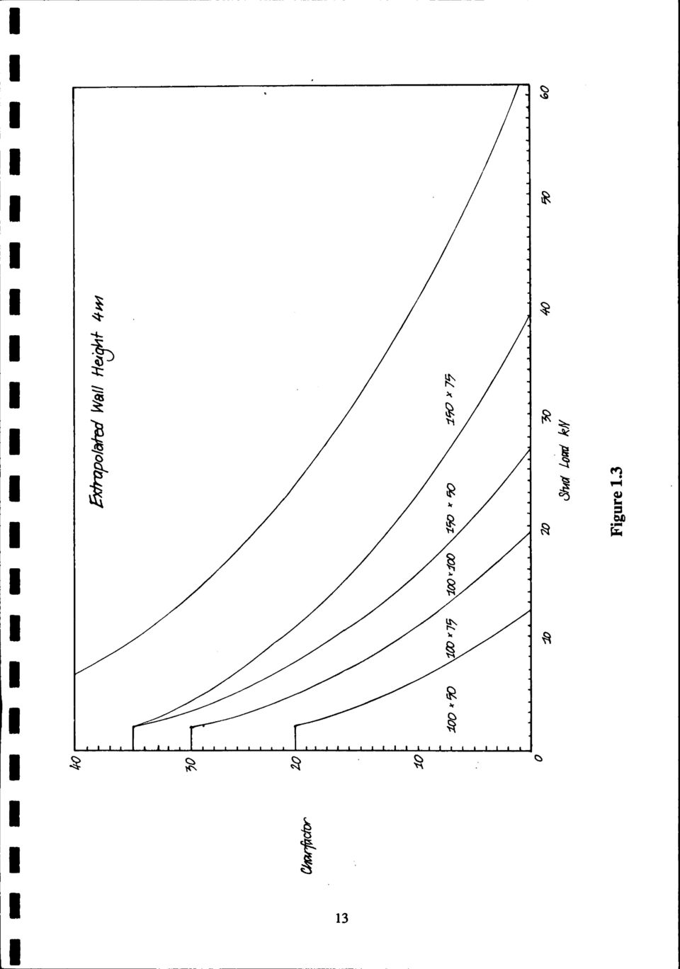
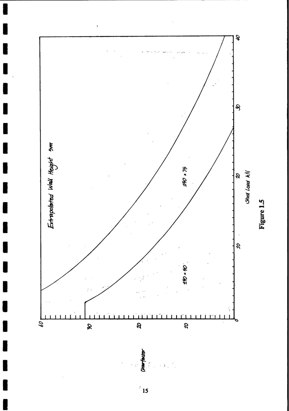
2 Contents Design of Light Timber Framed Walls and Floors for Fire Resistance Relevance Acceptance Scope of Application Walls Floors General Rules for Testing Prototypes Specification Definitions General Rules for Extrapolation (1) Materials used in Extrapolated Walls and Floors (2) Construction of Extrapolated Walls and Floors Extrapolation Methods (1) Walls, Loadbearing and Non-loadbearing (2) Floors Example 1 : Loadbearing wall Example 2: Non-loadbearing wall Example 3: Floor Basis of Recommendations Relevant Documents Appendix 1 : Tables and Figures Table 1.1: Charfactors - Tested Wall Height 3 m Table 1.2: Charfactors - Tested Wall Height 4 m Figure 1.1: Extrapolated Wall Height 3 m Figure 1.2: Extrapolated Wall Height 3.5 m Figure 1.3: Extrapolated Wall Height 4 m Figure 1.4: Extrapolated Wall Height 4.5 m Figure 1.5: Extrapolated Wall Height 5 m Figure 2.1 : Single Top Plates Figure 2.2: Double Top Plates Page

3 DESIGN OF LIGHT TIMBER FRAMED WALLS AND FLOORS FOR.. FIRE RESISTANCE RELEVANCE Walls and floors are required in some buildings to comply with New Zealand building code. requirements for fire resistance. Sometimes these can be of light timber framed construction.. Fire resistance of an element of construction is usually established by testing on a full sized prototype of the element. However, due to limitations on size and loading capacity of the testing equipment, and the cost of testing all possible combinations, it is often impractical to test the desired construction. The methods of extrapolation described here relate to light timber framed wall and floor constructions respectively which are similar to a tested wall or floor prototype. Some limitations are imposed by the design methods as follows: - walls or floors must be lined with the same lining materials as the tested prototype - changes are permitted to the heights of walls and spans of floors - changes are permitted to the loads imposed on walls - for floors, the loading may be reduced but not increased ACCEPTANCE It is recommended that elements of construction designed in accordance with the extrapolation methods specified in this document be accepted as a means of compliance with New Zealand building code requirements. SCOPE OF APPLICATION There are two extrapolation methods described here which apply to the design of light timber framed walls and floors respectively. Using the results from a floor or wall prototype test, these methods enable designers to produce a wall or floor having at least the same structural fire resistance as the original prototype. These methods cannot be used to increase the fire resistance of tested designs.. : These extrapolation methods are not intended to replace any accepted design method or code based on normal service criteria, including wind and earthquake etc. Therefore, designs produced by these methods should still be checked for compliance with other relevant service criteria. Walls The extrapolation method for wall design applies to any wall, of timber framed construction, either loadbearing or non-loadbearing, lined on both sides with a protective membrane fixed

4 directly to the framing, which has been tested in prototype in accordance with a standard fire resistance test. The extrapolation method for floor design applies to any loadbearing floor system lined on the underside with a protective membrane fixed directly to the timber framing, which has been tested in prototype in accordance with a standard fire resistance test. General Rules for Testing Prototypes To obtain maximum use of results from a prototype test, and avoid some of the restrictions discussed later, the following guidelines for selecting prototype parameters should be followed: test to the minimumdepth of stud orjoist that is expected to be required, i.e., the minimum gap between linings. test to the minimum width of stud or joist that is expected to be required. test to the maximum stud or joist spacing that is expected to be required. dwangs to be included at the maximum spacing required in the extrapolated system (see below). top plates to be included if required in extrapolated design, and these shall be point-loaded between studs to simulate floor joists. framing timber shall be dried to not greater than 16% moisture content. floors shall be tested to the maximum stress that is expected to be required in future extrapolations. walls shall be loaded so that the prototype fails by structural collapse, otherwise an unnecessarily conservative extrapolation will result. SPECIFICATION Definitions Unless otherwise stated, terms are consistent with those used in NZS 1900 Chapter 5, NZS 3603 and NZS EXPOSED SIDE is.the face of a test specimen that is exposed to the fire. FIRE RESISTANCE is the time (minutes) to failure under one of the relevant criteria of the fire resistance test standard as defined in NZS 1900 Chapter 5.

5 FIRE RESISTANCE RATING (FRR) is a rating (in hours) assigned to a particular element of construction which resists fire. This is usually based on the FIRE RESISTANCE of a prototype construction. UNEXPOSED SIDE is the face of a fire resistance test specimen not exposed to fire. General Rules for Extrapolation These general rules are in addition to the specific rules set out in the Extrapolation Methods section for each particular type of element. (1) Materials used in Extrapolated Walls and Floors The materials used for framing, lining and insulating the construction shall be at least equivalent in terms of their response to fire to those used in the tested prototype. Framing - Timber of the same species to be of the same or greater density. Lining - - Timber to be of the same grade or better. - Timber of another species to be of higher average density. Gypsum plasterboard to be of the same grade, equal or greater thickness, and from the same manufacturing specification. - Wood-based sheet linings to be of the same formulation, and equal or greater thickness and density. - Sprayed or mineral fibre protection to be the same product and density, and of equal or greater thickness. - Other sheet lining materials to be of same composition and density, and equal or greater thickness, and from the same manufacturer. - Other linings to be the same type, density and equal or greater thickness as used in the test specimen. Insulation - Insulation included in the wall or floor cavity for acoustic control andfor thermal insulation, is to be from the same manufacturer, of the same type, thickness, density and rating as used in the test specimen. This also means that insulation cannot be added to an extrapolated design, unless it was included in the tested prototype, and vice versa. (2) Construction of Extrapolated Walls and Floors Framing - Studs and joists to be at the same or closer spacings than those in the tested prototype.
 Materials used in Extrapolated Walls and Floors The materials used for framing, lining and insulating the construction shall be at least equivalent in terms of their response to fire to those")
6 - Studs and joists not to be smaller in either cross-section dimension than in the tested prototype. - Dwangs shall be included in both the prototype andextrapolatedconstruction. The spacing between dwangs in-the extrapolated wall cannot be greater than that used in the protoype and shall be in accordance with the following table. I Lining as for protoype The dwangs are required to provide restraint against lateral deflection of the studs and provide at least an equivalent security of fixing for the exposed lining as in the prototype test. - Sheet linings shall be fixed in exactly the same manner as in the test specimen, i.e., using nails or screws of the same type, diameter and penetration into framing, and at the same spacing. - Each individual sheet shall beof the same or greater size than in the test specimen. - All sheet joints shall be formed over timber framing members, unless other jointing techniques were used in the tested prototype. - Linings other than sheet linings shall be applied in the same manner as in the tested prototype. Insulation - Shall be fixed in a similar manner to that used in the tested prototype and located so the air gap between the insulation and lining on either side is not less than for the tested prototype. If the insulation is expected to provide some fire protection to the timber framing, then allowance for the same degree of protection should be made in the extrapolated construction. Extrapolation Methods (1) Walls, Loadbearing and Non-loadbearing The fie resistance determined by test for a loadbearing timber framed wall may be applied to a wall of similar construction, at a different width, height and/or load, subject to the general rules listed above, and using the extrapolation method set out below. 1. Using Table 1.1 or 1.2, depending on whether the tested prototype was 3 m or 4 m in height, determine the "charfactor" for the tested stud size and load (in kn per stud) at structural failure. It is permitted to interpolate between loads to determine the charfactor. In non-loadbearing walls the stud load is considered to be zero; in this case the method only applies to walls less than or equal to 1 hour fire resistance.

7 For a non-loadbearing prototype wall which does not fail structurally, aconservative extrapolation can be avoided if some judgement on the likely charfactor is exercised. The testing laboratory can make an assessment of the charfactor from the recorded test data and an inspection of the specimen at the conclusion of the test, provided it was extinguished in time. If it is not possible to determine a charfactor, e.g., when studs of the prototype test wall have been completely consumed by charring and only the lining remains, this method is then not applicable. The results of non-loadbearing wall tests can only be extrapolated to other non-loadbearing walls. Sometimes it may be preferable to use a loaded prototype test result for extrapolation to a nonloadbearing wall. 2. From Figures 1.1 to 1.5 select the new wall height. 3. Use the charfactor to determine a new stud size or stud load for the extrapolated wall. Check that neither of the cross-section dimensions of the stud have been reduced in the extrapolation process from the tested prototype stud dimension. If a reduced dimension is indicated a larger stud size shall be chosen to satisfy the general rules under "construction of extrapolated walls and floors" (see above). 4. If the stud size determined is unavailable, it may be substituted for one capable of bearing a greater load. Composite studs can be used, two 100 x 50 mm studs nailed together can be substituted for a single 100 x 100 mm stud, provided the greater cross-section dimension is across the wall cavity. 5. If a loaded wall is supporting a floor above, and the top plate becomes a point loaded beam due to unequal spacing between floor joists and wall studs, a new top plate must be selected by using Figure 2.1 or 2.2. These Figures apply to a stud spacing of 600 mm between centres. For stud spacings of 480 mm and 400 mm, the permitted load per stud may be increased by factors of 1.25 and 1.5 respectively. 6. Check the extrapolated design so that it complies with the relevant design code for the service required, and the maximum permissible stresses are not exceeded. (2) Floors The result of a fire resistance test on a loadbearing floor system may be applied to a floor of a similar construction subject to the general rules set out above. Also, the calculated stress induced in critical areas of the extrapolated construction must not be greater than that in the test specimen. Example 1: Loadbearing wall A wall has been tested at a 3.0 m height using 100 x 50 mm studs at 600 mrn centres with a load per stud of 8 kn. A new wall is required 4.0 m in height with a stud load of 15 kn and 600 mm stud spacing. 1. The charfactor for the tested wall (determined from Table 1.1) at structural failure is The new height required is 4.0 m, so Figure 1.3 is used.

8 3. For a charfactor of 14 and load per stud of 15 kn, the new stud size is 150 x 50 mm. 4. From Figures 2.1 and 2.2, a new top plate is selected. Either a single 150 x 75 mm top plate or two 150 x 50 mm top plates are required to carry a stud load of 15 kn. The orientation of top plates is with the greater dimension in the same direction as that of the studs. Example 2: Non-Loadbearing Wall A non-loadbearing wall has been tested at a 3.0 m height using 100 x 50 mm studs at 600 mm centres. A new non-loadbearing wall is required 5.0 m in height. 1. The charfactor for the tested wall (determined from Table 1.1) at structural failure is The new height required is 5.0 m, so Figure 1.5 is used. 3. For a charfactor of 38 and zero load per stud, the new stud size is 150 x 75 mm. 4. The top plate can be the same cross-section dimensions as the stud. The above extrapolation could be considered very conservative. Assessment of the charfactor indicates a more likely value of 14, if example 1 was the prototype test. In this instance the extrapolated design derived from Figure 1.5 indicates a new stud size of 150 x 50 mm. Example 3: Floor A floor has been tested at a 4 m span using nominal 250 x 50 mm joists at 600 mm centres, with a load of 3 kpa. A new floor is required with a 5 m span and a 3 kpa load. Note that loads may be reduced for fire design in accordance with combinations given in the loadings code. 1. Determine the maximum stress in the joists Distributed load on the joist, w = Ps where: P = floor load in kpa s = joist spacing in metres Maximum bending moment, where, 1 = span of joist in metres M= y,y 8

9 Maximum stress in bending, f =M/Z. where section modulus, Z = - bd2 6"..,., where b = breadth of joist.. d = depth of joist Actual dimensions of joist, "dry green gauged" are 239 x 46 mm.. Therefore maximum stress f = 3.6 x lo3 Nm' 4.38 x lo4 m3-8.2 MPa 2. For the extrapolated floor, try reducing joist spacing to 400 mm and determine the joist size required. Distributed load on joist, Maximum bending moment w = Ps = 3kPax0.4m = 1.2 kn/m M= wp - 8 Maximum strength Therefore: The size of joist which satisfies this condition is determined as follows. If b = m (nominal 50 mm breadth) Then d2 > 0.06 m2 d > m (245 mm) The next actual depth of joist available is 288 mrn or 300 mm nominal.

10 So the size of joist required is 300 x 50 mm with actual dimensions of 288 x 46 mm and section modulus Z of 6.35 x lo4 m3. The new floor will have 300 x 50 joists at 400 mm spacings and a span of 5 m with a maximum load of 3 kpa. BASIS OF RECOMMENDATIONS This technical recommendation results from a research project which included six fire resistance tests on loaded light timber framed walls (Collier, 1991). Walls were designed specifically to study the structural failure mechanisms over a range of loads, stud size and wall height. In addition, numerous fire resistance tests have been caniedout by BRANZon light timber framed walls, both loadbearing and non-loadbearing, and on loadbearing timber framed floors. The extrapolation methods in this Technical Recommendation are based on an engineering evaluation of the results of these tests. Conservative assessment of fire resistance will result in all cases. RELEVANT DOCUMENTS NZS 3603:1990. Code of practice for timber design. NZS 3604: Code of practice for light timber framed buildings not requiring specific design. NZS 1900 Chapter 5:1988. Fire resisting construction and means of egress. King, J.J Fi resistance testing of loaded timber floors. The New Zealand Journal of Timber Construction, 3(1): pp Collier P.C.R Design of light timber framed walls for fire resistance. BRANZ Study Report No. 36. Judgeford.

11 Table 1.1 Charfactors - Tested Wall Height 3 m

12 Table 1.2 Charfactors - Tested WaU Height 4 m

13

14

15
16

17
18 C HARFACTOR Figure 2.1 Single Top Plates 16

19 CHARFACTOR Figure 2.2 Double Top Plates

20 1991 Design of light timber fr amed walls and floors for

21 THE RESOURCE CENTRE FOR BUILDING MCEUENCE BRANZ MISSION To promote better building through the application of acquired knowledge, technology and expertise. HEAD OFFICE AND RESEARCH CENTRE Moonshine Road, Judgeford Postal Address -Private Bag 50908, Porirua Telephone - (04) , FAX - (04) REGIONAL ADVISORY OFFICES AUCKLAND Telephone - (09) FAX - (09) Great South Road PO BOX Greenlane WELLINGTON Telephone - (04) FAX - (04) Moonshine Road, Judgeford CHRISTCHURCH Telephone - (03) FAX - (03) GRE Building Hereford Street PO Box 496
Report Number BTC 17755F
 Leics. LE NP Tel () 4 Fax () 4 Email btc.testing@saintgobain.com Report Number BTC 77F A FIRE RESISTANCE TEST ON A LOADBEARING TIMBER JOIST FLOOR INCORPORATING 4mm x 7mm x 47mm SOLID JOISTS PROTECTED BY
Fire safety in timber buildings
 Fire safety in timber buildings Introduction Fire spread in buildings is a risk to life safety for which the Building Regulations (for England and Wales 1,2, Scotland 3 and Northern Ireland 4 ) aims to
Structural fire design Eurocode 5-1.2 Timber structures
 Background and Applications Brussels, 18-20 February 2008 Dissemination of information workshop 1 Structural fire design Eurocode 5-1.2 Timber structures Jochen Fornather Austrian Standards Institute jochen.fornather@on-norm.at
Fire and Acoustic. Design Manual. October 2010 / New Zealand
 Fire and Acoustic Design Manual October 2010 / New Zealand 1 Contents 2 Introduction 3 3 Application and scope 3 3.1 Application 3 3.2 Scope 3 3.3 Responsibility 3 4 System index 5 5 How to use this manual
Fire 2This Technical Bulletin has been commissioned by the UK SIP Association in
 REV 1-12.12.11/TB002 Technical Bulletin Fire 2This Technical Bulletin has been commissioned by the UK SIP Association in conjunction with TRADA Technology and is intended to provide the reader with introductory
Requirements for Fire Protection of Light Weight Floor Systems **Act 1 Revisited**
 PHRC Webinar Series Tuesday, September 9, 2014 1:00 pm Requirements for Fire Protection of Light Weight Floor Systems **Act 1 Revisited** Presented by: Bryan Heitzmann Credit(s) earned on completion of
CERTIFICATE NAME OF PRODUCT MANUFACTURER PRODUCT DESCRIPTION CERTIFICATION PROCEDURE. No VTT C-6044-10 Date of issue 11.10.2010, Updated July 1, 2011
 CERTIFICATE NAME OF PRODUCT No VTT C-6044-10 Date of issue 11.10.2010, Updated July 1, 2011 H-CONTROL REFLEX+ reflective insulating vapour control layer for roof and wall applications MANUFACTURER ACTIS
Post and Beam Construction
 Post and Beam Construction A Presentation By the Canadian Wood Council Canadian Conseil Wood canadien Council du bois Early settlers introduced the concept of post and beam construction in North America
FIRE PERFORMANCE OF STRUCTURAL INSULATED PANEL SYSTEMS
 INFORMATION PAPER IP 21/10 FIRE PERFORMANCE OF STRUCTURAL INSULATED PANEL SYSTEMS Tom Lennon and Danny Hopkin The use of Structural Insulated Panel (SIP) systems in construction in the UK has increased
Timber Decks. Technical Note. March 2007
 Timber Decks Technical Note. March 2007 This Technical Note contains general information for residential timber decks and floor frame structures for veranda s, patios etc which are exposed to the weather.
Timber frame structures platform frame construction (part 1)
") Timber frame structures platform frame construction (part 1) Introduction The platform frame method of building timber frame structures is suited to both low-rise and medium-rise buildings. Many buildings
Timber frame structures platform frame construction (part 1) Introduction The platform frame method of building timber frame structures is suited to both low-rise and medium-rise buildings. Many buildings
The better way to build TM. Installation Manual. EXTERIOR WALL SIPs
 The better way to build TM Installation Manual EXTERIOR WALL SIPs July 2015 EXTERIOR WALL SIPs Installation Manual Table of Contents Topics General Requirements................................... 3 Materials..............................................
PASSIVE FIRE PROTECTION SYSTEMS Application & Technical Manual: Ceilings & Floors
 PASSIVE FIRE PROTECTION SYSTEMS Application & Technical Manual: Ceilings & Floors For distribution in Asia Pacific PASSIVE FIRE PROTECTION SYSTEMS Application & Technical Manual: Ceilings & Floors Contents
CITY OF LOS ANGELES CALIFORNIA
 BOARD OF BUILDING AND SAFETY COMMISSIONERS VAN AMBATIELOS PRESIDENT E. FELICIA BRANNON VICE-PRESIDENT JOSELYN GEAGA-ROSENTHAL GEORGE HOVAGUIMIAN JAVIER NUNEZ CITY OF LOS ANGELES CALIFORNIA ERIC GARCETTI
HOOVER TREATED WOOD PRODUCTS, INC. TECHNICAL NOTE FOR ADDITIONAL INFORMATION: 1-800-TEC-WOOD (832-9663)
") HOOVER TREATED WOOD PRODUCTS, INC. TECHNICAL NOTE FOR ADDITIONAL INFORMATION: 1-800-TEC-WOOD (832-9663) Fire-Retardant-Treated Wood Framed Wall Assemblies GENERAL INFORMATION Fire-resistant construction
HOOVER TREATED WOOD PRODUCTS, INC. TECHNICAL NOTE FOR ADDITIONAL INFORMATION: 1-800-TEC-WOOD (832-9663) Fire-Retardant-Treated Wood Framed Wall Assemblies GENERAL INFORMATION Fire-resistant construction
Contents. APA Construction Details. Full fill cavity walls 2-13. Partial fill cavity walls 14-25. Solid externally insulated walls 26-37
 Contents Pages Full fill cavity walls 2-13 Partial fill cavity walls 14-25 Solid externally insulated walls 26-37 Appendix (BRE confirmation of Ψ and y-values) 38-40 Page 1 of 40 APA Construction Details
December 2013. J-Ply Roofing, Flooring and Decking
 December 2013 J-Ply Roofing, Flooring and Decking Introduction J-Ply plywood is manufactured in New Zealand by Juken New Zealand Limited (JNL) and marketed by New Zealand Wood Products Limited. The J-Ply
Document type: Practice Note Title: External and internal membranes Document number: AC2234 Version: 5. 1. Purpose
 Document type: Practice Note Title: External and internal membranes Document number: AC2234 Version: 5 1. Purpose The purpose of this practice note is to address the incidence of deck and roof membrane
CERTIFICATE OF APPROVAL No CF 5055 ARABIAN VERMICULITE INDUSTRIES
 CERTIFICATE OF APPROVAL No CF 5055 This is to certify that, in accordance with TS00 General Requirements for Certification of Fire Protection Products The undermentioned products of 1 st Industrial Area,
Fire-resistant barriers: background on requirements and determination method. Reading guide for test reports.
 Fire-resistant barriers: background on requirements and determination method. Reading guide for test reports. Report number C 1395-1E-RA-003 d.d. May 14, 2014 Fire-resistant barriers: background on requirements
Compression load testing straw bale walls. Peter Walker Dept. Architecture & Civil Engineering University of Bath Bath BA2 7AY.
 Compression load testing straw bale walls Peter Walker Dept. Architecture & Civil Engineering University of Bath Bath BA2 7AY May 2004 1. Introduction Over the last 10 years a growing number of loadbearing
STRUCTURAL CONCEPT FOR LIGHT GAUGE STEEL FRAME SYSTEM
 Chapter 9 STRUCTURAL CONCEPT FOR LIGHT GAUGE STEEL FRAME SYSTEM 9.1 BACKGROUND Steel is widely used in the construction of multi-storey buildings. However, steel construction is seldom used and is traditionally
IRISH BUILDING CONTROL INSTITUTE HOTEL COURT HOTEL BALLYCONNELL CO CAVAN. 26 th MARCH 2009 TIMBER FRAME CONSTRUCTION
 IRISH BUILDING CONTROL INSTITUTE HOTEL COURT HOTEL BALLYCONNELL CO CAVAN 26 th MARCH 2009 TIMBER FRAME CONSTRUCTION Bill Robinson BSc. C. Eng. M. I. Struct. E. Timber Design Services 1 IS440 Timber frame
Eurocode 5: Design of timber structures
 Eurocode 5: Design of timber structures Arnold Page, BSc, BD, MIWSc. Structural timber engineering consultant Introduction BS EN 1995 consists of three parts: Part 1-1: General. Common rules and rules
LPCB Red Book Listed Products and Passive Fire Protection Installer Schemes Answering the needs of the market
 LPCB Red Book Listed Products and Passive Fire Protection Installer Schemes Answering the needs of the market Ian Stewart Passive installer scheme manager September 2011 Introduction to BRE Global Research,
MECHANICS OF SOLIDS - BEAMS TUTORIAL 1 STRESSES IN BEAMS DUE TO BENDING. On completion of this tutorial you should be able to do the following.
 MECHANICS OF SOLIDS - BEAMS TUTOIAL 1 STESSES IN BEAMS DUE TO BENDING This is the first tutorial on bending of beams designed for anyone wishing to study it at a fairly advanced level. You should judge
H-Stud Area Separation Wall System
 12 TH EDITION 09 21 16.33/NGC H-Stud Area Separation Wall System 09 21 16.33 139 H-STUD AREA SEPARATION WALL SYSTEM The fire-protection of gypsum-based Area Separation Walls is demonstrated in dramatic
Discipline: Structural Issued 04-26-06
 California Department of General Services. Division of the State Architect. Product Acceptance Report STRUCTURAL SHEAR PANEL SURE-BOARD SERIES 200 PANELS PA-132 Discipline: Structural Issued 04-26-06 This
DESIGNERS GUIDE TO DOMESTIC CONSERVATORIES
 WBCA 403 DESIGNERS GUIDE TO DOMESTIC CONSERVATORIES A guide to assist those intending to install or who are involved in installing conservatories. Includes information about: conservatory and component
Property Inspection. 83A Ascot Avenue North New Brighton Christchurch STRUCTURAL REPORT
 Property Inspection 83A Ascot Avenue North New Brighton Christchurch STRUCTURAL REPORT March 2013 This document has been prepared for the benefit of Clint Marston. No liability is accepted by this company
How To Certify The Scottsdale Construction System
 BRE CERTIFICATION LIMITED PRODUCT SCOTTSDALE CONSTRUCTION SYSTEM CERTIFICATE NUMBER 129/07 DATE OF ISSUE December 2007 SUPPLIED BY Scottsdale Construction System Ltd SUMMARY The Scottsdale Construction
FLASHMAN WINDOW AND DOOR FLASHING SYSTEM. Product. Scope. Appraisal No. 573 [2013]
![FLASHMAN WINDOW AND DOOR FLASHING SYSTEM. Product. Scope. Appraisal No. 573 [2013]](/thumbs/40/20900857.jpg "FLASHMAN WINDOW AND DOOR FLASHING SYSTEM. Product. Scope. Appraisal No. 573 [2013]") FLASHMAN WINDOW AND DOOR FLASHING SYSTEM This Appraisal replaces BRANZ Appraisal No. 573 (2007). Amended 05 February 2016. BRANZ Appraisals Technical Assessments of products for building and construction.
FLASHMAN WINDOW AND DOOR FLASHING SYSTEM This Appraisal replaces BRANZ Appraisal No. 573 (2007). Amended 05 February 2016. BRANZ Appraisals Technical Assessments of products for building and construction.
Rockwool Flexi Insulation Application Guide
 Pitched roof Rafters InterMediate floors INTERNAL partitions external Framed walls separating floors Separating Walls Rockwool Flexi Insulation Application Guide Ground floor The perfect fit for any framed
Insulated Roof & Wall Panels. Product Data Sheet. Trapezoidal Insulated Roof Panels KS1000 RW
 Insulated Roof & Wall Panels Trapezoidal Insulated Roof Panels KS1000 RW Overview Kingspan roof panel systems present a superior system compared to conventional multi-part site assembled systems. They
Good Craftsmanship Guide. Carpentry and Joinery- Carcassing
 Good Craftsmanship Guide Carpentry and Joinery- Carcassing Introduction This Good Craftsmanship Guide highlights key problems with the major elements of Carpentry and Joinery - Carcassing, and gives guidance
RESIDENTIAL PLUMBING ALTERATIONS PERMIT REQUIREMENTS
 RESIDENTIAL PLUMBING ALTERATIONS PERMIT REQUIREMENTS The following guidelines are intended to assist with the permit acquisition process with regard to Plumbing Alterations. Not all information, or additional
Partitioning & Ceiling Product Information
 Partitioning & Ceiling Product Information tel + 44 (0) 1384 412448 fax + 44 (0) 1384 4494 email enquiries@drywallsteelsections.co.uk web www.drywallsteelsections.co.uk tel + 44 (0) 1384 412448 fax + 44
ICC-ES Evaluation Report
 ICC-ES Evaluation Report ESR-2369 Reissued May 1, 2010 This report is subject to re-examination in one year. www.icc-es.org (800) 423-6587 (562) 699-0543 A Subsidiary of the International Code Council
Connection Solutions
 Connection Solutions DESIGN BUILD SYSTEM Connection Solutions for Cold formed Steel Construction Complies with; AS/NZS 4600:2005 AISI S100:2007 AS/NZ 1397 ASTM A653 DESIGN & BUILD SYSTEM FRAMECAD Construction
GYPSUM AREA SEPARATION FIREWALLS GA-620-2011
 GYPSUM AREA SEPARATION FIREWALLS GA-620-2011 GA-620-2011 Copyright 2011 Gypsum Association All rights reserved. Printed in U.S.A. Characteristics, properties, or performance of materials or systems herein
Formwork for Concrete
 UNIVERSITY OF WASHINGTON DEPARTMENT OF CONSTRUCTION MANAGEMENT CM 420 TEMPORARY STRUCTURES Winter Quarter 2007 Professor Kamran M. Nemati Formwork for Concrete Horizontal Formwork Design and Formwork Design
Uncovered Decks & Porches
 Uncovered Decks & Porches Building Guides for Homeowners Why Do I need a Permit? D I D Y O U K N O W? As owner-builder you are the responsible party of record on such a permit. If your work is being performed
Page & Turnbull imagining change in historic environments through design, research, and technology
 DCI+SDE STRUCTURAL EVALUATIONS OFFICE BUILDING, TOOL SHED & WATER TANK, AND BLACKSMITH & MACHINE SHOP BUILDINGS SAN FRANCISCO, CALIFORNIA [14290] PRIMARY PROJECT CONTACT: H. Ruth Todd, FAIA, AICP, LEED
INTERNATIONAL ASSOCIATION OF CLASSIFICATION SOCIETIES. Interpretations of the FTP
 INTERNATIONAL ASSOCIATION OF CLASSIFICATION SOCIETIES Interpretations of the FTP CONTENTS FTP1 Adhesives used in A or B class divisions (FTP Code 3.1, Res A.754 para. 3.2.3) June 2000 FTP2 Pipe and duct
Best Practice in Best Pra ctice in teel constr uction - onstr industrial B uildings esidential Buildings 01 Introduction 02 Key Design Factors
 Best Practice in Steel Construction - Industrial Residential Buildings Contents The Steel Construction Institute (SCI) develops and promotes the effective use of steel in construction. It is an independent,
The following sketches show the plans of the two cases of one-way slabs. The spanning direction in each case is shown by the double headed arrow.
 9.2 One-way Slabs This section covers the following topics. Introduction Analysis and Design 9.2.1 Introduction Slabs are an important structural component where prestressing is applied. With increase
Firewalls. By Gary Sturgeon, B.Eng., MSc., P.Eng. Technical Services Engineer, CCMPA. w w w. c c m p a. c a 5A-0
 By Gary Sturgeon, B.Eng., MSc., P.Eng. Technical Services Engineer, CCMPA 5A-0 This Chapter of the CCMPA Metric Technical Manual has been largely reproduced from Firewalls, A Design Guide, published by
The University of Birmingham (Live System)
") The University of Birmingham (Live System) Behaviour of Structural Insulated Panels (SIPs) under both short-term and long-term loadings Yang, Jian; Rungthonkit, Prathan Document Version Author final version
The University of Birmingham (Live System) Behaviour of Structural Insulated Panels (SIPs) under both short-term and long-term loadings Yang, Jian; Rungthonkit, Prathan Document Version Author final version
Fire Resistance of Brick Masonry
 TECHNICAL NOTES on Brick Construction 1850 Centennial Park Drive, Reston, Virginia 20191 www.gobrick.com 703-620-0010 Fire Resistance of Brick Masonry 16 March 2008 Abstract: This Technical Note presents
Section 3.1.2. Timber Frame Walls. Single layer between studs. Single layer between studs with service void. Between studs with insulated lining
 Section Timber Frame Walls Single layer between studs Product: Earthwool FrameTherm Rolls and Slabs Tf01 Single layer between studs with service void Product: Earthwool FrameTherm Rolls and Slabs Tf02
Installation Details. D1 General D2 Walls D3 Ceilings D4 Reference. D Installation Details
 D Installation Details D1 General D2 Walls D3 Ceilings D4 Reference D Installation Details D Contents D1 General Installation and Fastening Sequence for Steel Studs D1.1 Fastener Selection D1.3 D2 Walls
Bracing Webs in Trusses that have Dissimilar Configurations
 Bracing Webs in Trusses that have Dissimilar Configurations Released April 25, 2006 Issue: Truss Design Drawings (TDD) that are prepared in accordance with ANSI/TPI 1, National Design Standard for Metal
NRG 75 CRF NRG GREENBOARD WALL SYSTEM
 NRG GREENBOARD WALL SYSTEM NRG Energy Efficient Building Systems is pleased to announce a revolution in lightweight cladding systems. NRG Building Systems is the first and only company to achieve CodeMark
Section 5.0. Basements. Wall insulated externally. Wall insulated internally. Ba02. Product: Polyfoam ECO Floorboard Ba01.
 Section 5.0 Basements Wall insulated externally Product: Polyfoam ECO Ba01 Wall insulated internally Product: Polyfoam ECO Ba02 Basements Basements Basement design Waterproofing BS 8102: 2009 Code of practice
European Technical Approval ETA-12/0500
 ETA-Danmark A/S Kollegievej 6 DK-2920 Charlottenlund Tel. +45 72 24 59 00 Fax +45 72 24 59 04 Internet www.etadanmark.dk Authorised and notified according to Article 10 of the Council Directive 89/106/EEC
HURRICANE MITIGATION RETROFITS FOR EXISTING SITE-BUILT SINGLE FAMILY RESIDENTIAL STRUCTURES
 HURRICANE MITIGATION RETROFITS FOR EXISTING SITE-BUILT SINGLE FAMILY RESIDENTIAL STRUCTURES 101 Retrofits Required. Pursuant to Section 553.844 553.884, Florida Statutes, strengthening of existing site-built,
Fire Preventive and Fireproof Performance Test and Evaluation Procedure Manual
 BR BO-01-02 Effective from June 1, 2000 Revision: March 26, 2002 Fire Preventive and Fireproof Performance Test and Evaluation Procedure Manual (Unofficial Manual) Technical Appraisal Department, Building
ENVIRONMENTAL INFORMATION APR 1200 products are made from glass mineral wool, one of the most environmentally friendly insulants available.
 APR 1200 Acoustic Partition Roll CI/Sfb Ref: APR002 Glass mineral wool roll designed to provide high levels of sound insulation in walls and floors to meet Part E (England & Wales) and Section 5 (Scotland)
Fiberglas, Exterior Wall Thermal Insulation
 PROJECT ENGINEER RESPONSIBILITY: This is a general specification guide, intended to be used by experienced construction professionals, in conjunction with good construction practice and professional judgment.
The Homeowner s Building Application Checklist for Constructing a Residential Sundeck
 This checklist provides homeowners a summary of the Building Permit submission requirements for constructing a residential sundeck. Regardless of the deck s walking surface area, if the deck is adjacent
FireWall. High performance fireresistant. FireWall. www.british-gypsum.com
 FireWall FireWall High performance fireresistant wall system FireWall is a non-loadbearing wall which provides up to 240 minutes fire resistance. It is used in certain ground floor basement situations
RESIDENTIAL WOOD DECKS
 RESIDENTIAL WOOD DECKS 1 A Building Permit is required for the construction of a wood deck where the deck is more than 600 mm above grade at any point. Definition: For the purposes of this pamphlet, a
FINAL DRAFT FprEN 13381-2
 EUROPEAN STANDARD NORME EUROPÉENNE EUROPÄISCHE NORM FINAL DRAFT FprEN 13381-2 April 2014 ICS 13.220.50 Will supersede ENV 13381-2:2002 English Version Test methods for determining the contribution to the
Multi-layer Insulation Blanket for Roofs
 Multilayer Insulation Blanket for Roofs Thermal Insulation in a 40mm thin, flexible, multilayer membrane Meets requirements of L1A, L1B 2010 In accordance with BR443 NHBC Acceptance Pitched & Flat roof
Building Systems by Stora Enso. Residential multi-storey buildings
 Building Systems by Stora Enso Residential multi-storey buildings Table of contents 1 Introduction and disclaimer... 3 1.1 Introduction... 4 1.2 The benefits of the system... 5 1.3 Disclaimer... 5 2 Anatomy
4.3.5 - Breakaway Walls
 4.3.5 - Breakaway Walls Elevation of a structure on a properly designed foundation reduces the potential for water damage from flooding. When the space below the lowest elevated floor is maintained free
Residential Inspection Guidelines
 Residential Inspection Guidelines 201 Pre-Pour Foundation Dimensions Building Location Certificate - if required in the building consent Construction and Advice Notes Check the building dimensions against
METHODS FOR ACHIEVEMENT UNIFORM STRESSES DISTRIBUTION UNDER THE FOUNDATION
 International Journal of Civil Engineering and Technology (IJCIET) Volume 7, Issue 2, March-April 2016, pp. 45-66, Article ID: IJCIET_07_02_004 Available online at http://www.iaeme.com/ijciet/issues.asp?jtype=ijciet&vtype=7&itype=2
FERMACELL Powerpanel H 2 O for Wet & Moisture affected areas
 FERMACELL Powerpanel H 2 O for Wet & Moisture affected areas Powerpanel H 2 O is a cement based board from FERMACELL. Board Characteristics Board Thickness 12.5 mm Board Sizes 1000 x 1200 mm 50 sheets/pallet
IMPACT DAMAGE RESISTANT WALL SYSTEMS
 IMPACT DAMAGE RESISTANT WALL SYSTEMS CONTENTS Introduction 2 Advantages 2 2 Material Specifications 2 Design Considerations 3 Framing 5 Plasterboard Installation 5 Health, Safety & Warranty 6 Contact Details
Chapter 6 ROOF-CEILING SYSTEMS
 Chapter 6 ROOF-CEILING SYSTEMS Woodframe roof-ceiling systems are the focus of this chapter. Cold-formed steel framing for a roof-ceiling system also is permitted by the IRC but will not be discussed;
The Case for Cross Laminated Timber: Part 2
 Learning Objectives The Case for Cross Laminated Timber: Part 2 Opportunities and Challenges for a New Class of Timber Product 1. Review answers to common questions regarding the design and construction
LEGACY REPORT. www.icc-es.org (800) 423-6587 (562) 699-0543 A Subsidiary of the International Code Council. *Corrected March 2014
 423-6587 (562) 699-0543 A Subsidiary of the International Code Council. *Corrected March 2014") ICC-ES Legacy Report PFC-3700* Issued October 2003 www.icc-es.org (00) 423-57 (52) 99-0543 A Subsidiary of the International Code Council Legacy report on the 1997 Uniform Building Code and the 2000 International
ICC-ES Legacy Report PFC-3700* Issued October 2003 www.icc-es.org (00) 423-57 (52) 99-0543 A Subsidiary of the International Code Council Legacy report on the 1997 Uniform Building Code and the 2000 International
PB301 July 2009. Lightweight Building Solutions. Bushfire Protection. www.boral.com.au/bushfireprotection
 PB301 July 2009 Lightweight Building Solutions Bushfire Protection www.boral.com.au/bushfireprotection Attached or adjacent within 6m roofed structures such as garages, carports, verandas and the like,
Aluminium systems profile selection
 Aluminium systems profile selection The purpose of this document is to summarise the way that aluminium profile selection should be made, based on the strength requirements for each application. Curtain
PART 1 GENERAL 1.1 SECTION INCLUDES
 J-1 Section 09110 Long Form Specification INTERIOR METAL STUD FRAMING This section includes lightweight, usually 0.036 inch (0.9 mm) thick or lighter, non-axial load bearing metal stud framing including
The WANZ Guide to Window Installation
 The WANZ Guide to Window Installation as described in E2/AS1 Amendment 5 Ver. 1.1 Page 2 of 74 Contents Overview Page 5 Objective Page 5 Scope Page 5 Opening Preparation Page 7 Step P1 Preliminary Check
Optimum proportions for the design of suspension bridge
 Journal of Civil Engineering (IEB), 34 (1) (26) 1-14 Optimum proportions for the design of suspension bridge Tanvir Manzur and Alamgir Habib Department of Civil Engineering Bangladesh University of Engineering
This handout is a guide only and does not contain all of the requirements of the Minnesota State Building Code or city ordinances.
 Basement Finishing Guide Community Development Department Building Inspections Division 5200 85 th Avenue North / Brooklyn Park, MN 55443 Phone: (763) 488-6379 / Fax: (763) 493-8171 6/15 www.brooklynpark.org
ENGINEERING SCIENCE H1 OUTCOME 1 - TUTORIAL 3 BENDING MOMENTS EDEXCEL HNC/D ENGINEERING SCIENCE LEVEL 4 H1 FORMERLY UNIT 21718P
 ENGINEERING SCIENCE H1 OUTCOME 1 - TUTORIAL 3 BENDING MOMENTS EDEXCEL HNC/D ENGINEERING SCIENCE LEVEL 4 H1 FORMERLY UNIT 21718P This material is duplicated in the Mechanical Principles module H2 and those
European Technical Approval ETA 13/0526
 European Technical Approval ETA 13/0526 Trade Name Holder of the approval Website Generic type and use of construction product DOLCEA i3 PCIM S.A. Rue du Péquet 54 5590 Achene (Ciney) Belgium www.isoproc.eu
Timber Frame Walls Rethinking Construction
 Insulation Fifth Issue November 2007 Timber Frame Walls Rethinking Construction INSULATION BEST PRACTICE FOR THE 21ST CENTURY Summary 9 mm OSB sheathing 3 mm skim coated 15 mm plasterboard Rock or glass
Fire Protection. CANADIAN STEEL CONSTRUCTION COUNCIL 201 Consumers Road, Suite 300 Willowdale, Ontario, M2J 4G8. Floor Assembly No.
 BULLETIN No. 28 (a) Fire Protection CANADIAN STEEL CONSTRUCTION COUNCIL 201 Consumers Road, Suite 300 Willowdale, Ontario, M2J 4G8 Floor Assembly No. NRC764-FF22 Fire Endurance Period 1 74 minutes Sound
INSTALLATION. General. Important Note. Design. Transport
 General The roof trusses you are about to install have been manufactured to precise engineering standards. To ensure that the trusses perform as designed, it is essential that they be handled, erected
SECTION 08 41 1 ALUMINUM FRAMED ENTRANCES and STOREFRONTS. System 402 Flush-Glazed Screw Spline Storefront
 PART 1 GENERAL 1.01 Work Included SECTION 08 41 1 ALUMINUM FRAMED ENTRANCES and STOREFRONTS System 402 Flush-Glazed Screw Spline Storefront A. Furnish and install aluminum architectural storefront system
2015 UCC Residential Code Update
 2015 UCC Residential Code Update The Pennsylvania regulations related to Residential Construction codes changed effective January 1, 2016. The sections of the 2015 IRC that PA adopted as part of the UCC
6 RETROFITTING POST & PIER HOUSES
 Retrofitting Post & Pier Houses 71 6 RETROFITTING POST & PIER HOUSES by James E. Russell, P.E. 72 Retrofitting Post & Pier Houses Retrofitting Post & Pier Houses 73 RETROFITTING POST AND PIER HOUSES This
Energy Company Obligation (ECO): Technical Monitoring Questions
: Technical Monitoring Questions") Energy Company Obligation (ECO) Technical Monitoring Questions v1 30/05/2013 Energy Company Obligation (ECO): Technical Monitoring Questions Under ECO suppliers are required to instruct suitably qualified
Energy Company Obligation (ECO) Technical Monitoring Questions v1 30/05/2013 Energy Company Obligation (ECO): Technical Monitoring Questions Under ECO suppliers are required to instruct suitably qualified
STANDARD OPEN PATIO COVER
 STANDARD OPEN PATIO COVER BUILDING & SAFETY DIVISION 201 E. LA HABRA BLVD. LA HABRA, CA 90631 62-90-9710 Call Before You Dig 1-800-227-2600 PLEASE NOTE: This information Bulletin is made available to assist
INTERIOR WALLS AND BASEMENTS CHOOSING THE RIGHT MEMBRANE FOR INTERIOR WALLS. Multi-Layer Technology provides increased strength.
 INTERIOR WALLS AND BASEMENTS CHOOSING THE RIGHT MEMBRANE FOR INTERIOR WALLS Multi-Layer Technology provides increased strength. Specifically designed for interior applications. Compatible with most internal
Excerpts from the Canadian National Building Code (NBC)
") Excerpts from the Canadian National Building Code (NBC) Reproduced here with Permission of the Copyright Owner, the National Research Council of Canada, Institute for Research in Construction. For more
Excerpts from the Canadian National Building Code (NBC) Reproduced here with Permission of the Copyright Owner, the National Research Council of Canada, Institute for Research in Construction. For more
B. Related categories: The following categories contain requirements that relate to this section:
 ORIENTED STRAND BOARD PART I. - GENERAL 1.1 RELATED DOCUMENTS A. Drawings and general provisions of Contract, including General and Supplementary Conditions and Division 1 Specification Sections, apply
Design guide. Part 1: Structural Design
 Design guide Part 1: Structural Design Design guide Part 1: Structural Design Advantages: Fast Economical Strong Insulating Environmentally friendly Versatile Modernist house supplied by SIPBuild Vernacular
SOUND INSULATION FOR EXTERIOR WALLS AND FACADE SYSTEMS
 NOISE TECHNICAL FACT SHEET FACT SHEET 5 SOUND INSULATION FOR EXTERIOR WALLS AND FACADE SYSTEMS The sound insulation of exterior walls and roof-ceiling systems refers to their ability to reduce external
Building Construction. Lightweight construction. Conventional Construction
 Ventilation 53 Building Construction The firefighter s ability to safely and efficiently ventilate a building through its roof will depend to some degree on the firefighter s understanding of roof construction.
We care about. Environmentally-Friendly Building Products from Renewable Resources. natural building products. Product range overview
 http://upload.wikimedia.org/wikipedia/commons/a/ae/flag_of_the_united_kingdom.svg.0.0 :8 Seite von Environmentally-Friendly Building Products from Renewable Resources Product range overview We care about
Residential Deck Safety, Construction, and Repair
 Juneau Permit Center, 4 th Floor Marine View Center, (907)586-0770 This handout is designed to help you build your deck to comply with the 2006 International Residential Building code as modified by the
Timber Frame Construction
 Timber Frame Construction Introduction Design and Detailing What is timber? Failure modes History of timber frame construction Forms of timber frame construction Live and dead loads Wind loads Roof construction
Repairing storm damaged roofs
 Repairing storm damaged roofs Tie-down designs for tile and sheet roofs Conforms to wind classifications of up to category N3 (previously W41N) designed to withstand a maximum gust wind speeds of 50 metres