Part-IV Repair, Restoration and Seismic Retrofitting of Masonry Buildings
|
|
|
- Dinah Harrell
- 8 years ago
- Views:
Transcription
1 UN/DESA PROJECT INT/98/X70 (UNCRD) Contract No GUIDELINES FOR REPAIR, RESTORATION AND SEISMIC RETROFITTING OF MASONRY BUILDINGS Part-IV Repair, Restoration and Seismic Retrofitting of Masonry Buildings Dr. Anand S. Arya, FNA, FNAE Professor Emeritus Department of Earthquake Engineering Indian Institute of Technology, Roorkee, India UNCRD Kobe Office United Nations Centre for Regional Development Nagoya, Japan March 2003

2 PREFACE United Nations DESA, in consultation with United Nation Centre for Regional Development, Disaster Management Office Kobe, offered a Consultant Contract to the author for performing the following specific services.. To develop a guideline for earthquake safe construction with mud (new construction) and stone houses (both new construction and retrofitting) to be used by masons and house owners. 2. To develop training materials for use of engineers in the design and construction of masonry buildings of all types and detailing of reinforced concrete buildings for achieving adequate performance during earthquakes; 3. To develop a model design of earthquake safe school and a community center, using appropriate locally available materials with elements for its earthquake protection; 4. To provide advisory services during the training of engineers in Kabul, Afghanistan, and; 5. To submit a report to UNDESA-UNCRD, including the guidelines, training materials and model design. In order to fulfil the requirements of preparing the guidelines for earthquake safe construction including new constructions and retrofitting of masonary buildings as well as to develop training material for use of engineers in the design and construction of masonary buildings of all types and detailing of reinforced concrete buildings for achieving adequate performance during earthquakes, the Consultant has planned to prepared the guidelines in following five parts so that they could be conveniently used for various purposes of training and guidance. Part I Earthquake Resistant Design of Buildings Part II Earthquake Resistant Design and Construction of Rectangular Unit Masonry Buildings Part III Earthquake Resistant Construction of Stone Buildings Part IV Repair, Restoration and Seismic Retrofitting of Masonry Buildings Part V Earthquake Resistant Construction of Earthen Houses The present document is Part IV-Repair, Restoration and Seismic Retrofitting of Masonry Buildings. It covers the topic of restoration of lost strength of cracked masonry walls, cosmetic repair, as well as their seismic retrofitting. Methods of seismic retrofitting will equally apply to existing weak masonry buildings for upgrading their seismic safety in various seismic zones of Afghanistan. This part will be useful for providing training of the engineers as well as masons, and providing help in improving the safety of such building in future probable earthquakes. March 2003 A.S. Arya Consultant 2

3 CONTENTS PREFACE 2 CONTENTS 3. INTRODUCTION 4 2. OBJECT AND SCOPE 4 3. CATEGORISATION OF DAMAGE 5 4. CONCEPTS OF REPAIR, RESTORATION AND RETROFITTING 5 4. Repair Restoration Seismic Strengthening (Retrofitting) 7 5. ASSESSMENT OF DAMAGE 8 6. USUAL DAMAGE TYPES IN MASONRY BUILDINGS 8 7. METHODOLOGY FOR GROUTING OF CRACKS 8 7. Minor and Medium Cracks Major Crack 8. INSTALLING FERRO-CEMENT PLATES AT THE CORNERS 2 9. REBUILDING PORTIONS OF THE WALL 3 0. EARTHQUAKE RESISTANT RETROFITTING OF BUILDINGS 5. CONTROL ON LENGTH, HEIGHT, THICKNESS OF WALLS 5 2. CONTROL ON DOOR AND WINDOW OPENINGS IN MASONRY 8 3. MAKING THROUGH BOND ELEMENTS IN R.R. STONE WALL 9 4. PROVIDING HORIZONTAL SEISMIC BELTS Seismic Belt Location Description of Reinforcement in Belt 2 5. VERTICAL SEISMIC BELT AT CORNERS SEISMIC BELTS AROUND DOOR/WINDOW OPENINGS METHOD OF FIXING SEISMIC BELTS PROVIDING VERTICAL REINFORCEMENT AT CORNERS, 25 JUNCTIONS OF WALLS 9. STIFFENING THE FLAT WOODEN FLOOR/ROOF STIFFNING THE SLOPING ROOFS STRUCTURE 26 3

4 Part IV REPAIR, RESTORATION AND SEISMIC RETROFITTING OF MASONARY BUILDINGS. INTRODUCTION In the last twelve years, Afghanistan has suffered severe to moderate building damages from three earthquakes in 99, 998 and 2002 which killed in all, more than 0000 persons, in several villages. Besides, thousand of building have been damaged during two decades of civil strife in the country. Whereas there is need for reconstruction of collapsed or severely damaged buildings, repairing and retrofitting of moderately damaged buildings will be a time saving and economical option instead of their demolition and reconstruction. People are killed or badly injured during strong ground shaking in stone masonry buildings in villages as well as in towns because of the following contributing factors: a) poorly constructed buildings, collapsing either totally or partially; b) walls collapsing within narrow streets, burying people escaping into them; c) untied roofs and cantilevers falling onto people; d) free standing high boundary walls, parapets and balconies falling due to the sever shaking. Many times, buildings which are standing in damaged condition with cracks of minor to major width and extent, are repaired superficially, that is, with cosmetic repairs. When this is done, these buildings will remain very vulnerable to severe damage in future earthquakes due to the hidden cracks in the walls. The purpose of these guidelines is to address the issues of repair, restoration and seismic retrofitting of various types of masonry buildings. 2. OBJECT AND SCOPE These guidelines have the following objectives; (i) To indicate appropriate methods of repair and restoration taking into account the building type and the type of damage. 4

5 (ii) To recommend methods of seismic strengthening to upgrade the strength of the buildings in line with the requirements of the seismiczoning map of Afghanistan (See part I) and Earthquake Resistance Codes of India (IS : ) and (IS: ). The retrofitting measures are worked out here for safety of existing damaged or undamaged buildings in future MSK Intensity occurrences in the various seismic zones. The masonry buildings will include : Walls of brickwork, random rubble stone masonry and cut stone masonry whether used for housing or community buildings. 3. CATEGORISATION OF DAMAGE As specified usually in the MSK Intensity scale, five Grades of damage are recognized and named as G to G5; G referring to very slight damage without loss of structural strength and G5 referring to complete collapse of the building (See Table 4. in Part-I). Description of these Grades of damage as applicable to masonry buildings is presented in Table for ready reference. So far as repair, restoration of structural strength and seismic strengthening to meet the codal requirements are concerned, Grades G to G3 are most relevant, since buildings or parts thereof subjected to Grades G4 and G5 in most cases have to be demolished and rebuilt. 4. CONCEPTS OF REPAIR, RESTORATION AND RETROFITTING There is a need to distinguish between the terms repair, restoration and strengthening as described below: 4. Repair It consists of actions taken for patching up superficial defects, re-plastering walls, repairing doors and windows and services such as the following : i) Patching up of defects as cracks and fall of plaster and re-plastering if needed. ii) Repairing doors, windows and replacement of glass panes. 5

6 Table. Damage Grades* Category Walls * Roof / Floors 0 No Damage No Damage No Damage G Slight Non-Structural Thin cracks in plaster, falling of Thin cracks in small areas, Damage plaster bits in limited parts. tiles only slightly disturbed G2 Slight Structural Small cracks in walls, falling of Small cracks in slabs/ A.C. Damage plaster in large areas : damage sheets; tiles disturbed in to non-structural parts like about 0% area; minor chhajjas, parapets. damage in under-structure of sloping roof. G3 Moderate Structural Large and deep cracks in Large cracks inslabs; some Damage walls; widespread cracking of AC sheets, broken; upto 25% walls, columns and piers; or tiles disturbed/fallen collaps of one wall. The load moderate damage to carrying capacity of structure is understructure of sloping partially reduced. roofs. G4 Severe Structural Gaps occur in walls; two or Floors badly cracked, part Damage more inner or outer walls may fall; under- structure of collapse; Approximately fifty sloping roof heavily damaged, percent of the main structural part may fall; tiles badly elements fail. The building affected & fallen. takes a dangerous state. G5 Collapse A large part or whole of the A large part or whole floor building collapses. and roof collapse or hang precariously. iii) Checking and repairing electrical connections, gas connections, plumbing, heating, ventilation etc. iv) Rebuilding non-structural walls, chimneys, boundary walls. v) Relaying cracked flooring at ground level and roofing sheets or tiles. vi) Redecoration work (White or colour washing etc.) It would be seen that the repairing work carried out as above does not add any strength to the structure. *Based on I.A.E.E. Guidelines, further developed through observations in earthquakes in India, by Dr. A.S. Arya, Professor Emeritus, Deptt. of Earthquake Engineering, Indian Institute of Technology, Roorkee, Roorkee. 6

7 4.2 Restoration This includes actions taken for restoring the lost strength of structural elements of the building. This is done by making the columns, piers, beams and walls at least as strong as originally provided as follows: i) Removal of portions of cracked masonry walls and piers, and rebuilding them in richer mortar. Use of non-shrinking mortar will be preferable. ii) Addition of reinforcing mesh on both faces of the cracked wall, holding it to the wall through spikes or bolts and then covering it suitably with micro-concrete or :3 cement -coarse sand plaster. iii) Injecting neat cement slurry or epoxy like material, which is strong in tension, into the cracks in walls, columns, beams etc. If the structural restoration is properly executed, the structure will be as strong as before the earthquake. It is also possible to strengthen a structure to take increased vertical loading, if required. 4.3 Seismic Strengthening (Retrofitting) : It will involve actions for upgrading the seismic resistance of an existing building so that it becomes safer under the occurrence of probable future earthquakes. The seismic behaviour of existing buildings is affected by their original structural inadequacies, material degradation due to aging and alterations carried out during use over time. The complete replacement of such buildings in a given area is just not possible due to a number of social, cultural and financial problems. Therefore, seismic strengthening of existing undamaged or damaged buildings is a definite requirement. Seismic strengthening including structural restoration and cosmetic repairs may some times cost upto 25 to 30 per cent of the cost of rebuilding although usually it may not exceed 2 to 5 per cent. Hence justification of strengthening work must be fully considered from cost point of view. The main items of seismic strengthening could be some or all of the following actions: i) Modification of roofs, ii) Substitution or strengthening of floors, 7
 Addition of reinforcing mesh on both faces of the cracked wall, holding it to the wall through spikes or bolts and then covering it suitably with micro-concrete or :3 cement -coarse sand plaster.")
8 iii) iv) Modification in the building plan, Strengthening of walls including provision of horizontal and vertical bands or belts, introduction of through or header stones in thick stone walls, and injection grouting etc., v) Adding to the sections of beams and columns by casing or jacketing etc., vi) vii) Adding shear walls or diagonal bracings, Strengthening of foundations if found necessary (but very difficult and expensive). 5. ASSESSMENT OF DAMAGE The buildings to the restored and repaired should be thoroughly surveyed and various damages should be recorded on scaled drawings. The width and length of each damage needs to the record to as to estimate the required materials and labour for restoration and repair properly. It should also be assessed if during the process of restoration, some of the service lines will need to be disturbed, and their temporary bypassing may be needed. The expences should be included in the estimates. 6. USUAL DAMAGE TYPES IN MASONRY BUILDINGS. The types of damage generally observed in various masonry buildings during the earthquake are listed in Table 2. Alongside, the actions to be taken for restoration of the lost strength are also suggested. Details of each such action are described in the following paragraphs. 7. METHODOLOGY FOR GROUTING OF CRACKS For grouting of cracks in any masonry wall, the grout has to be chosen appropriately to suit the mortar used in the masonry. For masonry done in cement-sand or lime mortars, the grout may consist of cement slurry made from Non-shrink cement and water in the ratio of : by volume. 8

9 Table - 2: Types of Damage in Masonry Buildings Damage Observed Action for Restoration a) Different types of cracks seen in masonry walls i. Vertical cracks i,ii. Cracks to be fully filled using appropriate grout or mortar. ii. Inclined cracks iii. Cracks at the corners or T-junctions, and separation of the cross-walls iii. Cracks at the corners or T-junctions to be filled as above but before that the walls at right angles to be connected using ferro-cement corner plates. b) At some places, occurrence of b) This type of cracked, fallen, tilted or bulged many cracks close together in the wall portion to be reconstructed using mortar, walls, OR tilting of some wall richer than originally used, after partial portions out of plumb after partial demolition of wall as required. Separation, OR bulging of stone wall after delamination, OR falling of some wall portions. c) Shifting of roofing joists or rafters c) The covering tiles to be removed for further OR falling down and being work and the joints/logs/rafters to be properly broken positioned. For masonry in mud mortar, the grout may be made using non-shrink cement + sandy soil + fine sand mix in the proportions in ::3 with enough water to make it into slurry. The soil and sand will be sieved through 0.5 mm sieve. 7. Minor and medium cracks (crack width 0.5 mm to 5.0 mm) Material/equipment required (i) Plastic / Aluminium nipples of 2 mm dia (30 to 40 mm long). (ii) Appropriate grout to be chosen. (iii) Polyster putty or :3 cement sand mortar for sealing of the cracks. (iv) Compressor for injecting the slurry or a container at a height of.2 to.5 m above the cracks with flexible hose pipe for flow of grout by gravity. 9
 At some places, occurrence of b) This type of cracked, fallen, tilted or bulged many cracks close together in the wall portion to be reconstructed using mortar, walls, OR tilting of some wall")
10 Procedure:- See Fig. Step- Step-2 Step-3 Step-4 Step-5 Step-6 Step-7 Step-8 Remove the plaster in the vicinity of crack exposing the cracked bare masonry. Make the shape of crack in the V-shape by chiselling out. Fix the grouting nipples in the V-groove on the faces of the wall at spacing of mm c/c. Clean the crack with the Compressed air through nipples to ensure that the fine and loose material inside the cracked masonry has been removed. Seal the crack on both faces of the wall with polyster putty or cement mortar :3 (-cement: 3-coarse sand) and allow to gain strength. Inject water starting with nipple fixed at higher level and moving down so that the dust inside the cracks is washed off and masonry is saturated with water. (Water injection should not be done in the case of mud mortar masonry). Start injecting the grout from lower most nipple till it comes out from the next higher nipple and then move to next higher nipple. After injection grouting through all the nipples is complected, replaster the surface and finish the same a Stone wall b Brick wall - Plaster 2- Plaster removed and cracks cleaned 3- Cracks sealed with mortar or putty 4- Grout ports 5- Plaster fallen to be done again Fig. - Filling grout in cracks 0
 and allow to gain strength.")
11 7.2 Major crack (crack width more than 5.0 mm) Grout for masonry in cement or lime mortar may consist of non-shrink cement + sand in :3 proportion Grout for masonry in mud may be kept as non shrink cement + sandy soil + sand in ::3 proportion (soil and sand will be sieved through mm sieve) Material/equipment required for grouting (i) Plastic/Aluminium nipples of 2 mm dia ( 30 to 40 mm long) (ii) Polyester putty or :3 cement-sand mortar for sealing of cracks. (iii) Appropriate Grout (iv) Compressor for injecting the slurry. Procedure:- Step- Remove the plaster in the vicinity of crack exposing the cracked bare masonry. Step-2 Step-3 Step-4 Step-5 Step-6 Sept-7 Step-8 Step-9 Make the shape of crack in the V-shape by chiseling out. Clean the crack with compressed air. Fix the grouting nipples in the V-groove in both faces of the wall at spacing of mm c/c. Clean the crack with the compressed air through nipples to ensure that the fine and loose material inside the cracked masonry has been removed. Seal the crack on both the faces of the wall with polyester putty or cement mortar :3 (-cement:3-coarse sand) and allowed to gain strength. Inject water starting with nipples fixed at higher level and moving down so that the dust inside the crack is washed off and masonry is saturated with water. (Water not to be injected in mud mortar masonry) Start injecting the grout from lower most nipple till the slurry comes out from the next higher nipple and then move to next higher nipple. After injection grouting through all the nipples is completed, replaster the surface and finish the same.
 Appropriate Grout (iv) Compressor for injecting the slurry.")
12 Alternative Procedure:- See Fig.2 Material required for ferrocement plate covering (v) Galvanised steel wire fabric (6 to 4 gauge i.e..5 to 2.03mm dia wire) with 25 mm x 25 mm mesh size. (v) Galvanised steel clamping rod of 3.5 mm dia, or 5 mm dia 50 mm long wire nails Wide Crack Wire mesh Plaster on mesh 2 Fig. 2 - Fixing mesh across wide cracks Step- Remove the plaster in the vicinity of crack exposing the cracked bare masonry. Step-2 Make the shape of crack in the V-shape by chiseling out. Step-3 Clean the crack with compressed air. Step-4 Fill the crack with cement mortar :3+water (-non shrink cement : 3 sand : necessary water) from both sides as deep as feasible. Step-5 Provide wire mesh on both the faces of wall after removal of plaster in the region of repair to a width of 50 mm on each side of the crack. Step-6 Clamp the mesh with the wall using clamps or wire nails at the spacing of 300 mm c/c. Step-7 Plaster the meshed area with cement sand mortar of :3, covering the mesh by a minimum of 2 mm. 8. INSTALLING FERRO-CEMENT PLATES AT THE CORNERS After filling the cracks as in Para 7, use galvanized weld-mesh g4 (2.0mm mesh) over a length of mm on each side of the crack 2
 from both sides as deep as feasible.")
13 both inside and outside of the room in a depth of 300mm at windows sill on about 900 mm height above the floor (Fig.3) and another one at lintel level or about 2 m above the floor. But if horizontal seismic belt is to be provided at the lintel level, the second mesh is not required. The steps to be taken for installing the meshes are given in Para 7. 2, 4 3, 4 2 Detail 2 2, 4 t 300 2, Crack Filling Connecting Corners Connecting walls at T-junction Weld-Mesh or other reinforcement Fig.3 - Connection of cracked walls at corners and junctions 9. REBUILDING PORTIONS OF THE WALL (i) Generally the random stone walls are seen to be mm thick, built by two wythes vertically (Fig.4a). During an earthquake, the wythes get separated and either one or both get bulged (Fig.4b) which even fall away under further vibrations (Fig.4c). For preventing such delamination, it is necessary to use through stones or RCC elements. These should be installed while rebuilding the wall (Fig.4f). 3
 Generally the random stone walls are seen to be 450-600 mm thick, built by two wythes vertically (Fig.")
14 (ii) Where portions of wall require rebuilding, the roof resting on the wall should first be supported by wooden struts, (Fig-4d,e). Then the damaged portion of the wall should be dismantled. The new portion of the wall should be constructed using cement-sand mortar of :6 cement-sand mortar in walls built originally in weak mortar, but using :4 mix for walls originally built in cement mortar a b c d e - Stone masonry 2 - Inner wythe 3 - Outer wythe 4 - Roof joist 5 - Delamination of wythe 6 - Bulging in earthquake 7 - Outer wythe fallen 8 - Old masonry 9 - Bond stone 0- New masonry - Temporary support 2 - Cracked wall portion 3 - Roof f Fig.4 - Rebuilding part of wall 4

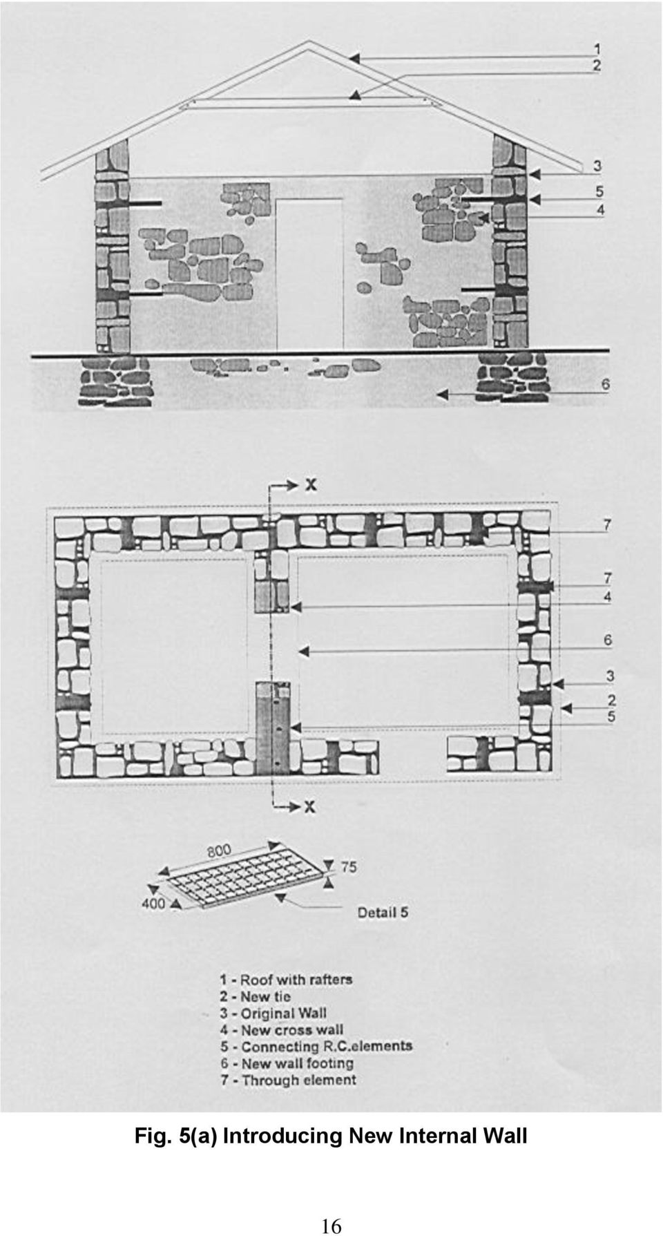
15 0. EARTHQUAKE RESISTANT RETROFITTING OF BUILDINGS For achieving safety of buildings against collapse in a future severe earthquake, the following retrofitting actions are recommanded. The amount and placing of the retrofitting element depends upon the seismic zone, the importance of the building and the stiffness of the base soil. The Categorisation of Buildings is given in Table 3 (See Parts II & III). This Categorisation is in line with IS : where the maximum response in short period range is taken as uniform for all soils. Housing falls under Ordinary buildings. The community buildings are considered under Important buildings. Table 3- Simplified Building Categories in the Seismic Zone D Zone C Zone AB Housing B C D Community Buildings C D E i) Check length, height and thickness of walls and modify to conform to recommendation given in Part II for Rectangular Unit Masonry Buildings and Part III for Stone Masonry Buildings (See Para for ready reference) ii) Check the positions and sizes of openings in masonry walls and modify as required, or provide reinforcement (See Parts II & III) See Para 2 for ready reference). iii) If there are no through stones in thick stone walls, then provide RC headers by making through hole by removing the stones in opposite wythes, inserting an iron link and filling the hole with concrete. iv) Provide seismic belt below roof and above door/window lintel level. For this use weld mesh reinforcement. v) Provide vertical reinforcement at the corners and T-junction of walls, either using bars or ferro-cement with weld-mesh reinforcement. vi) Modify the roof structure by providing additional bracing elements and fix it to the seismic band/belt.. CONTROL ON LENGTH, HEIGHT, THICKNESS OF WALLS a) R.R Stone Masonary. The wall length should not exceed 5m between cross walls in case of mud mortar and 7m in cement mortar case. If length exceeds these, provide internal wall at a spacing not farther than 4m in mud mortar and 5 m in cement mortar case (See Fig. 5). The thickness of new wall should not exceed 400mm. The wall height should not exceed 2.7m in mud mortar and 3.2m in cement mortar (see Table 4). 5

16 Fig. 5(a) Introducing New Internal Wall 6
17 Fig. 5(b) Adding Pilasters/Buttresses to Long Walls 7
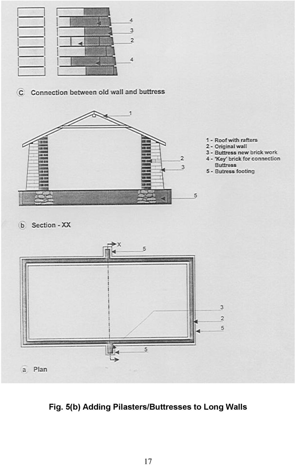
18 b) Rectangular Unit Masonry in cement mortar. The wall length should not exceed 35 t and the height should not exceed 5 t where t = thickness of wall. See Table 4. In case of longer room, external pilasters/battresses may be added as shown in Fig. 5(b) Table 4- Control on Length, Height & Thickness of Walls Type of Masonry Maximum Length of Maximum Height Walls in Room (a) R R Stone Masonry - in Mud Mortar 5 m 2.7 m - in Cement Mortar 7 m 3.2 m of Storey (b) Rectangular Unit Walls 35 t but < 7.0 m 5 t but < 3.5m - in Cement Mortar t = thickness of wall t = thickness of wall 2. CONTROL ON DOOR AND WINDOW OPENINGS IN MASONRY i) Door and window openings should satisfy the following : Distance of jamb from internal corner not less than 450mm and distance between two consecutive openings should be 600mm or more in case of R R masonry and 560mm in rectangular unit masonry both in cement mortar. In case of R R masonry in mud mortar, there should preferably be only one door or window in one wall not exceeding one-third of the wall lenght in the room. The combined length of openings in a wall of rectangular unit masonry building in cement mortar to be restricted to 0.5 L in one storey, 0.42 L in two storey and 0.33 L in three storey building where L is the length of the wall. ii) If the above conditions are not satisfied, action be taken to close an opening or reduce its size. Otherwise, provide strengthening around the opening (Fig.6). For detail of reinforcement, see see Para 6. 8
 Rectangular Unit Walls 35 t but < 7.0 m 5 t but < 3.5m - in Cement Mortar t = thickness of wall t = thickness of wall 2.")
19 Window 2 - Mesh of Ferro-cement 3 - Seismic Belt 4 - Overlap of Mesh Fig. 6 - Reinforcing around opening 3. MAKING THROUGH BOND ELEMENTS IN R.R. STONE WALL (Fig.7) a) Select points where through stones will be installed at horizontal and vertical distance of about one meter apart, with 50cm horizontal stagger. b) Remove the plaster from the surface exposing the stones. Remove the mortar around the stone to sufficient depth gently, not violently, so as to expose the stone on all sides. c) Loosen the stone by means of gentle pushes side ways and up and down by means of a small crowbar, so that the other stones of the walls are not disturbed. Pull out the stone slowly, holding it by both hands. d) Remove inner material gradually so that a 75mm size hole can be made in the wall. Bigger hole is not needed. e) Locate position of the opposite stone on the other face of the wall by gentle tapping in the hole. Remove the identified stone slowly by same gentle process. f) The hole so made through the wall may be bigger in size on both faces and narrower inside resembling a dumbbell shape. This is good. It does not matter if the hole is inclined instead of being horizontal. g) Place concrete of :2:4 mix to fill half the depth of the hole from both sides and place 8mm dia hooked mild steel bar in the hole and fill the hole completely. 9
 Loosen the stone by means of gentle pushes side ways and up and down by means of a small crowbar, so that the other stones of the walls are not disturbed.")
20 a Existing Wall b Making holes c Placing bar and filling concrete Stones removed to make through holes Holes Hooked Bar Chute for pouring concrete Filled concrete Internal wythe External wythe Fig. 7 - Providing R.C. 'through' elements for 'stitching' stone wythes h) Cure for minimum 0 days by sprinkling water on the exposed surfaces on both sides. 4. PROVIDING HORIZONTAL SEISMIC BELTS 4. Seismic Belt Locations i) Seismic belts are to be provided on all walls on both the faces (i) just above lintels of door and window openings and (ii) just below floor or roof. Note : On small wall lengths in a room (less than 5m) seismic band only on the outside face will suffice. In this case these should be connected by ties going across the rooms (see Fig.8). 20
 Seismic belts are to be provided on all walls on both the faces (i) just above lintels of door and window openings and (ii) just below floor or roof.")
21 Seismic belt above openings and below roof at eave level 2 - Seismic belt on gable wall 3 - Tie at eave-band level 4 - Door 5 - Window 6 - Rafter with collar tie 7 - Tying of rafter with band ii) iii) iv) Fig. 8 - Overall arrangement of seismic belts (roofing removed) The belt just below roof or floor may be omitted if the roof or floor is of RCC slab. Seismic belt is not necessary at plinth level, unless the plinth height is more than 900 mm. Install similar seismic belt at the eave level of sloping roof and near top of gable wall, below the roof. Note:- If the height of ceiling/eave level above the top of door in less than 900 mm, only the ceiling/eave level belt may be provided and lintel level belt may be omitted Description of reinforcement in belt. The reinforcement may be of mesh types as suggested in Table 4 or any other mesh of equivalent longitudinal wires. For example in Cat. D building with room length of 6 m, MW 2 weld mesh (with long wires 5 of 4.5 mm dia spaced at 75 mm apart; cross wires of 3.5 mm dia placed at 300 mm apart) can be used, the height of the belt being kept as 375 mm. Note : Weld mesh has to be provided continuously. If splicing is required, there should be minimum overlap of 300mm. 2
22 Table 5- Mesh Reinforcement in Seismic Belts in Various Building Categories. Length of Wall M Cat. B Cat. C Cat. D & E Gauge N H Gauge N H Gauge N H <5.0 g g g g g g g g g bars of 6. Gauge: g3 = 2.34 mm dia of wire. +2bars of 6 g bars of 6 +2 bars of 6 g bars of 6 g bars of 6 2. N = Number of main longitudinal wires in the belt at spacing of 25 mm. Additional longitudinal bars will be 6 mm dia mild steel tied to mesh at 50 mm c/c. 3. H = Height of belt on wall in micro-concrete, mm. 4. The transverse wires in the mesh could be spaced upto 50 mm. 5. The mesh should be galvanized to save from corrosion. 5. VERTICAL SEISMIC BELT AT CORNERS Vertical reinforcing is required at the corners of rooms and junctions of walls as per Table 6. Alternatively MW 2 weld mesh of equivalent longitudinal area could also be used. The width of this belt on each side of the corner has to be kept 25mm extra to the width of the mesh. This reinforcement should be started 300mm below the plinth level and continued into the roof/eave level horizontal band. (See Fig.9). Notes regarding Table 6. Gauge 3 (2.34 mm dia galvanized mesh with 20 mm spacing of wires) shall be used. Additional longitudinal bar will be one T8 mm dia HSD tied to mesh at 50 mm c/c 2. Single bar, if used, shall be HSD or TOR type, if two bars be used in a T-junction, the diameter can be as follws. For One of T0 or T2 take 2 of T8, and for One of T6 take 2 of T2 3. N = Number of longitudinal wires in the mesh, T represents HSD or TOR. 4. B = Width of the micro concrete belt, on each wall meeting at the corner or T-junction. 5. The transverse wires in the mesh could be at a spacing up to 50 mm. 22
23 6. SEISMIC BELTS AROUND DOOR/WINDOW OPENINGS The jambs and piers between window and door openings require vertical reinforcement in the following situations: i) In category D and E buildings for resistance against earthquake forces. ii) For restoring the strength of the piers in any building category when badly damaged in an earthquake. The following mesh reinforcement is recommended to be used for covering the jamb area on both sides of an opening or for covering the pier between the consecutive openings. i) In Cat.D & E buildings Mesh of gauge 0 with 0 wires in vertical direction spaced at 25 mm in a belt width of 280 mm. ii) In Cat. C buildings Mesh of gauge 2 with 9 wires in vertical directon spaced at 25 mm in a belt width of 250 mm. Table 6- Vertical Bar or Mesh Reinforcement in Vertical Belt at Corners of Rooms No. of Storeys Storeys Cat. B Cat. C Cat. D & E Single Bar.mm Mesh Single Bar. mm Mesh Single Bar. mm Mesh N B N B N B One One Two Top Bottom Three Top Middle Bottom
24 t t Masonry wall 2 - Door 3 - Plaster first layer 4 - Steel mesh in belt 5 - Wide head nails 50 long 6 - Plaster second layer 7 - Overlap in steel mesh, 200 mm each side of corner 8 - Vertical seismic belt at junction (going across horizontal belt) 9 - spikes for fixing mesh Fig. 9 - Vertical seismic belts at corner and junction 7. METHOD OF FIXING SEISMIC BELTS The reinforcement specified in Paras 8, 4, 5 and 6 is to be finally attached to the stone wall by nails or connectors and cement mortar. For this purpose either :3 cement-coarse sand mortar or micro-concrete :.5:3 is used. It is applied in two layers like plaster as described below. Steps to construct the Belt Step- Step-2 Step-3 Step-4 Remove plaster in the height of the belt. Rake out mortar joints to 2-5 mm depth. Clean the surface and wet it with water. Apply neat cement slurry and apply first coat of 2 mm thickness. Roughen its surface after initial set. 24
25 Step-5 Step-6 Fix the mesh with 50 mm long nails at about 300 mm apart while plaster is still green. Apply second coat of plaster of 6 mm thickness. Note :. The mesh should be continuous with 200mm overlap at the corner or elsehere. 2. Using galvanized binding wire, tie up the roof rafters with the nails of the eave level belt before applying the plaster over the mesh. 3. In brick and Bela stone walls, it will be easy to drill or chisel out holes of 75 mm dia. In that case, instead of the nails, use 3 mm galvanized mild steel wires through the holes to hold and clamp the longitudinal wires every 450 mm c/c. 8. PROVIDING VERTICAL REINFORCEMENT AT CORNERS, JUNCTIONS OF WALLS The vertical reinforcement consisting of TOR bar as per Table 6 or equivlent shall be provided on the inside corner of room starting from 750 mm below the ground floor going upto the roof slab, passing through each middle floor through holes made in the slabs. (See Fig.0) The reinforcement will be connected to the Wall Perpendicular wall Floor Slab Vertical bar Dowel 6 3 A A A Detail A Fig. 0 - Vertical bar at inside corner 25
26 walls by using L shape dowels of 8 mm TOR bar, the vertical leg of 400 mm length firmly tied to the vertical reinforcement bars and the horizontal leg of minimum 50 mm length embedded in the walls through 75 mm dia. holes drilled in the wall into which the 8 mm dia. leg of the dowel will be grouted using nonhrink cement cum polymer grout. Such dowels will be provided, first one just above plinth level and then at about every m distance apart. The corner reinforcement will be covered with :3 cement mortar or : /2 :3 micro concrete fully bonded with the walls giving a minimum cover of 5 mm on the bar. 9. STIFFENING THE FLAT WOODEN FLOOR/ROOF Many of the damaged houses have flat floor or roof made of wood logs or timber joists covered with wooden planks and earth. For making such roof/floor rigid, long planks 00mm wide and 25 mm thick should be nailed at both ends of the logs/joists from below. Additionally, similar planks or galvanized metal strips.5 mm thick 50 mm wide should be nailed diagonally also. See Fig a Stone building b Brick building Wall Wood joist Wood plank Tie plank under ends of joist Diagonal ties Joint by nailing through 3 mm flat iron Fig. - Stiffening flat wooden floor/roof 26
27 20. STIFFNING THE SLOPING ROOFS STRUCTURE. Most of the sloping roof are usually made of rafters, purlins with covering of burnt clay tiles or corrugated galvanized iron (CGI) sheets or asbestos cement (AC) sheets on top. In Afghanistan sloping roofs on reinforced concrete slabs are also some times used. Such roofs push the walls outward during earthquakes. For stiffening such roofs, the rafters should be tied with the seismic belt as in Note under para 7, and the opposite rafters, on both sides of the ridge need to be connected near about mid-height of the roof through cross ties nailed to the rafters (See Fig. 2). The important point in retrofitting is the provision of seismic belts just below eave level and the gable level. Fig. 2 Stiffening of sloping roof structure 27
28 REFERENCES. Arya, A.S. et. al. (986), Guidelines for Earthquake Resistant Non- Engineered Construction, IAEE Committee, The International Association for Earthquake Engineering, Tokyo. 2. Arya, A.S. (988), Repair and Strengthening of Damaged Stone Houses after Dhamar Earthquake, North Yemen, IX World Conference on Earthquake Engineering, Tokyo-Kyoto, Aug. 2-9, Vol. VIII, pp Arya, A.S. (994), Retrofitting of Stone Houses in Marathwada Area of Maharashtra, Building Materials and Technology Promotion Council (BMTPC), Ministry of Urban Development, Govt.of India. 4. Arya, A.S. (996), Seismic Retrofitting of Stone Houses in Marathwada Area, India, Paper No. 274, XI World Conference on Earthquake Engineering, Acupulco, Maxico. 5. I:S: , Earthquake Resistant Design and Construction of Buildings - Code of Practice, Bureau of Indian Standards, New Delhi. 6. I:S: , Repair and Seismic Strengthening of Building - Guidelines, Bureau of Indian Standards, New Delhi. C:\Afghanistan\guidelines-part4.doc 28
PRESENTATION ON REPAIR AND REHABILITATION OF BUILDINGS DAMAGED IN EARTHQUAKE. By H P Gupta & D K Gupta
 PRESENTATION ON REPAIR AND REHABILITATION OF BUILDINGS DAMAGED IN EARTHQUAKE By H P Gupta & D K Gupta DIFFERENT TYPES OF DAMAGES 1.Minor cracks 0.5 to 5 mm wide in load or non-load bearing walls 2.Major
GSDMA GUIDELINES FOR REPAIR, RESTORATION AND RETROFITTING OF AFFECTED AREAS OF GUJARAT
 GUIDELINES FOR REPAIR, RESTORATION AND RETROFITTING OF MASONRY BUILDINGS IN KACHCHH EARTHQUAKE AFFECTED AREAS OF GUJARAT GSDMA GUJARAT STATE DISASTER MANAGEMENT AUTHORITY GOVERNMENT OF GUJARAT March -
Chapter. Restoration of Damaged Structures
 5 Chapter Restoration of Damaged Structures Bringing back a damaged structure to its pre-earthquake state and original strength is called restoration. This is the first step of building rehabilitation.
Chapter. Earthquake Damage: Types, Process, Categories
 3 Chapter Earthquake Damage: Types, Process, Categories Earthquakes leave behind a trail of damage and destruction. People s lives are affected by the loss of loved ones, destruction of property, economic
After reading this lesson you will be able to: 12.3 IMPORTANCE OF ROOF 12.4 TYPES OF ROOF IN A HOUSE
 86 :: Certificate in Construction Supervision (CIVIL) 12 ROOF 12.1 INTRODUCTION The structure provided to cover the house surface (floor) is known as roof. For different situation and requirement, it is
BILL OF QUANTITY FOR THE WORK OF "REPAIRING OF CIVIL & PLUMBING WORKS INSIDE AND OUTSIDE OF THE WORKSHOP"
 BILL OF QUANTITY FOR THE WORK OF "REPAIRING OF CIVIL & PLUMBING WORKS INSIDE AND OUTSIDE OF THE WORKSHOP" Sl. 1 DISMANTLING WORK 1.1 Stripping off worn out plaster (outside and inside) and raking out joints
REPAIR, RESTORATION AND STRENGTHENING OF BUILDINGS
 Chapter 9 REPAIR, RESTORATION AND STRENGTHENING OF BUILDINGS 9.1 INTRODUCTION The need to improve the ability of an existing building to withstand seismic forces arises usually from the evidence of damage
Strong earthquakes in seismic regions are inevitable! Build your house safely to avoid future disaster!
 Central Asia Earthquake Safety Initiative SEISMIC SAFETY FOR ADOBE HOMES: what everyone should know Seismic Damage to Adobe Homes Central Asia is known for periodic large earthquakes. Strong earthquakes
STRUCTURAL CONCEPT FOR LIGHT GAUGE STEEL FRAME SYSTEM
 Chapter 9 STRUCTURAL CONCEPT FOR LIGHT GAUGE STEEL FRAME SYSTEM 9.1 BACKGROUND Steel is widely used in the construction of multi-storey buildings. However, steel construction is seldom used and is traditionally
How To Repair A House After An Earthquake
 REHABILITATION Anti-seismic construction handbook Arch. Wilfredo Carazas Aedo Arch. Alba Rivero Olmos CRATerre-EAG PRELUDE Earthquakes have a considerable effect on adobe houses built with a large number
Disclosure to Promote the Right To Information
 इ टरन ट म नक Disclosure to Promote the Right To Information Whereas the Parliament of India has set out to provide a practical regime of right to information for citizens to secure access to information
STRUCTURAL VULNERABILITY REDUCTION
 STRUCTURAL VULNERABILITY REDUCTION Content 1. Background 2. Implementation Strategy for Achieving Seismic Safety 3. Analysis of Existing Construction Mechanism 3.1 Type of building construction mechanism
201 WATER STREET FORWARDERS MUSEUM AND VISITORS INFORMATION CENTRE
 STRUCTURAL INSPECTION REPORT DRAFT 201 WATER STREET FORWARDERS MUSEUM AND VISITORS INFORMATION CENTRE TOWN OF PRESCOTT Date: November 2013 GENIVAR No.: 131-20617-00 2611 Queensview Drive, Suite 300, Ottawa,
Detailing of Reinforcment in Concrete Structures
 Chapter 8 Detailing of Reinforcment in Concrete Structures 8.1 Scope Provisions of Sec. 8.1 and 8.2 of Chapter 8 shall apply for detailing of reinforcement in reinforced concrete members, in general. For
Foundation Experts, LLC Specializes in Foundation Repair and Waterproofing
 1 Most basements show some signs of leaking and cracking. Through the years, problems with water, poor soils, grading, drainage and possible settling affect the integrity of a basement. Being able to recognize
HOUSE BUILDING DIGEST
 HOUSE BUILDING DIGEST (Construction Specifications-Foundations) Creating Enabling Environment for Affordable Housing for All This is an attempt by BMTPC to provide useful but often ignored information
EAST LYME HIGH SCHOOL
 Overview: 1971 N 1966 GYM 1966 CLASSROOM WING 1966 AUD. 1971 GYM 1998 1998 POOL EAST LYME HIGH SCHOOL Original 1966 Building: The original East Lyme High School was constructed in 1966 and was composed
Foundations 65 5 FOUNDATIONS. by Richard Chylinski, FAIA and Timothy P. McCormick, P.E. Seismic Retrofit Training
 Foundations 65 5 FOUNDATIONS by Richard Chylinski, FAIA and Timothy P. McCormick, P.E. 66 Foundations Foundations 67 FOUNDATIONS Let's assume that the retrofit has been done correctly from the roofline
DISASTER RESISTANCE EARTHQUAKES AND STRUCTURES
 DISASTER RESISTANCE EARTHQUAKES AND STRUCTURES EARTHQUAKES Origin of earthquakes The earth was a single land about two hundred million years ago. This land split progressively over a long period of time
COST-EFFECTIVE RETROFITTING MEASURES FOR KASHMIR VALLEY
 ISET GOLDEN JUBILEE SYMPOSIUM Indian Society of Earthquake Technology Department of Earthquake Engineering Building IIT Roorkee, Roorkee October 20-21, 2012 Paper No. E002 COST-EFFECTIVE RETROFITTING MEASURES
Structural Failures Cost Lives and Time
 Structural Failures Cost Lives and Time Recent failures of storage bins, silos and other structures highlight the need to increase awareness of hazards associated with these structures. Since 2010, one
6 RETROFITTING POST & PIER HOUSES
 Retrofitting Post & Pier Houses 71 6 RETROFITTING POST & PIER HOUSES by James E. Russell, P.E. 72 Retrofitting Post & Pier Houses Retrofitting Post & Pier Houses 73 RETROFITTING POST AND PIER HOUSES This
Chapter 3 Pre-Installation, Foundations and Piers
 Chapter 3 Pre-Installation, Foundations and Piers 3-1 Pre-Installation Establishes the minimum requirements for the siting, design, materials, access, and installation of manufactured dwellings, accessory
MILMAN & ASSOCIATES STRUCTURAL CONSULTING ENGINEERS/ PROJECT MANAGERS
 MILMAN & ASSOCIATES STRUCTURAL CONSULTING ENGINEERS/ PROJECT MANAGERS May 29, 2013 Revision B Structural Guideline for Design and Installation Holes in Composite Floor Slab Terminal 3, Departure Level
Seismic Retrofitting and Repair Manual for Buildings
 U N D P Pakistan Seismic Retrofitting and Repair Manual for Buildings Earthquake Vulnerability Reduction Project (EVRP) & TECHN O P ENGINEE R GY LO OF G IN IVERSIT UN Y December 2009 NW F Seismic Retrofitting
Retrofitting of Existing RCC Buildings by Method of Jacketing
 Retrofitting of Existing RCC Buildings by Method of Jacketing BHAVAR DADASAHEB O. Assistant Professor, Sandip Institute of Engineering & Managemnt, At Post Mahiravani, Trimbak Road, Nashik. Maharashtra
PLUMBING MAINTENANCE WORK FOR TOILETS IN HEAD OFFICE, SUPPLYCO ESTIMATE
 Sl.No. PLUMBING MAINTENANCE WORK FOR TOILETS IN HEAD OFFICE, SUPPLYCO ESTIMATE Description of item Qty Unit Rate Amount 1 Demolishing tile work/cement concrete/( carefully taking out the closet and other
City of Tucson and Pima County Arizona Building Code Appendix Chapter 72 Straw-Bale Structures
 City of Tucson and Pima County Arizona Building Code Appendix Chapter 72 Straw-Bale Structures SECTION 7201 - PURPOSE The purpose of this appendix chapter is to establish minimum prescriptive standards
Chapter 36 - STRAW BALE CONSTRUCTION SECTION 3601 - PURPOSE. SECTION 3602 - SCOPE. SECTION 3603 - DEFINITIONS.
 Austin City Code - Volume II TITLE 25 LAND DEVELOPMENT\CHAPTER 25-12 TECHNICAL CODES\ARTICLE 1: UNIFORM BUILDING CODE\25-12-3 LOCAL AMENDMENTS TO THE BUILDING CODE Chapter 36 - STRAW BALE CONSTRUCTION
CHAPTER NO. 27 QUANTITIES OF MATERIALS
 CHAPTER NO. 27 QUANTITIES OF MATERIALS Note :- One cement bag weighs 50 kg. and measures 0.03472 cum. Sr. No. Description Unit Quantities Fine aggregates Coarse aggregates 1 2 3 4 5 6 27.1 Cement concrete
POST AND FRAME STRUCTURES (Pole Barns)
") POST AND FRAME STRUCTURES (Pole Barns) Post and frame structures. The following requirements serve as minimum standards for post and frame structures within all of the following structural limitations:
POST AND FRAME STRUCTURES (Pole Barns) Post and frame structures. The following requirements serve as minimum standards for post and frame structures within all of the following structural limitations:
TECHNICAL SPECIFICATION SERIES 8000 PRECAST CONCRETE
 TECHNICAL SPECIFICATION SERIES 8000 PRECAST CONCRETE TECHNICAL SPECIFICATION PART 8000 - PRECAST CONCRETE TABLE OF CONTENTS Item Number Page 8100 PRECAST CONCRETE CONSTRUCTION - GENERAL 8-3 8101 General
LAYING BLOCK AND BRICK
 LAYING BLOCK AND BRICK Products highlighted in this section: SAKRETE Type N Mortar Mix SAKRETE Type S Mortar Mix Brick And Block Laying Basics The first step in building a brick or block wall is to construct
Guide to Safe Building Practices
 Guide to Safe Building Practices Guide to Safe Building Practices This is a guide for tradesmen, builders and contractors to help them build, repair and retrofit buildings and particularly roofs, with
SEISMIC ANALYSIS AND RETROFITTING OF R.C.C STRUCTURE
 International Journal of Advanced Research in Biology Engineering Science and Technology (IJARBEST) Vol., Issue, April 1 SEISMIC ANALYSIS AND RETROFITTING OF R.C.C STRUCTURE M.R.NAVANEETHA KRISHNAN 1,
Residential Deck Safety, Construction, and Repair
 Juneau Permit Center, 4 th Floor Marine View Center, (907)586-0770 This handout is designed to help you build your deck to comply with the 2006 International Residential Building code as modified by the
How To Repair A House
 Assessing Structural Damages Please note-this presentation is only intended to be used as a basic educational tool and is by no means all encompassing. Each property should be treated on a case by case
September 1, 2003 CONCRETE MANUAL 5-694.900 CONCRETE PAVEMENT REHABILITATION 5-694.900
 September 1, 2003 CONCRETE MANUAL 5-694.900 5-694.901 GENERAL CONCRETE PAVEMENT REHABILITATION 5-694.900 Concrete Pavement Rehabilitation is an extremely valuable tool of the Minnesota Department of Transportation
TRAINING OUTLINE FOR PART TIME BUILDERS
 TRAINING OUTLINE FOR PART TIME BUILDERS This is a training outline for persons who get involved in repair work and minor building work, emphasizing disaster resistance and good practice. It is intended
EARTHQUAKE DESIGN OF BUILDINGS
 GAP.2.0.9 A Publication of Global Asset Protection Services LLC EARTHQUAKE DESIGN OF BUILDINGS INTRODUCTION Buildings in many areas of the world are susceptible to damage from moderate to severe earthquakes.
Repair and Rehabilitation of Nehru Memorial College of K.V.G. Group of Institutions at Mangalore - A Case Study
 Repair and Rehabilitation of Nehru Memorial College of K.V.G. Group of Institutions at Mangalore - A Case Study Surresh Chandra Pattanaik ab, E. Gopal Krishnan b and Mohan Kumar c a School of Civil Engineering,
RESIDENTIAL MASONRY A BEST PRACTICES GUIDE
 RESIDENTIAL MASONRY A BEST PRACTICES GUIDE Build With Brick Build With Boral CONTENTS BRICK :01 MASONRY CEMENT :03 MASONRY SAND :04 WALL TIES :05 STEEL LINTELS :07 DRAINAGE WALL SYSTEM :09 FLASHING :11
Technical Notes 3B - Brick Masonry Section Properties May 1993
 Technical Notes 3B - Brick Masonry Section Properties May 1993 Abstract: This Technical Notes is a design aid for the Building Code Requirements for Masonry Structures (ACI 530/ASCE 5/TMS 402-92) and Specifications
Mark Cramer Inspection Services, Inc.
 Mark Cramer Inspection Services, Inc. 492 Twentieth Avenue, Indian Rocks Beach, FL 34635-2970 (727) 595-4211 Fax (727) 596-7583 Certified Member #12085 American Society of Home Inspectors Construction
STRUCTURAL ASSESSMENT REPORT BOLINAS MARINE STATION - BOLINAS, CALIFORNIA
 STRUCTURAL ASSESSMENT REPORT BOLINAS MARINE STATION - BOLINAS, CALIFORNIA College of Marin c/o Swinerton Management & Consulting P.O. Box 144003 835 College Avenue, Building MS-3 Kentfield, California
RESIDENTIAL ROOFING & RE-ROOFING, ROOF VENTILATION AND ROOF SHEATHING REQUIREMENTS MICHIGAN RESIDENTIAL CODE 2000
 RESIDENTIAL ROOFING & RE-ROOFING, ROOF VENTILATION AND ROOF SHEATHING REQUIREMENTS MICHIGAN RESIDENTIAL CODE 2000 SECTION R905 REQUIREMENTS FOR ROOF COVERINGS R905.1 Roof covering application. Roof coverings
Elevating Your House. Introduction CHAPTER 5
 CHAPTER 5 Elevating Your House Introduction One of the most common retrofitting methods is elevating a house to a required or desired Flood Protection Elevation (FPE). When a house is properly elevated,
Residential Foundations and Basements
 Residential Foundations and Basements Disclaimer All of the following information is based on the 2006 International Residential Code with Kentucky Amendments. As some information is paraphrased, article
Strengthening of Brick Masonry Walls against Earthquake Loading
 International Journal of Advanced Structures and Geotechnical Engineering ISSN 2319-5347, Vol. 01, No. 01, July 2012 Strengthening of Brick Masonry Walls against Earthquake ing KHAN SHAHZADA, MUHAMMAD
Chapter 6 ROOF-CEILING SYSTEMS
 Chapter 6 ROOF-CEILING SYSTEMS Woodframe roof-ceiling systems are the focus of this chapter. Cold-formed steel framing for a roof-ceiling system also is permitted by the IRC but will not be discussed;
NCMA TEK CONCRETE MASONRY FOUNDATION WALL DETAILS. TEK 5-3A Details (2003)
") NCMA TEK National Concrete Masonry Association an information series from the national authority on concrete masonry technology CONCRETE MASONRY FOUNDATION WALL DETAILS TEK 5-3A Details (2003) Keywords:
NCMA TEK National Concrete Masonry Association an information series from the national authority on concrete masonry technology CONCRETE MASONRY FOUNDATION WALL DETAILS TEK 5-3A Details (2003) Keywords:
SECTION 7 Engineered Buildings Field Investigation
 SECTION 7 Engineered Buildings Field Investigation Types of Data to Be Collected and Recorded A field investigator looking at engineered buildings is expected to assess the type of damage to buildings.
PROJECT TITLE : 2-STOREY RESIDENCE LOCATION : ALONG DAANG HARI,MOLINO.BACOOR,CAVITE OWNER : CUEVASVILLE REALTY
 PROJECT TITLE : 2-STOREY RESIDENCE LOCATION : ALONG DAANG HARI,MOLINO.BACOOR,CAVITE OWNER : CUEVASVILLE REALTY GENERAL SPECIFICATIONS These specifications are intended to cover the construction of the
1997 Uniform Administrative Code Amendment for Earthen Material and Straw Bale Structures Tucson/Pima County, Arizona
 for Earthen Material and Straw Bale Structures SECTION 70 - GENERAL "APPENDIX CHAPTER 7 - EARTHEN MATERIAL STRUCTURES 70. Purpose. The purpose of this chapter is to establish minimum standards of safety
DESIGN OF SLABS. 3) Based on support or boundary condition: Simply supported, Cantilever slab,
 Based on support or boundary condition: Simply supported, Cantilever slab,") DESIGN OF SLABS Dr. G. P. Chandradhara Professor of Civil Engineering S. J. College of Engineering Mysore 1. GENERAL A slab is a flat two dimensional planar structural element having thickness small compared
DESIGN OF SLABS Dr. G. P. Chandradhara Professor of Civil Engineering S. J. College of Engineering Mysore 1. GENERAL A slab is a flat two dimensional planar structural element having thickness small compared
Page & Turnbull imagining change in historic environments through design, research, and technology
 DCI+SDE STRUCTURAL EVALUATIONS OFFICE BUILDING, TOOL SHED & WATER TANK, AND BLACKSMITH & MACHINE SHOP BUILDINGS SAN FRANCISCO, CALIFORNIA [14290] PRIMARY PROJECT CONTACT: H. Ruth Todd, FAIA, AICP, LEED
HURRICANE MITIGATION RETROFITS FOR EXISTING SITE-BUILT SINGLE FAMILY RESIDENTIAL STRUCTURES
 HURRICANE MITIGATION RETROFITS FOR EXISTING SITE-BUILT SINGLE FAMILY RESIDENTIAL STRUCTURES 101 Retrofits Required. Pursuant to Section 553.844 553.884, Florida Statutes, strengthening of existing site-built,
The better way to build TM. Installation Manual. FOUNDATION SIPs & FROST WALLS SIPs
 The better way to build TM Installation Manual FOUNDATION SIPs & FROST WALLS SIPs February 2016 PWF FOUNDATION & FROST WALL SIPs Installation Manual Table of Contents Topics General Requirements...................................
Miss S. S. Nibhorkar 1 1 M. E (Structure) Scholar,
 Scholar,") Volume, Special Issue, ICSTSD Behaviour of Steel Bracing as a Global Retrofitting Technique Miss S. S. Nibhorkar M. E (Structure) Scholar, Civil Engineering Department, G. H. Raisoni College of Engineering
Volume, Special Issue, ICSTSD Behaviour of Steel Bracing as a Global Retrofitting Technique Miss S. S. Nibhorkar M. E (Structure) Scholar, Civil Engineering Department, G. H. Raisoni College of Engineering
Rehabilitation of Existing Foundation Building to Resist Lateral and Vertical Loads
 International Journal of Current Microbiology and Applied Sciences ISSN: 2319-7706 Volume 3 Number 12 (2014) pp. 950-961 http://www.ijcmas.com Original Research Article Rehabilitation of Existing Foundation
Guidelines for Earthquake Bracing of Residential Water Heaters
 Guidelines for Earthquake Bracing of Residential Water Heaters Department of General Services Division of the State Architect 1102 Q Street, Suite 5100 Sacramento, CA 95814 Phone: (916) 324-7099 Fax: (916)
ICRC WORK SPECIFICATIONS IRAQ WATER AND HABITAT
 ICRC WORK SPECIFICATIONS IRAQ WATER AND HABITAT GOVERNORATE : DISTRICT : LOCATION : DOHUK SUMEL SUMEL GO code : IRAK GEN ASSENG0 TITLE : Sharia / PHCC / Rehabilitation SO n : SO 03 WPA n : KIR16 0015 Job
Superform Products Ltd.
 TYPICAL CORNER REINFORCING NOTE : SEE ENGINEERED REBAR SCHEDULES SUPPLIED BY THE MANUFACTURER STEEL REINFORCEMENT WALL CORNER 90 Copyright 2012 Sept. 2012 5.1.1 Rebar Spacing 6" 12" Max. Load LB./FT. 2000
Design and Construction of Cantilevered Reinforced Concrete Structures
 Buildings Department Practice Note for Authorized Persons, Registered Structural Engineers and Registered Geotechnical Engineers APP-68 Design and Construction of Cantilevered Reinforced Concrete Structures
PC-Concrete Injectable Concrete Anchoring and Repair System
 PC-Concrete Injectable Concrete Anchoring and Repair System DESCRIPTION: PC-Concrete is a two component (1:1 ratio), 100% solids, high modulus, structural epoxy paste. PC-Concrete is a solvent free, no
How to build a Pizza Oven in 4 days
 How to build a Pizza Oven in 4 days Preparation day (slab) 1. Foundation 1500 deep x 1300 wide x 75mm deep Required 20 bags cement pre mix. If you already have a concrete base, you save this prep day DAY
CHAPTER 2 QUANTITY TAKE-OFF
 CHAPTER 2 QUANTITY TAKEOFF The quantity takeoff is an important part of the cost estimate. It must be as accurate as possible and should be based on all available engineering and design data. Use of appropriate
7. Installation. installation 7.1.1. CAST-IN WINDOW SYSTEM 7.1. INSTALLATION OF WINDOW MAIN FRAME
 7. Installation Window involves the fixing of window frame at an earlier construction stage and subsequent of the window sashes. This is a highly workmanship dependent process. Only trained and approved
in the construction. Others identify the options and the design that will result in to lowest
 Retrofitting Going Green by Reducing Reconstruction Green options are discussed when one is planning to construct a new building. Some try to identify the viable option having lowest energy input in the
INSTALLATION. General. Important Note. Design. Transport
 General The roof trusses you are about to install have been manufactured to precise engineering standards. To ensure that the trusses perform as designed, it is essential that they be handled, erected
FORM DESIGN. easy to work with, and generally available.
 Forms play a major role in concrete construction. They give the plastic concrete its shape and hold it until it hardens. Forms protect the concrete, assist in curing it, and support any reinforcing rods
BUILDING WITH STONE AND EARTH
 BUILDING WITH STONE AND EARTH PART 1 Earth is a popular building material all over the world. It can be used by itself, but if there is stone available, then the two can be used together to make very good
COMMONLY USED RESIDENTIAL BUILDING CODES
 COMMONLY USED RESIDENTIAL BUILDING CODES INTERNATIONAL RESIDENTIAL CODE (2009) form revised 5/10 FOUNDATION 1. DESIGN OF FORMWORK. Section 1906.1 IBC 2009, Section R404.1.2.3.6 IRC 2009, ACI 318 Section
SECTION 15076 CEMENT-MORTAR LINED AND COATED STEEL PIPE
 SECTION 15076 CEMENT-MORTAR LINED AND COATED (CML&C) STEEL PIPE PART 1 GENERAL 1.01 DESCRIPTION This section designates the requirements for steel pipe fabrication, test in shop, installation of steel
CARPENTRY - HOUSING. This is the sloping length of a right-angled triangle.
 CARPENTRY - HOUSING PART 2: GABLE ROOFS The gable roof is classified as being double-pitched and one of the simplest roof forms, due to the fact that all rafters in the roof are exactly the same length
If stepping is required, step at 180mm as seen in this picture.
 Cast Foundations to standard building regulations requirements. Foundations must be cast completely level, 600mm wide by 230mm deep for single storey, double storey is not allowed by NHBRC. If stepping
SECTION 02630 STORM DRAINAGE SYSTEM
 SECTION 02630 PART 1 - GENERAL 1.01 DESCRIPTION A. Section includes specifications for storm drainage systems including modifications and connections to existing storm drainage systems. 1.02 REFERENCE
Comparison of Seismic Retrofitting Methods for Existing Foundations in Seismological Active Regions
 Comparison of Seismic Retrofitting Methods for Existing Foundations in Seismological Active Regions Peyman Amini Motlagh, Ali Pak Abstract Seismic retrofitting of important structures is essential in seismological
BILL OF QUANTITIES FOR CIVIL WORKS FOR 8MW POWER PLANT
 BILL OF QUANTITIES FOR CIVIL WORKS FOR 8MW POWER PLANT ITEM Description Unit Quantity (approx) [A] A-1 EARTH WORK Earthwork in excavation in all types of soil/rock but excluding hard rock requiring blasting
How To Build A Gambrel Roof And A Gable End Roof
 Dutch Gable or Gambrel Roof and The Scotch Valley The folowing pages are an extract from Carp 12 text TAFE NSW Construction and Transport Division 71 HIP and VALLEY ROOFING GAMBREL / DUTCH GABLE The effect
Expected Performance Rating System
 Expected Performance Rating System In researching seismic rating systems to determine how to best classify the facilities within the Portland Public School system, we searched out what was used by other
March 14, 2007. Installation of Bay, Bow and Garden Windows
 March 14, 2007 Re: Installation of Bay, Bow and Garden Windows Attached are the Atrium Companies, Inc recommendation for the installation of bay, bow and garden windows. These instructions were developed
June 2007 CHAPTER 7 - CULVERTS 7.0 CHAPTER 7 - CULVERTS 7.1 GENERAL
 7.0 7.1 GENERAL For the purpose of this manual, culverts are defined as structures that are completely surrounded by soil and located below the surface of the roadway parallel to the general direction
Basement & Foundation Damage
 Basement & Foundation Damage Please note-this presentation is only intended to be used as a basic educational tool and is by no means all encompassing. Each property should be treated on a case by case
3. Observed Damage in Railway Viaducts
 Structural Damage of Tohoku Shinkansen Viaducts by the Off the Pacific Tohoku Earthquake First Report on March 16, 2011 Dr. Yoshikazu Takahashi, Associate Professor Disaster Prevention Research Institute,
Minor Cracks in Horizontal Surfaces
 Cracks, chips and broken or flaking areas in concrete are not only unsightly, they can lead to further deterioration of the surface. The result is a costly replacement project as opposed to a simple repair.
STRUCTURAL ASSESSMENT. Full Metal Jacket Building 0 Prince Street, Alexandria, VA
 STRUCTURAL ASSESSMENT FOR Full Metal Jacket Building 0 Prince Street, Prepared by: ALPHA CORPORATION (Alpha) 1850 S. Loudoun Street, Suite 200 Winchester, VA 22601 540-723-0704 September 22, 2010 J. Michael
symptoms of a faulty foundation
 symptoms of a faulty foundation How does drought impact your home's foundation? For many Texas families, their home becomes the single largest investment and also the family fortune. The home's foundation
Guidelines for Earthquake Bracing Residential Water Heaters
 Guidelines for Earthquake Bracing Residential Water Heaters Department of General Services Division of the State Architect In accordance with the Health and Safety Code Section 19215, the Division of the
Attachment G-1: Pit Latrine Diagram. Fig E.1a: Pit Latrine. Fig E.1b: Plan View of Twin Pits
 Attachment G-1: Pit Latrine Diagram Fig E.1a: Pit Latrine Fig E.1b: Plan View of Twin Pits Fig E.1c: Section of a water-sealed pan Fig E.1d: 3D view of Overflow Pipe Fig E.1e: 2D view of Overflow Pipe
HOUSING RECONSTRUCTION AND RETROFITTING AFTER THE 2001 KACHCHH, GUJARAT EARTHQUAKE
 13 th World Conference on Earthquake Engineering Vancouver, B.C., Canada August 1-6, 2004 Paper No. 1723 HOUSING RECONSTRUCTION AND RETROFITTING AFTER THE 2001 KACHCHH, GUJARAT EARTHQUAKE Elizabeth A.
Engineers, Civil Structural Survey
 Engineers, Civil Structural Survey 317 STREET 0 6 3 6 0 886-1966 886-9165 FAX. September 1 1 Mr. Alan Bergren City Manager City of Norwich Broadway, Floor Norwich, 06360 Re: Limited Structural Condition
Module 3.7. Thermal bridging
 Module 3.7 Thermal bridging Learning Outcomes On successful completion of this module learners will be able to - Describe construction details which influence thermal bridging. 2 Introduction to thermal
How to secure your property after a disaster
 How to secure your property after a disaster The Red Guide to Recovery HOuse secured properly Board-Up of Windows, Doors and Roof Hole. Lot secured with Perimeter Fencing. Fires, floods, tornadoes, hurricanes,
Siting and settlement: The most important way to protect shelter from floods is to build in a place that is unlikely to be flooded.
 Siting and settlement: The most important way to protect shelter from floods is to build in a place that is unlikely to be flooded. Key Messages Shelters and settlements should be sited above the highest
Chapter 3 DESIGN AND CONSTRUCTION FEATURES IMPORTANT TO SEISMIC PERFORMANCE
 Chapter 3 DESIGN AND CONSTRUCTION FEATURES IMPORTANT TO SEISMIC PERFORMANCE To satisfy the performance goals of the NEHRP Recommended Seismic Provisions, a number of characteristics are important to the
ASSESSMENT AND RETROFITTING OF EXISTING RC BUILDINGS IN VIETNAM IN TERMS OF EARTHQUAKE RESISTANCES
 GEM-SEA Workshop on Seismic Vulnerability of Buildings Nanyang Technological University, Singapore 1 st July 2013 ASSESSMENT AND RETROFITTING OF EXISTING RC BUILDINGS IN VIETNAM IN TERMS OF EARTHQUAKE
CONCRETE FLOOR SLAB & CASTING BED CONSTRUCTION
 CONCRETE FLOOR SLAB & CASTING BED CONSTRUCTION General 7 www.meadowburke.com 877-518-7665 MB1109 CONCRETE FLOOR SLAB AND CASTING BED CONSTRUCTION Quality Construction Begins at Ground Level Everything
Project Report. Structural Investigations Hotel del Sol Yuma, Arizona
 Project Report Structural Investigations Yuma, Arizona Prepared by: 2619 Spruce Street Boulder, CO 80302 303-444-3620 Prepared for: Principle Engineering Group, Inc. 833 East Plaza Circle, Suite 100 Yuma,
Asphalt Shingle Application Requirements
 Alberta Allied Roofing Association Asphalt Shingle Application Requirements Section 1 Roof Decks 1.1 General Asphalt Shingles are not permitted to be installed directly over rigid insulation. When Asphalt