SETTLEMENT INSTRUMENTATION & MONITORING
|
|
|
- Annabel Bates
- 8 years ago
- Views:
Transcription
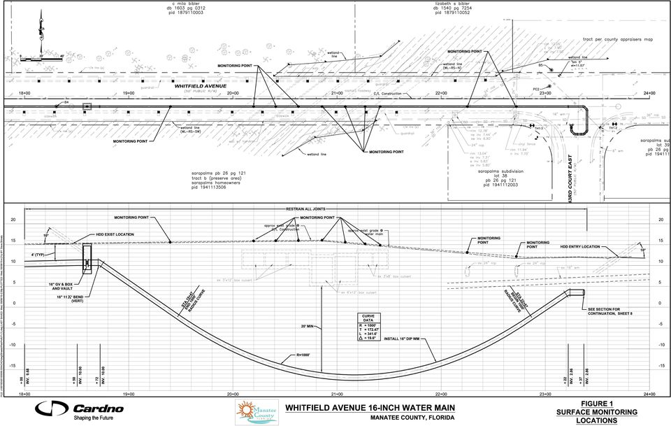
1 SECTION SETTLEMENT INSTRUMENTATION & MONITORING PART 1 - GENERAL 1.01 SUMMARY A. The Work specified in this Section includes furnishing, installing, and monitoring settlement instrumentation to monitor ground movements around and above HDD operations. The work includes, but is not limited to: installing surface monitoring points shown in Figure 1, furnishing monitoring equipment, and recording observations and measurements from the monitoring points on a periodic basis before, during, and after HDD operations. B. The Contractor is responsible for surveying the elevations of the surface monitoring points in accordance with the requirements herein. Elevations shall be determined before HDD operations begin to establish a baseline. Survey readings shall continue during and after HDD operations to monitor any movements related to the HDD construction. All monitoring points shall be surveyed one week and one month after all HDD has been completed to evaluate long-term settlements RELATED WORK SPECIFIED ELSEWHERE A. Section Horizontal Directional Drilling B. Section Annular Space and Contract Grouting 1.03 DEFINITIONS A. Surface Control Points: Control points established as a reference for measuring elevation of the ground surface using optical survey methods QUALITY ASSURANCE A. Surveyor Qualifications: Surveying for monitoring control points shall be performed by a land surveyor licensed in the State of Florida with previous experience surveying for the detection of structural or surface deformations. B. Install surface control points within one-half (0.5) foot of the horizontal and vertical location shown on the Drawings or as directed by the Engineer. C. Should actual field conditions prevent installation of instruments at the locations shown on the Drawings or specified herein, Contractor shall obtain written acceptance from the Engineer for new instrument location and elevation SUBMITTALS A. Submittals shall be made in accordance with Special Provisions of the contract documents. Provide sufficient detail to allow the Engineer to judge whether the proposed equipment, materials, and procedures will meet the Contract requirements. All drawings shall be legible with dimensions accurately shown and clearly marked in English. Drawings and photographs transmitted by a facsimile will not be accepted. The Engineer s Settlement Instrumentation.docx 1 / 10 05/08/2015

2 review of submitted details and data will be based on consideration of requirements for the completed work, protection of utilities and surface features, and the possibility of unnecessary delays in the execution of the work to be constructed under this Contract. Review and acceptance of the Contractor s submittals by the Engineer shall not be construed in any way as relieving the Contractor of its responsibilities under this Contract. 1. Qualifications: Submit surveying personnel qualifications in accordance with Paragraph 1.05 A. 2. Submit the following, at least one (1) month before scheduled installation of monitoring points: a. Instrumentation Schedule: Submit the proposed schedule for installing the surface monitoring points. b. Description of methods and materials for installing surface monitoring points. c. If Contractor proposes to install any instruments at locations other than those shown on the Drawings, submit drawings with alternate locations of proposed monitoring points shown in plan and profile. 3. Reports and Records: a. Provide reports of monitoring control point data to the Engineer by noon of the day following the shift for which the measurements were taken. b. Within 72 hours following installation of the instruments, submit drawings showing the actual as-built location, the instrument identification number, the instrument type, the installation date and time, and the tip elevation and instrument length. Include details of installed instruments, accessories and protective measures including all dimensions and materials used. c. Submit surveyed measurements of all monitoring points at least seven (7) days prior to commencing construction of shafts to establish baseline readings. d. Submit surveyed measurements of monitoring points during and after construction in accordance with Paragraph 3.01 C. PART 2 - PRODUCTS 2.01 MATERIALS A. Surface Control Points: Surface control points shall be established by an inscribed marking or approved surveyor s nail driven flush with the surface in asphalt or concrete paved areas. In landscaped areas, surface control points shall be established by driving a 2-inch by 2-inch by 18-inch long timber stake flush with the ground. Each control point shall have a tag or marking indicating the station and offset from centerline. PART 3 - EXECUTION 3.01 GENERAL REQUIREMENTS Settlement Instrumentation.docx 2 / 10 05/08/2015
 month before scheduled installation of monitoring points: a.")
3 A. Instrumentation shall be installed at the locations shown on the Drawings, or as directed by the Engineer. Instruments shall be installed in accordance with the approved installation schedule. B. Contractor shall install and perform a baseline survey of all surface settlement monitoring devices at least seven (7) days prior to the commencement of HDD operations. C. Once HDD operation commences, settlement points shall be surveyed once for every 10 feet of installed pipe. Additionally, all settlement monitoring devices shall be surveyed once per day for a period of one week, once at 14 days, and once at 30 days, after HDD operation is complete. D. Contractor shall provide access and assistance to the Engineer for obtaining supplemental monitoring data, as requested by Engineer SURFACE CONTROL POINTS A. Establish system of ten (10) surface control points and monitor in accordance with the appropriate Sections noted in Paragraph 1.02 and with the requirements herein. B. Surface control points shall be monitored by the Contractor in accordance with the appropriate Sections noted in Paragraph 1.02 and with the requirements herein. C. Provide data from readings of surface control points to the Engineer within 24 hours of reading INSTRUMENT PROTECTION, MAINTENANCE, AND REPAIR A. Protect the instruments and control points from damage. Damaged installations shall be replaced or repaired prior to continuing the HDD operation, unless permitted otherwise in writing by the Engineer ABANDONMENT OF INSTRUMENTS A. Surface Control Points: All surface control points on public property shall remain in place at the completion of the Work. Remove all surface control points on private property during the cleanup and restoration work, or as required by the Engineer Settlement Instrumentation.docx 3 / 10 05/08/2015

4
5 Contractor: Measured by: Date and Time Boring position (feet from shaft) Surface Settlement Pt. 1 Surface Settlement Pt. 2 Surface Settlement Pt. 3 Settlement/ Baseline Note: Settlement measurements to be surveyed at least once daily Settlement Instrumentation.docx 5 / 10 05/08/2015

6 Legend x Settlement Point Settlement Point 2 Settlement Point Distance from shaft to Boring face (feet) Settlement Instrumentation.docx 6 / 10 05/08/2015
 02445 Settlement")
7 Contractor: Measured by: Date and Time Boring position (feet from shaft) Surface Settlement Pt. 4 Surface Settlement Pt. 5 Surface Settlement Pt. 6 Settlement/ Baseline Note: Settlement measurements to be surveyed at least once daily Settlement Instrumentation.docx 7 / 10 05/08/2015

8 1.5 Legend x Settlement Point Settlement Point 5 Settlement Point Distance from shaft to bore face (feet) Settlement Instrumentation.docx 8 / 10 05/08/2015
 02445 Settlement")
9 Contractor: Measured by: Date and Time Boring position (feet from shaft) Surface Settlement Pt. 7 Surface Settlement Pt. 8 Surface Settlement Pt. 9 Surface Settlement Pt. 10 Settlement/ Settlement/ Baseline Note: Settlement measurements to be surveyed at least once daily Settlement Instrumentation.docx 9 / 10 05/08/2015

10 Legend x Settlement Point Settlement Point 8 Settlement Point o Settlement Point Distance from shaft to Boring face (feet) END OF SECTION Settlement Instrumentation.docx 10 / 10 05/08/2015

High Strain Dynamic Load Testing of Drilled Shafts
 Supplemental Technical Specification for High Strain Dynamic Load Testing of Drilled Shafts SCDOT Designation: SC-M-712 (9/15) September 3, 2015 1.0 GENERAL This work shall consist of performing high-strain
SECTION 02200 SUPPORT OF EXCAVATION
 SECTION 02200 PART 1 GENERAL 1.01 DESCRIPTION A. Section including specifications for design and installation of excavation support. B. Section also includes specifications for excavation support systems
SUPPLEMENTAL TECHNICAL SPECIFICATIONS BI-DIRECTIONAL STATIC LOAD TESTING OF DRILLED SHAFTS
 July 14, 2015 1.0 GENERAL BI-DIRECTIONAL STATIC LOAD TESTING OF DRILLED SHAFTS This work shall consist of furnishing all materials, equipment, labor, and incidentals necessary for conducting bi-directional
SECTION 02401 SHEETING, SHORING AND BRACING
 SECTION 02401 SHEETING, SHORING AND BRACING This section should be edited to reflect soil conditions specific to the project site and the recommendations of a Geotechnical Engineer licensed in the State
San Antonio Water System Standard Specifications for Construction ITEM NO. 854 SANITARY SEWER LATERALS
 San Antonio Water System Standard Specifications for Construction ITEM NO. 854 SANITARY SEWER LATERALS 854.1 DESCRIPTION: This item shall govern sanitary sewer laterals installed in accordance with these
Elev. A = 200.05, Elev. B = 325.25, horizontal distance = 1625 feet a. 7.7 b..077 c. 12.98 d. 1.28
 1. If the percent grade is 7.25 % and the horizontal length of grade is 1625 feet, what is the change in elevation? a. 117.81 feet b. 1178.13 feet c. 11.78 feet d. 1.17 feet 2. In surveying, the distance
SUPPLEMENTAL SPECIFICATIONS CROSS SLOPE VERIFICATION:
 September 22, 2009 Updated November 16, 2009 SUPPLEMENTAL SPECIFICATIONS CROSS SLOPE VERIFICATION: 1. DESCRIPTION: The cross slopes of the roadway are to be constructed as detailed in the plans and within
ITEM #0702770 OSTERBERG CELL LOAD TESTING OF DRILLED SHAFT
 ITEM #0702770 OSTERBERG CELL LOAD TESTING OF DRILLED SHAFT Description: This work shall consist of furnishing all materials, equipment and labor necessary for conducting an Osterberg Cell (O-Cell) Load
SAMPLE GUIDE SPECIFICATIONS FOR OSTERBERG CELL LOAD TESTING OF DEEP FOUNDATIONS
 Page 1 of 9 SAMPLE GUIDE SPECIFICATIONS FOR OSTERBERG CELL LOAD TESTING OF DEEP FOUNDATIONS 1. GENERAL REQUIREMENTS 1. Description of Work: This work consists of furnishing all materials, equipment and
Section 02415. Installation of pipe and casing for sanitary sewer by methods of augering.
 ITY OF PRLN UGRING PIP OR SING FOR SWRS Section 02415 UGRING PIP OR SING FOR SWRS 1.0 G N R L 1.01 STION INLUS Installation of pipe and casing for sanitary sewer by methods of augering. References to Technical
USE OF MICROPILES IN TEXAS BRIDGES. by John G. Delphia, P.E. TxDOT Bridge Division Geotechnical Branch
 USE OF MICROPILES IN TEXAS BRIDGES by John G. Delphia, P.E. TxDOT Bridge Division Geotechnical Branch DEFINITION OF A MICROPILE A micropile is a small diameter (typically less than 12 in.), drilled and
The checklist utilized by the Authority will be similar to that which is shown below. Project Name: Location: Consulting Engineering Firm:
 Page 1 of 6 Section 1. PURPOSE This policy is an Engineering checklist of the Local Review Program for sanitary sewer improvement projects by the Bedford Regional Water Authority ( Authority ). Section
SANITARY SEWER SERVICE CONNECTION INSTRUCTIONS
 1 SANITARY SEWER SERVICE CONNECTION INSTRUCTIONS TABLE OF CONTENTS I. Introduction II. General Information and Requirements A. Applying for Sewer connection B. Excavation C. Cutting Concrete and Asphalt
GLOSSARY OF TERMINOLOGY
 GLOSSARY OF TERMINOLOGY AUTHORIZED PILE LENGTHS - (a.k.a. Authorized Pile Lengths letter) Official letter stating Engineer's recommended length of concrete piles to be cast for construction of foundation.
SECTION 611 ACCEPTANCE PROCEDURES FOR TRAFFIC CONTROL SIGNALS AND DEVICES
 SECTION 611 ACCEPTANCE PROCEDURES FOR TRAFFIC CONTROL SIGNALS AND DEVICES 611-1 Description. This Section sets forth Contract acceptance procedures for installations of traffic control signals and devices
PTS HELICAL PIERS INSTALLATION SPECIFICATIONS NOTICE
 FORM A PTS HELICAL PIERS INSTALLATION SPECIFICATIONS NOTICE The following suggested specifications are written as a guide to assist the specifier in writing his own specifications. Specific circumstances
C. Section 014510 TESTING LABORATORY SERVICE.
 SECTION 014500 QUALITY CONTROL PART 1 GENERAL 1.01 RELATED REQUIREMENTS A. Drawings and General Provisions of Contract, including General and Special Conditions and other Division 1 Specification Sections,
Brevard County Public Works Finance and Contracts Administration
 Brevard County Public Works Finance and Contracts Administration Public Works Survey & Mapping Division Review Check Sheet for Land Acquisition, Drainage, Roadway and Pedway Expansion, Asbuilts, Maintenance
SECTION 5 DRAFTING STANDARDS
 SECTION 5 DRAFTING STANDARDS 1 SECTION FIVE TABLE OF CONTENTS Description Page TABLE OF CONTENTS... 5-2 GENERAL... 5-3 DRAFTING STANDARDS... 5-5 DRAFTING MINIMUM REQUIREMENTS HANDOUT... 5-8 2 GENERAL 1.
Right-of-Way Permit Application Process (Plans that affect District owned or maintained right-of-way)
") Flood Control District of Maricopa County (District) 2801 W. Durango Street Phoenix, AZ 85009 Telephone: 602-506-4583 or 602-506-5476 Fax: 602-506-1663 Right-of-Way Permit Application Process (Plans that
Flood Control District of Maricopa County (District) 2801 W. Durango Street Phoenix, AZ 85009 Telephone: 602-506-4583 or 602-506-5476 Fax: 602-506-1663 Right-of-Way Permit Application Process (Plans that
Guidelines for Excavations
 O c t o b e r 2 0 0 1 Guidelines for Excavations in the vicinity of gas lines Technical Standards & Safety Authority Putting Public Safety First Guidelines for Excavations in the Vicinity of Gas Lines
SECTION 02150 REMOVAL OR ABANDONMENT OF EXISTING UTILITIES AND UNDERGROUND STRUCTURES. 1. Trench excavation, backfill, and compaction; Section 02250.
 02150-1 of 6 SECTION 02150 REMOVAL OR ABANDONMENT OF EXISTING 02150.01 GENERAL A. Description Removal or abandonment of existing utilities and underground structures shall include, but not necessarily
Civil. 2. City of Seattle Supplement to the Specification for Road, Bridge and Municipal Construction, most current addition.
 Design Guide Basis of Design This section applies to the design and installation of earthwork and backfill. Design Criteria No stockpiling of excavation materials is allowed unless the Geotechnical Engineer
SECTION 15076 CEMENT-MORTAR LINED AND COATED STEEL PIPE
 SECTION 15076 CEMENT-MORTAR LINED AND COATED (CML&C) STEEL PIPE PART 1 GENERAL 1.01 DESCRIPTION This section designates the requirements for steel pipe fabrication, test in shop, installation of steel
TABLE OF CONTENTS. Manhole, Frame, and Cover Installation (includes Drop Manhole) Additional Manhole Depth
 Additional Manhole Depth") TABLE OF CONTENTS NO. MP-1 MP-2 MP-3 MP-4 MP-4.01 MP-4.02 MP-4.03 MP-5 MP-5.01 MP-5.02 MP-5.03 MP-5.04 MP-5.05 MP-5.06 MP-5.07 MP-5.08 MP-5.11 MP-5.12 MP-5.13 MP-5.14 MP-5.15 MP-5.16 MP-5.18 MP-5.19 MP-5.20
TABLE OF CONTENTS NO. MP-1 MP-2 MP-3 MP-4 MP-4.01 MP-4.02 MP-4.03 MP-5 MP-5.01 MP-5.02 MP-5.03 MP-5.04 MP-5.05 MP-5.06 MP-5.07 MP-5.08 MP-5.11 MP-5.12 MP-5.13 MP-5.14 MP-5.15 MP-5.16 MP-5.18 MP-5.19 MP-5.20
SECTION 02530 STORM DRAINAGE STRUCTURES. 1. Trench excavation, backfill, and compaction; Section 02250.
 02530-1 of 5 SECTION 02530 STORM DRAINAGE STRUCTURES 02530.01 GENERAL A. Description Storm drainage structure construction shall include, but not necessarily be limited to, furnishing and installing or
Title 10: COMMERCE AND TRADE
 Title 10: COMMERCE AND TRADE Chapter 201-A: CONSTRUCTION CONTRACTS Table of Contents Part 3. REGULATION OF TRADE... Section 1111. DEFINITIONS... 3 Section 1112. APPLICATION... 4 Section 1113. OWNER'S PAYMENT
CONSTRUCTION PERMIT REQUIREMENTS
 CONSTRUCTION PERMIT REQUIREMENTS Any work to be done in the City right-of-way (ROW), in a utility easement, and certain work on private property, requires an Engineering Inspection Permit from the Department
DESCRIPTION OF WORK:
 DEPARTMENT OF PUBLIC WORKS COUNTY OF HENRICO P.O. BOX 27032 RICHMOND, VIRGINIA 23273 PERMIT NO. One (1) copy of application and four (4) copies of plans are hereby made to the Director of Public Works
SECTION 02763 POINT REPAIRS TO SANITARY SEWERS. A. Repairs to existing sewer lines by replacing short lengths of failed pipe.
 SECTION 02763 PART 1 G E N E R A L 1.01 SECTION INCLUDES A. Repairs to existing sewer lines by replacing short lengths of failed pipe. 1.02 UNIT PRICES A. Measurement for point repairs is on a unit price
SECTION 1 GENERAL REQUIREMENTS
 Page 1 of 6 SECTION 1 GENERAL REQUIREMENTS 1. SCOPE OF WORK: The work to be performed under the provisions of these documents and the contract based thereon includes furnishing all labor, equipment, materials,
Chapter 9 Sanitary Sewers
 Chapter 9 Sanitary Sewers S:/Engineering/Design Standards/Chapter 9 12/29/2014 Section 9.1 Topic General Requirements Chapter 9 Sanitary Sewers Page 9-1 9.2 Plan Submittals 9-1 9.3 Determination of Flow
STANDARD SPECIFICATIONS SECTION 02701 INSTALLATION OF GRAVITY SEWER PIPELINES. 1. Trenching, Backfilling and Compacting: 02223
 STANDARD SPECIFICATIONS SECTION 02701 INSTALLATION OF GRAVITY SEWER PIPELINES PART 1 - GENERAL A. Description This section describes the installation of gravity sewer pipelines fabricated of vitrified
FIBER-OPTIC CABLE PLAN CHECK
 Engineering Division 201 North Broadway, Escondido, CA 92025 (760) 839-4651, FAX (760) 839-4597 FIBER-OPTIC CABLE PLAN CHECK To: Date: Project: Project No. Address: Check No. Attn: Via: The attached plans
Code of Standard Practice for Timber Frame Structures
 TFEC 2-2013 Code of Standard Practice for Timber Frame Structures August 2013 Preface This Code is intended to represent a reasonable consensus of what constitutes ordinary and acceptable practice within
Guidelines for Fiber Optic Cable Permits
 Guidelines for Fiber Optic Cable Permits NOVA District (Fairfax/Arlington) Permits www.virginiadot.org/business/fairfax-permits-main.asp Email: NOVAFairfaxPermits@VDOT.Virginia.gov 14685 Avion Parkway
SECTION 33 41 13 PUBLIC STORM UTILITY DRAINAGE PIPING
 SECTION 33 41 13 PUBLIC STORM PART 1 - GENERAL 1.01 SECTION INCLUDES A. Storm drainage piping, fittings, and accessories at proposed station areas and locations other than under and immediately adjacent
Specification for Pipe Coating Repairs Offshore
 Specification for Pipe Coating Repairs Offshore Specification for Pipe Coating Repairs Offshore 1 of 6 Table of Contents 1.0 SCOPE... 3 2.0 REFERENCE DOCUMENTS... 3 3.0 MATERIALS... 3 4.0 EQUIPMENT AND
VERTICAL SPEED CONTROL DEVICES
 H-3.8 VERTICAL SPEED CONTROL DEVICES GENERAL 1. Description This standard identifies minimum requirements that shall be met for all Vertical Speed Control Devices in the design and construction of elements
Micropiles Reduce Costs and Schedule for Merchant RR Bridge Rehabilitation
 Micropiles Reduce Costs and Schedule for Merchant RR Bridge Rehabilitation Jeff R. Hill, P.E. Hayward Baker Inc. 111 W. Port Plaza Drive Suite 600 St. Louis, MO 63146 314-542-3040 JRHill@HaywardBaker.com
SECTION 33 41 00 REINFORCED CONCRETE PIPE. A. The following is a list of SPECIFICATIONS, which may be related to this section:
 SECTION 33 41 00 REINFORCED CONCRETE PIPE PART 1 GENERAL 1.01 SECTION INCLUDES A. This section includes construction of reinforced concrete pipe for storm drainage, culverts, and sanitary sewer, including
32-02.05 Precast Manhole Sections and Castings. These items shall conform to Section 31, "Storm Drain Installation," of these Standard Provisions.
 SECTION 32: SANITARY SEWER INSTALLATION 32-01 SCOPE. The Work shall consist of furnishing and installing sewer mains, manholes, laterals, cleanout fittings and appurtenances; and testing, flushing and
SECTION 33 31 00.11 GRAVITY SANITARY SEWERS
 SECTION 33 31 00.11 GRAVITY SANITARY SEWERS PART 1: GENERAL 1.01 SCOPE A. Gravity sanitary sewers and appurtenances. 1.02 SUBMITTALS A. Conform to requirements of Section 01 33 00 Submittals. B. Submit
GUIDELINES FOR UTILITY INSTALLATIONS Part 1 - Wire Lines and Communications Cables
 Engineering Department SEPTEMBER, 2007 GUIDELINES FOR UTILITY INSTALLATIONS Part 1 - Wire Lines and Communications Cables General Requirements This section applies to all public and private utilities,
Survey Ties Guidelines
 North Carolina Board of Examiners for Engineers and Surveyors Survey Ties Guidelines The North Carolina Board of Examiners for Engineers and Surveyors is providing this document to serve as an interpretative
Wastewater Capital Projects Management Standard Construction Specification
 CITY AND COUNTY OF DENVER ENGINEERING DIVISION Wastewater Capital Projects Management Standard Construction Specification 10.1 Precast Concrete Pipe 10.1.1 General This section covers material requirements,
NSPS SURVEY TECHNICIAN CERTIFICATION PROGRAM LEVEL III SAMPLE EXAMINATION QUESTIONS
 NSPS SURVEY TECHNICIAN CERTIFICATION PROGRAM LEVEL III SAMPLE EXAMINATION QUESTIONS NATIONAL SOCIETY OF PROFESSIONAL SURVEYORS October 2007 This booklet has been prepared to provide an example of what
Pro-Lift Steel Pile Foundation Repair
 Pro-Lift Steel Pile Foundation Repair Pro-Lift Steel Pile Foundation Repair System Pro-lift steel piles are designed for the stresses of Texas soils. They can have multiple steel walls, depending on the
SECTION 01 78 29 AS-BUILT DOCUMENTATION
 SECTION 01 78 29 AS-BUILT DOCUMENTATION PART 1: GENERAL 1.01 AS-BUILTS Where identified as a product of the Work, provide as-built drawings adhering to the criteria provided here and in the special conditions.
SECTION 15410 GROUND WATER STORAGE TANKS
 SECTION 15410 GROUND WATER STORAGE TANKS PART 1 GENERAL.01 SCOPE A. Section Includes Requirements for designing, fabricating, and erecting a welded steel ground storage tank..02 SYSTEM DESCRIPTION A. Design
Business Entire Plumbing Contractions And Reviews
 MODIFICATIONS TO TUCSON WATER STANDARD WATERWORKS SPECIFICATION NO. 1445, PRIVATE PLUMBING REMOVE THE ENTIRE SECTION AND REPLACE WITH THE FOLLOWING: 1445.0100 1445.0101 GENERAL Description of Work The
SECTION 02612 NONREINFORCED CONCRETE SEWER PIPE
 SECTION 02612 PART 1 GENERAL 1.1 SUMMARY A. Section Includes: Furnishing and installing nonreinforced concrete sewer pipe. Provide concrete sewer pipe less than 12 inches in diameter, and in other sizes
53.03 MATERIALS FOR SEWER LINER PIPE AND FITTINGS: The following materials are approved for installation in sanitary sewer lines:
 Division 53: Slip-Lining of Existing Sewer Line 53.01 GENERAL: This section includes all labor, materials, transportation, equipment necessary to rehabilitate by means of Instituform deteriorated sections
FY08 SEWER POINT REPAIRS BID TABULATION
 6-07-831 Page 1 of 12 1 FOR CLEANING AND TELEVISING EXISTING SEWERS, AS SPECIFIED, ANY REQUIRED CLEANING, ANY LOCATION, ANY LENGTH OF SEWER, COMPLETE IN PLACE, FOR VARIOUS PIPE DIAMETERS. A. EXISTING "
SECTION 55 PIPE FOR STORM DRAINS AND CULVERTS (FAA D-701)
") SECTION 55 PIPE FOR STORM DRAINS AND CULVERTS (FAA D-701) 55-1 GENERAL The Contractor shall perform all work required by the plans for construction of pipe for storm drains, precast polymer trench drains
SECTION 55 PIPE FOR STORM DRAINS AND CULVERTS (FAA D-701) 55-1 GENERAL The Contractor shall perform all work required by the plans for construction of pipe for storm drains, precast polymer trench drains
Storm Sewer Trenchless Upgrade Alternatives and Recommendations
 Storm Sewer Trenchless Upgrade Alternatives and Recommendations Background Approximately 1,930 feet of the 40-inch and 42-inch CMP storm sewer pipe from manhole M22 to manhole M12 will be evaluated for
SECTION 807 PUMP STATION REHABILITATION
 SECTION 807 PUMP STATION REHABILITATION 807-1 DESCRIPTION: Rehabilitation of pump stations shall be defined as the cleaning, removal, repair and/or replacement of any and/or all components including but
San Antonio Water System Standard Specifications for Construction ITEM NO. 1100 SLIP-LINING SANITARY SEWERS
 ITEM NO. 1100 SLIP-LINING SANITARY SEWERS 1100.1 DESCRIPTION: This item shall consist of slip-lining sanitary sewer pipe, which is accomplished by pulling or pushing liner pipe into existing sewers by
Drew University Ladder Safety Program Policy and Inspection Procedure Draft 0412
 PURPOSE To establish and define the procedures to ensure that ladders at Drew University are installed, used, inspected and maintained in accordance with applicable standards. REFERENCES OSHA Portable
IV. INDUSTRIAL TRACK DESIGN
 IV. INDUSTRIAL TRACK DESIGN 4.01 GENERAL The following sections govern the criteria to be used in the designing of industry tracks served, or to be served, by the Railway Company. Any deviation from these
SIERRA LAKES COUNTY WATER DISTRICT P.O. Box 1039, Soda Springs, CA 95728-1039 (7300 Short Road, Serene Lakes)
") SIERRA LAKES COUNTY WATER DISTRICT P.O. Box 1039, Soda Springs, CA 95728-1039 (7300 Short Road, Serene Lakes) Maintenance Office Administrative Office Billing Office 530-426-7802 530-426-7800 916-332-4872
SIERRA LAKES COUNTY WATER DISTRICT P.O. Box 1039, Soda Springs, CA 95728-1039 (7300 Short Road, Serene Lakes) Maintenance Office Administrative Office Billing Office 530-426-7802 530-426-7800 916-332-4872
Specifying Laser Scanning Services. A Quantapoint White Paper
 A Quantapoint White Paper ABSTRACT Specifying Laser Scanning Services to Help Ensure Trusted and Accurate Results As-built documentation created using laser scanning is rapidly being adopted as the tool
Construction Management Program
 Use and Limitation: The Sponsor may use this document as a guide in preparing a construction management program for their specific project. Sponsors and Consultants are cautioned that the provision of
The user forum is an excellent community in which to bounce questions off other professional users, like you.
 INTRODUCTION Thank you for your interest in MicroSurvey Point Prep Point Prep is a simple to use desktop based product designed specifically for the construction layout professional. Point Prep is used
For Office Use: Filing Date: Case Number: Zoning District:
 City of Syracuse Zoning Administration Application for Off-Premises Advertising Sign Review by the Planning Commission City Hall Commons * Room 101 * 201 E. Washington Street * Syracuse, NY 13202-1426
REQUEST FOR QUALIFICATIONS FROM FOUNDATION REPAIR CONTRACTORS BROOMFIELD DEPOT FOUNDATION REHABILITATION PROJECT
 Project Description and Scope The City and County of Broomfield, Colorado (Broomfield) hereby solicits this Request for Qualifications (RFQ) to prequalify and shortlist up to five (5) foundation repair
Guidelines For Sealing Groundwater Wells
 Guidelines For Sealing Groundwater Wells Government of Newfoundland and Labrador Department of Environment and Conservation Water Resources Management Division Government of Newfoundland and Labrador Department
Close-Out Documents... 9
 Water and Sanitary Sewer Service Connection Requirements Service Connection Requirements... 1 Application for Services... 2 Water Meter Application... 2 Wet Tap/Tie-in Connection Requirements... 3 Meter
ENGINEERING DESIGN GUIDELINES. for SUBDIVISIONS OR COMMERCIAL DEVELOPMENTS
 ENGINEERING DESIGN GUIDELINES for SUBDIVISIONS OR COMMERCIAL DEVELOPMENTS City of Birmingham Department of Planning, Engineering and Permits Engineering Division Office of the City Engineer 2008 TABLE
CHAIN-LINK FENCES BID SPECIFICATIONS DESCRIPTION
 CHAIN-LINK FENCES BID SPECIFICATIONS DESCRIPTION 1 This item shall consist of furnishing and erecting Chain-Link fence in accordance with these specifications and the details shown on the plans and in
SECTION 02845 GUARDRAILS
 SECTION 02845 GUARDRAILS PART 1 - GENERAL 1.01 SCOPE OF WORK A. Furnish all labor, materials, equipment and incidentals necessary and repair, replace or install all types of guardrails as specified herein
Field Application Note
 Field Application Note Reverse Dial Indicator Alignment RDIA Mis-alignment can be the most usual cause for unacceptable operation and high vibration levels. New facilities or new equipment installations
SECTION 32 31 13 CHAIN LINK FENCES AND GATES
 PART 1 GENERAL 1.1 DESCRIPTION SECTION 32 31 13 CHAIN LINK FENCES AND GATES SPEC WRITER NOTES: 1. Delete or add information between //---// and any other items applicable to project. Cover any item added
Chapter 4 SUBSURFACE INVESTIGATION GUIDELINES
 Chapter 4 SUBSURFACE INVESTIGATION GUIDELINES Final SCDOT GEOTECHNICAL DESIGN MANUAL August 2008 Table of Contents Section Page 4.1 Introduction...4-1 4.2 Subsurface Investigation...4-2 4.2.1 Preliminary
How To Install An Overhead Sewer
 Village of Broadview Flood Control Assistance Program Village of Broadview 2350 S. 25 th Avenue, Broadview, IL 60155 INTRODUCTION The Village of Broadview is served by combined sewers which carry sewage
Safe & Sound Bridge Terminology
 Safe & Sound Bridge Terminology Abutment A retaining wall supporting the ends of a bridge, and, in general, retaining or supporting the approach embankment. Approach The part of the bridge that carries
ADDENDUM NO. 2. Contract Documents for REPLACEMENT OF PHOENIX STREET BRIDGE OVER THE TANKERHOOSEN RIVER VERNON, CONNECTICUT
 ADDENDUM NO. 2 Contract Documents for REPLACEMENT OF PHOENIX STREET BRIDGE OVER THE TANKERHOOSEN RIVER VERNON, CONNECTICUT Bridge No. 1460008 (existing) Bridge No. 06806 (new) TO ALL BIDDERS: Anchor Engineering
Construction Specifications for Keyhole Pavement Coring and Reinstatement
 F I N A L Construction Specifications for Keyhole Pavement Coring and Reinstatement Gas Technology Institute 1700 S. Mount Prospect Rd. Des Plaines, Illinois 60018 www.gastechnology.org Version 13 October
LAKEHAVEN UTILITY DISTRICT. Developer Extension Agreement Application
 Applicant shall indicate that the required information has been provided or is not applicable to the project by placing the appropriate mark in the first column of this checklist. Missing or incomplete
NEVADA IRRIGATION DISTRICT DEVELOPER REQUIREMENTS FOR TREATED WATER SYSTEM EXTENSIONS GENERAL
 NEVADA IRRIGATION DISTRICT DEVELOPER REQUIREMENTS FOR TREATED WATER SYSTEM EXTENSIONS GENERAL An owner requesting treated water service to lands which do not otherwise have service available must comply
AIRPORT SECURITY FENCING. A. American Society for Testing and Materials (ASTM):
:") SECTION 02832 AIRPORT SECURITY FENCING PART 1-GENERAL 1.1 SUMMARY A. Section includes: Construct airport security chain-link fence and gate at specified areas and conforming lines, grades, details indicated
SECTION 02832 AIRPORT SECURITY FENCING PART 1-GENERAL 1.1 SUMMARY A. Section includes: Construct airport security chain-link fence and gate at specified areas and conforming lines, grades, details indicated
FY11 Sanitary Sewer Main Rehab and Point Repair Bid Tabulation
 644-10-569 Page 1 of 9 1 FOR CLEANING AND TELEVISING EXISTING SEWERS, AS SPECIFIED, ANY REQUIRED CLEANING, ANY LOCATION, ANY LENGTH OF SEWER, COMPLETE IN PLACE, FOR VARIOUS PIPE DIAMETERS. A. EXISTING
SECTION 33 11 00.19 ABANDONMENT OF WATER MAINS. A. Conform to requirements of Section 01 33 00 - Submittals.
 SECTION 33 11 00.19 ABANDONMENT OF WATER MAINS PART 1: GENERAL 1.01 SCOPE A. Abandonment in place, by cutting and capping, of existing water mains, hydrants, service lines, and valves. B. Abandonment in
Transmission Foundations Case History : Helical piles Hydro One Networks Inc.
 Transmission Foundations Case History : Helical piles Hydro One Networks Inc. www.hubbellpowersystems.com Late in 2008, an aerial patrol discovered three 500kV towers with partially-collapsed foundations
STANDARD SPECIFICATIONS SECTION 03461 PRECAST REINFORCED CONCRETE MANHOLES AND MANHOLE BASES. 1. Structure Earthwork: 02200
 STANDARD SPECIFICATIONS SECTION 03461 PRECAST REINFORCED CONCRETE MANHOLES AND MANHOLE BASES PART 1 - GENERAL A. Description This section includes materials, testing, and installation of precast concrete
APPLICATION PROCEDURES FOR PLACEMENT OF UNDERGROUND TELECOMMUNICATION CABLES IN THE VICINITY OF TRANSPORTATION FACILITIES
 APPLICATION PROCEDURES FOR PLACEMENT OF UNDERGROUND TELECOMMUNICATION CABLES IN THE VICINITY OF TRANSPORTATION FACILITIES UNDER THE JURISDICTION OF ALBERTA TRANSPORTATION 1.0 Application Procedures 2.0
C. Remove all existing asphalt shingles, underlayment and any loose debris into contractor provided dumpsters.
 SCOPE OF WORK Project Title: Replace Deteriorated Roof Singles at Cape Lookout National Seashore Maintenance Shop PMIS # 159350 Prepared By: Mike Baker Cape Lookout National Seashore 131Charles St Harkers
Receiving Water Body:
 62-330 ENVIRONMENTAL RESOURCE PERMIT INDIVIDUAL - TECHNICAL STAFF REPORT 04-Nov-2015 APPLICATION #: IND-059-16968-1 Applicant: Eddie Dixon Holmes District School Board 701 E Pennsylvania Ave Bonifay, FL
STRUCTURES. 1.1. Excavation and backfill for structures should conform to the topic EXCAVATION AND BACKFILL.
 STRUCTURES 1. General. Critical structures may impact the integrity of a flood control project in several manners such as the excavation for construction of the structure, the type of foundation, backfill
(1) Discuss the determination of the need for public visitation. Visitor center density within 100 miles.
 Discuss the determination of the need for public visitation. Visitor center density within 100 miles.") Chapter 4 Specifications Designs 3. Visitors Centers 3. Visitors Centers. The Introduction (Chapter 1) for these design data collection guidelines contains additional information concerning: preparing
Chapter 4 Specifications Designs 3. Visitors Centers 3. Visitors Centers. The Introduction (Chapter 1) for these design data collection guidelines contains additional information concerning: preparing
WILDCAT CANYON ROAD SPECIFICATION NO. 16-11001 SLIDE REPAIR BIDDER'S PROPOSAL (continued)
") BIDDER'S PROPOSAL (continued) Item Estimated No. Description Quantity Unit Unit Cost Total Cost BASE BID 1 Traffic Control 1 LS $ $ 2 Construction Area Signs 1 LS $ $ 3 Excavation Safety 1 LS $ $ 4 Reset
BIDDER'S PROPOSAL (continued) Item Estimated No. Description Quantity Unit Unit Cost Total Cost BASE BID 1 Traffic Control 1 LS $ $ 2 Construction Area Signs 1 LS $ $ 3 Excavation Safety 1 LS $ $ 4 Reset
Acceptance Codes APPENDIX - A. Acceptance Criteria
 1111 Receipt of a satisfactory Test Report from WSDOT Materials Laboratory is required indicating the lot (or lots) or batch of material meets the requirement of the specifications under which it is listed.
FUNDAMENTALS OF LANDSCAPE TECHNOLOGY GSD Harvard University Graduate School of Design Department of Landscape Architecture Fall 2006
 FUNDAMENTALS OF LANDSCAPE TECHNOLOGY GSD Harvard University Graduate School of Design Department of Landscape Architecture Fall 2006 6106/ M2 BASICS OF GRADING AND SURVEYING Laura Solano, Lecturer Name
A. Contractor shall furnish, to the Engineer, all materials certifications available from the manufacturer for all required materials.
 PART 1 GENERAL 1.1 SCOPE A. This item shall include the work necessary for the installation of storm sewer line construction. B. Reference Section 3800 Trenching and Backfill and the General Conditions,
LAND USE CODE CHAPTER 18.68 GENERAL REGULATIONS
 CHAPTER 18.68 GENERAL REGULATIONS SECTIONS: 18.68.010 Fences. 18.68.020 Vision Clearance Area. 18.68.030 Access. 18.68.040 Yard Requirements. 18.68.050 Special Setback Requirements. 18.68.070 Land Surveys.
CITY ENGINEERS ASSOCIATION OF MINNESOTA
 CITY ENGINEERS ASSOCIATION OF MINNESOTA STANDARD SPECIFICATIONS 2600 Trench Excavation and Backfill/Surface Restoration 2611 Water Main and Service Line Installation 2621 Sanitary Sewer and Storm Sewer
3. QUALITY ASSURANCE REQUIREMENTS
 3. QUALITY ASSURANCE REQUIREMENTS 3.1 General This section covers the Kaipara District Council requirements for monitoring and testing of physical asset construction to ensure that the final asset delivered
Specification for Pipe Bursting Gravity Sewer Mains with HDPE Pipe
 Specification for Pipe Bursting Gravity Sewer Mains with HDPE Pipe 1. GENERAL The following supplemental sewer main specifications are intended to address the installation of high-density polyethylene
University of Northern Iowa Design Documents Standards. October 2014
 University of Northern Iowa Design Documents Standards October 2014 2014 UNI BUILDING AND DESIGN STANDARDS 1.1 CONTRACT DOCUMENT FORMAT 1.1.1 The Electronic Word Programs used for the Project manual shall
CITY OF WEST PARK FENCE PERMIT REQUIREMENTS
 1965 S. State Road 7 West Park, FL 33023 Tel: 954-989-2676 / Fax: 954-989-2684 CITY OF WEST PARK FENCE PERMIT REQUIREMENTS Listed below are the permit submittal requirements for a Fence: City of West Park