StyleView SV42 Electronic Medical Records (EMR) Cart with LCD Mount
|
|
|
- Branden Sutton
- 8 years ago
- Views:
Transcription
1 User Guide StyleView SV42 Electronic Medical Records (EMR) Cart with LCD Mount StyleView powered carts provide electrical AC power for moile point of care computing equipment in a healthcare environment. The carts are not intended to power medical products or devices. Outlets are provided to power information technology equipment only such as computer equipment and computer peripherals. Features & Specifications... 3 Set-up Adjustment Battery Charge/Discharge...14 Change Fuse (5 Amp) and Reset Circuit Breakers...15 Change Power System Batteries Cart Storage (long term/short term)...18 Ergonomics...19 Maintenance & Safety Dimensions...23 For local customer care phone numers visit: For the latest User Installation Guide and StyleLink Software Download please visit: User's Guide - English Guía del usuario - Español Manuel de l utilisateur - Français Geruikersgids - Deutsch Benutzerhanduch - Nederlands Guida per l utente - Italiano Användarhandok - svenska 1/23
...18 Ergonomics...19 Maintenance & Safety... 19-22 Dimensions...23 For local customer care phone numers visit: http://contact.ergotron.")
2 WARNING AVERTISSEMENT 14mm (9/16 ) LEAD BATTERY 10 C 50 F 29 C 86 F -20 C - 4 F 50 C 122 F IMPACT HAZARD! MOVING PARTS CAN CRUSH AND CUT. Failure to heed this warning may result in serious personal injury or property damage! Minimize Lift Tension BEFORE: Removing Mounted Equipment, Shipping Cart, Storing Cart. DANGER D IMPACT! LES PARTIES EN MOUVEMENT PEUVENT ÉCRASER ET COUPER. Il existe un risque de lessure corporelle ou d endommagement matériel en cas de non respect de cet avertissement. Minimisez la tension d élévation AVANT : de retirer l équipement fixé, d expédier le chariot, de stocker le chariot Relative Humidity 5-95% rh Range Operational Relative Humidity 5-95% rh Range Storage This Class A digital apparatus complies with Canadian ICES-003. Cet appareil numérique de la classe A est conforme à la norme NMB-003 du Canada. FCC Compliance Statement The cart has een tested and found to comply with the limits for a Class A digital device, pursuant to part 15 of the FCC Rules. These limits are designed to provide reasonale protection against harmful interference when the equipment is operated in a commercial environment. This equipment generates, uses, and can radiate radio frequency energy and, if not installed and used in accordance with the instruction manual, may cause harmful interference to radio communications. Operation of this equipment in a residential area is likely to cause harmful interference in which case the user will e required to correct the interference at his own expense. Changes or modifications not expressly approved y Ergotron, Inc. could void the user s authority to operate the equipment. Please contact Ergotron for complete EMC compatiility information. IMPORTANT! This product will need tension adjustments once installation is complete. Make sure all equipment is properly installed on the product efore attempting range of motion or tension adjustments. Any time equipment is added or changed on this product resulting in a different mounted weight, you should repeat the adjustment steps to ensure safe and optimum operation. This product should move smoothly and easily through the full range of motion and stay where you set it. If movement is difficult or the product does not stay where you set it, follow the adjustment instructions to loosen or tighten the tension to create a smooth, easy motion. Depending on your product and the adjustment, it may take many turns to notice a difference. Components A 12x 4x 2x B 2x Tools Needed 10mm 14mm (9/16") 4 4x M4 x 10mm 2x 8x M4 x 10mm 5 4x M4 x 8mm M4 x 5mm 3mm M4 x 8mm 2x M4 x 12mm 2/23

3 Features & Specifications Part Numer SV SV SV SV B SV C SV SV Power System Input: 120VAC/60 Hz, 5.1A; Output: 120VAC/60 Hz, 400VA, 300W. The cart and power system are certified to UL and CAN/CSA-C M90 Input: 230V~/50 Hz, 2.7A; Output: 230V~/50 Hz, 400VA, 300W. The cart and power system are compliant with EN Input: 220V~/60 Hz, 2.7A; Output: 220V~/60 Hz, 400VA, 300W / a Height Adjustale LCD Mount attaches LCDs or talet PC's with 75x75 or 100x100mm mounting interface 2. Worksurface 2a. Worksurface Lock and Release 3. User Interface 4. Secure Storage for Laptop, Thin Client or CPU 5. Front Handle 6. Height Adjustment Brake Handle 7. USB Hu connects keyoard and mouse USB cales 8. Keyoard tray slides out, tilts and allows for right or left mousing with attached mouse holder 9. Keyoard Light under Front Handle 10. Keyoard Light Switch 11. Cale Management and Storage for excess cales and power supplies 12. Storage Basket and Rear Handle 13. Front Locking Casters 14. Quick Reference Card 15. Power Cord Hooks 16. Scanner Holder 17. Antimicroial coating on worksurface and wrist rest 18. Power System The StyleView AC Power System allows your power supply to travel with the cart. The Power System is integrated in the ase of the cart and comes standard with 2 atteries, power module, User Interface (UI), outlet ox and power cord. User Interface (UI): Allows power system output to e turned on or turned off, monitors attery charge remaining, and provides low attery charge audile alarm. Two 33 Ah Sealed Lead Acid, Asored Glass Mat, 12VDC atteries. The minimum operational temperature is 10 C (50 F) and the maximum operational temperature is 29 C (86 F). The recommended humidity range for operation is 5-95% rh. The recommended cart storage temperature is 15 C (59 F). At this temperature, the attery s age-related capacity loss is minimized. The minimum storage temperature is -20 C (-4 F) and the maximum storage temperature is 50 C (122 F). The recommended humidity range for storage is 5-95% rh. 20" (508 mm) 5" (127 mm) 5 20 Weight Capacity With Independent LCD Lift: 6-14 ls ( kg) 12 Without Independent LCD Lift: 20 ls (9 kg)* * See "How To Eliminate Independent LCD Lift" section 0 ls (0 kg) Open Worksurface <5 ls (2.3 kg) Closed Worksurface <13 ls (5.9 kg) CPU Compartment <3 ls (1.4 kg) *Comined LCD and CPU Compartment weight: <27 ls (12.2 kg). CAUTION: If the comined LCD and CPU weight is greater than 27 ls (12.2 kg) then the CPU must e mounted to the rear of the cart using the Universal CPU Holder accessory (ordered separately). 3/23

4 1 Release Brake to move riser. CAUTION! Completely release rake engagement efore raising or lowering the cart. Raising or lowering the cart with the rake partially engaged may cause product damage. 2 a 4/23

5 Set-up c 3 a c Connect Keyoard and Mouse to USB Hu USB (Type A) USB (Type A) NOTE: Bar Code Scanner should e connected directly to computer USB port. DO NOT connect Bar Code Scanner to the USB Hu. 5/23

6 Set-up 4a 0 M4 x 5mm 0 75x75mm / 100x100mm WARNING AVERTISSEMENT x M4 x 10mm IMPACT HAZARD! MOVING PARTS CAN CRUSH AND CUT. Failure to heed this warning may result in serious personal injury or property damage! Raise monitor to top of vertical adjustment BEFORE removing. DO NOT remove Stop Screw without monitor attached. Doing so will cause monitor pivot to shoot up rapidly and may cause personal injury. DANGER D IMPACT! LES PARTIES EN MOUVEMENT PEUVENT ÉCRASER ET COUPER. Il existe un risque de lessure corporelle ou d endommagement matériel en cas de non respect de cet avertissement. Élevez l écran au plus haut de l ajustement vertical AVANT de le retirer. NE retirez PAS la vis d arrêt avant que l écran soit fixé. Dans un tel cas, le pivot d'écran se relèverait rapidement et cela pourrait engendrer des lessures To increase space and improve airflow, power rick may e stored under the storage area. a 2x 2x M4 x 12mm c 6/23

7 Set-up 5 a c d 6 Plug in power cales. a If you do not have power outlets located here, then follow steps 'a' - 'd' to route power cales. Route power cale down along tower. 6' (1.8 m) Power cales need to e 6' (1.8 m) long. WARNING! Connecting electrical equipment to the outlet effectively leads to creating a medical system and the result can e a reduced level of safety. 7 WARNING DO NOT OPERATE WITHOUT GUARD IN PLACE WARNING! DO NOT OPERATE WITHOUT GUARD IN PLACE. Only remove guard when routing a cale with a large connector through the ottom of the compartment. Replace guard imediately after routing cale. Failure to replace guard my result in equipment damage and or personal injury. - d 7/23

8 Set-up c WARNING! Connecting electrical equipment to the outlet effectively leads to creating a medical system and the result can e a reduced level of safety. d 7 a c 8/23

9 Set-up 8 Place computer and AC power adaptors in compartment. Do not place power ricks near computer or compartment air vents. a 4x 2x a 4x 4x 4x M4 x 10mm c Plug the following factory connected cales into your computer. USB: This cale runs from the USB Hu to your computer and uses your computer to power the USB Hu, Keyoard Lights and Fan. (NOTE: Your computer must e turned on for the USB Hu, Keyoard Lights and Fan to function). Optional StyleLink: This USB cale runs from the power system to your computer for StyleLink Software. For more info on StyleLink visit: WARNING: Fan must always e running when computer is on. Operating computer without fan may lead to overheating, resulting in reduced equipment performance. 9/23
.")
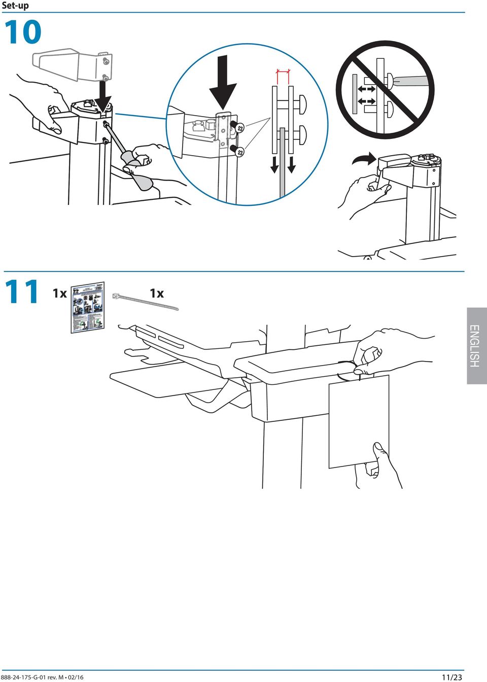
10 Set-up d Placement of CPU's in Secure Storage Area: USFF (Ultra Small Form Factor) Thin Client e DO NOT OBSTRUCT AIR VENTS! Ostructing air vents may cause overheating and result in equipment damage. Center CPU in storage area. To increase space and improve airflow, power rick may e stored under the storage area. If computer with cales is too wide, then follow these instructions. 1 2 f 9 10/23

11 Set-up /23
12 Adjustment 12 It is important that you adjust this product according to the weight of the mounted equipment as descried in the following steps. Any time equipment is added or removed from this product, resulting in a change in the weight of the mounted load, you should repeat these adjustment steps to ensure safe and optimum operation. Adjustments should move smoothly and easily through the full range of motion and stay where you set it. If adjustments are difficult and do not stay in the desired position, follow the instructions to loosen or tighten the tension to create a smooth, easy adjustment motion. Depending on your product and the adjustment, it may take several turns to notice a difference. a Lift Up and down Release Brake to move riser. Follow these instructions to tighten or loosen tension. 14mm (9/16") NOTE: Adjustment may require revolutions. M4 x 8mm Tilt Forward and Backward Loosen kno, tilt Display to desired position then retighten kno. 12/23

13 Adjustment c Lift Up and down Follow these instructions to tighten or loosen tension. 10mm To Stop Independent LCD Lift For heavier Displays or when using a Talet PC, you can keep the LCD Lift from moving out of position, y installing this screw into one of the three holes on the ack of the riser depending on the desired height. M4 x 8mm With Independent LCD Lift: 6-14 ls ( kg) Without Independent LCD Lift: 20 ls (9 kg) WARNING AVERTISSEMENT d Pan - Side-to-Side 3. IMPACT HAZARD! MOVING PARTS CAN CRUSH AND CUT. Failure to heed this warning may result in serious personal injury or property damage! Raise monitor to top of vertical adjustment BEFORE removing. DO NOT remove Stop Screw without monitor attached. Doing so will cause monitor pivot to shoot up rapidly and may cause personal injury. DANGER D IMPACT! LES PARTIES EN MOUVEMENT PEUVENT ÉCRASER ET COUPER. Il existe un risque de lessure corporelle ou d endommagement matériel en cas de non respect de cet avertissement. Élevez l écran au plus haut de l ajustement vertical AVANT de le retirer. NE retirez PAS la vis d arrêt avant que l écran soit fixé. Dans un tel cas, le pivot d'écran se relèverait rapidement et cela pourrait engendrer des lessures Follow these instructions to tighten or loosen tension. 13/23

14 Battery Charge/Discharge 13 Plug Cart's Power Cord into wall outlet. Initial Power on/charge Battery (takes aproximately 7 hours to charge) a Turn on power system y holding power utton down for c 1-3 seconds. With cart's power cord plugged into the wall outlet, wait until cart is at 100% charge. (takes aproximately up to 7 hours to charge) Do Not stretch coiled cord further than 8 feet (2.5 meters), damage to the cord may occur. 8hrs CAUTION: There is no on/off switch on this equipment; the AC power cord is the only power disconnect. The socket outlet should e easily accessile and should e installed near the equipment. This power system interface will alert you to the percentage of charge remaining in the cart attery with a series of steady or flashing red, yellow or green lights, and an alarm that will eep when charge gets elow 30%. Rememer, the attery needs to e charged to 100% every day, and you can use the cart while charging, so plug-in cord as often as possile to avoid running out of power! NOTE: Put monitor in power save mode to optimize attery run time. Battery has 100% charge. Light flashes when charging (power cord plugged into wall outlet) Allow attery to continue charging until light stops flashing. After light stops flashing, it is OK to unplug the power cord from the wall. You can use cart while charging. Battery has less than 90% charge. Battery has less than 70% charge. Battery has less than 50% charge. Battery has less than 30% charge. Light is red and alarm eeps. Plug-in power cord and charge to 100%! You can use cart while charging. When lit, alarm is enaled and will eep when attery charge gets elow 30%. For details on enaling and disaling alarm contact Ergotron Customer Care. Alarm Mute utton. Pressing this will temporarily mute alarm. Power utton for internal power system outlets. Pressing this will provide or remove power to/ from components plugged into the internal outlets. When lit, the power system is on. When dark, power system is off. 14 NOTE: Frequent operation of the cart while attery charge levels are elow 30% will significantly reduce the life of your attery and may void your attery warranty. Keyoard Light 1. Turn Computer on. 2. Test Keyoard Light. Keyoard Light will automatically turn off after 15 minutes if not manually turned off. 14/23
, damage to the cord may occur. 8hrs 7 07.00 CAUTION: There is no on/off switch on this equipment; the AC power cord is the only power disconnect.")
15 How to Change Fuse and Reset Circuit Breakers Turn off all mounted equipment. Disconnect Power System from power source Turn power system off y holding down the AC Outlet Power utton for 1-3 seconds. Power light will shut off. 4 5 Amp Fuse Recommended: Littelfuse HXP 5 Before reseting circuit reakers, contact Ergotron to determine cause of trip. FUSE RATING VOLTAGE 250V CURRENT 5A OPERATING SPEED FAST-ACTING BREAKING CAPACITY 250VAC 6 15/23

16 How to Change Power System Batteries WARNING: RISK OF ELECTRICAL DISCHARGE Do NOT swap attery cales, doing so will cause arcing and trip the circuit reaker. Do not remove or replace the atteries while cart is located in an oxygen rich or hazardous environment, arcing may occur and cause comustion. Replace first attery efore removing second attery to reduce the risk of cales touching terminals and causing arcing. Always replace oth atteries! Replace first attery efore removing second attery. Replace atteries with same Amp/Hour rating atteries only. Only Ergotron-specified atteries may e used in the StyleView Power System. Please call customer care for more details. Recycle attery or contact Ergotron for proper attery disposal guidelines. LEAD BATTERY 33 Amp-Hour Batteries WARNING AVERTISSEMENT BATTERY REPLACEMENT The power module is configured for two, 33 -Ah atteries. Only the following atteries are compatile with this system: B&B EP33-12 SBS S Longway 6FM33G Vision 6FM33D Vision 6FM33HD-X PBQ PBQ33-12L Werker WKA12-33C Werker WKA12-35C Duracell Dura 12-35C Installing atteries other than the 33 -Ah listed aove will void the product warranty. Failure to heed this warning may result in severe damage to atteries, power module and possile fire hazard. REMPLACEMENT DE LA BATTERIE Le module d alimentation est configuré pour deux atteries 33 A-h. Seules les atteries suivantes sont compatiles avec ce système : B&B EP33-12 SBS S Longway 6FM33G Vision 6FM33D Vision 6FM33HD-X PBQ PBQ33-12L Werker WKA12-33C Werker WKA12-35C Duracell Dura 12-35C L installation de atteries autres que les atteries 33 A-h citées ci-dessus annulera la garantie du produit. Si vous ne vous conformez pas à cette précaution d utilisation, les atteries et le module d alimentation risquent d être sérieusement endommagés, ce qui pourrait provoquer un incendie a Turn off all mounted equipment. Disconnect Power System from power source. c Turn power system off y holding down the AC Outlet Power utton for 1-3 seconds. Power light will shut off. 2 a Turn oth circuit reakers to "OFF". 3 Caution: Do NOT swap attery cales, doing so will cause sparking and trip the circuit reaker. a c 10mm (3/8") Black Red d Caution: Remove Black (-) efore removing Red (+). LEAD BATTERY Recycle attery or contact Ergotron for proper attery disposal guidelines. e f Red g h Black Caution: Connect Red (+) efore connecting Black (-). 16/23

17 How to Change Power System Batteries 4 a Caution: Replace only one attery at a time. Do NOT swap attery cales, doing so will cause sparking and trip the circuit reakers. Black c Red Caution: Remove Black (-) efore removing Red (+). d LEAD BATTERY Recycle attery or contact Ergotron for proper attery disposal guidelines. e f g Black h 5 a Red Caution: Connect Red (+) efore connecting Black (-). 6 Follow Battery Charge/Discharge Initial Power on steps a,, c. 17/23

18 Cart Storage Instructions Short Term Storage - If the Power System will e idle for up to 3 months, the attery should e fully charged efore storage. Long Term Storage - If the Power System will e idle for 3 months or more, the attery should e removed from the cart and recharged during storage. Short Term Storage - If the Power System will e idle for up to 3 months, the attery should e fully charged efore storage. 1 3 Turn off all mounted equipment. a 2 Plug power cord into appropriate wall outlet to fully charge attery to 100% (all indicator lights will e illuminated). Power system must e fully charged efore storing! Once attery has een charged to 100%, turn power system off. a. Turn power system off y holding down the AC Outlet Power utton for 1-3 seconds. Power light will shut off.. Turn oth circuit reakers to "OFF". NOTICE: Warranty on fully charged atteries left in an unused state for more than three (3) consecutive months is automatically void. Warranty on fully discharged atteries left in an unused state for more than three (3) consecutive days is automatically void. Long Term Storage - If the Power System will e idle for 3 months or more, the attery should e removed from the cart and recharged during storage. WARNING: Do not remove or replace the atteries while cart is located in an oxygen rich or hazardous environment. Sparking may occur. 1 Turn off all mounted equipment. Disconnect Power System from power source. 2 3 Turn power system off y holding down the AC Outlet Power utton for 1-3 seconds. Power light will shut off. 4 5 Turn oth circuit reakers to "OFF". 6 7 Black Caution: Remove Black (-) efore removing Red (+). Store attery in cool, dry area while Cart is out of use. Optimal 9 10 storage temperature is 15 C/59 F. Battery voltage should e checked every three (3) months. If voltage drops elow 12.5VDC, fully recharge attery. Contact Ergotron Customer Care for information aout how storage might impact the attery warranty. Red 8 18/23
. Power system must e fully charged efore storing!")
19 Ergonomics Working customize - to your size 1 Set top of monitor screen aout one inch elow eye level - Release rake and lift or lower riser as needed. 2 Tilt screen for comfortale viewing and to reduce eye and neck strain. 3 Pull keyoard tray forward and position mouse tray on right or left, as needed. 4 Work with elows ent at aout 90 to minimize muscle strain. 5 If the riser moves up and down with difficulty, or if it drifts out of set position, consult the product manual for adjustment information. 6 Stay in charge! Powered carts should e plugged into outlet as often as possile to keep attery charged and computer running. 2 1 Moving stow - efore you go 1 During normal movement, release rake and lower worksurface to lowest position for optimal staility and unostructed view. 2 Tuck away open trays and return mouse, scanner and other accessories to their places. 3 Unlock oth front casters. 4 Push cart from rear with elows ent at aout 90 to maximize control and minimize muscle strain. 5 Don t run out! Before moving, make sure cord is unplugged from outlet and hooked to asket for safe travel. Rememer, charge attery fully 100% every day! Maintenance & Safety Hazard Symols Review The Meaning of Symols appearing in this Guide, on the Cart or on the Power System These symols alert you to a safety condition that demands your attention. You should e ale to recognize and understand the significance of the following Safety Hazards if you encounter them on the Cart or within Cart documentation such as this Set-up Guide. Symol Signal Word/ Color DANGER WARNING Level of Hazard Indicates an imminently hazardous situation which, if not avoided, will result in death or serious injury. Indicates a potentially hazardous situation which, if not avoided, could result in death or serious injury. 3 EQUIPMENT & ACCESSORIES DISPOSAL 1. Please dispose of all atteries in accordance with local law 2. All Electronics should e recycled through an electronics recycler. 3. Remaining plastics and metals can e recycled through a commercial recycler. CAUTION CAUTION Indicates a potentially hazardous situation which, if not avoided, may result in minor or moderate injury. Used without the safety alert symol indicates a potentially hazardous situation which, if not avoided, may result in property damage. INSTRUCTIONS Follow operating instructions. INSTRUCTIONS Follow operating instructions. POWER "ON" / "OFF" (push-push) NOTE: Each position "ON" / "OFF" is a stale position. 19/23

20 Maintenance & Safety Cleaning and Maintenance The following procedures are not guaranteed to control infection. The hospital infection control administrator or epidemiologist should e consulted regarding cleaning procedures and processes. To avoid risk of electric shock, do not expose electrical components to water, cleaning solutions or other potentially corrosive liquids or sustances. Do not immerse Cart or Cart components in liquid or allow liquids to flow into the Cart. Wipe all cleaners off surface immediately using a damp cloth. Thoroughly dry surface after cleaning. Do not use flammale cleaners on Cart surfaces due to close proximity of electrical power and equipment. All paints and plastic Cart components will withstand cleaning y most commonly used, diluted, non-arasive solutions such as quaternary ammonia compounds, ammonia enzyme cleaners, leach or alcohol solutions. Pen and permanent and dry erase markers can e removed with 91% isopropyl alcohol and a soft cloth. Iodine stains can e removed with commonly used cleaners and a soft cloth. Never use steel wool or other arasive materials that will damage the surface finish. Do not use strong solvents such as trichloroethylene and acetone. These solvents will damage the surface finish. It is recommended that any cleaning solution e tested on a small, inconspicuous area to ensure surface is not harmed. Adjustment, Service, Replacement - DO NOT attempt to adjust, service or replace any part of the StyleView Cart unless directed to do so through Ergotron-approved documentation (i.e. installation instructions). Only Ergotron, Inc. or an Ergotron-certified entity may adjust, service or replace StyleView Cart components. If any component on the Cart is missing or damaged, the Cart must not e used, contact Ergotron Customer Care immediately to request a replacement part. Cales - Keep cales neatly organized on the Cart (a variety of solutions are provided with your cart for this purpose). Excess cales should e routed away from moving components with cale clips. Review Cale Routing section of this guide, or contact Ergotron Customer Care for more information. Casters - Check casters periodically to make sure they are clean and free of deris that would prevent smooth travel. Avoid moving Cart across uneven, dirty or damaged surfaces. Customer Equipment- Make sure equipment is alanced and mounted securely to Cart. Do not reposition Cart components on riser or tower unless instructed to do so in the installation instructions. Moving Cart components too high or too low on the Riser may create an unstale condition, leading to equipment damage or even personal injury. Contact Ergotron Customer Care for information aout moving Cart components. Safety Alerts Associated with this Product The following Warnings/Cautions appear in this reference guide or on the cart: NOTE: Failure to adhere to these guidelines may result in equipment damage or personal injury. CAUTION: The lift rake helps stalilize the worksurface and keyoard tray during normal use ut it DOES NOT increase load capacity. DO NOT load riser with equipment totaling more than the maximum weight capacity specified y Ergotron. Ensure optimum lift function y testing and if necessary, re-adjusting tension whenever the weight mounted to the riser changes (i.e., equipment is removed or added). See "Set Riser Lift Tension" adjustment instructions. CAUTION: Do not operate StyleView Cart with missing or damaged components! Do not remove, modify or sustitute Cart components without consulting Ergotron. If you encounter prolems with Cart installation or operation, contact Ergotron Customer Care. CAUTION: DO NOT overtighten fasteners. Overtightening may cause damage to your equipment. WARNING: Stored Energy Hazard: The worksurface lift mechanism is under tension and will move up rapidly, on its own, as soon as attached equipment is removed. For this reason, DO NOT remove equipment unless the worksurface has een moved to the highest position on the tower! Failure to follow this instruction may result in serious personal injury and/or equipment damage! When Shipping the cart, set the worksurface lift mechanism to the lowest tension setting. CAUTION: DO NOT loosen, tighten or remove any other nuts or olts on the riser or top of tower. Tampering with nuts or olts may result in an unstale Cart, leading to equipment damage and/or personal injury. CAUTION: Release Lift Brake efore moving work surface! Moving work surface while Lift Brake is engaged may cause serious damage to Lift Engine. WARNING: In the event that repair of the StyleView Cart is needed, contact Ergotron Customer Care immediately. Cart repair can only e performed y Ergotron, Inc. or y an Ergotron authorized agent. WARNING: This cart is not intended for use in a flammale, anesthetic mixture or oxygen rich environment. Configuration & Safety Additional multiple socket-outlet or extension cord shall not e connected to the medical system. When used in a Medical Electrical system, connect only equipment that complies with IEC, ISO, UL/ANSI, or CSA standards that are relevant to that equipment. Risk of shock or personal injury when connecting non-medical equipment supplied as part of a system directly to the wall outlet when non-medical equipment is intended to e supplied y the multiple socket outlet. Risk of shock or personal injury when connecting any equipment that has not een supplied as part of the medical system to the multiple socket outlet. 20/23

21 Maintenance & Safety Recommended Periodic Inspection and Maintenance Component Action How often By whom UI, Ethernet, USB cales Fan on side of CPU compartment Inspect for wear, pinching, ad connectors Inspect for dust at intake, vacuum as required using a vacuum cleaner that DOES NOT generate ESD (Electrostatic Discharge) Monthly Monthly Any user Any user Casters Inspect for wear and deris Monthly Any user Maximum Load Power System SLA atteries Power Module Battery harness Inspect to ensure that maximum recommended loads are not exceeded Replace lead acid atteries 1,2 Inspect for dust at intake, vacuum as required using a vacuum cleaner that DOES NOT generate ESD (Electrostatic Discharge) Inspect for wear, cracking, pinching, or other damage Daily When instructed y StyleLink or when attery runtime is 80% of original runtime Monthly Monthly Any user IT Personnel IT Personnel IT Personnel Inspect for wear, damage, or Coiled Cord Weekly Any user stretching. 1. Please dispose of all atteries in accordance with local law 2. Always replace with similar size attery (33 A-h to replace 33 A-h) and always replace in pairs DANGER! ELECTRICAL CORDS CAN BE HAZARDOUS Misuse Can Result in FIRE or DEATH y ELECTRICAL SHOCK. LES CORDONS ELECTRIQUES PEUVENT ETRE DANGEREUX Une mauvaise utilisation peut provoquer un INCENDIE ou la MORT par CHOC ELECTRIQUE THIS IS A POLARIZED CORD - HOSPITAL GRADE ONLY Earth Bond Test: To ensure safety grounding etween the power cord ground connection and any accessile metal parts on the cart, although not mandatory, the following test is recommended to e performed every two years using a calirated medical device safety analyzer. The procedure is as follows: 1. Disconnect the cart from mains power (unplug cart from the wall). 2. Remove power from internal power system outlets y pressing the power utton on the Power System Interface. 3. Set up Earth Bond Test per the medical device safety analyzer instructions. 4. Connect the Cart power cord to the medical device safety analyzer. 5. Remove cover to access Lift Tension Adjustment point. 6. Attach second medical safety device analyzer proe to Lift Tension Adjustment point on Cart. 7. Perform Test (25 amps). 8. Ensure Earth Bond is less than or equal to 0.2-ohms. 9. Remove medical device safety analyzer connections to Cart, replace cover over Lift Tension Adjustment point, return the Cart to service. Insulation Resistance Test: To ensure mains power lines are adequately insulated from earth ground, the following test, although not mandatory, is recommended to e performed annually using a calirated medical device safety analyzer. The procedure is as follows: 1. Disconnect the cart from mains power (unplug cart from the wall). 2. Remove power from internal power system outlets y pressing the power utton on the Power System Interface. 3. Set up the Insulation Resistance Test per the medical device safety analyzer instructions. 4. Connect the Cart power cord to the medical device safety analyzer. 5. Perform test (500 V). 6. Ensure Insulation Resistance is greater than or equal to 1 Mohms. 7. Remove medical device safety analyzer connections to Cart and return Cart to service. 21/23
22 Maintenance & Safety Ergotron Electromagnetic Guidance and Manufacturer s Declaration Guidance and Manufacturer s Declaration Electromagnetic Emissions The Powered Computer Cart is intended for use in the electromagnetic environment specified elow. The customer or the user of the Powered Computer Cart should assure that it is used in such an environment. Emissions Test Compliance Electromagnetic environment guidance RF Emissions CISPR 11 RF Emissions CISPR 11 Harmonic Emissions IEC Voltage fluctuations/ flicker emissions IEC Group 1 Class A Class A Complies The Powered Computer Cart uses RF energy only for its internal function. Therefore, its RF emissions are very low and unlikely to cause any interference in neary electronic equipment. The Powered Computer Cart is suitale for use in all estalishments other than domestic and those directly connected to the pulic low-voltage power supply network that supplies uildings used for domestic purposes. Guidance and Manufacturer s Declaration Electromagnetic Immunity The Powered Computer Cart is intended for use in the electromagnetic environment specified elow. The customer or the user of the Powered Computer Cart should assure that it is used in such an environment. Immunity Test IEC Test Level Electrostatic Discharge (ESD) IEC Electrical Fast Transient/Burst IEC Surge IEC Voltage Dips, short interruptions, and voltage variations on power supply input lines IEC Power Frequency (50/60 Hz) Magnetic Field IEC ±6 kv contact ±8 kv air ±2 kv for power supply lines ±1 kv for input/output lines ±1 kv differential mode ±2 kv common mode <5% U T (>95% dip in U T ) for 0.5 cycle 40% U T (60% dip in U T) for 5 cycles 70% U T (30% dip in U T ) for 25 cycles <5% U T (>95% dip in U T ) for 5 seconds Compliance Level Complies Complies Complies Complies Electromagnetic environment - guidance Floors should e wood, concrete, or ceramic tile. If floors are covered with synthetic material, the relative humidity should e at least 30% Mains power quality should e that of a typical commercial or hospital environment. Mains power quality should e that of a typical commercial or hospital environment Mains power quality should e that of a typical commercial or hospital environment. 3 A/m Complies Power frequency magnetic fields should e at levels characteristic of a typical location in a typical commercial or hospital environment. Note: U T is the AC mains voltage prior to application of the test level 22/23
23 Dimensions 14.63" (372 mm) 7" - 12" ( mm) 50.5" (1283 mm) 3.4" (86 mm) 13.4" (340 mm) 40" (1016 mm) 8.5" (216 mm) 2.5" (64mm) 31" - 51" ( mm) 17.5" (445 mm) 19.75" (502 mm) 2.9" (74 mm) 31" (787 mm) 23" - 43" ( mm) 22.38" (568 mm) 13" (330 mm) 1.75" (44 mm) 17" (432 mm) 4" (102 mm) 15.5" (394 mm) 18.3" (465 mm) **< 4" (102 mm) *< 17.63" (448 mm) **< 2.75" (70 mm) CPU Compartment When figuring dimensions, include mounted accessories, protruding cales and port replicators or docking stations. Front View Side View * < 4" (102 mm) < 12.25" (311 mm) < 12.25" (311 mm) < 14.75" (375 mm)** < 13" (330 mm) < 1.38" (35 mm) < 2.3" (58 mm) **< 8" (203 mm) **< 2.75" (70 mm) Top View < 2.75" (70 mm) *< 21.75" (552 mm) *< 17.75" (451 mm) **< 7.75" (197 mm) **< 4.25" (108 mm) 2016 Ergotron, Inc. All rights reserved. 23/23
StyleView SV41 Electronic Medical Records (EMR) Cart with Laptop Mount
 Cart with Laptop Mount") User Guide StyleView SV4 Electronic Medical Records (EMR) Cart with Laptop Mount Features & Specifications... 3 Set-up... 4 - Adjustment... 0 Ergonomics... Maintenance & Safety... - 2 Dimensions...3 For
User Guide StyleView SV4 Electronic Medical Records (EMR) Cart with Laptop Mount Features & Specifications... 3 Set-up... 4 - Adjustment... 0 Ergonomics... Maintenance & Safety... - 2 Dimensions...3 For
StyleView SV40 Electronic Medical Records (EMR) Cart with LCD Mount. www.ergotron.com. 10x 2x. 1x 1x. User Guide
 Cart with LCD Mount. www.ergotron.com. 10x 2x. 1x 1x. User Guide") User Guide StyleView SV40 Electronic Medical Records (EMR) Cart with LCD Mount For the latest User Installation Guide and StyleLink Software Download please visit: Encontrará la versión más reciente del
User Guide StyleView SV40 Electronic Medical Records (EMR) Cart with LCD Mount For the latest User Installation Guide and StyleLink Software Download please visit: Encontrará la versión más reciente del
StyleView SV42 Electronic Medical Records (EMR) Cart with Laptop Mount. http://4support.ergotron.com. User Guide
 Cart with Laptop Mount. http://4support.ergotron.com. User Guide") User Guide StyleView SV42 Electronic Medical Records (EMR) Cart with Laptop Mount For the latest User Installation Guide and StyleLink Software Download please visit: Encontrará la versión más reciente
User Guide StyleView SV42 Electronic Medical Records (EMR) Cart with Laptop Mount For the latest User Installation Guide and StyleLink Software Download please visit: Encontrará la versión más reciente
StyleView Telepresence Cart
 User Guide StyleView Telepresence Cart with Single LCD For the latest User Installation Guide and StyleLink Software Download please visit: Encontrará la versión más reciente del manual de instalación
StyleView SV42 Electronic Medical Records (EMR) Cart with Laptop Mount and LiFe Power System
 Cart with Laptop Mount and LiFe Power System") User Guide StyleView SV42 Electronic Medical Records (EMR) Cart with Laptop Mount and LiFe Power System StyleView powered carts provide electrical AC power for mobile point of care computing equipment
User Guide StyleView SV42 Electronic Medical Records (EMR) Cart with Laptop Mount and LiFe Power System StyleView powered carts provide electrical AC power for mobile point of care computing equipment
StyleView SV40 Electronic Medical Records (EMR) Cart with Laptop Mount
 Cart with Laptop Mount") User Guide StyleView SV40 Electronic Medical Records (EMR) Cart with Laptop Mount For the latest User Installation Guide and StyleLink Software Download please visit: Encontrará la versión más reciente
User Guide StyleView SV40 Electronic Medical Records (EMR) Cart with Laptop Mount For the latest User Installation Guide and StyleLink Software Download please visit: Encontrará la versión más reciente
StyleView SV42 Electronic Medical Records (EMR) Cart with LCD Mount and LiFe Power System
 Cart with LCD Mount and LiFe Power System") User Guide StyleView SV42 Electronic Medical Records (EMR) Cart with LCD Mount and LiFe Power System StyleView powered carts provide electrical AC power for mobile point of care computing equipment in
User Guide StyleView SV42 Electronic Medical Records (EMR) Cart with LCD Mount and LiFe Power System StyleView powered carts provide electrical AC power for mobile point of care computing equipment in
StyleView Telepresence Cart
 User Guide StyleView Telepresence Cart with Single LCD For the latest User Installation Guide and StyleLink Software Download please visit: Encontrará la versión más reciente del manual de instalación
StyleView Telepresence Cart
 User Guide StyleView Telepresence Cart with Dual LCD For the latest User Installation Guide and StyleLink Software Download please visit: Encontrará la versión más reciente del manual de instalación del
StyleView SV44 Cart. with Laptop Mount and LiFe Power System. User Guide ENGLISH
 User Guide StyleView SV44 Cart with Laptop Mount and LiFe Power System StyleView powered carts provide electrical AC power for mobile point of care computing equipment in a healthcare environment. The
StyleView SV41 Electronic Medical Records (EMR) Cart with Laptop Mount. http://4support.ergotron.com. User Guide
 Cart with Laptop Mount. http://4support.ergotron.com. User Guide") User Guide StyleView SV41 Electronic Medical Records (EMR) Cart with Laptop Mount For the latest User Installation Guide and StyleLink Software Download please visit: Encontrará la versión más reciente
User Guide StyleView SV41 Electronic Medical Records (EMR) Cart with Laptop Mount For the latest User Installation Guide and StyleLink Software Download please visit: Encontrará la versión más reciente
StyleView SV40 Electronic Medical Records (EMR) Cart with Laptop Mount
 Cart with Laptop Mount") User Guide StyleView SV40 Electronic Medical Records (EMR) Cart with Laptop Mount Features & Specifications... 3 Dimensions...3 Set-up... 4-9 Adjustment... 9 Ergonomics...9 Maintenance & Safety...9-10
User Guide StyleView SV40 Electronic Medical Records (EMR) Cart with Laptop Mount Features & Specifications... 3 Dimensions...3 Set-up... 4-9 Adjustment... 9 Ergonomics...9 Maintenance & Safety...9-10
Zip40 Charging Cart. User's Guide. Components. Tools Needed ENGLISH. For the latest User Installation Guide please visit: www.ergotron.com.
 User's Guide Zip40 Charging Cart Components 2x 9x Tools Needed For the latest User Installation Guide please visit: www.ergotron.com User's Guide - English Guía del usuario - Español Manuel de l utilisateur
StyleView SV41 Electronic Medical Records (EMR) Cart with Laptop Mount
 Cart with Laptop Mount") For the latest User Installation Guide and StyleLink Software Download please visit: Encontrará la versión más reciente del manual de instalación del usuario y el software de StyleLink en: Si vous souhaitez
For the latest User Installation Guide and StyleLink Software Download please visit: Encontrará la versión más reciente del manual de instalación del usuario y el software de StyleLink en: Si vous souhaitez
StyleView SV42 Electronic Medical Records (EMR) Cart with LCD Mount and LiFe Power System
 Cart with LCD Mount and LiFe Power System") For the latest User Installation Guide and StyleLink Software Download please visit: Encontrará la versión más reciente del manual de instalación del usuario y el software de StyleLink en: Si vous souhaitez
For the latest User Installation Guide and StyleLink Software Download please visit: Encontrará la versión más reciente del manual de instalación del usuario y el software de StyleLink en: Si vous souhaitez
Tablet Management Rack 16
 Tablet Management Rack 16 User's Guide Table of Contents Hazard Symbols Review... 2 Components... 2 Charging Set-up... 3-4 LED and Syncing... 4-5 Cleaning and Maintenance... 6 Specifications... 6 Service
Regulatory Compliance Statement
 Regulatory Compliance Statement 0560 EU Declaration of Conformity The declaration of conformity may be consulted at www.kobo.com/userguides SAR Limits The exposure standard for wireless devices employs
EKOS Cart. Instructions for Use
 EKOS Cart Instructions for Use EKOS Corporation 11911 North Creek Parkway South Bothell, WA 98011 USA (425) 415-3100 (tel) (425) 415-3102 (fax) info@ekoscorp.com (e-mail) - 1-4913-002 REV E Intended Use
Power Supply Guide Version 1.0 for D-Show
 Power Supply Guide Version 1.0 for D-Show Digidesign 2001 Junipero Serra Boulevard Daly City, CA 94014-3886 USA tel: 650 731 6300 fax: 650 731 6399 Technical Support (USA) tel: 650 731 6100 fax: 650 731
READ AND FOLLOW ALL SAFETY INSTRUCTIONS 1. DANGER RISK OF SHOCK DISCONNECT POWER BEFORE INSTALLATION
 UR Series LED Upgrade Kit Includes: 48" Linear Option IMPORTANT SAFEGUARDS When using electrical equipment, basic safety precautions should always be followed including the following: READ AND FOLLOW ALL
Gateway Port Replicator User Guide
 Gateway Port Replicator User Guide Using the Port Replicator Identifying features Connecting and disconnecting the port replicator 1 Using the Port Replicator Top Power button Component Icon Description
Broadband Telecommunications Drop Amplifier
 INSTALL SHEET BDA Broadband Telecommunications Drop Amplifier Introduction The Broadband Telecommunications Drop Amplifier (BDA) is a two-way, 1 GHz amplifier designed for customer-premise amplification
SNQ-60x0-320 Series Data Center Switch. Quick Installation Guide
 Introduction This guide is to assist the reader with the most basic form of installation and connection to switches in this series. As there is more than one switch in this series, the diagrams might slightly
Daker DK 1, 2, 3 kva. Manuel d installation Installation manual. Part. LE05334AC-07/13-01 GF
 Daker DK 1, 2, 3 kva Manuel d installation Installation manual Part. LE05334AC-07/13-01 GF Daker DK 1, 2, 3 kva Index 1 Introduction 24 2 Conditions of use 24 3 LCD Panel 25 4 Installation 28 5 UPS communicator
767 Diagnostic System
 767 Diagnostic System 3.5v 767 Wall Transformer Patent Pending Listed to: UL 60601-1 CSA C22.2 No. 601 Thank you for purchasing the Welch Allyn 3.5v 767 Wall Transformer. This manual is meant to provide
GSM-EXT Cable Assembly Installation Guide
 GSM-EXT Cable Assembly Installation Guide For Documentation and Online Support: http://www.security.honeywell.com/hsc/resources/mywebtech General Information The GSM-EXT cable assembly is used to connect
MCR1900 Media Converter 19-Slot Chassis
 MCR1900 Media Converter 19-Slot Chassis Installation Guide Part #5500304-11 Copyright Statement This document must not be reproduced in any way whatsoever, either printed or electronically, without the
Operation Instructions PowerCool Series
 Operation Instructions PowerCool Series TOP VIEW BOTTOM VIEW PDCOOL-05RA PDCOOL-00RK PDCOOL-5R PDCOOL-0R ALSO AVAILABLE Thank you for purchasing the PowerCool Series component cooler and power distribution.
How To Use A Power Supply Unit (Upu)
") BRAVER UPS (Uninterruptible Power System) User s Manual Safety CAUTION! This UPS utilizes voltages that may be hazardous. Do not attempt to disassemble the unit. The unit contains no user replaceable parts.
BRAVER UPS (Uninterruptible Power System) User s Manual Safety CAUTION! This UPS utilizes voltages that may be hazardous. Do not attempt to disassemble the unit. The unit contains no user replaceable parts.
WF720 Wireless Home Phone User Manual
 WF720 Wireless Home Phone User Manual Content Getting to Know Your Device... 3 Appearance...3 LED Indicator...4 Device Installation... 5 Before You Begin...5 Installing the SIM Card and the Battery...5
esata External Storage
 esata External Storage Operation Manual DA-ES110 Before reading this manual This operation manual contains basic instruction on installing and using esata External Storage, an IDIS product. Users who are
When you switch off your system, or mute the sound, the red indicator light appears immediately, indicating that the subwoofer is not in use.
 BeoLab 11 Guide WARNING: To reduce the risk of fire or electric shock, do not expose this appliance to rain or moisture. Do not expose this equip ment to dripping or splashing and ensure that no objects
Ergotron StyleView Cart
 StyleView EMR Laptop Cart, SV40 19.6" (499 mm) 17.2" (438 mm) 2" (50 mm) 28.7" (728 mm) 12. Laptop Compartment 22" (562 mm) 14.9" (378 mm) 18.3" (466 mm) mounted accessories, protruding cables and port
About the HotWire 7900 10-Slot Standalone Shelf
 TM HotWire Model 7900 10-Slot Standalone Shelf Installation Instructions Document Number 7900-A2-GN10-10 About the HotWire 7900 10-Slot Standalone Shelf The HotWire 7900 10-Slot Standalone Shelf is designed
Daily use. Never use alcohol or other solvents to clean any part of the loudspeakers!
 BeoLab 6002 Guide WARNING: To reduce the risk of fire or electric shock, do not expose this appliance to rain or moisture. Do not expose this equip ment to dripping or splashing and ensure that no objects
33.6W Power over Ethernet Waterproof Adapter PoE Plus Single Port Injector for Outdoor Application
 33.6W Power over Ethernet Waterproof Adapter PoE Plus Single Port Injector for Outdoor Application Features Compliant with the IEEE802.3at Standard -40 to +60 C Temperature Range Diagnostic LEDs Full Protection
FCC COMPLIANCE STATEMENT FOR AMERICAN USERS
 FCC COMPLIANCE STATEMENT FOR AMERICAN USERS This equipment has been tested and found to comply with the limits for a CLASS A digital device, pursuant to Part 15 of the FCC Rules. These limits are designed
Uninterruptible Power Supply ERA LED 1.5 ERA LED 2.0 ERA LED 2.6. User s manual
 Uninterruptible Power Supply ERA LED 1.5 ERA LED 2.0 ERA LED 2.6 User s manual Index Safety Warnings... 2 1 Introduction... 3 2 General Characteristics... 4 3 Receipt and site selection... 4 4 EXTERNAL
2013 VTech Printed in China 91-009656-000 US
 Rechargeable Power Pack User s Manual 2013 VTech Printed in China 91-009656-000 US INTRODUCTION The Rechargeable Power Pack makes it easier than ever to keep the InnoTab 3 or InnoTab 3S charged and ready
CAUTION RISK OF ELECTRIC SHOCK DO NOT OPEN
 BeoLab 7-6 Guide CAUTION RISK OF ELECTRIC SHOCK DO NOT OPEN CAUTION: To reduce the risk of electric shock, do not remove cover (or back). No User-serviceable parts inside. Refer servicing to qualified
ATS Overhead Table Shelf System INSTRUCTION MANUAL
 ATS Overhead Table Shelf System INSTRUCTION MANUAL ATS Overhead Table Shelf System Instruction Manual Warranty Newport Corporation warrants this product to be free of defects in material and workmanship
BroadBand PowerShield. User Manual
 BroadBand PowerShield User Manual 990-0375G 12/2006 Chapter 1 General Information The PowerShield provides a power source for broadband telephony and other DC applications. Safety This Safety Guide contains
Owner s Manual. Not suitable for mobile applications. Important Safety Instructions 2. Quick Installation 3. Basic Operation 4. Storage & Service 7
 Register online today for a chance to win a FREE Tripp Lite product! www.tripplite.com/warranty Owner s Manual Internet Office & BC Personal UPS Systems Not suitable for mobile applications. Important
Mobile Data Power Model: MDP-25
 Mobile Data Power Model: MDP-25 Topic Section Features... 2 Operational Features Summary... 2 Back-up Battery Power Internal Charger Voltage Spike Protection RF Noise Filtering Warning of Imminent Loss
REGULINE 600VA / 1000VA REGULATOR USER MANUAL
 REGULINE 600VA / 1000VA REGULATOR USER MANUAL TUNÇMATİK REGULINE SERIES AUTOMATIC VOLTAGE REGULATOR Models: REGULINE 600VA / REGULINE 1000VA Principle of Operation Automatic Voltage Regulators regulate
Outdoor 33.6W Dual Port Passive Power-over-Ethernet Midspan For External Security Cameras and Wireless Access Points
 Outdoor 33.6W Dual Port Passive Power-over-Ethernet Midspan For External Security Cameras and Wireless Access Points Features SELV Compliant No Detection Passive Injector Gigabit Compatible Full Protection
FortiFone QuickStart Guide for FON-370i
 FortiFone QuickStart Guide for FON-370i FortiFone QuickStart Guide for FON-370i Revision 2 August 17, 2015 Copyright 2015 Fortinet, Inc. All rights reserved. Fortinet, FortiGate, FortiCare and FortiGuard,
FOR THE FOLLOWING MODELS: EE-8075W EE-8075O EE-8075R EE-8075BK
 FIREPLACE HEATER FOR THE FOLLOWING MODELS: EE-8075W EE-8075O EE-8075R EE-8075BK If you have any questions about the operation of your fireplace heater, please contact Crane Customer Care. Toll Free: 888-599-0992
15-INCH TFT-LCD MONITOR
 15-INCH TFT-LCD MONITOR 15RTV INSTRUCTION MANUAL Please read this manual thoroughly before use, and keep it handy for future reference. SAFETY INSTRUCTION.2-3 CAUTIONS....4 FCC RF INTERFERENCE STATEMENT.5
CR /Fusion. BEETLE /FUSION Side Combo. Operating Manual
 CR /Fusion BEETLE /FUSION Side Combo Operating Manual The reproduction, transmission or use of this document or its contents is not permitted without express authority. Offenders will be liable for damages.
ColdGuard Bi-PARTING DOOR INSTALLATION INSTRUCTIONS
 EHD TRACK LEVEL, (SET LEVEL ON PLASTIC HEADER. DO NOT PLACE LEVEL ON ALUMINUM TRACK.) TRACK IS FLUSH WITH TOP OF HEADER JUNCTION BOX IDLER PULLEY LOCATOR PINS LOCATOR PINS OPERATOR DOOR STOP JUNCTION BOX
Express5800/120Ed. Rack Mount Kit Installation Procedures PN: 455-01607-001
 Express5800/120Ed Rack Mount Kit Installation Procedures PN: 455-01607-001 Proprietary Notice and Liability Disclaimer The information disclosed in this document, including all designs and related materials,
aseries A13B Mini Bullet Camera User Manual
 aseries A13B Mini Bullet Camera User Manual Thank you for purchasing our product. If there are any questions, or requests, please do not hesitate to contact the dealer. This manual applies to the MicroView
Portable Air Conditioner
 Portable Air Conditioner Owner's Manual Model:3 in 1 12,000 Btu/h Series 3 Please read this owner s manual carefully before operation and retain it for future reference. CONTENTS 1. SUMMARY...1 2. PORTABLE
BeoLab 7-1 BeoLab 7-2. Guide
 BeoLab 7-1 BeoLab 7-2 Guide CAUTION: To reduce the risk of electric shock, do not remove cover (or back). No User-serviceable parts inside. Refer servicing to qualified service personnel. WARNING: To prevent
PowlVac Vacuum Integrity Tester
 Instructions IB-60025B PowlVac Vacuum Integrity Tester POWELL ELECTRICAL MANUFACTURING COMPANY 8550 MOSLEY DRIVE HOUSTON, TEXAS 77075 USA PHONE (713) 944-6900 FAX (713) 947-4453 www.powellelectric.com
USER S GUIDE V:1614-0805-10. BC118 Portable Boombox. For the most up-to-date version of this User s Guide, go to www.gpx.com
 USER S GUIDE V:1614-0805-10 BC118 Portable Boombox For the most up-to-date version of this User s Guide, go to www.gpx.com Warnings and Precautions CAUTION: TO PREVENT ELECTRIC SHOCK, MATCH WIDE BLADE
How To Set Up An Ecm Display On A D210 (D210) (D2) (Ecm) (Emc) (Mcd) (Power Supply) (Mm) (Camellom) (Ios)
 (D2) (Ecm) (Emc) (Mcd) (Power Supply) (Mm) (Camellom) (Ios)") English Customer Display DM-D210 Installation Manual 401285101 CAUTIONS This document shall apply only to the product(s) identified herein. No part of this document may be reproduced, stored in a retrieval
English Customer Display DM-D210 Installation Manual 401285101 CAUTIONS This document shall apply only to the product(s) identified herein. No part of this document may be reproduced, stored in a retrieval
USER S MANUAL. MaxPower 400-600 UPS. Uninterruptible Power System 28-2MAXPO0018
 USER S MANUAL MaxPower 400-600 UPS Uninterruptible Power System 28-2MAXPO0018 IMPORTANT SAFETY INSTRUCTIONS SAVE THESE INSTRUCTIONS This manual contains important instructions for models MaxPower 400 and
12-Volt 10-Amp Regulated Power Supply
 22-506.fm Page 1 Friday, August 6, 1999 12:55 PM Cat. No. 22-506 OWNER S MANUAL Please read before using this equipment. 12-Volt 10-Amp Regulated Power Supply 22-506.fm Page 2 Friday, August 6, 1999 12:55
User s Manual AURORA 1.2K/2.2K
 User s Manual AURORA 1.2K/2.2K Uninterruptible Power System Safety CAUTION This UPS utilizes voltages that may be hazardous. Do not attempt to disassemble the unit. The unit contains no user serviceable
Manual Ranging MultiMeter
 Owner s Manual Manual Ranging MultiMeter Model 82345 CAUTION: Read, understand and follow Safety Rules and Operating Instructions in this manual before using this product.! Safety! Operation! Maintenance!
StorTrends 3400 Hardware Guide for Onsite Support
 StorTrends 3400 Hardware Guide for Onsite Support MAN-3400-SS 11/21/2012 Copyright 1985-2012 American Megatrends, Inc. All rights reserved. American Megatrends, Inc. 5555 Oakbrook Parkway, Building 200
USER MANUAL Stand Alone Power Supply PSQ 2909 / PSQ 3909 / PSQ 4909 PSQ 2920 / PSQ 3920 / PSQ 4920
 USER MANUAL Stand Alone Power Supply PSQ 2909 / PSQ 3909 / PSQ 4909 PSQ 2920 / PSQ 3920 / PSQ 4920 [This page intentionally left blank] Warning for Your Protection 1. Read these instructions. 2. Keep these
First Data FD130 Terminal. Quick Set-up Guide
 First Data FD130 Terminal Quick Set-up Guide Thanks for choosing a First Data Terminal. First Data Terminals are some of the fastest, most secure point-of-sale terminals available. Installation is quick
MICA HEATER INSTRUCTION MANUAL Model No: UHM-786 230V 50Hz 2200W
 MICA HEATER INSTRUCTION MANUAL Model No: UHM-786 230V 50Hz 2200W Safety Precautions To reduce the risk of personal injury or damage to property, basic safety precautions must be observed including the
Mercury Helios 2 ASSEMBLY MANUAL & USER GUIDE
 Mercury Helios 2 ASSEMBLY MANUAL & USER GUIDE TABLE OF CONTENTS INTRODUCTION...1 1.1 MINIMUM SYSTEM REQUIREMENTS 1.1.1 Apple Mac Requirements 1.1.2 PC Requirements 1.1.3 Supported PCIe Cards 1.2 PACKAGE
Wolflite Safety Handlamp H-251E
 Wolflite Safety Handlamp H-251E & H-251 Mk1 & Mk2 Wolflite Safety Handlamp H-251E H 18Y H 17 H 31Y H 21A H 30 H 24 H 26 H 19 H 25 H 03 H 15Y H 22 H 104 H 29 H 66 H 13 H 14 H 09 H 12 H 48 H 11 H 62 H 63
Advantium 2 Plus Alarm
 ADI 9510-B Advantium 2 Plus Alarm INSTALLATION AND OPERATING INSTRUCTIONS Carefully Read These Instructions Before Operating Carefully Read These Controls Corporation of America 1501 Harpers Road Virginia
CAUTION RISK OF ELECTRIC SHOCK DO NOT OPEN
 BeoLab 4000 Guide CAUTION RISK OF ELECTRIC SHOCK DO NOT OPEN CAUTION: To reduce the risk of electric shock, do not remove cover (or back). No User-serviceable parts inside. Refer servicing to qualified
IMPORTANT SAFETY RULES TO FOLLOW
 WARNING FLOOR & CARPET CLEANER Any piece of equipment can be dangerous if not operated properly. YOU are responsible for the safe operation of this equipment. The operator must carefully read and follow
PORTABLE ALARM CLOCK. Dual Alarm. FM Radio. Wake-up Sounds. USB Phone Charger G-1CR
 G-BUZZ PORTABLE ALARM CLOCK Dual Alarm FM Radio Wake-up Sounds USB Phone Charger G-1CR Welcome Alarm clocks can be boring. Get ready to shake things up with your new G-BUZZ. Slap the snooze for more ZZZ
CAUTION RISK OF ELECTRIC SHOCK DO NOT OPEN
 BeoLab 4 Guide CAUTION RISK OF ELECTRIC SHOCK DO NOT OPEN CAUTION: To reduce the risk of electric shock, do not remove cover (or back). No User-serviceable parts inside. Refer servicing to qualified service
Ingenico. User Guide 5100M. Secure transaction and payment solutions
 User Guide Ingenico 5100M Secure transaction and payment solutions Ingenico 5100 M Contents 1 Presentation... 5 1.1 Overview of Ingenico 5100... 6 1.2 Keyboard details and functionality... 7 2 Use...
BPM Series. Metered Rack Mount PDUs. Quick Start Guide. Models Covered:
 WTI Part No.: 13963 Rev.: PM Series Metered Rack Mount PDUs Models Covered: PM-8HS20-1 PM-16VS30-1 PM-24VS30-1 PM-24VS30-D PM-8HS20-2 PM-16VS30-2 PM-24VS30-2 PM-24VS30-Y PM-16VS20-1 PM-24VS20-1 PM-24VS20-D
4.3-inch Back-Up Camera
 TM 4.-inch Back-Up Camera Model No.: PKC0BU4 Owner s Manual and Warranty Information Read these instructions completely before using this product. Retain this Owner s Manual for future reference. INTRODUCTION
Square D Clipsal DIN-Rail Four-Channel Auxiliary Input Unit
 Square D Clipsal DIN-Rail Four-Channel Auxiliary Input Unit SLCLE5504AUX for Use with Wired C-Bus Networks Instruction Bulletin Retain for future use. Square D Clipsal DIN-Rail Four-Channel Auxiliary Input
Operation Manual. Multi Channel Power Amplifier DPA-430L
 Operation Manual Multi Channel Power Amplifier DPA-430L Welcome A personal welcome to you from the management and employees of Inter-M All of the co-workers here at Inter-M are dedicated to providing excellent
USER GUIDE TURBOCORD TM PORTABLE CHARGER 120V/240V: DUAL VOLTAGE. AeroVironment EV Solutions
 USER GUIDE TURBOCORD TM PORTABLE CHARGER 120V/240V: DUAL VOLTAGE AeroVironment EV Solutions 2013 AeroVironment, Inc. All rights reserved. AeroVironment, EV Solutions, and the AeroVironment logo are trademarks
Cisco TelePresence MCU 4500 Series safety and compliance information
 Cisco TelePresence MCU 4500 Series safety and compliance information On this page: Safety information symbols Operating guidelines Safety warnings Technical specifications Compliance information WEEE information
DRM75A 230V 20/100A DIN rail single phase two wire energy meter
 DRM75A 230V 20/100A DIN rail single phase two wire energy meter 1.1 Safety instruction 1.2 Foreword 1.3 Performance criteria 1.4 Specifications 1.5 Basic errors 1.6 Description 1.7 Dimensions 1.8 Installation
User s Manual Before using the inverter, you need to read and save the safety instructions.
 User s Manual Before using the inverter, you need to read and save the safety instructions. STI SERIES (STI200, STI300, STI500, STI700, STI1000) Power Frequency Pure Sine Wave Inverter The information
350, 500, 650 and 1000 MODELS
 P D Technology Ltd PDT Power Series Instruction Manual Domestic, Commercial & Industrial PLEASE READ THE INSIDE FRONT COVER BEFORE INSTALLING THE PDT POWER SERIES 350, 500, 650 and 1000 MODELS P D Technology
Wireless Optical Mouse
 Wireless Optical Mouse User s Manual Model PD950P FCC STATEMENT PD950P This device complies with part 15 of FCC Rules. Operation is subject to the following two conditions: (1) this device may not cause
Ergotron StyleView Cart
 StyleView EMR Laptop Cart, SV40 19.6" (499 mm) 17.2" (438 mm) 2" (50 mm) 28.7" (728 mm) 12. Laptop Compartment 22" (562 mm) 14.9" (378 mm) (466 mm) mounted accessories, protruding cables and port replicators
FLUORESCENT UV- RING LIGHT OPERATING INSTRUCTION
 FLUORESCENT UV- RING LIGHT OPERATING INSTRUCTION Caution! UV-radiation of this device is in the range of UV-A (320-400 nm). Direct exposure to eyes shall therefore be avoided. UV protection glasses shall
Backup Scanner Module
 Backup Scanner Module Catalog Number 1747-BSN Installation Instructions 2 Backup Scanner Module Important User Information Because of the variety of uses for the products described in this publication,
Conference Phone UserÕs Manual. Part No. 54-2070-01R1 Printed in Korea. 2002 Bogen Communications, Inc.
 Part No. 54-2070-01R1 Printed in Korea. 2002 Bogen Communications, Inc. UserÕs Manual Notice Every effort was made to ensure that the information in this guide was complete and accurate at the time of
alkaline fisher-price.com
 Y6965 BMD91 Please keep this instruction sheet for future reference, as it contains important information. Requires three AA (LR6) alkaline batteries (not included) for operation. Adult assembly is required.
HP UPS R1500 Generation 3
 HP UPS R1500 Generation 3 Installation Instructions Part Number 650952-001 NOTE: The rating label on the device provides the class (A or B) of the equipment. Class B devices have a Federal Communications
English. Symbols used to mark instructions...3. Congratulations...5 Getting the best results...5. Warnings...6 Operating Procedure...
 2 Contents Components Attachments Guidance Installation Operation Maintenance Service Technical Troubleshooting Symbols used to mark instructions...3 Included Attachments...4 Congratulations...5 Getting
Match. GE Digital Energy. Uninterruptible Power Supply 500-1500 VA. Technology for the Digital World. Match UPS. GE Digital Energy.
 Match Uninterruptible Power Supply 500-1500 VA Manufactured by: General Electric Company Telephone +41 (0)91 / 850 51 51 CH 6595 Riazzino (Locarno) Fax +41 (0)91 / 850 51 44 Switzerland Website www.gedigitalenergy.com
How To Use A Cdm250 Digital Multimeter
 User Manual CDM250 Digital Multimeter 070-6736-03 Copyright Tektronix, Inc. 1987. All rights reserved. Tektronix products are covered by U.S. and foreign patents, issued and pending. Information in this
DIGITAL ALARM II FOR HOSPITALS AND LABORATORIES INSTALLATION AND OPERATING INSTRUCTIONS 52 635.0
 Form No. 74-00-4001 S168-195-001 Revision E DIGITAL ALARM II FOR HOSPITALS AND LABORATORIES INSTALLATION AND OPERATING INSTRUCTIONS 52 635.0 INTRODUCTION Allied Healthcare Products, Inc. s Digital Alarm
Model PS-4001 Power Supply User Instructions
 Model PS-4001 Power Supply User Instructions 9350-7710-000 Rev E 9/2009 PROPRIETARY NOTICE The product information and design disclosed herein were originated by and are the property of Bosch Security
InnoMedia ESBC 9580-4B. Quick Install Guide. www.innomedia.com 1
 InnoMedia ESBC 9580-4B Quick Install Guide www.innomedia.com 1 Table of Contents Introduction 2 Package Contents 2 CAUTION 2 Installation 3 Wall-Mounting Instructions 5 Troubleshooting 6 Appendix A. LED
AXIS T81B22 DC 30W Midspan
 INSTALLATION GUIDE AXIS T81B22 DC 30W Midspan ENGLISH About this Document This document includes instructions for installing AXIS T81B22 on your network. Previous experience of networking will be beneficial
Business Audio System: Music & Messaging MP3 Player. by Grace Digital Audio. User Guide. Model No. GDI-USBM10
 Business Audio System: Music & Messaging MP3 Player by Grace Digital Audio User Guide Model No. GDI-USBM10 User Guide Contents Introduction 2 Safety & General Use Information 2 Features 3 Set Up & Operation
LG 8820 IP Phone. User Guide. for Bell Aliant Call Servers
 LG 8820 IP Phone User Guide for Bell Aliant Call Servers Please read this guide carefully before operating your set. Retain this guide for future reference. 1 Regulatory and Safety Notices 1. Radio Frequency
Leak Detection System
 Instructions - Parts List Leak Detection System 311200A For detecting leaks in your diaphragm pump system. Not for use in explosive atmospheres. Part No. 234576 120 psi (0.8 MPa, 8 bar) Maximum Air Input