KEEPING MOTOR WINDINGS DRY
|
|
|
- Asher Booker
- 8 years ago
- Views:
Transcription
1 FACILITIES INSTRUCTIONS, STANDARDS, AND TECHNIQUES Volume 3-4 KEEPING MOTOR WINDINGS DRY Internet Version of This Manual Created September 2000 FACILITIES ENGINEERING BRANCH DENVER OFFICE DENVER, COLORADO The Appearance of the Internet Version of This Manual May Differ From the Original, but the contents Do Not UNITED STATES DEPARTMENT OF THE INTERIOR BUREAU OF RECLAMATION NOVEMBER 1991

2 CONTENTS Section Page 1. Effects of moisture on insulation Deterioration caused by moisture Absorption of moisture by winding insulation Insulation resistance Measuring insulation resistance Periodic tests of insulation resistance Protection of windings from dampness General Internal warming method External warming method Moistureproof covers Encapsulated and "B" stage insulation systems Requirement for motor drying General Drying by internal heat Drying in oven or by external heat Selecting the proper drying temperature Checking progress of dryout... 7 FIGURES 1. Safe insulation chad for small motors with ratings under wafts (200 hp) and 460 volts Relationship of air temperature, dewpoint and humidity, approximately correct for elevations of 0 to 1524 m (0 to 5000 ft) Typical dryout curve of w (200-hp) motor...8 i
 and 460 volts...2 2.")
3 1. EFFECTS OF MOISTURE ON INSULATION 1.1 DETERIORATION CAUSED BY MOISTURE.-Special provision should be made to protect motor windings which operate in a damp atmosphere or are subject to condensation of moisture when out of service for long periods. Motors located in galleries of dams are frequently subject to continual moisture, either by dripping on the equipment or condensing on the cold metal parts. Motors in irrigation pumping plants of either the indoor or outdoor type are generally shut down during the winter months and are subject to condensation of moisture, especially in localities where the atmospheric conditions are severe. The moisture causes deterioration of the winding insulation and corrosion of the metal parts. 1.2 ABSORPTION OF MOISTURE BY WINDING INSULATION-Motor winding insulation, unless it is of the fully encapsulated thermosetting-resin type, readily absorbs water from the air. When any warm dry motor is shut down, it draws in fresh cool air, which always contains some moisture even in hot dry weather. After the motor has cooled, this moisture condenses within the porous winding insulation, as on the outside of a glass of ice water. On humid days or during rainy weather, the air contains much more than the normal amount of moisture and the insulation absorbs more. Moisture is trapped in the insulation and requires heat and ventilation to drive it out. If the motor is operated continuously, or frequently, the insulation remains sufficiently dried out to prevent insulation failure. But if the motor stands idle for long periods, especially in unheated buildings during humid weather or in dam galleries, the trapped moisture may accumulate until the insulation becomes a partial conductor of electricity. If normal voltage is then applied, the insulating material may fail. The insulation is thus ruined by the short circuit and the motor must then be rewound before it can be operated again. When rewinding, the new insulation should be given special impregnation, for humid climates, which is able to prevent moisture absorption. 2. INSULATION RESISTANCE 2.1 MEASURING INSULATION RESIS- TANCE.-To avoid burn-outs due to damp insulation, it is necessary to know how to determine when the insulation is too damp to be safe. This can be done by measuring the insulation resistance and comparing it with the data in Figure 1. The insulation resistance should be measured by means of a megohmmeter which can read up to at least 5 megohms. If the winding is wet, a low-voltage ohmmeter operating on 6 to 45 volts is preferable to a megohmmeter as its voltage may be too high to be safe to use. The insulation resistance testing procedure given in FIST Volume 3-1 is intended for use on large equipment. For tests on small motors, it is sufficient to take only one resistance reading after 1 minute application of the test voltage as covered in the instruction on Figure 1. Some further instructions are given here for using Figure 1. The insulation resistance varies greatly with temperature and the temperature should be observed at the time the resistance measurement is made and corrected to the standard 40 EC temperature so as to have a uniform basis for comparison. After taking the resistance and temperature measurement of the motor winding insulation and plotting it on Figure 1, as instructed thereon, this measurement will be found to be in a safe, a questionable, or a dangerous zone, depending upon the amount of moisture in the insulation. Drawing a pencil line through this point parallel to the zone lines gives a resistance-temperature curve from which insulation resistance at any other temperature can be determined. The pencil line should be followed to the standard temperature line of 40 EC (104 EF), and a permanent record made of it so that winter and summer measurements can be compared without large errors due to temperature effects. The differences in the insulation resistances as measured from time to time, and reduced to this standard temperature thus gives a true picture of whether the insulation resistance is improving or deteriorating. Readings from different ohmmeters or at different voltages should be avoided, although such errors may not exceed about 20 percent. The standard procedure 1

4 2
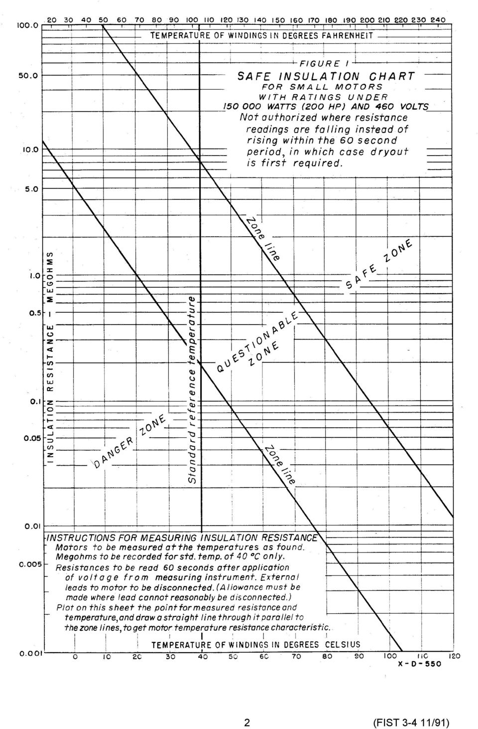
5 is to make the insulation resistance tests with all motor leads disconnected except those which would involve too much trouble of unsoldering and untaping of joints. The chart applies strictly to motors without any leads connected. Where cables to the motors are short, new, or dry, the insulation resistance of these cables which is in parallel with that of the motor winding will usually have only a small effect. The test data should note when leads are included in the measurement. Each measurement, corrected to the standard 40 EC temperature, should be recorded and used as a permanent "bench mark" for future reference. Any large variations from similar motors should be viewed with suspicion. All questionable or low readings should be further investigated by untaping or unbolting the cables not usually disconnected for this test, so as to locate and identify the cause for such low readings. Suitable steps should be taken to eliminate the cause of the low readings. The recommended minimum insulation resistance, Rm, for armature and field windings of motors of larger size and higher voltage than are covered in Figure 1 can be determined by the equation: Where: R m = V t + 1 R m = recommended minimum insulation resistance in megohms at 40 EC of the entire machine winding V t = rated machine terminal to terminal potential in, rms, kilovolts The winding insulation resistance obtained by applying direct potential to the entire winding for I minute must be corrected to 40 EC to be used for comparison with the recommended minimum value of Rm. The insulation resistance of one phase of a three-phase armature winding with the other two phases grounded is approximately twice that of the entire winding. Therefore, the resistance of each phase, when the two phases are tested separately, should be divided by two to obtain a value which, after correction for temperature, may be compared with R m. If guard circuits (a low-impedance bypass around the current meter).are used on the two phases not under test when each phase is tested separately, the observed resistance of each phase should be divided by three to obtain a value which, after correction for temperature, may be compared with R m. Temperature correction factors for insulation resistance are given in FIST Volume PERIODIC TESTS OF INSULATION RESISTANCE.-A standard schedule should be worked out which provides for measuring the insulation resistance of each motor at least once a year. In addition, those motors which have been idle for long periods, especially those in humid atmosphere, should be measured before starting lest the windings burn out when starting up. Tests have shown this to be possible after short exposure to 100 percent relative humidity, whether the motor is fully enclosed or open type. It is preferred that annual resistance measurements be taken at existing room temperature, but it is also satisfactory to measure a warm motor just after shutdown, then correct the resistance to 40 EC. 3. PROTECTION OF WINDINGS FROM DAMPNESS 3.1 General.-Motors subject to excessive moisture can be properly protected by keeping them warm enough during shutdown periods so that condensation does not form or by providing a suitable permanent cover to protect against dripping water or a temporary cover for use during shutdown periods. Which of the above solutions is best depends on local conditions. Prevention of condensation can easily be done by keeping the motor warm, even in air which is continuously saturated to 100 percent relative humidity, with fog showing. Electric heat applied to either the inside or outside warms the entire motor and the air trapped inside the winding is also warmed. When air at 100 percent relative humidity (also called the "dewpoint") is warmed, it reduces the percent humidity. It has been found that the 3

6 motor needs to be warmed only about 5 EC (9 EF) above the surrounding (ambient) air temperature to get it far enough above the "dewpoint," so that moisture does not condense on the frame and winding. Actually, the "dewpoint" temperature at which condensation starts is below ambient temperature but some margin must be provided so that on rapidly rising ambient temperature following a cold period, motor temperature will not lag too far behind the ambient temperature. The relationship of temperatare, dewpoint, and humidity is shown in Figure INTERNAL WARMING METHOD.-Internal warming is accomplished by circulating the amount of current necessary to keep the motor warm through the winding while the motor is shutdown. This method produces heat in the winding conductor where it is most effective in driving out moisture. This can be accomplished by connecting reactors of the proper design across the motor- starter contacts so that when the contacts are open the motor remains energized, but at a very Iow voltage. Transformers with low-voltage secondaries can also be used but would require separate switches to connect and disconnect them as needed. The Internal heating method has been used on only a few of Reclamation's Installations because of the cost of the special reactors or transformers required. 3.3 EXTERNAL WARMING METHOD.-The least expensive and most widely used warming method is the use of electric-strip heaters attached to the motor frame to supply external heat. Where electric-strip heaters are used, they should be mounted in contact with the iron frame near the underside of the motor. The flat-strip-type heaters are preferable as they can be mounted flat against the metal frame and give better transmittal of heat to the iron than the round- cartridge type. The heaters should not be mounted close enough to the motor winding end turns so that the heat can damage the insulation either by direct radiation or by flames from any inflammable material which might be set afire by the heaters. It is important that heaters be selected which run at a low surface temperature so that bearing oil or other inflammable material, which might come in contact with it, will not be ignited. To accomplish this, the heaters should be operated at one-half their rated voltage. That is, use a 240-volt, alternating-current element or two 120-volt, alternating-current elements in series on a 120-volt, alternating-current circuit. This will also insure long life for heaters. The heat provided by strip heaters operating at one-half rated voltage will be one-fourth the rated watt value. Electric heaters should be connected through an auxiliary switch on the motor starter so that they will be "on" when the motor is "off," and vice versa. In using this method, it is necessary to apply only enough heat to maintain the motor frame at 5 EC (9 EF) above ambient temperature to prevent condensation. There is a general tendency to apply too much heat rather than not enough. Approximately 43 watts per 45 kilograms (100 pounds) of motor mass is sufficient to maintain the motor frame 5 EC (9 EF) above ambient temperature in still air. Several small heater units are preferable to one large heater unit. 3.4 MOISTUREPROOF COVERS.-Where electric power is not available or cannot be economically justified to keep motors warm during long shutdown periods, the most practical solution is providing moistureproof covers of plastic or waterproofed fabric. These covers should be bound tightly around the shaft and motor base so as to be as airtight as possible. Some reduction in moisture trouble may be obtained by placing a drying agent such as silica gel in porous bags inside the cover. The silica gel can be reused after drying it out at a temperature of about 110 EC (230 EF) until its mass (weight) has reached the minimum. The use of silica gel will not entirely exclude moisture under severe atmospheric conditions. After a long shutdown period, megohm readings must be taken on the windings of a motor protected in the above manner to determine if the motor insulation must be dried out before it is returned to service. Reduced life of motor windings can be expected where they are subjected to repeated cycles of wetting and 4

7 FIGURE 2 RELATIONSHIP OF AIR TEMPERATURE, DEW POINT AND HUMIDITY, APPROXIMATELY CORRECT FOR ELEVATIONS OF 0 - TO 1524 M (0 - TO 5000 FT) 5

8 drying and the above method of protection is recommended only when the motors cannot be kept warm during shutdown periods ENCAPSULATED AND "B" STAGE INSULATION SYSTEMS.-Thermosetting resin insulation in the form of fully encapsulated insulation systems for small motors up to around 150 kw (200 hp) and "B" stage insulation systems for larger motors up to 9,000 kw (12,000 hp) has been used by Reclamation since the mid 1960's. These insulation systems have proven to be very effective in eliminating problems of moisture absorption. 4. REQUIREMENT FOR MOTOR DRYING 4.1. GENERAL-If a motor winding that does not have a thermosetting resin insulation system has been subjected to excessive moisture or the insulation test shows it to be in the danger zone, it should be dried out before it is placed In service. A low insulation resistance value on a motor with a thermosetting resin (fully encapsulated or "B" stage) insulation system is indicative of a more serious problem (such as a crack in the insulation system) than can be solved by merely drying out the motor, and efforts should be made to determine the cause of the low resistance value. The following paragraphs describe the procedures to follow in drying motor windings DRYING BY INTERNAL HEAT.- Passing current through windings is one of the most effective means of drying motors. If the measured insulation resistance is in the questionable zone of figure 1, the motor can usually be dried by running unloaded with half-rate voltage applied. However, there is always some risk in applying even half-rated voltage and this method is not recommended if one of the following methods can be used. Also this method will take longer as the no-load operating temperature will be rather low. If the insulation resistance is in the danger zone, approximately full-load current can be circulated through the winding with the rotor stationary or removed, using a suitable lowvoltage source, such as a loading transformer or alternating or direct-current arc welder. Voltage must be adjusted to limit the current in the windings to a safe value, usually something less than rated amperes. These internal heating methods apply heat at the winding conductors where it is most effective in driving out the moisture. However, care must be used not to apply too much heat by this method as vapor pressure can be built up within the damp insulation which may rupture it. This danger can be avoided by starting with a low value of current and increasing it gradually until a maximum temperature of 85 EC (185 EF) is observable on the surface of the coils. The motor must be sufficiently open so that moisture can easily escape outside of the enclosing frame. A forced-air draft by electric fan or blower also reduces the time needed for dryout, which may require hours or days as the case may show. The bulb of a rod-shaped thermometer should be attached to the motor winding with putty or a glued felt pad. The current should be reduced or cut off intermittently, if necessary, to prevent excessive temperature so that no scorching will occur DRYING IN OVEN OR BY EXTERNAL HEAT.-Small equipment which can readily be moved may be dried in baking ovens. If an oven is not available, a temporary oven may be constructed around the equipment using insulating board or a tarpaulin cover, etc. Make sure provisions are made for the escape of moisture. Heat may be introduced by means of electric heaters, infrared rays, hot-air furnaces, radiators, and stoves. Use of an open flame is not recommended. An electric fan or other blower should be used to force clean hot air through the motor. It is recommended that the air temperature in the oven not exceed 85 EC (185 EF) when drying class "A" insulation or 105 EC (220 EF) when drying class "B" or higher temperature-rated insulation. These precautions must be observed to avoid permanent damage to insulation SELECTING THE PROPER DRYING TEMPERATURE-The temperature at which the dryout is to be made should be selected according to the condition of the motor winding. If the insulation resistance falls in the 6

9 "questionable" zone, dryout should not be difficult, and a lower drying temperature could be selected, since this will do the work. If resistance is low down in the "danger" zone, a medium drying temperature should be selected. If the motor has been flooded and the motor was quite warm at the time, this is the worst possible condition and nothing but the highest allowable temperature will be found effective. If the motor is badly needed back in service, it may be necessary to take some risk and choose a higher temperature which will dry faster. If the motor is small, more risk could be taken than on a larger motor where the cost of rewinding is high CHECKING PROGRESS OF DRYOUT. Progress of dryout should be watched by taking insulation resistance readings using a low-voltage instrument to avoid puncturing the wet insulation. If previous measurements of the dry insulation resistance are available, they will afford a "benchmark" of the normal insulation to show by comparison when dryout has been completed. This often shortens considerably the drying time and helps to prevent false interpretation of the dryout curves when these curves tend to level off at values below normal due to entrapped moisture or local wet spots. Any sudden downward drop in the resistance readings not accounted for by a rise in temperature indicates that trapped moisture is still present and dryout should continue. Each motor will have its own final top reading; but to be safe, the readings should be as high up in the SAFE ZONE on figure 1 as reasonable possible, although occasionally a motor may fail even in this zone. When starting the dryout, readings of insulation resistance may be omitted while warming up until the drying temperature is reached. Temperature should be held as accurately as possible because even small changes make resistance readings change widely and they must be corrected to the drying temperature selected using Figure 1 for a correction chart. If drying at 90 EC (194 EF), for example, but the temperature drops down to 80 EC (176 EF) with a resistance of 0.04 megohm ( ohms), plot this point on the drawing in pencil and extend a line through it parallel to the zone lines over to the zone lines, over to the 90 EC line, where it crosses at megohm. These corrected points should always be used to plot the dryout curve. The reading should be taken once each hour after reaching the dryout temperature. This time may be increased to 2 or 4 hours when the changes become too slow, provided the temperature does not fluctuate too much. Figure 3 illustrates how the resistances should be plotted against time. No two motors will behave exactly the same, however, and large differences are to be expected. Small motors should dry faster than larger machines. Erratic readings or failure of the insulation resistance to increase normally may indicate an insulation fault or damage requiring repair before energizing the machine. 7

10 8
