PURESTREAM MINI-CUBE. QBS Air Cooled Water Chiller User Manual BY FRIULAIR
|
|
|
- Anissa Murphy
- 4 years ago
- Views:
Transcription


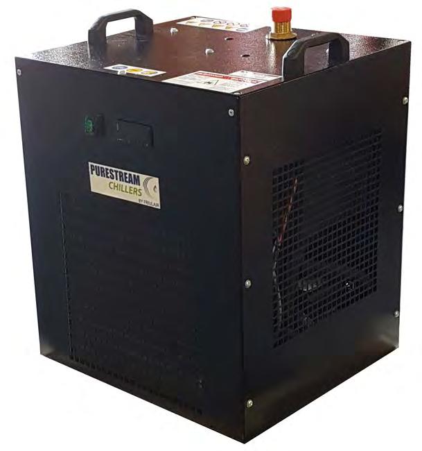

1 PURESTREAM MINI-CUBE BY FRIULAIR QBS Air Cooled Water Chiller User Manual
2 Editions Record Code Revision Edition Changes 7425MUM /2018 Original instructions: ITALIAN EN Translation of the original instructions
3 Dear Customer, Thank you for the trust you have placed in us. Please read this manual carefully to obtain the best performance from our product. In order to avoid incorrect operating conditions and danger for the operators, it is essential that you follow the directions meticulously as well as the current accident-prevention laws in the country of use. Each QBS chiller is rigorously tested before being packed. This verifies that there are no manufacturing defects and that the machine performs correctly the functions for which it was designed. This manual must be kept for future reference and is an integral part of the chiller you have purchased. Due to continuous technical development, we reserve the right to make the necessary modifications without any obligation to give advance notice. Do not hesitate to contact us if you have any problems or need more information. The product identification plate, located on the side of the chiller, contains all essential information about the machine. You will have to give this data to the manufacturer, or reseller, whenever you request information, replacement parts, etc., during the warranty period. Removing or tampering with the identification plate will void the warranty. Warranty conditions: For 12 months from the commissioning date, and no more than 14 months from the shipping date, any parts that were originally defective will be repaired or replaced at no charge. Expenses for transport and travel, room and board for our technicians are excluded. The warranty excludes any liability for direct or indirect damage to persons, animals and/or property that are caused by incorrect use or inadequate maintenance and is exclusively limited to manufacturing defects. The right to service under the warranty is secondary to your faultless observance of the installation, use and maintenance instructions in this manual. The warranty will be voided immediately if the chiller is modified or tampered with, even slightly. When requesting warranty service, you must provide the data on the product's identification plate.
4 SUMMARY 1 Safety Rules Definitions of the symbols used Warnings Proper use of the chiller Instructions for using equipment under pressure conforming to PED Directive 2014/68/EU 3 2 Operation And Main Components Refrigerant circuit Water circuit Fan Condensation control Control of the water temperature Protecting the integrity of the machine QBS units: identification of the main components Spare parts Installation Transport Storage Place of installation Installation spaces Water connections Recommended water system Use of ethylene glycol as a winter anti-freeze Charging the water circuit Electrical connections Preliminary Checks And Start-Up Preliminary checks and preparation for the first start-up Startup Start-up under critical conditions Electronic Controller QBS standard Main functions of the electronic controller buttons and meanings of the icons Turning on and off Controlling water temperature Changing the set point Temperature display as detected by the probes Locking and unlocking the keyboard Compressor operation hours Setting the configuration parameters Autoadaptive Controller QBS with EAA option Main functions of the electronic controller buttons and meanings of the icons Turning on and off Controlling water temperature Standard setting Changing the set point Showing the temperature read by probe 1 (ambient temperature) Showing the temperature read by probe 2 (outlet water temperature) Locking/Unlocking the keyboard Alarms Setting configuration parameters Table of standard parameters configuration... 19
5 6.11 Alternative method of temperature regulation Calibration of the safety devices and type of rearm Rearming the high-pressure pressure switch Operating Limits SEPR - SEASONAL ENERGY PERFORMANCE RATIO ACCORDING TO COMMISSION REGULATION (EU) 2016/ Maintenance, Inspections And Periodic Checks Troubleshooting Dismantling The Chiller Water Diagrams Refrigerant Diagrams Dimensional Drawings... 29
6 SAFETY RULES DEFINITIONS OF THE SYMBOLS USED Read this use and maintenance manual carefully before performing any repairs on the chiller. Warnings of a general character; risk of danger or possibility of damaging the machine, pay particular attention to the phrase following this symbol. Risk of electrical danger; the phrase highlights conditions that could be fatal. Follow the instructions provided meticulously. Risk of danger; component or system under pressure. Risk of danger; component or system that can reach high temperatures during operation. Risk of danger; it is absolutely forbidden to use water to extinguish fires near or on the chiller. Risk of danger; it is absolutely forbidden to operate the machine with the panel open. Service that can be performed by the machine s operator, if qualified (1). Water input connection point. Water output connection point. Dispose of each type of material in accordance with the requirements of the country of use. NOTE Phrases to be emphasized that do not contain safety rules. 1
7 This chiller has been carefully designed and constructed to be environmentally friendly: Refrigerants without CFC; Expanded foam insulation without CFC; Energy-saving techniques; Reduced noise; The chiller and its packing materials are recyclable. In order not to hinder our efforts, the user is required to obey the simple ecological warnings indicated by this symbol. (1) These are persons with the experience, technical preparation and knowledge of standards and regulations who are qualified to perform the necessary actions and able to recognize and avoid possible dangers while handling, installing, using and maintaining the machine. 1.2 WARNINGS Only qualified persons may use and maintain electrically-powered equipment. Before commencing maintenance operations ensure no parts of the machine are live and it cannot be re-connected to the electrical power supply. The QBS chillers contain R134A refrigerant. Operations on the cooling circuit must only be performed by specialist personnel with suitable equipment. Any modifications to the machine or related operating parameters not previously verified and authorized by the Manufacturer may be hazardous and will invalidate the guarantee. Do not use water to extinguish fires near or on the chiller. 1.3 PROPER USE OF THE CHILLER QBS units are packaged air-cooled water chillers. They are intended for use in industrial process or air-conditioning systems requiring chilled water. Any other use is considered as incorrect. The manufacturer is not liable for damage resulting from inappropriate use; in all cases, the user is liable for any resulting hazards. Proper use requires conforming to the installation conditions and limits of operation (see sections 3.5 and 7). In particular: Power voltage and frequency; Pressure, temperature of incoming water; Water flow rate; Surrounding temperature. The chiller has been tested and completely assembled. The user must only make the connections to other systems, as described in the chapters that follow. 2
8 1.4 INSTRUCTIONS FOR USING EQUIPMENT UNDER PRESSURE CONFORMING TO PED DIRECTIVE 2014/68/EU The proper use of equipment under pressure is an essential prerequisite for ensuring safety. To this end, the user must proceed as follows: Use the equipment properly within the temperature limits shown in the operating limits stated on the manufacturer s name/data plate; Do not solder on the exchangers or refrigerant fluid pipes; Do not install the equipment in insufficiently ventilated rooms, areas exposed to sources of heat or near inflammable substances; During operation, the equipment must not be subjected to vibrations that could cause fatigue failures; Keep the documentation attached to the equipment (user manual, declaration of conformity, etc.) for future reference; The maximum working pressure stated on the manufacturer s data plate must not be exceeded. Prior to use, the user must fit safety/pressure relief devices. 3
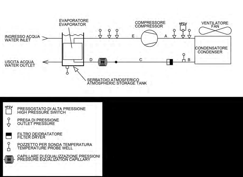
9 OPERATION AND MAIN COMPONENTS REFRIGERANT CIRCUIT QBS chillers use a vapour-compression cycle in a refrigerant circuit that essentially consists of the following components: evaporator, compressor, condenser, lamination device (capillary tube). Evaporator: heat exchanger (tube and fins) to enable heat exchange between the water and the refrigerant liquid without them coming into contact with each other. The water is cooled when it passes through the evaporator. Compressor: compresses the steam from the evaporator to send it to the condenser at a higher pressure. Condenser: tube and fins exchanger to enable heat exchange between the refrigerant and the air; it creates refrigerant gas condensation transferring the gas refrigerant condensation heat to the air (which flows externally); high pressure refrigerant liquid is thus produced. Lamination device: reduces the pressure of the liquid refrigerant coming from the condenser, which is then sent to the evaporator. Thanks to these components, the vapour-compression cycle works as follows: the refrigerant liquid evaporates in the evaporator, chilling the water; the refrigerant vapours are then aspirated from the compressor, which compresses them and sends them to the condenser under high pressure; here, thanks to a flow of forced air from the fans, the high-pressure refrigerant gas is cooled, making it condensed and undercooled. The flow of refrigerant liquid then passes through the lamination valve (thermostatic expansion valve), which drastically reduces its pressure: the refrigerant liquid returns to the evaporator at a reduced pressure where it again evaporates, taking heat from the water. The refrigerant circuit also includes a water pump, which ensures the flow of water to be chilled by evaporation, and the fan which ensures the condenser is cooled. 2.2 WATER CIRCUIT The water circuit mainly consists of a pump, evaporator, tank. The water flows into the evaporator first where it is cooled, then into the tank, and is then suctioned by the pump which sends it to the system (see Water diagram section 11). All QBS units have an open circuit with a tank at atmospheric pressure. See chapter 11 Water diagram. 2.3 FAN The fan forces air through the condenser fins to remove the refrigerant gas condensation heat, therefore limiting the pressure inside the condenser. QBS chillers are equipped with axial fans and have internal heat protection for the motor windings. 2.4 CONDENSATION CONTROL When the ambient air temperature decreases, air flow cooling capacity increases slightly, causing a reduction in pressure inside the condenser; to limit this decrease in condensation pressure from falling below acceptable limits for good cooling circuit operation the fan stops temporarily. 4
10 2.5 CONTROL OF THE WATER TEMPERATURE The purpose of the chiller is to maintain the temperature of the water produced within a desired interval as the load on the system varies; this is handled by an electronic controller and a temperature probe that turn the compressors on and off appropriately (see also sections 5.3). 2.6 PROTECTING THE INTEGRITY OF THE MACHINE In addition to controlling the temperature, the electronic controller uses pressure switches, thermostats and timers to prevent and handle situations that could compromise the integrity of the machine (also see Chapter 6 Safety Devices). 2.7 QBS UNITS: IDENTIFICATION OF THE MAIN COMPONENTS 04 High pressure switch 06 Compressor 08 Condenser 9.1 Fan 10 Refrigerant filter 11 Capillary tube 12 Temperature probe 17 Electronic controller 18 Evaporetor 22 Disconnector switch 61 Power input 90 Pump 91 Tank 93 Level indicator 95 Water input 96 Water output 97 Drain 99 Pressure plug 5
11 2.8 SPARE PARTS Spare parts list is printed on a dedicated sticker applied inside the chiller. On this sticker each spare part is identified with its ID Number and related Spare Part Number. Here below the cross reference table between ID Number and exploded drawings Ref. With their description and quantity installed inside chillers. NOTE To order the suggested spare parts or any other part, it is necessary to quote the data reported on the identification plate. 6

12 INSTALLATION TRANSPORT The units are supplied packed in a cardboard box on a wooden pallet. After checking that the packing is undamaged, position the unit near the installation site and unpack it. Always keep the chiller vertical: turning it upside down can irreparably damage several parts of the unit. Handle with care. Violent falls can cause irreparable damage. The centre of the machine is approximately its centre of gravity. In any case, when handling the machine with a forklift truck or pallet jack, always check its stability before lifting. 3.2 STORAGE Protect the machine from bad weather, even if packed. Always keep the chiller vertical, even when in storage. Turning it upside down can irreparably damage several parts of the unit. If not used, the chiller can be stored packed in an enclosed place, free of dust, with a maximum temperature of 50 C//122 F and specific humidity of not higher than 90%. The packing material is recyclable. Dispose of each type of material in accordance with the requirements in the country of use. 3.3 PLACE OF INSTALLATION Warning! The QBS models are suitable for indoor installation only. To determine the best place to install the unit, it is important to consider the following aspects: The dimensions and source of the water pipes; The location of the power supply; 7
; Provide access for maintenance or repair (see paragraph 3.")
13 The solidity of the support surface; Avoid any obstacles to the flow of the fan which could cause the recirculation of air to the condenser; Avoid the possible reflection of sound waves: (do not install in narrow or tight spaces); Provide access for maintenance or repair (see paragraph Installation spaces); Average air temperature in the chosen installation area (see Section 7 Operating limits). Attention! If the machine is installed outside, it could find itself at a temperature lower than 0 C//32 F, when stopped; the formation of ice could damage the evaporator. If you do not intend to drain the machine during the winter, you must add anti-freeze to the water circuit (see paragraph Use of ethylene glycol as a winter anti-freeze) Installation spaces To ensure the good functioning of the unit and access for maintenance, you must respect the minimum installation space shown in the figure in this paragraph. The exit of air from the fan must not be obstructed. In any case, avoid all situations in which hot air can circulate between the output of the fan and the intake of the machine. Contact our office to verify feasibility in all cases where one of the preceding conditions cannot be met. 800mm/31inches on each side QBS WATER CONNECTIONS Connect the machine to the water pipes following the instructions located near its water fittings (see figures). The installation of outlet and inlet taps on the machine is recommended, which will enable machine maintenance without emptying the entire system, and emptying of the machine only during winter downtime. Important! Install the mechanical water filter on its input: scum and impurities can seriously damage the evaporator. 8

14 We recommend an extraordinary cleaning of the mechanical water filter after the machine has been running for the first week (also see Chapter 8 Maintenance, inspections and periodic checks). Warning! No naked flames should be used during water connection operations, in the vicinity of or inside the unit. NOTE It is a good rule that the diameters of the arriving and departing pipes be not less than the water fittings. QBS Hz 60 Hz Diameter of the in/out water fittings 3/8 GAS FM 3/8 NPT FF Recommended water system QBS units come as standard with a tank at atmospheric pressure, pump and bypass; it is advisable to also provide the water circuit with: A mechanical filter for water in the machine inlet pipes, with mesh no greater than 1mm; Machine inlet and outlet taps; Inlet and outlet pressure gauges and thermometers for water from the machine, to control its operation. Diagram of recommended water circuit for QBS models 9

15 Key 1 Tap 4 Thermometer 2 Mechanical filter 5 System/unit discharge 3 Pressure gauge Use of ethylene glycol as a winter anti-freeze Instead of emptying the system in the winter, you can charge the system with a mixture of water and a suitable percentage of ethylene glycol, chosen as a function of the lowest expected temperature of the outside air. Percentages of ethylene glycol recommended as a function of the expected temperature of the outside air Outside air temperature [ C] Outside air temperature [ F] Percentage of ethylene glycol [%] Attention! Maximum concentration of ethylene glycol allowed: 20%. For glycol concentrations higher than 20%, contact our company's sales offices to make sure that the mechanical seal and the pump motor are suitable for the type and concentration of fluid loaded in the hydraulic system Charging the water circuit Check that the drain taps are turned off; Open the system interception devices; Attention! Make sure that the tube that draws the inlet water to the pump is almost always fluid-filled. It is also recommend, at least in the very early re-start phase, to close the liquid outlet port of the chiller to increase the pump's prevalence. This will avoid premature failure of the impeller and will extend the life of mechanical seal. Also, the engine will not overheat. Feed the water from the filling inlet above the machine until the water reaches the required level (near the transparent level indicator see diagram). When the pump starts check the level again and top up if necessary; Check for any leaks by examining the circuit. Water level indicator 10
16 3.5 ELECTRICAL CONNECTIONS The machine must be connected to the electricity following the electrical diagram and conforming to the current laws and regulations in the place of installation. The voltage, frequency and number of phases must conform to the data shown on the machine's identification plate; The power supply voltage must not vary by more than ±10% from its nominal value; The frequency must not vary by more than ±1% from its nominal value (±2% for brief periods); The imbalance between power phases must be <2%; Upstream from the electrical panel, install a differential switch (IDn=0.03A) (main power switch) and slow-blow fuses with the specifications shown on the electrical diagram; Use wires of the section shown on the electrical diagram and in the following table. Attention! Never change the internal electrical connections, as the warranty will be immediately voided. Important! Screw the wires solidly to the terminal strip of the cut-off switch and lock the wire with a cable-gland. Important! Make the cable entering the machine enters the cable-gland from below: this prevents rain from dripping inside the machine. Important! The earth connection is mandatory: connect the earth wire to the terminal provided in the electrical panel. The ground wire must be longer than the other wires so that it will be the last one to be pulled if the device holding the cable loosens. 11
17 PRELIMINARY CHECKS AND START-UP PRELIMINARY CHECKS AND PREPARATION FOR THE FIRST START-UP Before starting up the unit, it is a good idea to do the following: Check that the water shut-off valves are open; Verify the regular water level in the tank; Attention! Make sure that the tube that draws the inlet water to the pump is almost always fluid-filled. It is also recommend, at least in the very early re-start phase, to close the liquid outlet port of the chiller to increase the pump's prevalence. This will avoid premature failure of the impeller and will extend the life of mechanical seal. Also, the engine will not overheat. Check that the surrounding temperature is in the range for the machine to function (see Chapter 7 Operating Limits); Check the cut-off switch on the machine switchboard is open; Check that the mains voltage matches the voltage on the machine's identification plate with a tolerance of ±10%; Close the main power supply switch; Close the cut-off switch on the machine's electrical panel. 4.2 STARTUP Connect the device power supply. Touch the for 4 seconds. The led will flash and turn off, the chiller will switch on. The controller will display the temperature of the water inside the tank - if it is higher than the set value the compressor will start up. To disable, touch the for 4 seconds. The led will flash and turn on, the chiller will switch off. 4.3 START-UP UNDER CRITICAL CONDITIONS The consequence of starting up under critical conditions could be the intervention of the high-pressure pressure switch (to rearm the high-pressure pressure switch, see paragraph 6.2 Rearming the highpressure pressure switch). To overcome this problem, you will have to reduce the thermal load on the machine by shutting off some of the uses or, if this is not possible, by reducing the flow of water into the evaporator: partially close the output tap from the chiller and restart the machine. Operate the chiller under these conditions until the water temperature gradually returns within operating limits; then, you can turn on the tap completely. 12
; Enables compressor activation and deactivation (standby); Controls on/off compressor operation depending on the temperature of the water measured with the set point and upper")
18 ELECTRONIC CONTROLLER QBS STANDARD 5 The QBS electronic controller: Displays the temperature of the water exiting the water chiller; Enables the required temperature of the chilled water to be set (set point); Enables compressor activation and deactivation (standby); Controls on/off compressor operation depending on the temperature of the water measured with the set point and upper differential (3 C//3K//5,4 F); Guarantees minimum compressor on/off times to maintain its integrity; Signals any faults in the temperature probe. 5.1 MAIN FUNCTIONS OF THE ELECTRONIC CONTROLLER BUTTONS AND MEANINGS OF THE ICONS Button Function On/off button Exit procedure Setting setpoint Access the menu Down key Up key Display/Led Function Indicates the state of compressor: On: compressor ON Off: compressor OFF Flashing: setting setpoint mode or compressor protection Indicates the state of the fans: On: fan ON Off: fan OFF Flashing: fan stopping Auxliary led Energy saving on Celsius unit Fahrenheit unit Indicates the state of the chiller: On: chiller OFF Off: chiller ON 13
19 The display shows alarms like in the following table. Sign Description Type of rearm Multifunction input alarm ia Manual Pressure switch alarm Pr1 Probe AI1 failure Automatic Pr2 Probe AI2 failure Automatic AL Minimum temperature AI1 probe - Antifreeze Automatic AH Maximum temperature AI1 probe Automatic COH Superheated condenser Automatic CSd Blocked condenser Automatic 5.2 TURNING ON AND OFF Connect the device power supply. Touch the for 4 seconds. The led will flash and turn off, the chiller will switch on. To disable, touch the for 4 seconds. The led will flash and turn on, the chiller will switch off. 5.3 CONTROLLING WATER TEMPERATURE The QBS s electronic controller regulates the outlet water temperature on the basis of a set point value and an upper differential of 3 C//3K//5,4 F according to the following diagram: 5.4 CHANGING THE SET POINT Touch the : the flashing led indicates that the setpoint can be changed. Use and keys within 15 seconds to change the temperature setpoint. Touch key or do not operate for 15 seconds to confirm the value. Otherwise, touch key, but any changes will not be saved. The led will switch off and the device will exit the procedure. 5.5 TEMPERATURE DISPLAY AS DETECTED BY THE PROBES Make sure that the keyboard is not locked and that no procedure is in progress; Touch the key for 4 seconds: the display will show the first label available; Touch the or key to select a label Pb1/ Pb2; Touch the key to display the corresponding temperature; To exit the procedure, touch key or do not operate for 60 seconds; Touch the key. 14
20 5.6 LOCKING AND UNLOCKING THE KEYBOARD To lock the keyboard proceed as follow: Make sure that the keyboard is not locked and that no procedure is in progress; Do not operate for 60 seconds: the display will show the message Loc for 1 second and the keyboard shall lock automatically. To unlock the keyboard: Touch a key for 1 second: the display will show the message UnL for 1 second. 5.7 COMPRESSOR OPERATION HOURS To shoe the compressor operation hours: Make sure the keyboard is not locked and that no procedure is in progress; Touch the key for 4 seconds: the display will show the first label available; Touch the or key to select the label CH; Touch the key to display the corresponding compressor s running hours. To cancel the compressor operation hours: Make sure the keyboard is not locked and that no procedure is in progress; Touch the key for 4 seconds: the display will show the first label available; Touch the or key to select the label rch; Touch the key; Touch the or key within 15 seconds to set a password0f1 ; Touch the key or do not operate for 15 seconds: the display will show a flashing for 4 seconds, after which the device will exit the procedure. 5.8 SETTING THE CONFIGURATION PARAMETERS To access the procedure: Make sure no procedure is in progress; Touch the key for 4 seconds: the display will show PA ; Touch the key; Touch the or key within 15 seconds to set a password 1F2 ; Touch the key or do not operate for 15 seconds: the display will show SP. To select a parameter: Touch the or key; To set a parameter: Touch the key; Touch the or key within 15 seconds to set the value as desired; Touch the key or do not operate for 15 seconds. To exit the procedure: Touch the saved). key for 4 seconds or do not operate for 60 seconds (any changes will be 1 Contact our company. 2 Contact our company. 15

21 After setting the parameter, suspend power supply flow to the device. AUTOADAPTIVE CONTROLLER QBS WITH EAA OPTION 6 The QBS electronic controller: Displays the temperature of the water exiting the water cooler; Enables the required temperature of the chilled water to be set (set point); Signals any faults in the temperature probe. 6.1 MAIN FUNCTIONS OF THE ELECTRONIC CONTROLLER BUTTONS AND MEANINGS OF THE ICONS Button Function Setting setpoint Down key Access the menu Up key Display/Led Function Indicates the state of the fans: On: fan ON Off: fan OFF Flashing: fan stopping Celsius unit Fahrenheit unit Indicates the presence of alarms 6.2 TURNING ON AND OFF Connect the device power supply. To turn on the instrument you have to supply it by the cut-off switch. To turn it off it is enough to cut off the power supply by closing the cut-off switch. The display will shows the outlet water temperature. 16
22 6.3 CONTROLLING WATER TEMPERATURE STANDARD SETTING The QBS s electronic controller regulates the outlet water temperature in function of the ambient temperature. The working setpoint will be relative to the temperature read by probe or temperature read by probe 1 working setpoint (without sign). 6.4 CHANGING THE SET POINT Make sure the keyboard is not locked and no procedure is running. To gain access the procedure: Press and 4 seconds and the display will show PA ; Press ; Press or in 15 seconds to set the password2f3 ; Press or do not operate 15 seconds; Press and 4 seconds and the display will show SP, the first available parameter. Press or to scroll the parameter list until you reach r0 ; To select the parameter, press and use or in 15 seconds to modify the setting value; Press to confirm the value or do not operate 15 seconds. 6.5 SHOWING THE TEMPERATURE READ BY PROBE 1 (AMBIENT TEMPERATURE) Make sure the keyboard is not locked and no procedure is running. Press 2 seconds: the dispaly will show the first available label; Press or to select Pb1 ; Press to show the setting value. 6.6 SHOWING THE TEMPERATURE READ BY PROBE 2 (OUTLET WATER TEMPERATURE) Make sure the keyboard is not locked and no procedure is running. Press 2 seconds: the dispaly will show the first available label; Press or to select Pb2 ; Press to show the setting value. 3 Contact our company. 17
23 6.7 LOCKING/UNLOCKING THE KEYBOARD Make sure the keyboard is not locked and no procedure is running. Press and 2 seconds: the display will show Loc 1 second. If the keyboard is locked, you will not be allowed to: Show the temperature read by probe 1 and probe 2; Modify the working setpoint. This operations provoke the visualization of the label Loc 1 second. To unlock the keyboard: Press and 2 seconds: the display will show UnL 1 second. 6.8 ALARMS The display will show the following code of alarm. Code Description Type of rearm Minimum temperature probe 1 AL1 (ambient temperature) Automatic Maximum temperature probe 2 AL2 (outlet water temperature) Automatic Pr1 Probe 1 error Automatic Pr2 Probe 2 error Automatic Loc Keyboard and/or setpoint are locked The quantity to show is not available SETTING CONFIGURATION PARAMETERS To gain access the procedure: Press and 4 seconds and the display will show PA ; Press ; Press or in 15 seconds to set the password 3F4 ; Press or do not operate 15 seconds; Press and 4 seconds and the display will show SP, the first available parameter. Press or to scroll the parameter list; To select a parameter, press and use or in 15 seconds to modify the setting value; Press to confirm the value or do not operate 15 seconds. 4 Contact our company. 18
24 6.10 TABLE OF STANDARD PARAMETERS CONFIGURATION Below there is a table of most important parameters and their factory setting. To modify the parameter contact our company. Parameter Function Factory setting SP Working setpoint 0 C//32 F r0 Working setpoint differential 5K r1 Minimum working setpoint 0 C//32 F r2 Maximum working setpoint 25 C//77 F r6 Type of working setpoint: Absolute setpoint r6=0 1 Relative setpoint r6=1: temp. read by probe 1 working setpoint r7 Forced off of compressors 4 C//39,2 F Differential of parameter r7 r8 [At r7+r8 value the compressor could be switched on] 2K A1 Temperature the alarm of low temperature is activated AL1 4 C//39,2 F A4 Temperature the alarm of high temperature is activated AL2 50 C//122 F Differential of parameter A1 A10 [At A1+A10 value the alarm AL1 will be deactiveted] 2K Differential of parameter A4 A11 [At A4-A11 value the alarm AL2 will be deactiveted] 5K 6.11 ALTERNATIVE METHOD OF TEMPERATURE REGULATION The electronic controller allows to regulate the outlet working temperature with an absolute logic in function of the temperature read by probe 1. In that way, the SP value is the absolute regulation setpoint like in the following image. To set this kind of working mode, please set the following values in that way (see paraghaph 5.9 Setting configuration parameters). Parameter Function Suggested value r1 Minimum working setpoint 6 C//42,8 F r6 Type of working setpoint: Absolute setpoint r6=0 Relative setpoint r6=1: temp. read by probe 1 working setpoint 0 19
25 Safety Devices QBS chillers have a series of safety devices that limit the machine's temperature and pressure values to ensure that it operates within the expected limits and to avoid dangerous situations. Here is a list of dangerous situations, including the relative safety device and its location. Dangerous situation Safety device Location High condensation pressure High-pressure switch Compressor output pipe Low water temperature Anti-freeze thermostat Water exit from the evaporator Frequent compressor start-ups Anti-circulation timer Electronic controller Low water level in the tank Water-level sensor Tank Legend: n.a. not available Opt.: optional When they reach their calibration value, most of the security devices trigger an alarm managed by the electronic controller. For some safety devices, once the cause of the alarm times out, the machine resumes operation automatically as soon as the reset value is reached. Others must be manually reset to restart the machine. The following paragraph lists the characteristics of each safety device. 6.1 CALIBRATION OF THE SAFETY DEVICES AND TYPE OF REARM Safety device Intervention value Reset value Type of rearm High-pressure gauge 30 barg//435 psi 23 barg//334 psi Manual Anti-freeze thermostat 4 C//39,2 F 6 C//42,8 F Semiautom. Water-level sensor Semiautom. Anti-circulation timer* 5 min * This is a function of the electronic controller that prevents the same compressor from stopping and starting too frequently: at least 5 minutes must elapse between one compressor s power up and the next. 20

26 6.2 REARMING THE HIGH-PRESSURE PRESSURE SWITCH The intervention of the high-pressure pressure switch is the only case in which, in addition to manually rearming the electronic controller, it is also necessary to reset the pressure switch itself. The high-pressure pressure switch is located in the compressor compartment on the uninsulated copper pipe that goes from the compressors to the condensation coil; there is a manual-reset button on top of it. Warning! The upper part of the compressor casing and discharge pipe are at a high temperature. Be especially careful when working in their vicinity. This can only be rearmed when the pressure in the circuit has fallen below the reset value (see table Calibration of the safety devices and type of rearm in paragraph 6.1). For this reason, when dealing with an intervention of the high-pressure switch, it is necessary to: A) Identify the cause of the rise in pressure (fan not working, condensation coil dirty or obstructed, obstacles to the flow of exiting air, operating temperature outside operating limits, etc. (also see Chapter 9 Troubleshooting) and remove the cause, if possible; B) Wait until the high-pressure manometer falls below the reset value (see the table, Calibration of the safety devices and type of rearm in paragraph 6.1); C) Rearm the pressure switch by pressing the red button: if you do not hear a click, it is not rearmed; D) Then rearm the electronic controller. High pressure switch Attention! The high-pressure gauge stops the compressor while it keeps the condenser fan running to lower the pressure in the condenser. 21
 2016/2281 Only for units at 50Hz power supply.")
27 OPERATING LIMITS 7 The graphs show the limits for continuous operation of the QBS units, in relation to the temperature of the water exiting the machine, and the temperature of the external air. QBS SEPR - SEASONAL ENERGY PERFORMANCE RATIO ACCORDING TO COMMISSION REGULATION (EU) 2016/2281 Only for units at 50Hz power supply. 230V/1Ph/50Hz Model QBS SEPR 4,16 4,37 22
28 MAINTENANCE, INSPECTIONS AND PERIODIC CHECKS 9 To keep the machine running properly and providing the guaranteed performance required, it is necessary to make some periodic checks. Operation Frequency Execution Check that the temperature of the water produced is in the required interval Daily Check tank water level using level indicator see section Daily Check for the presence of any alarm signals Daily User Check the functioning of the fans Monthly Check that the temperature of the air is compatible with the operating limits of the machine Monthly Clean the condensing coil with a jet of compressed air Annual (1) Clean the water filter Monthly(2) Check that the subcooling and superheating values are, Every 6 months respectively between 3 5K//5,4 9 F and 5 7K//9 12,6 F Specialized Check for traces of oil on the pipes of the refrigerant circuit Every 6 months personnel (symptom of refrigerant leaks) Check the tightness of the electrical terminals both inside the electrical panel and on the terminal strips of the compressors Yearly Check the contacts of the contactors; if they show signs of deterioration, replace them Yearly Check that the current absorbed by the machine is within the values on the identification plate Every 6 months (1) It may be necessary to carry this out more frequently in the case of particularly dirty environments. (2) We recommend an extraordinary cleaning of the filter after the machine has been operating for the first week. (3) It is not necessary to do this if the system has been charged with an anti-freeze solution (water and a suitable percentage of glycol) (see paragraph Use of ethylene glycol as a winter anti-freeze). Attention! Before carrying out any maintenance on the unit or accessing internal parts, make sure you have cut-off the electricity. Attention! The upper part of the compressor housing and the output pipe are hot. Be especially careful when working near them. 23
29 TROUBLESHOOTING 10 Cause Alarm or symptom Solution Execution 1. The unit does not start Contacts of the main differential switch are open Electronic controller off Close the contacts User Unit's electrical panel cut-off switch is open Electronic controller off Close the contacts User Compressor timer active No consent from the service thermostat No consent from the antifreeze thermostat Service and anti-freeze probe defective The compressor icon on the display of the electronic controller is flashing System water at temperature (see display) AL AL Wait (5 mins at the most) Apply a thermal load to the machine or lower the set point Reset a temperature of the water (setpoint) compatible with the calibration of the antifreeze thermostat Check contacts and replace, if necessary User User User Specialized personnel Water temperature probes defective Pr1/Pr2 Check contacts and replace, if necessary Specialized personnel Intervention of the main differential switch Electronic controller off Look for current leakage inside the machine Specialized personnel 2. The compressor does not start Intervention of the thermal protection inside the compressor Contactor of the compressor off The contactor of the compressor is on but the compressor is stopped The compressor icon is on but the compressor is stopped 3. The water pump does not make pressure and flow The suction pipe of the pump is full of air or the pressure drops on the hydraulic circuit are too high The water pump does not work properly Wait for cooling: check that the compressor is working under normal conditions. Check for insufficient refrigerant in the circuit (see point 6). Check the voltage at the coil of the contactos of the compressor and the continuity of the coil itself Make sure that the tube that draws the inlet water to the pump is almost always fluidfilled. It is also recommend, at least in the very early restart phase, to close the liquid outlet port of the chiller to increase the pump's prevalence (see paragraph Charging the water circuit) Specialized personnel Specialized personnel Specialized personnel 24
30 Cause Alarm or symptom Solution Execution 4. Intervention of the high pressure pressure switch Condenser obstructed or insufficient air flow-capacity The unit has operated outside its operating limits (such as air or water too hot) Fan not working ia See point 4 Excessive refrigerant charge ia ia High subcooling (greater than 10K//18 F) Remove dirt from the condenser and any obstacles to the flow of air. Wait for the pressure to drop below the reset value, then rearm the high-pressure pressure switch by pressing the button on top of it (see figure in paragraph 6.2). If possible, restore conditions that are compatible with the operating limits. Reset the high pressure switch (paragraph 6.2). Drain excess refrigerant User User Specialized personnel Presence of air or incondensable gas in the refrigerant circuit Refrigerant filter clogged or thermostatic valve stuck Presence of bubbles on the flow peep hole, also with subcooling values greater than 5K//9 F Pipe downstream from the component covered with frost Drain the circuit, create vacuum and recharge Check and replace Specialized personnel Specialized personnel 5. Fan doesn't start Very low outside air temperatures Fan icon off. and consequent intervention of the Condensation condensation control pressure normal 6. The unit is working without ever stopping Excessive thermal load No refrigerant See point 6 7. Compressor intake pipe covered with frost No refrigerant High overheating, low undercooling and high output temperature of the compressor. Traces of oil on the refrigerant circuit. The machine can working anyway Reduce the thermal load. Reduce the temperature of the incoming water and/or the flow-capacity of the exit tap of the unit a little. Check the chiller circuit with a leak detector. Repair any ruptures and recharge the circuit. 8. The unit stops and starts repeatedly; water temperature changes suddenly Insufficient water flow rate Check water flow rate. Open the system tap fully. If possible reduce system feed leaks. If possible add a pump in series with suitable head. User Specialized personnel Specialized personnel 25
31 DISMANTLING THE CHILLER 11 If the chiller is being dismantled, you must separate it into parts of homogeneous material. The following table lists the main materials of the various components of the machine. Part Refrigerant fluid Panelling and supports Chiller compressor Evaporator Condenser Pipes Fan Valves Insulation Pump Tank Electrical wires Electrical parts Material R134A, Oil Carbon steel, epoxy paint Steel, Copper, Aluminium, Oil Copper Aluminium, Carbon Steel, Copper Copper Aluminium, Copper, Steel Steel, Bronze Synthetic rubber without CFC, EPS, Polyurethane Steel, Copper Stainless steel Copper, PVC PVC, Copper, Bronze We recommend that you follow current safety norms for the disposal of each single material. The refrigerant contains particles of lubrication oil from the chiller compressor. Dispose of refrigerant properly. Remove it from the chiller with suitable tools and deliver it to authorized collection centres that will treat it and make it reusable. 26
32 WATER DIAGRAMS 12 QBS

33 REFRIGERANT DIAGRAMS 13 QBS
34 DIMENSIONAL DRAWINGS QBS Hz QBS Hz 29


35 COOLING SOLUTIONS 3770B Laird Road, Mississauga ON. L5L 0A7 Tel: Fax:
CW-5000/ 5200,1'8675,$/ &+,//(5 86(5 0$18$/
 CW-5000/ 5200 Contents Cautions ---------------------------------------------------------------- 3 Parts introduction --------------------------------------------------- 4 Installation ------------------------------------------------------------
Oil and Coolant Circulating Heating System. Model - OCSM
 Oil and Coolant Circulating Heating System Model - OCSM Installation & Operation Manual 216280-000 REV 2 Identifying Your System The HOTSTART heating system is designed to heat fluids for use in marine
MAINTENANCE INSTRUCTIONS. Thermia Robust heat pump
 MAINTENANCE INSTRUCTIONS Thermia Robust heat pump 9 6 8 0-5 4 7 4 5 0 0 1 R e v. 3 Table of contents 1 Important information.................. 2 1.1 Product description....................... 2 1.2 General................................
SWIMMING POOL HEAT PUMP
 SWIMMING POOL HEAT PUMP Installation & User Manual Model HP40B HP50B HP65B Hayward Pool Products Canada, Inc. T: 1-888-238-7665 www.haywardpool.ca CONTENT I. Application 4 II. Features 4 III. Technical
CDS TROUBLESHOOTING SECTION I. VACUUM. 1.0. Weak vacuum at wand. Gauge reads normal (10hg to 14hg)
") CDS TROUBLESHOOTING SECTION I. VACUUM 1.0. Weak vacuum at wand. Gauge reads normal (10hg to 14hg) 1.1. Clogged hoses or wand tube. Disconnect hoses and carefully check for an obstruction. 1.2. Excessive
CDS TROUBLESHOOTING SECTION I. VACUUM 1.0. Weak vacuum at wand. Gauge reads normal (10hg to 14hg) 1.1. Clogged hoses or wand tube. Disconnect hoses and carefully check for an obstruction. 1.2. Excessive
ECOCIAT. Domestic hot water heat recovery unit
 Heat recovery unit Domestic hot water High energy efficiency with R410A Compact and quiet Scroll compressors Brazed-plate heat exchangers Heating Heat recovery ENVIRONMENTALLY HFC R410A PROTECTION DE FRIENDLY
LOBOY 16 AIR CONDITIONERS
 INSTRUCTION MANUAL FOR: LOBOY 16 AIR CONDITIONERS McLean Midwest Corp. dba: McLean Cooling Technology 11611 Business Park Blvd. N Champlin, MN 55316 Tel: 763-323-8200 Fax: 763-576-3200 www.mcleancoolingtech.com
Art.S001-S002 SOLAR MODULE WITH DELIVERY AND RETURN CONNECTIONS
 Art.S001-S002 SOLAR MODULE WITH DELIVERY AND RETURN CONNECTIONS Technical Information sheet 0001/07/Rev01 ENG FUNCTION Series S001 and S002 circulation units are applied to the primary circuit of solar
Heat Pump Water Heater IOM Manual
 Heat Pump Water Heater IOM Manual Installation Operation & Maintenance This manual is intended as an aid to qualified service personnel for proper installation, operation and maintenance of the heat pump
USER S MANUAL HSC-24A
 AIRREX AIR CONDITIONER USER S MANUAL HSC-24A Thank you for purchasing an AIRREX AIR CONDITIONER. BEFORE operation please read this user s manual carefully. Keep this manual readily available. It is ESSENTIAL
Use and Care Manual. Model CPA12KH AIR CONDITIONER
 Use and Care Manual Model CPA12KH AIR CONDITIONER Introduction Thank you for choosing this air conditioner to provide you and your family with all of the "Home Comfort" requirements for your home, cottage
ENGLISH INSTRUCTION & INSTALLATION MANUAL DUCTLESS MINI SPLIT AIR CONDITIONING SYSTEMS
 ENGLISH INSTRUCTION & INSTALLATION MANUAL DUCTLESS MINI SPLIT AIR CONDITIONING SYSTEMS Céliera Corporation. All rights reserved. Unauthorized duplication, reproduction prohibited. CONTENTS SAFETY PRECAUTIONS...
Why and How we Use Capacity Control
 Why and How we Use Capacity Control On refrigeration and air conditioning applications where the load may vary over a wide range, due to lighting, occupancy, product loading, ambient weather variations,
Refrigerant Charging Unit ICOGD. 020AH1000 Operating Manual. FR.8.2.4-09 İ-COLD 12.03.2014 Rev. 00
 E Refrigerant Charging Unit ICOGD 020AH1000 Operating Manual FR.8.2.4-09 İ-COLD 12.03.2014 Rev. 00 Contents Technical Specifications... 20 Safety... 21 A/C System... 22 Components... 23 Control Panel...
PORTABLE AIR CONDITIONER
 VERY IMPORTANT! MODEL: GDC-AC9RW / GDC-AC9RCS GDC-AC9RCW / GDC-AC12RW GDC-AC12RB / GDC-AC12RCB GDC-AC12RCW INSTRUCTIONS FOR USE PORTABLE AIR CONDITIONER Do not install and use your portable air conditioner
USER INSTRUCTIONS FOR 10 LITRE PORTABLE DEHUMIDIFIER MODEL NO. DHMD102
 USER INSTRUCTIONS FOR 10 LITRE PORTABLE DEHUMIDIFIER MODEL NO. DHMD102 THANK YOU FOR CHOOSING YOUR NEW DEHUMIDIFIER. BEFORE USING THE UNIT READ THESE INSTRUCTIONS FULLY AND RETAIN THEM FOR FUTURE REFERENCE
ALL IN ONE. Heat Pump Water Heater
 ALL IN ONE Heat Pump Water Heater INSTALLATION AND OPERATION INSTRUCTIONS Please read this user s manual carefully before operate the unit. www.airtradecentre.com CONTENTS A. IMPORTANT REMARKS ------------------------------------------------------------------------------------------------
TECHNICAL DATA & SERVICE MANUAL SPLIT SYSTEM AIR CONDITIONER INDOOR UNIT: AW52AL AW64AL AW52AL 387030095 AW64AL 0.8180.463.0 07/05
 TECHNICAL DATA & SERVICE MANUAL INDOOR UNIT: AW52AL AW64AL SPLIT SYSTEM AIR CONDITIONER Model No. Product Code No. AW52AL 387030095 AW64AL 387030096 0.8180.463.0 07/05 IMPORTANT! Please read before installation
ON-VEHICLE INSPECTION
 Sight Glass I11244 ONVEHICLE INSPECTION 1. INSPECT REFRIGERANT VOLUME Observe the sight glass on the liquid tube. AC3 AC22F05 Test conditions: Running engine at 1,500 rpm Blower speed control switch: HI
Table V. Troubleshooting Checklist for Refrigeration Systems. Air or non-condensable gas in system. Inlet water warm.
 Table V Troubleshooting Checklist for Refrigeration Systems TROUBLE POSSIBLE CAUSE CORRECTIVE MEASURE High condensing pressure. Low condensing pressure. Air or non-condensable gas in system. Inlet water
NÜVE SANAYİ MALZEMELERİ İMALAT VE TİCARET A.Ş. OT 020 BENCH TOP STEAM STERILIZER USER S MANUAL
 NÜVE SANAYİ MALZEMELERİ İMALAT VE TİCARET A.Ş. OT 020 BENCH TOP STEAM STERILIZER USER S MANUAL NÜVE SANAYİ MALZEMELERİ İMALAT VE TİCARET A.Ş. Esenboğa Yolu 22 km Akyurt - ANKARA / TURKEY Tel : (00 90 312)
NewAir AC-10000E, AC-10000H Portable Air Conditioner Owner s Manual PLEASE READ AND SAVE THESE INSTRUCTIONS
 NewAir AC-10000E, AC-10000H Portable Air Conditioner Owner s Manual PLEASE READ AND SAVE THESE INSTRUCTIONS BEFORE USE GENERAL SAFETY INSTRUCTIONS: ALWAYS OPERATE THE UNIT IN AN UPRIGHT POSITION AND PLACE
NewAir AC-10100E / AC-10100H Portable Air Conditioner Owner s Manual PLEASE READ AND SAVE THESE INSTRUCTIONS
 NewAir AC-10100E / AC-10100H Portable Air Conditioner Owner s Manual PLEASE READ AND SAVE THESE INSTRUCTIONS ELECTRICAL SAFETY This appliance is for indoor use only. Always turn off the unit and unplug
Portable Air Conditioner
 Portable Air Conditioner Owner's Manual Model:3 in 1 12,000 Btu/h Series 3 Please read this owner s manual carefully before operation and retain it for future reference. CONTENTS 1. SUMMARY...1 2. PORTABLE
Condensing unit type EPSILON-ECHOS LE Technical information manual
 Condensing unit type EPSILON-ECHOS LE Technical information manual 2 > EPSILON ECHOS Water chiller > EPSILON ECHOS /HP Reversible heat pump > EPSILON ECHOS /ST Water chiller with storage tank and pumps
ecomax Instructions for use Wall hung room sealed fan assisted condensing boilers For the user
 For the user Instructions for use ecomax Wall hung room sealed fan assisted condensing boilers ecomax 63/ E ecomax 68/ E ecomax 6/ E ecomax 635 E ecomax 84/ E ecomax 88/ E ecomax 835 E GB Table of contents
SWIMMING POOL HEAT PUMP Owners Manual
 SWIMMING POOL HEAT PUMP Owners Manual This manual refers to the 17.0kw and 21.0kw models only. The heat pump unit is sold with a 1 year warranty. In addition there is a 2 year parts warranty on the compressor
Operating Instructions Split System Air Conditioner
 Operating Instructions Split System Air Conditioner Model No. Indoor Unit Type Indoor Unit Type Nominal Capacity 26 36 F2 Low Silhouette Ducted S-26PF2U6 S-36PF2U6 Connectable outdoor unit lineup This
Installation and maintenance instructions. Danfoss Vent
 Installation and maintenance instructions Danfoss Vent 1 Unit design... 2 2 Project planning and installation instructions... 3 2.1 Ventilation...3 2.2 Piping installation....3 2.3 Condensation line...4
GLYCOL CHILLER SYSTEM TROUBLESHOOTING 101
 GLYCOL CHILLER SYSTEM TROUBLESHOOTING 101 By Jim VanderGiessen Jr, Pro Refrigeration Inc. There is a good chance your glycol chiller system is often completely forgotten about, until that dreaded day you
Chilled Water HVAC Systems
 Chilled Water HVAC Systems By Ron Prager, Brinco Mechanical Services, Inc. Types of water based systems: There are three types of HVAC systems that utilize water as a heat transfer medium. The first system,
HEAT PUMP FREQUENTLY ASKED QUESTIONS HEAT PUMP OUTDOOR UNIT ICED-UP DURING COLD WEATHER:
 HEAT PUMP FREQUENTLY ASKED QUESTIONS HEAT PUMP OUTDOOR UNIT ICED-UP DURING COLD WEATHER: It is normal for a heat pump to have a build up of white frost on the outside coil during cold damp weather. The
Manual Code VR-197-0-0002
 USE, MAINTENANCE AND INSTALLATION MANUAL AIR CONDITIONERS FOR ELECTRICAL ENCLOSURES Manual Code VR-197-0-0002 VZ1550 VZ1850 VZ1400 VZ2000 ABB SACE S.p.A. An ABB Group Company Automation and Distribution
USER INSTRUCTIONS FOR GET PORTABLE 12k BTU AIR CONDITIONER MODEL No. GPACU12HR
 USER INSTRUCTIONS FOR GET PORTABLE 12k BTU AIR CONDITIONER MODEL No. GPACU12HR CONTENTS Introduction Safety Notes Identification of parts Installation instructions Operation instructions Maintenance Troubleshooting
A.Y. McDonald Mfg. Co. Troubleshooting Submersible and Jet Pumps
 A.Y. McDonald Mfg. Co. Troubleshooting Submersible and Jet Pumps Troubleshooting Submersible Pumps Fuse overload or circuit breaker trips when motor is started 1. Incorrect line voltage. Check the line
T-Series Air Conditioner T62 Model
 INSTRUCTION MANUAL T-Series Air Conditioner T62 Model Protecting Electronics. Exceeding Expectations. McLean Cooling Technology 11611 Business Park Blvd N Champlin, MN 55316 USA Tel 763-323-8200 Fax 763-576-3200
Failure code manual. content
 Failure code manual content 一 wall split AC series 2 二 floor standing AC series. 4 三 portable AC series.. 5 四 dehumidifer 6 五 DC inverter single split series...7 六 DC inverter multi-split series 10 1 一
Service manual. Website: www.andico.com.au CAUTION - BEFORE SERVICING THE UNIT, READ THE SAFETY - PRECAUTIONS IN THIS MANUAL.
 Website: www.andico.com.au Service manual CAUTION - BEFORE SERVICING THE UNIT, READ THE SAFETY - PRECAUTIONS IN THIS MANUAL. - ONLY FOR AUTHORISED SERVICE PERSONNEL. MODELS: MPK1-09CR-QB8 MPK1-12ER-QB6
8 716 473 216-00.3O. Gas boiler. Gaz 6000 W WBN 6000-30-H-E-N/L-S2400. Operating instructions for the end customer. 8 716 473 217 (2014/07) en
 en") 8 716 473 216-00.3O Gas boiler WBN 6000-30-H-E-N/L-S2400 Operating instructions for the end customer en 2 Contents Contents 1 Key to symbols and safety instructions................... 2 1.1 Key to symbols..................................
8 716 473 216-00.3O Gas boiler WBN 6000-30-H-E-N/L-S2400 Operating instructions for the end customer en 2 Contents Contents 1 Key to symbols and safety instructions................... 2 1.1 Key to symbols..................................
14. Troubleshooting Guide
 14. Guide 14.1 Refrigeration Cycle System In order to diagnose malfunctions, ensure the air conditioner is free from electrical problems before inspecting the refrigeration cycle. Such problems include
SunMaxx Solar Filling Station Operating Instructions
 SunMaxx Solar Filling Operating Instructions Content 1. Declaration of conformity... 2 2. Introduction... 2 3. Transportation and unpacking... 4 4. Mounting and commissioning... 5 5. End of operation...
SERVICE MANUAL. Room Air Conditioner Multi Split Wall-Mounted Type Indoor. FSAI-Pro-91AE2 FSAI-Pro-121AE2 FSAIF-Pro-181AE2
 SERVICE MANUAL Room Air Conditioner Multi Split Wall-Mounted Type Indoor FSAI-Pro-91AE2 FSAI-Pro-121AE2 FSAIF-Pro-181AE2 NOTE: Before servicing the unit, please read this at first. Always contact with
Si10-417_C. Pocket Manual. Service Diagnosis SPLIT & MULTI
 Pocket Manual Service Diagnosis SPLIT & MULTI Service Diagnosis SPLIT & MULTI 1. Troubleshooting with LED...5 1.1 Indoor Unit... 5 1.2 Outdoor Unit... 10 2. Troubleshooting by Symptoms...11 2.1 Air conditioner
ESPD8-301R MODEL ESP-D FAN COIL UNIT TROUBLESHOOTING GUIDE
 ESPD8-301R MODEL ESP-D FAN COIL UNIT TROUBLESHOOTING GUIDE Protected by one or more of the following U.S. Patents (3,507,354; 3,575,234; 3,596,936; 3,605,797; 3,685,329; 4,045,977; 4,698,982; 926,673 and
Air Conditioner Water Heater - A Product of HotSpot Energy LLC
 Air Conditioner Water Heater - A Product of HotSpot Energy LLC PLEASE READ THIS BEFORE YOU INSTALL THE UNIT 1. This air conditioner must be installed and/or repaired by a qualified technician. If you perform
Refrigeration Air Dryers. Catalogue
 Refrigeration Air Dryers Catalogue GB Using a dryer is worth it Humidity is a component of atmospheric air, which can be found in our compressed air distribution systems and the machines that use the compressed
SWIMMING POOL HEAT PUMP (THP 55, THP 100, THP 120, THP 170) INSTALLATION AND USER GUIDE
 INSTALLATION AND USER GUIDE") SWIMMING POOL HEAT PUMP (THP 55, THP 100, THP 120, THP 170) INSTALLATION AND USER GUIDE i Read the instructions Contents I. Package content... 3 II. Performance and properties... 3 III. System design...
SWIMMING POOL HEAT PUMP (THP 55, THP 100, THP 120, THP 170) INSTALLATION AND USER GUIDE i Read the instructions Contents I. Package content... 3 II. Performance and properties... 3 III. System design...
Instruction manual for Firstline FCS12000CH
 Instruction manual for Firstline FCS12000CH Contents Introduction... 2 Safety Awareness... 3 Safety Awareness... 4 Name of Parts... 5 Name of Parts... 6 Remote Controller Preparation... 7 Operation of
Table Z. Troubleshooting Chart for Air Conditioners. Cause
 Troubleshooting Chart for Air Conditioners Type of Unit Complaint Cause With open-type compressor Electric motor will not start Power failure Check circuit for power source Compressor stuck Locate cause
Refrigeration Basics 101. By: Eric Nelson
 Refrigeration Basics 101 By: Eric Nelson Basics Refrigeration is the removal of heat from a material or space, so that it s temperature is lower than that of it s surroundings. When refrigerant absorbs
! WARNING. McDonnell & Miller Installation & Maintenance Instructions MM-217(I) Series 150S and 157S (Snap Switch, All Models except 157S-RB-P)
 Series 150S and 157S (Snap Switch, All Models except 157S-RB-P)") Series 150S and 157S (Snap Switch, All Models except 157S-RB-P) Low Water Cut-Off/Pump Controllers For Steam Boilers and Other Level Control Applications McDonnell & Miller Installation & Maintenance Instructions
Series 150S and 157S (Snap Switch, All Models except 157S-RB-P) Low Water Cut-Off/Pump Controllers For Steam Boilers and Other Level Control Applications McDonnell & Miller Installation & Maintenance Instructions
Important Safeguards
 Table of Contents Important Safeguards...2 Product Layout...3 Preparing for Use...4 Air-conditioning without installation...4 Air-conditioning with installation...5 Control Panel...6 Operating from the
Refrigerated Air Dryers. Catalogue
 Refrigerated Air Dryers Catalogue GB Why use a refrigerated dryer? Humidity is a component of atmospheric air, which can be found in the compressed air distribution systems and the machines that use the
MAC-120HE-01 Air-Cooled Chiller
 MAC-120HE-01 Air-Cooled Chiller 10 Ton / 120,000 BTUH Air-Cooled Chiller 208/230-1-50/60 1 HVAC Guide Specifications Air-Cooled Liquid Chiller Nominal Size: 10 Tons Multiaqua Model Number: MAC-120HE-01
543-0032-00, 943-0032-00. User s Manual
 543-0032-00, 943-0032-00 User s Manual 1 Comfort Alert Diagnostics Faster Service And Improved Accuracy The Comfort Alert diagnostics module is a breakthrough innovation for troubleshooting heat pump and
T15 AIR CONDITIONER INSTRUCTION MANUAL FOR: McLean Thermal 11611 Business Park Blvd. N Champlin, MN 55316 Tel: 763-323-8200 Fax: 763-576-3200
 INSTRUCTION MANUAL FOR: T15 AIR CONDITIONER McLean Thermal 11611 Business Park Blvd. N Champlin, MN 55316 Tel: 763-323-8200 Fax: 763-576-3200 www.mcleanthermal.com INSTRUCTION MANUAL TABLE OF CONTENTS
For the owner. Instructions for use. ecotec. Wall hung room sealed fan assisted condensing boilers
 For the owner Instructions for use ecotec Wall hung room sealed fan assisted condensing boilers GB Contents Specified use Notes on these instructions Specified use... Notes on these instructions.... Storage
PROAIR Water-Cooled Air Conditioner. CR43WC Model INSTRUCTION MANUAL. Rev. E 2013 Pentair Technical Products P/N 10-1008-167
 PROAIR Water-Cooled Air Conditioner CR43WC Model INSTRUCTION MANUAL Rev. E 2013 Pentair Technical Products P/N 10-1008-167 87976466 TABLE OF CONTENTS HANDLING & TESTING THE AIR CONDITIONER...3 INSTALLATION
Indoor coil is too warm in cooling mode or too cold in heating mode. Reversing valve or coil thermistor is faulty
 Codes Room Air Conditioner range: Indoor unit alarm s If timer lamp flashes for 1 second on, 1 second off, this indicates pre heating on the coil during heating mode and is not an error. If timer lamp
Owners Manual. Refrigerated Air Dryer. HX75 thru HX2400
 Owners Manual Refrigerated Air Dryer HX75 thru HX2400 IMPORTANT: READ THIS MANUAL CAREFULLY. IT CONTAINS INFORMATION ABOUT SAFETY AND THE SAFETY OF OTHERS. ALSO BECOME FAMILIAR WITH THE PROPER INSTALLATION
BD150 INDUSTRIAL DEHUMIDIFIER USER MANUAL
 BD150 INDUSTRIAL DEHUMIDIFIER USER MANUAL Drawing : - TPC337 Issue : - 2 Date : - 24/01/12 UNPACKING Thank you for deciding to purchase an EIPL Industrial dehumidifier. Like the many tens of thousands
Instruction Manual Model: GT-SKR010B GT-SKR015B GT-SKR020B GT-SKR030B
 Air Source Heat Pump Water Heater Domestic Series Instruction Manual Model: GT-SKR010B GT-SKR015B GT-SKR020B GT-SKR030B The instructions in this manual are for the use of qualified individuals specially
USER S, MAINTENANCE and SERVICE INFORMATION MANUAL
 CONTENTS SAFETY INFORMATION................ 2 FOR YOUR SAFETY....................... 2 SYSTEM OPERATION.................. 2 THERMOSTATS........................... 2 INTERMITTENT IGNITION DEVICE...........
LK Electric Boiler - 4,5
 LK Electric Boiler -, Design LK Electric Boiler, kw is a wall-mounted electric boiler, intended primarily for low-temperature heating systems, e.g. under floor heating. LK Electric Boiler, kw is delivered
Cooling system components, removing and installing
 Volkswagen Touareg 3.2 - Cooling system components, removing and installing Page 1 / 24 19-1 Cooling system components, removing and installing Warning! Hot steam may escape when opening expansion tank.
SELECTION, APPLICATION AND MAINTENANCE
 DIESEL PROTECTION SYSTEMS Automatic Diesel Engine Shut Down System for Safe Area Applications SELECTION, APPLICATION AND MAINTENANCE Series 300 Series 310 SYSTEM DESCRIPTION Suitable for attended engine
NO-FROST CUSTOMER SUPPORT INFORMATION INFORMATION ON THE NO-FROST TECHNOLOGY WHITE GOODS
 INFORMATION INFORMATION ON THE TECHNOLOGY The -Frost refrigerators are different from the other static refrigerators in terms of their operational system. In normal refrigerators, in the freezing section,the
Overheating limit control
 Pahlén electric heater Maxi Heat with digital control is a compact and effective heater for swimming pools. It consists of a glassfibre reinforced polypropylene tank containing resistance-type heating
Portable Evaporative Air Cooler. OWNER S MANUAL Read and save these instructions before use. Model: CL30XC
 Portable Evaporative Air Cooler OWNER S MANUAL Read and save these instructions before use Model: CL30XC Power rating: 250 Watts Voltage rating: 230 Volt, 50Hz Made in P.R.C. QUICK START GUIDE Fill with
ENGINE COOLING SYSTEM
 ENGINE COOLING SYSTEM 1988 Toyota Celica 1987-88 TOYOTA Engine Cooling Systems Celica DESCRIPTION The basic liquid cooling system consists of a radiator, water pump, thermostat, cooling fan, pressure cap,
Preventing Overheated Boiler Incidents
 Preventing Overheated Boiler Incidents PSE&G Appliance Service October 2012 Runaway Boiler Explosion Review Items Hazard Background Past Incidents PSE&G Emergency Response Future Process Improvements What
CARING FOR YOUR WATER HEATER
 http://waterheatertimer.org/troubleshoot-rheem-tankless-water-heater.html Water Heater Inspections CARING FOR YOUR WATER HEATER Venting System (Direct Vent Only) The venting system should be inspected
PANASONIC TROUBLE SHOOTING GUIDE
 A General Guide To Room Style Products Pipework Pipe sizes and lengths should be as the relevant Technical Guide Both lines should be insulated No line accessories or oil traps should be fitted In cooling
For installation guide see reverse of book
 USERS GUIDE LOGIC Combi 24, 30, 35 For installation guide see reverse of book When replacing any part on this appliance, use only spare parts that you can be assured conform to the safety and performance
SERVICE MANUAL SPLIT SYSTEM ROOM AIR CONDITIONER SHARP CORPORATION SHARP CORPORATION CONTENTS
 SERVICE MANUAL SPLIT SYSTEM ROOM AIR CONDITIONER INDOOR UNIT AH-129 AH-MP14 OUTDOOR UNIT AU-129 AU-MP14 CONTENTS SPECIFICATIONS...2 EXTERNAL DIMENSIONS...4 WIRING DIAGRAMS...5 ELECTRICAL PARTS...6 MICROCOMPUTER
PBX Series Quick Fit Connector Bimetallic Steam Traps
 6262100/6 IM-P626-01 ST Issue 6 PBX Series Quick Fit Connector Bimetallic Steam Traps Installation and Maintenance Instructions 1. Safety information 2. General product information 3. Installation 4. Commissioning
Ceiling Mount Air Handler Manual
 www.surna.com 303.993.5271 Ceiling Mount Air Handler Manual Models: CMAH12, CMAH18, CMAH24, CMAH30, CMAH36, CMAH48, CMAH60 Revised: September 2014 Table of Contents Warranty Information 4 Limited Warranty
To suit Daikin FDY "F" Series and FD "F" Series. (and other models incorporating BRC1B62/52 Remote Controller)
") OPERATION MANUAL Split System Ducted Air Conditioner To suit Daikin FDY "F" Series and FD "F" Series AIR CONDITIONER A hr o C (and other models incorporating BRC1B62/52 Remote Controller) Dear Owner, Thank
OPERATION MANUAL Split System Ducted Air Conditioner To suit Daikin FDY "F" Series and FD "F" Series AIR CONDITIONER A hr o C (and other models incorporating BRC1B62/52 Remote Controller) Dear Owner, Thank
TIG INVERTER INSTRUCTION MANUAL
 TIG INVERTER INSTRUCTION MANUAL Contents Warning General Description Block Diagram Main Parameters Circuit Diagram Installation and Operation Caution Maintenance Spare Parts List Troubleshooting 3 4 4
Please keep these operating instructions in a safe place.
 Please keep these operating instructions in a safe place. Dear Customer: Check this product for visible damage immediately upon receipt. Inform the shipper if there is any shipping damage. Note that damage
TECHNICAL SPECIFICATION. StirLIN-1 Economy Liquid Nitrogen System
 TECHNICAL SPECIFICATION StirLIN-1 Economy Liquid Nitrogen System Reference 80 8120_01 Issue Date August 1, 2015 1. INTRODUCTION Since more than sixty years Stirling Cryogenics has designed and manufactured
ORC TURBOGENERATOR TYPE CHP - Organic Rankine Cycle Turbogenerator fed by thermal oil, for the combined production of electric energy and heat -
 Doc. : 08C00031_e Date : 10.02.2009 Page : 1 / 9 ORC TURBOGENERATOR TYPE CHP - Organic Rankine Cycle Turbogenerator fed by thermal oil, for the combined production of electric - (Preliminary) Doc. : 08C00031_e
Cooling system components, removing and installing
 Engine BHW Cooling system components, removing and installing Page 1 / 24 19-1 Cooling system components, removing and installing Warning! When doing any repair work, especially in the engine compartment,
1 DESCRIPTION OF THE APPLIANCE
 1 DESCRIPTION OF THE APPLIANCE 1.1 INTRODUCTION The cast iron SF boilers are a valid solution for the present energetic problems, since they can run with solid fuels: wood and coal. These series of boilers
ThermoStar Refrigeration Air Dryers
 ThermoStar Refrigeration Air Dryers Why dry compressed air? Contamination Reduces Efficiency The air we breathe contains contamination in the form of water vapour and airborne particles. These problems
Fire suppression system for engine compartments USER MANUAL
 Fire suppression system for engine compartments USER MANUAL Contractor s machinery/vehicles, tooling machines and special machines Edition 2011-3 Hydro pneumatic activation Mechanical activation Electrical
Indirect-Fired Storage Water Heater Models WH-30 through WH-80 INSTALLATION AND OPERATING INSTRUCTIONS
 Indirect-Fired Storage Water Heater Models WH-30 through WH-80 INSTALLATION AND OPERATING INSTRUCTIONS Contents Page Ratings and Specifications..................... 2 Installation Requirements......................
Modulex. Gas Fired Boiler Systems PIPING GUIDE GF-115-P. Modular, Condensing, Hot Water Boilers Models: 303, 454, 606, 757, 909, 1060. Instruction No.
 Instruction No. AERCO INTERNATIONAL, Inc., Northvale, New Jersey, 07647 USA PIPING GUIDE GF-115-P Modulex Gas Fired Boiler Systems Modular, Condensing, Hot Water Boilers Models: 303, 454, 606, 757, 909,
Technical data. Danfoss DHP-A
 Technical data Danfoss DHP-A An air heat pump which produces both heat and hot water Can operate efficiently down to -0 C Danfoss TWS tank gives plenty of hot water quickly and with low operating costs
Troubleshooting HVAC/R systems using refrigerant superheat and subcooling
 Troubleshooting HVAC/R systems using refrigerant superheat and subcooling Application Note Troubleshooting and servicing refrigeration and air conditioning systems can be a challenging process for both
Thermo Top - Troubleshooting Tree
 Thermo Top - Troubleshooting Tree 07-15-2002 CAUTION Troubleshooting requires comprehensive knowledge about the structure and theory of operation of the Thermo Top heater. Troubleshooting and repairs may
REFRIGERATED TYPE COMPRESSED AIR DRYERS INSTRUCTION MANUAL. For Sales & Service please contact:
 7610.478.16 8/99 INSTRUCTION MANUAL Models 8005, 8010, 8015 For Sales & Service please contact: CENTRAIR Air Systems & Supplies Phone: 705-722-5747 Fax: 705-722-5458 Email: sales@centrair.ca Website: www.centrair.ca
SECTION 23 81 03 - PACKAGED ROOFTOP AIR CONDITIONING UNITS NON-CUSTOM
 SECTION 23 81 03 - PACKAGED ROOFTOP AIR CONDITIONING UNITS NON-CUSTOM PART 1 - GENERAL 1.1 SUMMARY A. Section Includes: 1. Packaged rooftop air conditioning unit (5 tons and smaller). 2. Roof curb. 1.2
DUCT TYPE AIR CONDITIONER
 OPERATING MANUAL OPERATING MANUAL BEDIENUNGSANLEITUNG MODE D EMPLOI MANUAL DE FUNCIONAMIENTO MANUALE DI ISTRUZIONI ΕΓΧΕΙΡΙ ΙΟ ΛΕΙΤΟΥΡΓΙΑΣ MANUAL DE INSTRUÇÕES AIR CONDITIONER DUCT TYPE English Deutsch
Daker DK 1, 2, 3 kva. Manuel d installation Installation manual. Part. LE05334AC-07/13-01 GF
 Daker DK 1, 2, 3 kva Manuel d installation Installation manual Part. LE05334AC-07/13-01 GF Daker DK 1, 2, 3 kva Index 1 Introduction 24 2 Conditions of use 24 3 LCD Panel 25 4 Installation 28 5 UPS communicator
THERMO KING TRUCK & TRAILER UNIT ALARM CODES THIS DOCUMENT SHOWS ALL CURRENT ALARM CODES FOR THERMO KING TRUCK AND TRAILER UNITS.
 THERMO KING TRUCK & TRAILER UNIT ALARM CODES THIS DOCUMENT SHOWS ALL CURRENT ALARM CODES FOR THERMO KING TRUCK AND TRAILER UNITS. NOT ALL CODES ARE POSSIBLE ON ANY INDIVIDUAL UNIT. IF THE ALARM APPLIES
Installation and Operation Manual Back-UPS BX800CI-AS/BX1100CI-AS
 + Installation and Operation Manual Back-UPS BX800CI-AS/BX1100CI-AS Inventory Safety and General Information bu001c This unit is intended for indoor use only. Do not operate this unit in direct sunlight,
Dealer Sales & Service Guide
 Analog Models w/thermostat or Timerstat Heat Siphon Not Starting 1 BREAKER TRIPPED - Check Breaker Box for correct size breaker Breakers: EX; Domestic model 2.25hp (20amp) 3.25hp (40amp) 5hp (50amp) check
NEBB STANDARDS SECTION-8 AIR SYSTEM TAB PROCEDURES
 NEBB STANDARDS SECTION-8 AIR SYSTEM TAB PROCEDURES 8.1 INTRODUCTION Testing, adjusting, and balancing of HVAC systems can best be accomplished by following a series of systematic procedures. The NEBB TAB
CG-1171-20 PTFE Diaphragm Liquid Transfer Pump
 3800 N. Mill Road Vineland, NJ 08360 Phone: 800.843.1794 Fax: 800.922.4361 CG-1171-20 PTFE Diaphragm Liquid Transfer Pump This is the safety alert symbol. It is used to alert you to potential personal