VK3UM Electro Magnetic Radiation Calculator. Table of Contents
|
|
|
- Mercy Miller
- 8 years ago
- Views:
Transcription
1 Table of Contents VK3UM EMR Calculator 2 Disclaimer 2 Background 3 Program Objectives 4 Calculations Provided 5 Screen Options 7 Circular Apertures 14 Calculation Methods 16 Examples 17 Author 19 References and Acknowledgements 20 Page 1

2 VK3UM EMR Calculator Disclaimer Disclaimer The accuracy of this software is in accordance with the calculation methods prescribed in the Standard chosen in the software. The On Axis Exclusion Zone value calculated in this Software is the exposure limit that applies to the General Public for the Standard selected. (Uncontrolled environment) The calculated Safety Exclusion Zones should only be taken as a guide and must not be relied upon as safe for human exposure. External influences can cause significant variations to predicted values. The Exclusion Zone should be accurately measured in the prescribed manner and the readings thus obtained treated as absolute with respect to safety matters and not those predicted by this software. Footnote In the process of obtaining High Power permits for both 23 and 70cms, the Author (VK3UM) was subjected to rigorous testing, inspection and RF radiation measurements. The EMR values were measured with precision equipment and the levels were found to be extremely close to the theoretical calculations as predicted in this software. Page 2

3 Background Background Throughout the World, most Government Authorities have implemented mandatory standards of radiation limits pertaining to Electro Magnetic Radiation. These requirements include the Amateur Radio Service. Note.Electro Magnetic Radiation (EMR) is now generally known as Electro Magnetic Emission (EME) which is a more 'public friendly term'. Because of the nature of EME (Earth-Moon-Earth) and many other Amateur communications, radiated power levels can be quite high and may, under certain situations, pose a radiation hazard. This software calculates the level of Far Field bore site RF Radiation levels and indicates if the safety limit will be exceeded with respect to the parameters entered into the program. The default calculations are for Public or un-controlled environments, however controlled environment calculations are provided where situations permit such limits. Warnings are provided on entering this option. The software also addresses the near field radiation characteristics of a circular aperture radiating antennae. This characteristic could be of significance to provide substantiating evidence that the installation is able to meet the Governing Authority's radiation limits. The most widely accepted Safe level of RF Radiation is that which has been recommended by the International Commission on Non-Ionizing Radiation Protection. (ICNIRP) It is a body of independent scientific experts consisting of a main Commission of 14 members, 4 Scientific Standing Committees covering Epidemiology, Biology, Dosimetry and Optical Radiation and a number of consulting experts. This expertise is brought to bear on addressing the important issues of possible adverse effects on human health of exposure to non-ionising radiation. Its recommendations have been accepted by most countries as well as the Council of European Union (CEU). The ICNIRP works in close collaboration with the many health protection related agencies both national and international, including, for example, WHO, ILO, ICOH, IRPA and EUROSKIN. [Reference 6] Page 3

4 Program Objectives Program Objectives The prime purpose of the software is to define the Electro Magnetic Radiation (EMR) (Electro Magnetic Emission (EME)], level of the On Axis Exclusion Zone, commensurate with the stations effective radiated power and mode of operation. The default calculation is for Public or the un-controlled environment. The operator of an Amateur Radio Station may then be confident of complying with the Safe Operating Standards applicable to their specified licensing conditions. The Electro Magnetic Radiation (EMR) level from the Station can be determined to a high degree of accuracy (refer also Disclaimer statement) so that it will not cause harmful health effects to the Public, family and Station operator in accordance with levels recommended by the International Commission on Non-Ionizing Radiation Protection. (ICNIRP) and also those of the Federal Communication Commission (FCC). The calculations are presented in numerical as well as graphical format to allow simple visual indication of the relationship of tower to safety distances. The ability to vary the Tower height (and other parameters) in the software and instantly observe the changes in the safe operating distance from the radiator is a feature of the software. Circular Aperture Near Field calculations are also presented in a graphical format. Page 4
 level from the Station can be determined to a high degree of accuracy (refer also Disclaimer statement) so that it will not cause harmful health effects to the")

5 Calculations Provided Calculations Provided The EMR Radiation Calculator provides the On Axis Exclusion Zone (General Public), for both near and far field radiation levels, and is displayed in both text and graphical formats. The Tower Height Calculator provides a graphical representation of the safe distance from the tower to comply with Safety requirements. Using the mouse or mouse roller you can change the tower height (white rectangle) and display the safe tower height and safe distance from the tower. It should be noted that at the 3dB antennae beam width and the on-axis distance calculations are combined to provide this display. The safe head height is given as 1.8 metres (chosen as an arbitrary average human height), and can be removed for bore site on axis calculations. The Circular Aperture Calculator provides a graphical representation of Near and Far field Exclusion Zone boundaries. (for Parabolic Reflectors only) Page 5

6 Page 6

7 Screen Options Screen Options The Main Screen The three large buttons in the center of the screen enable you to:- VHF-SHF Screen Page 7


8 It covers the frequency range from 50MHz to 48GHz and provides access to the Parabolic Reflector and the yagi Array options. To select the yagi array click on the button to the left of the display. Similarly to reselect the Parabolic Reflector display, click on its associated button. HF Screen The options available within this screen may be selected by clicking one of the available options (Low Gain Antennae, Yagi Array or Parabolic Reflector). Access to all the Low Gain Antennae options may be gained by clicking on the associated panel (it will high light in white) and further choose other options by use of the up/down arrows. Frequency. Select the frequency of operation as required. This will define the default quiet sky temperature (T K Sky). The default values have been chosen as the minimum quiet sky achievable for the frequency selected. It will most likely have to be varied to equate to the actual sky temperature behind the selected source at the time of measurement. (refer System Performance Calculator T Sky) Circular Aperture Page 8
 and further choose other options by use of the up/down arrows. Frequency.")

9 This option screen provides selection of a graphical representation of Near Field of the RF Exclusion Zone calculations in a graphical format. Note.. it is only applicable for Parabolic Reflectors Transmission Mode Form Factor These options should be selected in accordance with the Standard chosen. In the case of the FCC OET Bulletin 65 select Carrier or 100%. [reference 1 & 4] Six Minute Period Average These options should also be selected in accordance with the Standard chosen. In the case of the FCC OET Bulletin 65 they select Conversational or 100%. You will note that in the case of the FCC Standard the period average is 30 minutes. You may select Controlled Exposure by clicking on the green button. (a warning is given on entering the Controlled Exposure option). The Controlled Exposure option is provided for specific situations that can use such levels but normally this is not appropriate for the Amateur Service. RF Radiation Standards. Three standards are provided as indicated plus a variable option to allow for any other Radiation Limit. Many Countries have as yet to define their Standard and the variable option is provided for any such eventualities. Note that the ARPNSA and CEU Standards are identical except that the former requires Level 2 compliance documentation with EIRP power levels exceeding 3200 watts. CEU Council of European Union Page 9
![In the case of the FCC OET Bulletin 65 select Carrier or 100%. [reference 1 & 4] Six Minute Period Average These options should also be selected in accordance with the Standard chosen.](/docs-images/49/16364721/images/page_9.jpg "In the case of the FCC OET Bulletin 65 they select Conversational or 100%. You will note that in the case of the FCC Standard the period average is 30 minutes.")
 calculations are based on 100% Form Factor and 100% 30 minute period average. (Public environment).")
10 FCC ARPNSA Federation of Communication Commission (USA) Australian Radiation Protection and Nuclear Safety Association (almost identical to CEU) Difference between Standards The FCC OET Bulletin 65 Supplement B (Amateur Stations) calculations are based on 100% Form Factor and 100% 30 minute period average. (Public environment). Selecting the FCC defaults to Carrier, Conversational includes Ground reflection and the transmission loss should be adjusted zero. The figures will correspond to those on pages 23 and 24 of the document. Controlled environment calculations are also provided as an option. Variable Radiation Level Option You may select this option to adjust to any other Radiation Standard. By double clicking on the radiation limit panel enables adjustment in steps. Double clicking again second time reverts to 0.01 increments. Ground Reflection. Select his option where required. This will depend upon the situation under question and should be applied as appropriate. In the case of the FCC OET Bulletin 65 they stipulate this option (in most instances) as a worse case scenario and are selected as default. Transmitter Power. Power levels from watts are provided to cover most Amateur situations. Note that the current data file (*.dug) is also displayed in this panel. Parabolic Reflector. Adjust for the size you are using and adjust the efficiency to reflect the characteristic of the reflector. Note this is reflector efficiency and not f/d. Page 10


11 Yagi Array. If you are using a single yagi or yagi array, first select the button adjacent to the Yagi array. This will highlight the Yagi Array box and darken the Parabolic reflector area. Adjust the Single Yagi dbi gain and the number of yagi to match your installation. You may wish to vary the single yagi figure to reflect your realised array gain. This can vary depending upon the stacking distances chosen and the cumulative losses of your system. Additional Yagi Options. There are three buttons contained within the Yagi Array box that allow you to choose many of the currently available, commercially manufactured, or design optimised antennae. (blue top button ) The lower green button provides the ability to choose between dbi (default) or dbd reference gains In addition you may also select in (the VHF-UHF option) a dipole or a vertical antennae. In selecting a vertical you also have the option to select the length of that vertical. Low Gain Antennae. (HF selected option) Page 11


12 This panel provides selection of ½ Dipole, ¼ to 1 wavelength vertical antennae, selection of 3 element beams for MHz as well as a variable option to adjust gain to any value desires. Transmission Loss. Actual power measured at the radiator. Adjust to suit your particular situation. Remember to include all feed, relay, balun, and divider losses as appropriate. You will note that in this box a notation is provided for users of the ARPNSA Standard (as used in Australia) where the Authorities (ACMA), require a documented record of compliance when Average EIRP levels exceed 3200 watts. In the case of the FCC standard the "power threshold for routine evaluation" is provided. Additional Screen Options Disclaimer Button. Provides the disclaimer message commensurate with the software. Metric/Imperial Button. Selecting either will reflect on all displayed calculations. Note that this function is also a 'stored parameter'. X 10 Multiplier. This provides a ten times increment on program input data. The relevant options are highlighted in yellow when selected. Default Option. This allows for the retrieval of user defined set up parameters. When the program is first initiated the parameters displayed should be changed to suit the users preferred options. They should be stored as 'default.dug'. This file will be recalled automatically when clicking on the default button. If the file has not been created then the user will receive an error message warning of the requirement. On screen help allows you turn this function off Reset Screen size allows you to return the screen size to its default size should you desire. Note. the program saves your screen position and size when exiting and restores to Page 12


13 these values on the next time you run the program. Help provides the Help file you are viewing here. About provides the Build Date and other program information parameters. Exit will close the program. File Handling Options The first time the program is run, it is advisable to set your default parameters as you wish and save them under the default file name. You may subsequently save as many other configurations as you require and recall them at will with the file option. (vk3um432.dug vk3um1296.dug etc.) Note. all the screen variables available to the user are stored. Page 13


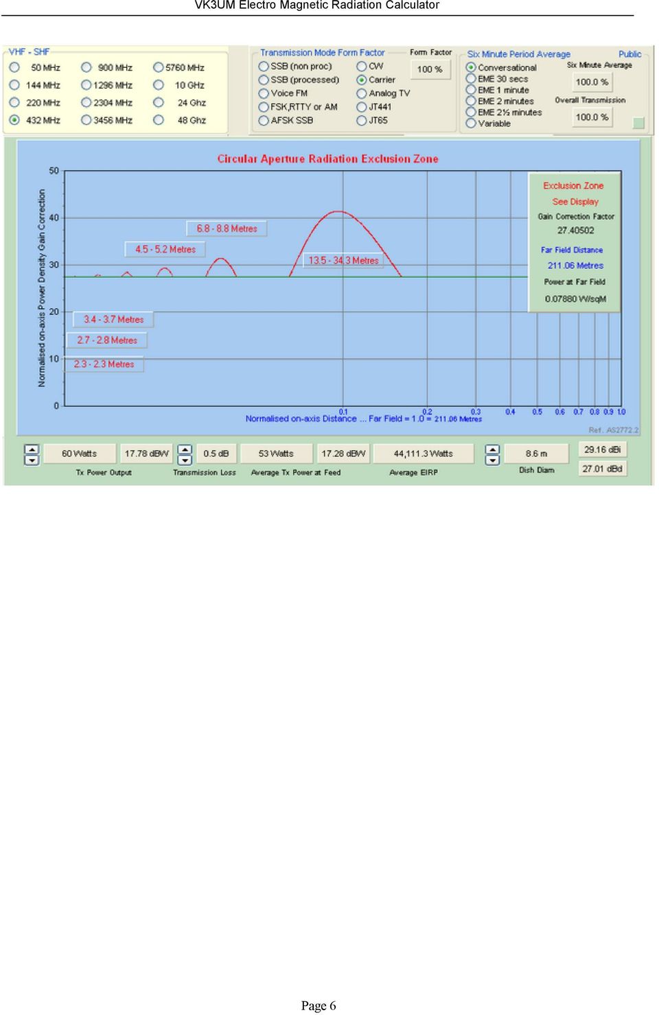
14 Circular Apertures Circular Apertures This software provides all the RF Exclusion Zone calculations as described earlier but it is now displayed in a graphical format. The level of radiated power with in the Near field region is displayed. This characteristic and the predicted Exclusion Zone could, in some circumstances, permit operation where space or elevation separation can take advantage of the safe area within the Near Field. Explanation. The X axis of the graph is the normalized on-axis distance where 1.0 equates to the Far field distance. The X base line is logarithmic. The Y axis is the normalized on-axis power density gain correction. The curve depicted in red is the on-axis power flux density curve for a circular aperture (1-q²) taper. The near-field power density is determined by calculating the far-field distance (r = 2D²/λ) and the power flux density at this point [S = GP/(4r²)] and multiplying this power flux by the gain correction factor. [Reference 3 page 28]. Example. Given a 2.16 W/square metre radiation limit, a frequency of 1296 MHz, 28.1 foot dish, efficiency 55%, 0.5 db transmission loss, 700 watts Tx O/P, a CW Transmission Mode Form Factor with a 2½ minute EME 6 minute Period Average then the display will show := Page 14

15 An Exclusion Zone as indicted by the 'red humps'; and a Far Field Distance of feet This can be interpreted as the distance from the radiator up to a distance of 21.6 feet is below the radiation limit as are the other 'holes' between the humps. As the power is increased, additional danger areas (above the set radiation level) are then revealed. The green horizontal line is the graphical representation of the radiation level in Watts/square metre as set by the user. Below this green line is below the radiation limit.. Page 15
 are then revealed.")
16 Calculation Methods Calculation Methods The On Axis Exclusion Zone is the direct line (bore sight) distance from the radiator. The distance is that where the radiation level exceeds the Radiation Limit as specified by the Standard chosen. In most Standards this will vary with frequency in accordance with the requirement. The actual level will be displayed in both Watts/metre² and mw/cm². The calculation method used by this software is that as detailed in the Australian Standard AS Radiofrequency radiation - Principles and methods of measurement khz to 100 GHz and those similarly described in FCC OET Bulletin 65. [reference 3 & 4] The program calculates the near field values for both circular and rectangular apertures depending upon the user selecting either a Parabolic reflector (circular aperture) or a Yagi, dipole or vertical radiator. (Rectangular aperture) In the case of a Parabolic reflector the near field correction follows the (1-q ²) taper curve where q is the radial distance from the center of the circular aperture, normalized to the aperture radius. The program utilises the power density (PD) in the Near Field Normalized to unity at CD ²/ where PD = 26.1 [1-16x/ sin /8x + 128x ²/²(1 - cos /8x)] [reference 5] The curve is displayed in the Circular Aperture option and highlights the near field radiation characteristic. This characteristic, where the radiation level falls below the Exclusion Zone within the near field, may of significance when establishing safe distances from antennae installations. The near field safe distance characteristic may permit operation as result of the height separation of the antennae or the elevation of the antennae. This may not be the case if the Exclusion Zone alone were the sole determining factor. It should be noted that in the On Axis Exclusion Zone calculation, only the 'first near field' curve is calculated and displayed whilst the Circular Aperture displays all near field curves and their distances. Rectangular aperture calculations (yagi) are based upon the uniform line source power density in the near field. [reference 3 & 5] Ground Reflection is as detailed in the FCC Standard. This is derived by multiplying the power density by a factor of 2.56 to equate to the predicted ground reflection as stipulated in the Standard. This option may be turned on or off as required. Check with your Licensing Authority if this is a required option for compliance. Page 16

17 Examples Examples Example 1. My tower height is 3 metres, what is the closest distance I can approach the tower? Frequency 432 MHz Power 400 watts PEP SSB (processed) Conversational 1dB Transmission Loss Antennae DJ9BV (Opt) 6 Lambda ARPANSA.. - Set the program to the above parameters (or recall Example 1) - Select the specific antenna by first clicking on top blue button on Yagi Panel and then click on DJ9BV (Opt) 6 Lambda. - Close Antennae selection by clicking elsewhere on screen. - Adjust the tower height with the mouse roller or drag the height pointer to 3.0 metres. The safe distance is given as 4.09 metres. Example 2. What is the closest distance I can approach the dish given:- Frequency 1296 MHz Power 750 watts.. CW.. 2½ minute sequence 1dB transmission loss 28ft dish (0.55% efficiency) at ground level CEU.. No ground reflection. - Set the program to the above parameters. (change to Imperial from Metric) - Select un-safe head height - Reduce tower height to zero (or recall Example 2) - The safe distance is given as feet. Example 3. What is the minimum tower height for safe operation given:- Frequency 10GHz Power 30 watts CW.. 1 minute sequence 1dB Transmission loss ARPANSA.. No ground reflection. - Set the program to the above parameters.. (or recall Example 3) The minimum safe tower height is 2.24 metres. Should you wish to increase the power to the dish (e.g. 37 watts) the near field exclusion boundaries will be indicated as and metres. This can also be seen graphically by selection of the Circular Aperture option (blue label). Page 17

18 Example 4. What is the closest distance I can approach my HF Antenna given:- Frequency 3.5 MHz Power 1500 watts Carrier.. Conversational.. 0 db transmission loss.. dipole antennae FCC.. Ground Reflection - Set the program to the above parameters. (or recall Example 4) The safe distance is given as 1.81 metres. Refer to Page 26 Tables 6 and 7 of FCC OET Bulletin 65 [ Ref 4] Example 5. What is the Exclusion Zone of my Parabolic Reflector Antenna given:- Frequency 432 MHz Power 300 watts CW.. 2½ minute sequence 2.0 db Transmission loss Mounted at ground level ARPANSA.. No ground reflection. - Set the program to the above parameters. (or recall Example 5) Using the Circular Aperture option it can be seen that it is safe from the reflector out to a distance of 14.7 meters, and above the safe radiation limit from that point out to 29.2 metres. Viz it is above safe limits from metres but less than 14.7 metres it is safe and greater than 29.2 meters it is safe as well. (safe being below the EMR limits) Example 6 What is the minimum tower height for safe operation given:- Frequency 144 MHz 4 x 2MXP32 yagi... Power 1500 watts JT db Transmission loss FCC (ground reflection).. - Set the program to the above parameters. (or recall Example 6) - Note the 2MXP32 yagi may be selected from the yagi data base (blue button) and incrementing the number of yagi to 4. Page 18
![Refer to Page 26 Tables 6 and 7 of FCC OET Bulletin 65 [ Ref 4] Example 5. What is the Exclusion Zone of my Parabolic Reflector Antenna given:- Frequency 432 MHz Power 300 watts CW.](/docs-images/49/16364721/images/page_18.jpg ". 2½ minute sequence 2.0 db Transmission loss Mounted at ground level ARPANSA.. No ground reflection. - Set the program to the above parameters.")
19 Author This program is written by Doug Mc Arthur (VK3UM) 'Tikaluna' 26 Old Murrindindi Rd, Glenburn. Victoria AUSTRALIA. (QF22ro) Page 19

20 References and Acknowledgements References and Acknowledgements [1] Australian Communication and Media Authority Human Exposure to Radiofrequency Electromagnetic Radiation [2] Australian Standard AS Radiofrequency radiation- Principles and methods of measurement khz to 100 GHz. [3] Australian Government (Common Law) Radiocommunications (Electromagnetic Radiation - Human Exposure) Standard F2011C [4] FCC OET Bulletin 65 [5] Microwave Engineers Handbook - Volume 2 [6] International Commission on Non-Ionizing Radiation Protection. (ICNIRP) I wish to make specific acknowledgement and thanks to the following persons that provided most valuable suggestions/help and beta tested versions of the software. Mr Graham Daubney (F5VHX) Mr Lyle Patison (VK2ALU) Mr Peter Blair (G3LTF) Mr Peter Sundberg (SM2CEW) Mr John Drew (VK5DJ) Mr Peter Freeman (VK3PF) Mr Trevor Pitman VK3VG and to all the other Amateurs that have provided suggestions and comment from around the World. Updated 18th May 2012 Page 20
![arpansa.gov.au/publications/codes/rps3.cfm [3] Australian Government (Common Law) Radiocommunications (Electromagnetic Radiation - Human Exposure) Standard 2003 - F2011C00165 http://www.comlaw.gov.au/details/f2011c00165/html/text#_toc288485859 [4] FCC OET Bulletin 65 http://www.](/docs-images/49/16364721/images/page_20.jpg "fcc.gov/oet/rfsafety/ [5] Microwave Engineers Handbook - Volume 2 [6] International Commission on Non-Ionizing Radiation Protection. (ICNIRP) http://www.icnirp.de/what.")
21 Page 21
VK3UM Electro-magnetic Radiation Calculator. Table of Contents
 Table of Contents Disclaimer 2 Background 3 Glossary of terms 4 Program Objectives 5 Calculations provided 6 Screen Options 8 Safe Elevation Angle 18 Australian Level 1 and Level 2 requirements 21 Screen
Electromagnetic radiation exposure: assessment against ACA mandated limits
 Electromagnetic radiation exposure: assessment against ACA mandated limits General radio services (operating above 0 MHz) (Edition May 0) Disclaimer Unless otherwise specified, the information contained
Electromagnetic radiation exposure: assessment against ACA mandated limits
 Electromagnetic radiation exposure: assessment against ACA mandated limits Paging services (Edition May 2002) Disclaimer Unless otherwise specified, the information contained in these guidelines is intended
HUMAN EXPOSURE TO EMR: ASSESSMENT OF AMATEUR RADIO STATIONS FOR COMPLIANCE WITH ACA REQUIREMENTS
 HUMAN EXPOSURE TO EMR: ASSESSMENT OF AMATEUR RADIO STATIONS FOR COMPLIANCE WITH ACA REQUIREMENTS May 2005 Version 2.0 PO Box 78 BELCONNEN ACT 2616 Telephone (02) 6219 5555 Facsimile (02) 6219 5353 www.aca.gov.au
How To Understand The Kv3Um Electro Magnetic Radiation
 Acknowledgements WIA Spectrum Committee Michael Owen.. SK VK3KI.. founder of the modern WIA. Phil Wait VK2ASD [President WIA]. Roger Harrison VK2ZRH [WIA Director]. Peter Young VK3MV [ex Director and ACMA].
Human Exposure to Radiofrequency Electromagnetic Radiation
 Australia s regulator for broadcasting, the internet, radiocommunications and telecommunications www.acma.gov.au Human Exposure to Radiofrequency Electromagnetic Radiation Information for licensees of
EMR COMPLIANCE HOW TO ENSURE YOUR NATA ACCREDITED CONTRACTOR IS ABLE TO PROVIDE A NATA ENDORSED REPORT
 EMR COMPLIANCE HOW TO ENSURE YOUR NATA ACCREDITED CONTRACTOR IS ABLE TO PROVIDE A NATA ENDORSED REPORT Chris Zombolas Technical Director, EMC Technologies Pty Ltd 57 Assembly Drive Tullamarine Vic. 3043,
SERVICES BROCHURE +61 8 9381 7199 +61 8 9381 7166. email: info@t-r-s.com.au www.t-r-s.com.au. PO BOX 680, Claremont, 6910, Western Australia
 SERVICES BROCHURE +61 8 9381 7199 +61 8 9381 7166 email: info@t-r-s.com.au www.t-r-s.com.au PO BOX 680, Claremont, 6910, Western Australia COMPANY INFORMATION Total Radiation Solutions Pty Ltd (TRS) is
Clean, Green and Safe Management System
 Clean, Green and Safe Management System SP 24-38: Working with Radio Frequency Radiation - Minimum Requirements Author : Communications Network Operations Centre Manager A. Reece Checked by: Manager Communications/
This Antenna Basics reference guide includes basic information about antenna types, how antennas work, gain, and some installation examples.
 Antenna Basics This Antenna Basics reference guide includes basic information about antenna types, how antennas work, gain, and some installation examples. What Do Antennas Do? Antennas transmit radio
Selected Radio Frequency Exposure Limits
 ENVIRONMENT, SAFETY & HEALTH DIVISION Chapter 50: Non-ionizing Radiation Selected Radio Frequency Exposure Limits Product ID: 94 Revision ID: 1736 Date published: 30 June 2015 Date effective: 30 June 2015
SITE RADIATION SURVEY
 SITE RADIATION SURVEY Site X, zzz Town XX XXXXXXX, XXXXXXX Site ID No: 12345 Dated: 29.09.2007 1 CONTENTS 1.0 SCOPE... 3 2.0 EQUIPMENT... 4 3.0 TRANSMITTERS... 5 4.0 FM Antenna Details... 7 6.0 GENERAL...
Electromagnetic Radiation Compatibility Survey and Safety Analysis around Mobile Base Transceiver Stations: Case Studies around Kathmandu Valley
 Research Journal of Engineering Sciences ISSN 2278 9472 Electromagnetic Radiation Compatibility Survey and Safety Analysis around Mobile Base Transceiver Stations: Case Studies around Kathmandu Valley
EMR Exposure Limits & Assessment Methods for Mobile Phone Communications. Lindsay Martin Manager, Non-Ionising Radiation Section
 EMR Exposure Limits & Assessment Methods for Mobile Phone Communications Lindsay Martin Manager, Non-Ionising Radiation Section Introduction How can we use Wireless Communication Safely? Wireless communication
Millennium Product Inc. Model: Cell Shield / Zorb
 Millennium Product Inc. Cell Shield / Zorb Prepared by PCTEST LAB Issued on: 10/22/2015 Report Version 2.6 NOTE: SAR results only apply to the device tested. Although the device may have had different
Keywords Mobile Tower Radiations, Electromagnetic Radiations, Signal Strength, Mobile Phone
 Volume 5, Issue 1, January 2015 ISSN: 2277 128X International Journal of Advanced Research in Computer Science and Software Engineering Research Paper Available online at: www.ijarcsse.com Analysis of
Working safely around Radiofrequency (RF) Transmitters
 Transmitters") Working safely around Radiofrequency (RF) Transmitters Exposure to excessive levels of radiofrequency (RF) emissions may affect your health This Mobile Carriers Forum (MCF) Fact sheet series is designed
Working safely around Radiofrequency (RF) Transmitters Exposure to excessive levels of radiofrequency (RF) emissions may affect your health This Mobile Carriers Forum (MCF) Fact sheet series is designed
Product Safety and RF Exposure for Mobile Two-Way Radios Installed in Vehicles or as Fixed Site Control Stations
 Product Safety and RF Exposure for Mobile Two-Way Radios Installed in Vehicles or as Fixed Site Control Stations! C a u t i o n BEFORE USING THIS RADIO, READ THIS BOOKLET WHICH CONTAINS IMPORTANT OPERATING
RF safety at base station sites
 RF safety at base station sites CONTENTS 1 Purpose and scope................................................. 2 2 Introduction........................................................ 2 3 Basic information...................................................
RF EXPOSURE LIMITS AND TESTING REQUIREMENTS
 RF EXPOSURE LIMITS AND TESTING REQUIREMENTS Jay Moulton Vice President March 12, 2013 1 OVERVIEW Specific Absorption Rate (SAR) and Maximum Permissible Exposure (MPE) Standards and Limits Evaluation Methods
OpenWay Radio Frequency FAQ
 OpenWay Radio Frequency FAQ March 10, 2010 2010, Itron Inc. All rights reserved. 1 Overview This document provides general information about radiofrequency (RF) electromagnetic fields from OpenWay wireless
EE302 Lesson 14: Antennas
 EE302 Lesson 14: Antennas Loaded antennas /4 antennas are desirable because their impedance is purely resistive. At low frequencies, full /4 antennas are sometime impractical (especially in mobile applications).
Antenna Deployment Technical Brief
 ProCurve Networking Antenna Deployment Technical Brief Introduction... 2 Antenna types... 2 Omni directional antennas... 2 Directional antennas... 2 Diversity antennas... 3 High gain directional antennas...
Antenna Properties and their impact on Wireless System Performance. Dr. Steven R. Best. Cushcraft Corporation 48 Perimeter Road Manchester, NH 03013
 Antenna Properties and their impact on Wireless System Performance Dr. Steven R. Best Cushcraft Corporation 48 Perimeter Road Manchester, NH 03013 Phone (603) 627-7877 FAX: (603) 627-1764 Email: sbest@cushcraft.com
The field strength measurement and SAR experience related to human exposure in 110 MHz to 40 GHz
 The field strength measurement and SAR experience related to human exposure in 110 MHz to 40 GHz J. Klima, R. Ščehovič Department of Physics, Faculty of Natural Sciences, University of Mathias Bel, Tajovského
Human Exposure Limits
 Human Exposure Limits Session 3 0 Version December 2014 Learning objectives In this session we will: Learn about the international exposure limits for workers and the public Learn about methods for assessing
MEASUREMENT AND ANALYSIS OF RF EME LEVELS FROM MOBILE TELEPHONE BASE STATIONS LOCATED AT LEICHHARDT, NSW
 AUSTRALIAN RADIATION PROTECTION AND NUCLEAR SAFETY AGENCY A R P N S A Lower Plenty Road YALLAMBIE VIC 3085 Phone 61 3 9433 2211 Fax 61 3 9432 1835 E-mail: arpansa@health.gov.au Web: www.arpansa.gov.au
Antenna Basic Concepts
 ANTENNA An antenna is a device to transmit and/or receive electromagnetic waves. Electromagnetic waves are often referred to as radio waves. Most antennas are resonant devices, which operate efficiently
102 26-m Antenna Subnet Telecommunications Interfaces
 DSMS Telecommunications Link Design Handbook 26-m Antenna Subnet Telecommunications Interfaces Effective November 30, 2000 Document Owner: Approved by: Released by: [Signature on file in TMOD Library]
PRO 5000 CPE 1D Quick Installation Guide
 PRO 5000 CPE 1D Quick Installation Guide Introduction This Quick Installation Guide covers the basic installation of the PRO 5000 CPE. For more information, refer to the relevant sections in the Product
Technical limits of Human Exposure to RF from Cellular Base Stations and Handsets
 Ministry of Environmental Protection Ministry of Communications Technical limits of Human Exposure to RF from Cellular Base Stations and Handsets Based on author s PhD thesis/book- An analysis of regulatory
Guidelines on the assessment of installations against electromagnetic radiation (EMR) exposure limits
 exposure limits") Guidelines on the assessment of installations against electromagnetic radiation (EMR) exposure limits (Edition eptember 000) Disclaimer Unless otherwise specified, the information contained in these guidelines
Guidelines on the assessment of installations against electromagnetic radiation (EMR) exposure limits (Edition eptember 000) Disclaimer Unless otherwise specified, the information contained in these guidelines
What are radio signals?
 Mobile phones and other wireless technologies have become an integral part of everyday life. But does using a mobile phone regularly, or living near a base station, have any implications for our health?
Radio Frequency Exposure Test Report
 Radio Frequency Exposure EN 62311 January 2008 Assessment of electronic and electrical equipment related to human exposure restrictions for electromagnetic fields (0Hz 300GHz) (IEC 62311:2007, modified)
Fixed Wireless Fact Sheet
 National Broadband Network Fixed Wireless Fact Sheet What is the National Broadband Network? The National Broadband Network (NBN) is designed to provide high speed broadband access to 100 per cent of Australian
ELECTROMAGNETIC FIELDS AND PUBLIC HEALTH HEALTH AND SAFETY GUIDELINES #1
 SINGAPORE, 16 AUGUST 2001 HEALTH SCIENCES AUTHORITY PRESS RELEASE ELECTROMAGNETIC FIELDS AND PUBLIC HEALTH HEALTH AND SAFETY GUIDELINES #1 THE EMF HEALTH ISSUE 1 Over the past years a large number of scientific
Radio Frequency Electromagnetic Energy (RF-EME) Compliance Report (Predictive Modeling)
 Compliance Report (Predictive Modeling)") Radio Frequency Electromagnetic Energy (RF-EME) Compliance Report (Predictive Modeling) Prepared for: AT&T Mobility, LLC 7655-7665 Redwood Blvd. Novato,CA 94945 USID# 118154 Site No. CNU2701 DUCKHORN DR.
Radio Frequency Electromagnetic Energy (RF-EME) Compliance Report (Predictive Modeling) Prepared for: AT&T Mobility, LLC 7655-7665 Redwood Blvd. Novato,CA 94945 USID# 118154 Site No. CNU2701 DUCKHORN DR.
COMMUNICATIONS AND MULTIMEDIA ACT 1998 NOTIFICATION OF ISSUANCE OF CLASS ASSIGNMENTS
 COMMUNICATIONS AND MULTIMEDIA ACT 1998 NOTIFICATION OF ISSUANCE OF CLASS ASSIGNMENTS IN exercise of the powers conferred by section 169 of the Communications and Multimedia Act 1998 [Act 588], the Commission
Smart meters: Compliance with radio frequency exposure standards
 Smart meters: Compliance with radio frequency exposure standards Summary Smart meters use low power radio frequency signals to collect and transmit information about use of services such as electricity,
Technician Licensing Class
 Technician Licensing Class Antennas Presented by Amateur Radio Technician Class Element 2 Course Presentation ELEMENT 2 SUB-ELEMENTS (Groupings) About Ham Radio Call Signs Control Mind the Rules Tech Frequencies
Measurements of radiofrequency fields from a WEL Networks Smart Meter
 Measurements of radiofrequency fields from a WEL Networks Smart Meter Report 2012/36 This report was prepared for: WEL Networks Ltd P O Box 925 Hamilton Report prepared by: Martin Gledhill Finalised: 7
Selecting Receiving Antennas for Radio Tracking
 Selecting Receiving Antennas for Radio Tracking Larry B Kuechle, Advanced Telemetry Systems, Inc. Isanti, Minnesota 55040 lkuechle@atstrack.com The receiving antenna is an integral part of any radio location
THE ANSI/IEEE RF SAFETY STANDARD AND ITS RATIONALE. Om P. Gandhi and Gianluca Lazzi Department of Electrical Engineering Salt Lake City, Utah 84112
 Introduction THE ANSI/IEEE RF SAFETY STANDARD AND ITS RATIONALE Om P. Gandhi and Gianluca Lazzi Department of Electrical Engineering Salt Lake City, Utah 84112 In 1960, the American Standards Association
You will need the following pieces of equipment to complete this experiment:
 UNIVERSITY OF TORONTO FACULTY OF APPLIED SCIENCE AND ENGINEERING The Edward S. Rogers Sr. Department of Electrical and Computer Engineering ECE422H1S: RADIO AND MICROWAVE WIRELESS SYSTEMS EXPERIMENT 3:
Amplification of the Radiation from Two Collocated Cellular System Antennas by the Ground Wave of an AM Broadcast Station
 Amplification of the Radiation from Two Collocated Cellular System Antennas by the Ground Wave of an AM Broadcast Station Dr. Bill P. Curry EMSciTek Consulting Co., W101 McCarron Road Glen Ellyn, IL 60137,
Antenna Glossary Before we talk about specific antennas, there are a few common terms that must be defined and explained:
 Antenna Basics Introduction Antennas are a very important component of communication systems. By definition, an antenna is a device used to transform an RF signal, traveling on a conductor, into an electromagnetic
COMMON REGULATORY OBJECTIVES FOR WIRELESS LOCAL AREA NETWORK (WLAN) EQUIPMENT PART 2 SPECIFIC ASPECTS OF WLAN EQUIPMENT
 EQUIPMENT PART 2 SPECIFIC ASPECTS OF WLAN EQUIPMENT") COMMON REGULATORY OBJECTIVES FOR WIRELESS LOCAL AREA NETWORK (WLAN) EQUIPMENT PART 2 SPECIFIC ASPECTS OF WLAN EQUIPMENT 1. SCOPE This Common Regulatory Objective, CRO, is applicable to Wireless Local Area
COMMON REGULATORY OBJECTIVES FOR WIRELESS LOCAL AREA NETWORK (WLAN) EQUIPMENT PART 2 SPECIFIC ASPECTS OF WLAN EQUIPMENT 1. SCOPE This Common Regulatory Objective, CRO, is applicable to Wireless Local Area
Exposure to Radio Waves near Mobile Phone Base Stations
 NRPB-R Exposure to Radio Waves near Mobile Phone Base Stations S M Mann, T G Cooper, S G Allen, R P Blackwell and A J Lowe Abstract Measurements of power density have been made at 7 sites where people
Understanding Range for RF Devices
 Understanding Range for RF Devices October 2012 White Paper Understanding how environmental factors can affect range is one of the key aspects to deploying a radio frequency (RF) solution. This paper will
Appendix 1. The Existing Regulatory Scheme Comprises:
 The Existing Regulatory Scheme Comprises: A. An Act about management of the radiofrequency spectrum and other matters. The short title is Radiocommunications Act (Cth) No. 174 1992 as amended; B. An Act
Nardalert S3 Non-Ionizing Radiation Monitor
 Patent Pending Non-Ionizing Radiation Monitor Field Replaceable Sensor Modules Color LCD Display Multi-Color Alarm LED s USB Interface for Data and Charging Interchangeable Lanyard or Belt Clips Comprehensive
sources in our environment i.e. Natural and man-made. The sun, earth and ionosphere are the natural source.
 Electromagnetic Radiation (EMR) consist of waves of electric and magnetic energy moving together at the speed of light and sometimes is referred as electromagnetic field (EMF) They are basically two forms
is the power reference: Specifically, power in db is represented by the following equation, where P0 P db = 10 log 10
 RF Basics - Part 1 This is the first article in the multi-part series on RF Basics. We start the series by reviewing some basic RF concepts: Decibels (db), Antenna Gain, Free-space RF Propagation, RF Attenuation,
Antennas 101 The Basics. Ward Silver NØAX
 Antennas 101 The Basics Ward Silver NØAX The Basics - 1 Antennas radiate (or receive) because electrons are accelerated (or are caused to accelerate) in the antenna s elements Radio or electromagnetic
GSM Base Station Radiation Level: A Case Study of University of Nigeria Environment
 INTERNATIONAL JOURNAL OF SCIENTIFIC & TECHNOLOGY RESEARCH VOLUME 1, ISSUE 8, SEPTEMBER 212 ISSN 2277-8616 GSM Base Station Radiation Level: A Case Study of University of Nigeria Environment Mamilus. A.
FREQUENCY ASSIGNMENT REQUIREMENTS FOR THE LAND MOBILE SERVICE
 RALI : LM 8 DATE OF EFFECT : 23/09/2015 Radiocommunications Assignment and Licensing Instruction FREQUENCY ASSIGNMENT REQUIREMENTS FOR THE LAND MOBILE SERVICE AUSTRALIAN COMMUNICATIONS AND MEDIA AUTHORITY
Antenna Trainer EAN. www.edibon.com. Technical Teaching Equipment INTRODUCTION
 Antenna Trainer EAN Technical Teaching Equipment Products Products range Units 3.-Communications INTRODUCTION Antennas are the main element of aerial communications. They are the transition between a transmission
MANAGEMENT OF BI-DIRECTIONAL AMPLIFIERS IN THE LAND MOBILE SERVICE IN THE FREQUENCY RANGE 29.7 MHz TO 520 MHz
 RALI : LM 6 DATE OF EFFECT :.13/03/96 Sequence Number :.66 Radiocommunications Assignment and Licensing Instruction MANAGEMENT OF BI-DIRECTIONAL AMPLIFIERS IN THE LAND MOBILE SERVICE IN THE FREQUENCY RANGE
Analysis of the G3LTF Dual Band Feed for 23cm and 13cm Paul Wade W1GHZ 2004 w1ghz@arrl.net
 Analysis of the G3LTF Dual Band Feed for 23cm and 13cm Paul Wade W1GHZ 2004 w1ghz@arrl.net In the March 2004 edition of the RSGB Microwave Newsletter, G3LTF described 1 a dual band feed for the 23 cm and
Just a Dipole. Gary Wescom N0GW July 16, 2007
 Just a Dipole Gary Wescom N0GW July 16, 2007 Often we will hear people describing their antennas as just a dipole. After all, a coax cable fed, half wavelength dipole is one of the simplest antennas to
IJMIE Volume 2, Issue 5 ISSN: 2249-0558
 AN OPTIMAL DETECTION TECHNIQUE FOR MOBILE RADIO FREQENCIES M.SUCHARITHA* T.JAHNAVI* N.POORNIMA* P.KRISHNA SILPHA* K MURALI** ABSTRACT: Cellular phone technology is rapidly changing. Features like Bluetooth,
AN INTRODUCTION TO TELEMETRY PART 1: TELEMETRY BASICS
 AN INTRODUCTION TO TELEMETRY PART 1: TELEMETRY BASICS Telemetry is defined as the sensing and measuring of information at some remote location and then transmitting that information to a central or host
Antennas & Propagation. CS 6710 Spring 2010 Rajmohan Rajaraman
 Antennas & Propagation CS 6710 Spring 2010 Rajmohan Rajaraman Introduction An antenna is an electrical conductor or system of conductors o Transmission - radiates electromagnetic energy into space o Reception
Wireless Broadband: Health & Safety Information
 Wireless Broadband: Health & Safety Information Introduction The increasing use of mobile phones and other wireless technology has been accompanied by public debate about possible adverse effects on health.
The Salzburg Model: A Precautionary Strategy for Siting of Base Stations
 The Salzburg Model: A Precautionary Strategy for Siting of Base Stations Dr. Gerd Oberfeld, Dr. Christoph König Federal State of Salzburg, Public Health Department, Environmental Health P.O. Box 527, A-5010
SR Communications Tower Task Force Dr. Jeff Liva, Allen Cohen, Rebecca Rogers
 SR Communications Tower Task Force Dr. Jeff Liva, Allen Cohen, Rebecca Rogers 1 Table of Contents 2 Chemical hazards. These develop from excessive exposure to concentrations of chemicals in environment.
Regional Emergency Communications. John Walters W8CX Alpena RACES
 Regional Emergency Communications John Walters W8CX Alpena RACES Regional Communications Needs 400 mile radius No skip zone; no dead spots No interference with or from broadcasters Reliable day/night coverage
ARIB TR-T12-34.925 V3.0.0. Specific Absorption Rate (SAR) requirements and regulations in different regions
 requirements and regulations in different regions") ARIB TR-T12-34.925 V3.0.0 Specific Absorption Rate (SAR) requirements and regulations in different regions Refer to "Notice" in the preface of ARIB TR-T12 for Copyrights. Technical Report 3rd Generation
ARIB TR-T12-34.925 V3.0.0 Specific Absorption Rate (SAR) requirements and regulations in different regions Refer to "Notice" in the preface of ARIB TR-T12 for Copyrights. Technical Report 3rd Generation
RWANDA UTILITIES REGULATORY AGENCY P.O BOX 7289 KIGALI,
 REPUBLIC OF RWANDA RWANDA UTILITIES REGULATORY AGENCY P.O BOX 7289 KIGALI, Tel: +250 252 584562, Fax: +250 252 584563 Email: arms@rwanda1.com Website: www.rura.gov.rw GUIDELINES FOR LIMITING HUMAN EXPOSURE
ETSI TR 101 870 V1.1.1 (2001-11)
") TR 101 870 V1.1.1 (2001-11) Technical Report Fixed radio transmitter sites; Exposure to non-ionising electromagnetic fields; Guidelines for working conditions 2 TR 101 870 V1.1.1 (2001-11) Reference DTR/SAFETY-00004
TR 101 870 V1.1.1 (2001-11) Technical Report Fixed radio transmitter sites; Exposure to non-ionising electromagnetic fields; Guidelines for working conditions 2 TR 101 870 V1.1.1 (2001-11) Reference DTR/SAFETY-00004
AN1200.04. Application Note: FCC Regulations for ISM Band Devices: 902-928 MHz. FCC Regulations for ISM Band Devices: 902-928 MHz
 AN1200.04 Application Note: FCC Regulations for ISM Band Devices: Copyright Semtech 2006 1 of 15 www.semtech.com 1 Table of Contents 1 Table of Contents...2 1.1 Index of Figures...2 1.2 Index of Tables...2
Manual for simulation of EB processing. Software ModeRTL
 1 Manual for simulation of EB processing Software ModeRTL How to get results. Software ModeRTL. Software ModeRTL consists of five thematic modules and service blocks. (See Fig.1). Analytic module is intended
The W5JCK Guide to the Mathematic Equations Required for the Amateur Extra Class Exam
 The W5JCK Guide to the Mathematic Equations Required for the Amateur Extra Class Exam This document contains every question from the Extra Class (Element 4) Question Pool* that requires one or more mathematical
COMMUNICATIONS ALLIANCE LTD INDUSTRY CODE C564:2011 MOBILE PHONE BASE STATION DEPLOYMENT
 COMMUNICATIONS ALLIANCE LTD INDUSTRY CODE C564:2011 MOBILE PHONE BASE STATION DEPLOYMENT Industry Code - Mobile Phone Base Station Deployment This Code was issued in draft form for public comment as DR
What the experts say: The consensus of scientific opinion
 What the experts say: The consensus of scientific opinion AMTA relies on the expert judgment of independent public health authorities, such as the World Health Organization, for assessments of safety and
Part I: Wireless System Characteristics
 Part I: Wireless System Characteristics Smart grid technology holds great promise of cleaner air, more efficient power, and lower greenhouse gas emissions. In a smart grid system, the system itself will
Advanced Measurements of Microwave Oven Leakage
 Conference paper Advanced Measurements of Microwave Oven Leakage M. Bangay [1] C. Zombolas [2] 1. Australian Radiation Protection and Nuclear Safety Agency 2. EMC Technologies Pty Ltd Abstract Reports
The Existing Public Exposure Standards Cindy Sage, MA Sage Associates, USA
 SECTION 3 _ The Existing Public Exposure Standards Cindy Sage, MA Sage Associates, USA Prepared for the BioInitiative Working Group August 2007 The US Federal Communications Commission (FCC) Exposure Standard
Isolation between antennas of IMT base stations in the land mobile service
 Report ITU-R M.44 (11/011) Isolation between antennas of IMT base stations in the land mobile service M Series Mobile, radiodetermination, amateur and related satellite services ii Rep. ITU-R M.44 Foreword
Mobile Phone Base-Station Audit
 Mobile Phone Base-Station Audit Audit site: Aylesbury Road Wing Leighton Buzzard Beds LU7 0NY The Office of Communications (Ofcom) is responsible for management of the civil radio spectrum in the UK. Following
ELECTROMAGNETIC ENERGY Evaluation and Management for Antenna Sites
 ELECTROMAGNETIC ENERGY Evaluation and Management for Antenna Sites 10/9/97 Revised 12/27/2001 The purpose of this document is to provide information to assist the reader in understanding the concepts required
No. S8351. S8351 External Bluetooth module for mz series transmitter OPERATING INSTRUCTION
 No. S8351 S8351 External Bluetooth module for mz series transmitter OPERATING INSTRUCTION Prior to use, please read this manual thoroughly. Keep this manual in a convenient place for quick and easy reference.
FOR EXISTING 254-FOOT COMMUNICATIONS TOWER 16700 Skyline Drive La Habra Heights California
 MASTER PLAN FOR EXISTING 254-FOOT COMMUNICATIONS TOWER 16700 Skyline Drive La Habra Heights California PROPERTY OWNER: Coast Community College District 1370 Adams Avenue Costa Mesa, CA 92626 Attn: Richard
Pillbox Antenna for 5.6 GHz Band Dragoslav Dobričić, YU1AW dragan@antennex.com
 Pillbox Antenna for 5.6 GHz Band Dragoslav Dobričić, YU1AW dragan@antennex.com Introduction The pillbox or cheese antenna is made of two parallel plates which are connected to the narrow strip of parabolic
RADIATION PATTERNS. The half-power (-3 db) beamwidth is a measure of the directivity of the antenna.
 beamwidth is a measure of the directivity of the antenna.") RADIATION PATTERNS The radiation pattern is a graphical depiction of the relative field strength transmitted from or received by the antenna. Antenna radiation patterns are taken at one frequency, one
RADIATION PATTERNS The radiation pattern is a graphical depiction of the relative field strength transmitted from or received by the antenna. Antenna radiation patterns are taken at one frequency, one
Understanding SWR by Example
 Understanding SWR by Example Take the mystery and mystique out of standing wave ratio. Darrin Walraven, K5DVW It sometimes seems that one of the most mysterious creatures in the world of Amateur Radio
Effects of Mobile Phone Radiation onto Human Head with Variation of Holding Cheek and Tilt Positions
 Effects of Mobile Phone Radiation onto Human Head with Variation of Holding Cheek and Tilt Positions M. R. Iqbal-Faruque* 1, N. Aisyah-Husni 2, Md. Ikbal-Hossain 1, M. Tariqul-Islam 2 and N. Misran 2 1
Automated Meter Reading Frequently Asked Questions. What is AMR?
 Automated Meter Reading Frequently Asked Questions What is AMR? AMR stands for Automated Meter Reading. It is a method of using advanced communications technology to read meters remotely. It reduces human
Avaya WLAN 9100 External Antennas for use with the WAO-9122 Access Point
 Avaya WLAN 9100 External Antennas for use with the WAO-9122 Access Point Overview To optimize the overall performance of a WLAN in an outdoor deployment it is important to understand how to maximize coverage
CELL PHONE TOWERS TOWN OF INNISFIL
 CELL PHONE TOWERS TOWN OF INNISFIL Dr. Jim Pfaff, MD, BSc, MHSc, DAvMed, Associate Medical Officer of Health Marina Whelan, CPHI (C), BSc., Manager, Health Hazards Lori Holmes, CPHI (C), BASc, Coordinator,
REVIEW OF EXPOSURE LIMITS AND HEALTH CONCERNS SANTA ANA. Base Station Telecommunication Transmitters UNIFIED SCHOOL DISTRICT
 SANTA ANA UNIFIED SCHOOL DISTRICT REVIEW OF EXPOSURE LIMITS AND HEALTH CONCERNS Base Station Telecommunication Transmitters Dr. Karl Rodenbaugh, Senior Scientist SCOPE OF SERVICES Review, Describe, Discuss,
Real-life Applications of ICNIRP Guidelines to Various Human EMF Exposure Issues
 Technical Forum Overview and Latest Development of Standards in Human Exposure to Electromagnetic Fields (EMF) Real-life Applications of ICNIRP Guidelines to Various Human EMF Exposure Issues Dr. Brian
LTE: Technology and Health. 4G and Mobile Broadband
 LTE: Technology and Health 4G and Mobile Broadband LTE Technology and Health Mobile Broadband typically refers to providing customers with high speed data while on the move. There are several technologies
Selecting a Transmission Line for Your Broadcast System
 Selecting a Transmission Line for Your Broadcast System Introduction This Bulletin presents the procedures broadcasters need for calculating attenuation and power handling parameters to properly design
Radiation Protection Series
 Radiation The Radiation is published by the Australian Radiation and Nuclear Safety Agency (ARPANSA) to promote practices which protect human health and the environment from the possible harmful effects
A Tutorial on the Decibel
 A Tutorial on the Decibel This tutorial combines information from several authors, including Bob DeVarney, W1ICW; Walter Bahnzaf, WB1ANE; and Ward Silver, NØAX Decibels are part of many questions in the
Dr MH Repacholi Co-ordinator. ordinator,, Radiation and Environmental Health World Health Organization, Geneva, Switzerland
 Dr MH Repacholi Co-ordinator ordinator,, Radiation and Environmental Health World Health Organization, Geneva, Switzerland WHO EMF Project Scientific Evidence Risk Assessment Standards and Policies Risk
Application Note AN-00126
 Considerations for Operation within the 902-928MHz Band Application Note AN-00126 Introduction This application note is designed to give the reader a basic understanding of the legal and technical considerations
College of Engineering, University of Kirkuk, -IRAQ
 Comparative Study of Radiofrequency Radiations from GSM Base Stations in Residential Areas Sabah Hawar Saeid Abstract: As technology progresses and data demands have increased on mobile network, towns