at a temperature of 37⁰F, the cost per therm of heat (100,000btu) is about 2.5x 3.3KW/H =8.25KW/H.
|
|
|
- Ashley Bates
- 8 years ago
- Views:
Transcription
1 Improved Defrost Cycle for Heat Pump Systems and Comparisons of heating systems for Moderate Climates (like Georgia) by Joe Mehaffey Rev 12, January 5, 2008 (added new graph(s)) A new heat pump defrost control cycle is described which is shown to dramatically reduce the number of defrost cycles needed by heat pumps in the author's environment. The costs involved in this control cycle implementation if done on a production basis would probably be less than $25 which would be easily recovered in less than one year of operation. Some Preliminary Information In the summer of 2007, I installed a Carrier Heat Pump for a client in the Atlanta, Georgia area. This change-out was designed to improve the efficiency of the heating and cooling equipment. The 25HNA9 heat pump was a 48000btu/h unit with SEER rated 19 and a COP in heating mode of about 3 at 27⁰F and about 4 at 37⁰F. As an example, this means that for a total input of about 3.3KW (equivalent to about 10,800btuh) at 34⁰F, the heating system outputs about 40,000btuh into the building. According to Carrier data, at a temperature of 37⁰F, the cost per therm of heat (100,000btu) is about 2.5x 3.3KW/H =8.25KW/H. Here in Georgia, the "all up" cost per KW/H on the residential TOU rate in winter is about 8cents per KW/h. So the cost to move 1 Therm of heat from outside (37⁰F) to the inside of the house is about 8.25kwh x 8cents per KWH = $0.66 at a nominal outside temperature of 37⁰F. This compares to about $1.50 per therm as an "all up" cost per therm for Natural Gas (95% efficiency furnace). For fuel oil at about $2.50 per gallon you get about 140,000btu per gallon and with a 90% efficiency Oil Furnace the cost per therm is about $1.98 per therm. Similarly for electric RESISTANCE heat which is often used as supplemental heat for heat pumps, the cost per therm is again about 8cents per KW/H and you get 3413 Btu/h per KW/H. Thus 100,000btuh will cost (100000/3413) x 8c = $2.35 per therm. In summary, with the SEER =19/COP = 4 (at T=37⁰F) heat pumps available now AND with a reasonable electric energy cost such as we have here in Georgia, the obvious solution for home heating is a heat pump with whatever backup heat (Nature Gas/Propane/Fuel Oil/Electric) that is best for your area. NOTE: Heat pumps WILL NOT be as efficient in colder northern climates, so you must run a calculation similar to the above to determine costs in your area at various temperatures. With the above in mind, we installed the heat pump system and an adjunct high efficiency (SEER=17) Air Conditioner and the client enjoyed a summer with about a 25% lower overall electric energy cost compared to that using the older SEER 12 air conditioners. Cheers!

2 The Carrier 25HNA9 48,000btuh "Ultra" Heat Pump System. This Heat pump system is a LITTLE unusual. The unit was purchased with the thinking that it would be rather simple to connect it up to the existing furnace and zoned control system. What a surprise when I opened the manual and it said, This equipment can only be used with Carrier Furnaces and Infinity Thermostats"... After mulling things over for a day, we found that there were no readily available air source heat pump systems with the efficiency of the one we had bought. So... Since I am an Electrical Engineer by trade, we set about to figure out WHY this heat pump could not be used with "ordinary" furnaces. The answer was: A marketing decision was made to integrate the furnace, heat pump, thermostats and zones so that they would "talk" only over a pair of wires. I am sure that somewhere along the way, the marketers figured this was a good way to force anyone wanting Carrier's premium heat pump product to "Go Carrier All The Way". I think that perhaps this is a great marketing strategy for Carrier and it eliminates any potential equipment compatibility problems and allows certain system optimizations as well. BUT! I wanted to use the 25HNA9048 heat pump with the existing 12 year old stainless firebox 95% efficiency Amana Furnace. The installed Building Automation System is a system designed and manufactured by HI Solutions Inc. The system was designed for use in LARGE commercial buildings but it uses a distributed architecture that makes it quite adaptable (by an HVAC Engineer) and cost effective to use for buildings of any size, including medium to large sized homes. Since this system was already up and running in the home and grounds, we chose the HI Solutions model UUC-8 Universal Controller to REPLACE the Carrier Heat Pump Controller Card inside the heat pump. This meant we had to adapt the basic heat pump to operate with the new UUC-8 controller AND program this controller so it could both control and protect the heat pump and also communicate and interface with the remainder of the building automation system. This process took several days. I was able to procure product literature from Carrier which described in some detail how their controller functioned and I simply wrote a 40 line program for the UUC-8 universal controller (in a language similar to BASIC) to operate and monitor the heat pump equipment. While I was at it, I added a few instrumentation "niceties" so we could monitor the detailed performance of the heat pump from my remote computers. The UUC-8 controller has 8 Analog Inputs, 12 Switch Closure Inputs, 3 Analog Outputs, and 8 ports with Triac Switchable 24vac at up to 2 amps. I set up the new UUC-8 controller to control the scroll compressor, reversing solenoid, and the High/Low capacity solenoid in the heat pump compressor unit itself. Then we added a "furnace run (enable GAS)" signal, a furnace Fan High/Low signal, an overall FURNACE ENABLE signal, and a Heat Pump/Furnace select signal. The technician built a simple relay tree interface for the furnace end so that any single wire or signal failure could not put the furnace (or the heat pump) in RUN and leave it there. As an added safety feature, a standard Honeywell thermostat was connected in series with the furnace system's gas valve so that if return air ever gets over 80⁰F, the gas valve in the furnace cannot be turned on. On a "one of a kind" system such as this, MULTIPLE safeguards are an essential ingredient because

3 "errors happen" and you do not want a small "program error" to overheat your client's house!! One of the analog outputs go to control the GE variable speed fan in the heat pump unit, Analog input sensors monitor Outside Air temperature, Evaporator refrigerant OUTLET temperature, and Suction Line temp on the line coming from the furnace evaporator/condenser. UUC-8 switch closure inputs include Puron Over-Pressure, Puron Under-Pressure, plus an input from the furnace air vane switch which proves furnace air flow. (The compressor is never allowed to run unless air flow in the connected furnace air handler is "proved".). Then a current transformer was added so as to be able to monitor heat pump compressor and outside fan unit current draw. This, along with the other data available in the UUC-8 allows the computation of a good quality estimate of the system SEER, COP, and to allow the program to monitor for over-current, over-temperature, overpressure and various other abnormal conditions as may arise. What about the DEFROST CYCLE is so interesting? In November, North Georgia weather turned rather cool. Night low temperatures were going from 27⁰F to about 45⁰F which has allowed a good laboratory for getting the heat pump right down to freezing for a few hours and then quickly bringing the temperature into the 50 to 70 range in the daytime. During this interval, I noticed via the remote instrumentation that the heat pump was going into defrost mode in the 3am to 8am time period but we found that the defrosts were producing little water. I was basically using Carrier's defrost algorithm which goes like this: You power up and the system resets the defrost interval to a value of 30 minutes of compressor running time in heating mode. Then, after this 30 minutes expires, the temperature of the evaporator refrigerant outlet line is measured and if it is less than 32⁰F a defrost cycle is initiated. Then, when a defrost cycle is initiated, if the time it takes to defrost the outside evaporator coil (as evidenced by the outside coil exhaust temperature being greater than 65⁰F) is less than 3 minutes, the next defrost interval is set to 120 minutes, if between 3 and 5 minutes set the defrost interval to 90 minutes, if between 5 and 7 minutes, set the defrost interval to 60 minutes, and if it takes greater than 7 minutes to defrost the evaporator, set the next defrost interval to 30 minutes. The decision to defrost (or not) is that AFTER the compressor runs for the defrost interval, check the outside coil refrigerant outlet temperature. If it is below 32⁰F, then defrost, if not, reset the timer and continue operations. This algorithm leads to unneeded defrost cycles where the coil is really NOT iced up to an extent affecting efficiency in a significant way. We noticed that a good many defrosts (1 to 3 a day) produced little water from the defrost cycle. I was a bit curious as to the "real" amount of ice being developed and so we temporarily disabled the defrost part of the program but left in a "freeze up shutoff" if the coil temperature ever got down to 15⁰F. The equipment was watched remotely for another week and the outside refrigerant outlet temperature never got lower than 22⁰F and never differed from the outside air temperature by more than about 8 degrees. (Did I mention that the UUC-8 also has trend logging for analog and digital inputs and most any internal variable you may wish to log for later review? The log comes complete with a date/time stamp.) In this case, we logged what would have been defrosting cycles. There were 19 in a 10 day period but NOT ONE was actually needed. I decided that there had to

4 be a better way to determine WHEN to defrost so as not to waste the energy used in the defrost cycle. A typical defrost cycle lasts about 4 minutes and pumps "cool" air into the house and warms up the outside evaporator thus causing any ice to melt. Then when the heat pump is reversed back to heating mode, it takes LONGER to pump the heat back into the house than the defrost cycle took. All in all you are "defrosting and getting back where you were" to the tune of maybe 10 minutes or more for each defrost cycle. The energy used is in the range of 3KW (at 33⁰F) for 1/6 hour or about 4 cents per defrost. This is not a great deal of money per cycle, but you ALSO lose the heat pump capacity for those 10 minutes which amounts to perhaps 7000btu for the average defrost cycle. Note that even more energy is used for the defrost cycle when electric heat is used to compensate for the cooling effect in the home due to the defrost cycle. In fact, a defrost cycle compensated by electric heat will cost about 9 cents for each defrost cycle... Another reason for wanting to try and optimize the defrost cycle was to try to be able to operate the heat pump at lower temperatures than the 30 or so degrees typical of these systems. While the heat output goes down significantly below 30⁰F, the heating capacity is still substantial. This 48000btu HP system capacity is approximated by the formula BTU OUTPUT = 1000(0.63T+17). Where T is the outside air temperature in degree F. This equipment is rated to produce HALF its rated capacity at about 15⁰F. Though this BTU output will likely be inadequate to maintain comfort, even at 0⁰F, the cost per therm is less using the heat pump than that cost using Natural Gas or any of the other optional fuels. In this setup, we are able to use the 48,000BTU/H Natural Gas furnace simultaneously with the 48,000 BTU/H heat pump as needed since the two furnaces share a common plenum system which feeds the entire home. The furnace serving as air handler for the Heat Pump is a 90,000BTU nature gas (NG) Amana unit. Now to the discuss the new DEFROST CYCLE implementation As an example of what the new defrost scheme can do, see Figure 10 (below) where the heat pump was run at temperatures between 20⁰F and 30⁰F for 12 hours and required ZERO defrost cycles. We gave a lot of thought about options for deciding when a defrost was needed. In the end, it seemed to me that "freezing up" would be accompanied by a reduced air flow produced by the heat pump outdoor unit fan. This reduced air flow would be accompanied by a reduced air pressure (vacuum) inside the heat pump fan/evaporator enclosure. We installed a 0-1 inch differential air pressure transducer inside the heat pump enclosure for experiments. The low pressure side connected by rubber tube through a hole to the inside of the heat pump enclosure and the high pressure side was led by a similar tube to a place exterior to the enclosure. Tubes were installed so it was downhill from the transducer to prevent rain from entering the tube and running into the transducer. With this transducer and other measurement tools, we discovered that, over another week, the Carrier algorithm wanted to defrost 14 times and my algorithm wanted to defrost once. During this interval, I allowed NO defrosts and at no time did the evaporator inlet/outlet differential temperature exceed 9⁰F (except during system startup). The

5 "ice free" differential air pressure across the coil is nominally 0.11 inches. On just one occasion during the week long test, the differential air pressure drop across the coil got up to 0.4". Based on this (rather sparse) data, I have initially set up the defrost algorithm with a) NO timers, but instead, b) the algorithm is programmed to defrost the system whenever the air pressure drop exceeds 0.37" -or- if the "evaporator input to evaporator output" refrigerant temp differential across the coil exceeds 15⁰F. The differential temperature (Outside Air minus Evaporator Coil Outlet Temperature) is allowed to excursion to 25⁰F for up to 10 minutes following a startup. This transient on startup is normal and does not call for a defrost. The above defrost scheme (in this moderate weather) is definitely doing a much more frugal job of handling system defrost and without any apparent reduction in efficiency. In fact, due to fewer defrost cycles, the system's overall efficiency is increased by maybe 2 to 3 % plus a similar increase in system heating capacity due to fewer defrost cycles. As the winter gets colder and the data folder gets thicker, I am certain to have refinements to the above scheme... Stay Tuned! Below is the client's Building Automation System's Main Floor Display. Note the extensive instrumentation of the HVAC equipment in the Top-Upper Right. Special data display for the heat pump experiments include Defrost OFF/ON, delta-t across the liquid inlet to vapor outlet of the outside evaporator, Fan Speed, VACuum (x100) across the outside evaporator, HPbtu/h for given OAT, computed from balance curves furnished by Carrier, Heat Pump Amps, computed instantaneous SEER for heat pump, Heat Pump Ambient(OAT), HP-OCT (HP outside coil outlet temp, Inside HP condenser INPUT air temp (BYPT), HP supply side (heated) air temp, Duct Supply Pressure, Furnace or Heat Pump (Stage), AC and HP high/low capacity commanded and some other related parameters. This display is a touchscreen and settings are controlled by touching the desired parameter (such as OCCupied) for a particular room and turning it on or off. Setting individual room temperatures is handled similarly or by individual room digital thermostats..
 is allowed to excursion to 25⁰F for up to 10 minutes following a startup.")
6 FIGURE 1 (above)

7 A photo of the HI-Solutions model UUC-8 Controller Board is shown below in figure 2. This board was substituted for the OEM Carrier Heat Pump Controller. FIGURE 2 (above) The following Figure 3 is not a typical day in the life of a heat pump in heating mode, but it is a great show of how the new defrost algorithm works in real life. Notice that the blue graph in the temperature group is outside air temperature at the Heat Pump and the green is outside humidity. The black graph in the Heat Pump Tons group is heating Tons and the green graph is "stage number" for the heating system. Stage 0 is OFF, Stage 2 is Heat Pump ON and Stage 3 is Heat Pump plus Auxiliary Gas heating. In the Total Amps graph group, the RED graph is the differential pressure across the Outside Evaporator/Condenser (VAC is in units of 100 times the pressure difference in inches of water.), the black graph is the total amps drawn by the Heat Pump unit and the green graph represents the Outside Coil Refrigerant Exit Temperature DIFFERENCE from the Outside Air Temperature. Notice that the Outside air temperature was below 35⁰F for much of the night, rising to 40⁰F only around 2PM. The outside humidity was about 97% during this entire interval. During this time, and beginning about 6AM when the heat pump begin running continuously for about 3.5 hours, the Outside Coil began to "ice up". This is evidenced by the increase in "VAC" from about 0.11 inches at 6:15AM to about 0.25 inches at 9:30AM. During this time, the coil was slowly freezing up and the coil temperature was constantly below freezing. Thus, the Carrier Defrost Algorithm would have defrosted about every hour during this interval. The freezing conditions continued until 2PM when the coil finally thaws out due to the warming temperature. The important thing to note is that at no time during this 10 hours of coil icing was a defrost cycle called by the new defrost algorithm BECAUSE the pressure differential never got up to the trip point of 0.35 inches. The graphs of amps drawn and Supply Air Temperature (TSAT) indicate little if any capacity reduction during this interval. We know that some capacity

8 reduction occurred because the DELT (Outside Air minus Outside Coil Temperature) slowly rose from about 6⁰F to 10⁰F during this interval. However my calculations are that the very small reduction in capacity was MUCH less than the amount of energy which would have been expended and lost by defrosts cycles. Not to mention the fact that whiles the equipment is defrosting, it is not only not delivering HEAT to the building, but is, in fact, delivering COLD into the structure! It is for these reasons that the new defrost algorithm is an important improvement in Heat Pump Operation. FIGURE 3 (above) Below is a typical graph of Heat Pump operation with outside air in the range of 35⁰F with the new algorithm. Note that the machine ran for a full 12 hours in this instance without a single defrost cycle being required. The VAC never got above about 0.13" in this period because the outside humidity (HUMO) was less than 78% for the entire interval. The pressure differential measurement across the outside coil automatically takes this lower humidity into account because the icing amount was less

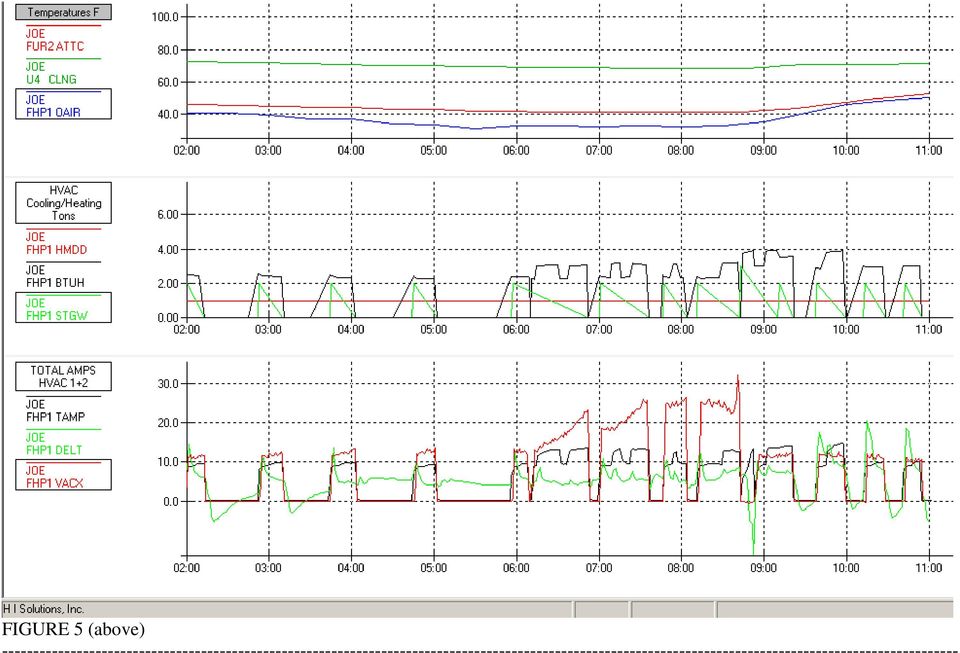
9 resulting in less pressure drop through the coil. In the graph below, OAIR is outside air temp, BTUH is computed Heat Pump capacity in the selected Low/High mode, DELT is the outside evaporator coil temperature difference and VAC is the pressure drop across the outside evaporator coil in inches x 100. (VAC=10 indicates 0.10" pressure drop across outside coil.), TAMP is the total amps drawn by the fan and compressor in the heat pump unit. Note: A defrost cycle occurred when TAMP shows the compressor is running and VAC is zero showing the outside fan is NOT running as in figure 5 at about 8:50AM.
, TAMP is the total amps drawn by the fan and compressor in the heat pump unit.")
10 FIGURE 4 (above) In the figure 4, note that over this 12 hour period where the outside coil temperature was frequently below freezing for short periods (and the Carrier algorithm would have run about 4 defrost cycles), the new algorithm did not call for a defrost even once. Note also that the pressure drop never got above about 0.12" during the period and there was no drop off in TAMPs such as you see with the capacity reduction which accompanies a freeze up situation. This was a situation where there was a) medium humidity, and b) the normal heat pump shutoffs at frequent intervals allowed some defrosting to occur at intervals without running a machine defrost cycle. Another phenomena demonstrated by the above graph is the value of good home insulation. Note that the Outside Air Temperature (OAIR) was down to about 37⁰F at 23:00hours. But the system continued its cycling on/off at a pretty steady duty cycle until about 04:00 when you notice the first transition of BTUH above the LOW capacity during the night. Starting at 06:00 the system goes to high capacity and stays there for 1.5 hours. Then at 08:00, the family room is "turned on" and the system then runs in HIGH capacity for several more hours. During this sequence, I locked out the auxiliary gas heat so the overall effectiveness of the 48,000btu heat pump in the home (all rooms set to occupied) could be evaluated. As shown in the graph, the actual heat pump output at 35⁰F outside was in the range of 37,000btu/h during the night In figure 5 below, Notice that there was obviously increasing icing of the outside coil from about 6AM. However the icing only got the pressure drop across the outside coil to 0.35" (red VAC graph line) at about 8:45AM and so there was only one defrost cycle during the entire night with the temperature below 40⁰F for the entire period. The OEM carrier defrost algorithm would have caused a defrost cycle about four times. It is interesting to note the DELT (green) curve in the lower curves of figures 5 and 6. It can be seen that when significant icing is occurring, the value of DELT stays POSITIVE during the normal heat pump compressor OFF cycle. But if there is no significant icing, the value of DELT reverses and goes negative during the OFF cycle. This results because with little or no icing, the small amount of heat left contained in remnants of the refrigerant in the inside condenser coil moves outside to the colder evaporator coil and is enough to heat up the outside coil to above outside ambient temperatures between cycles unless significant ice is present.
 medium humidity, and b) the normal heat pump shutoffs at frequent intervals allowed some defrosting to occur at intervals without running a machine defrost")
11 FIGURE 5 (above)
12 The image in figure 6 below shows another night when the temperature hovered around freezing. Note that from about 5AM the temperature was around 35⁰F and there was a lot of running of the heat pump from 6AM until 9AM. Yet, not a single defrost cycle was requested by the new algorithm and none was needed. The OEM Carrier Algorithm called for 3 defrost cycles during this interval. Note the multiple momentary power failures at about 5:20AM. These had no effect on the operation of the new algorithm. But the OEM Carrier Algorithm would have reset the defrost timer to 30 minutes as a result of the power fail and this would have perhaps generated a fourth defrost cycle in the Carrier OEM defrost algorithm for this period. FIGURE 6 (above)

13 The figure below shows a sustained period when the outside temperature was between 33⁰F and 38⁰F. The humidity was in the range of 70% so there was not as much icing as you might expect in that temperature range. However, between 6AM and we do see the red VAC curve arch up to a maximum pressure drop of about 15 (0.15"). The graph shows that on this day there was no defrost cycle called for. The OEM carrier defrost cycle algorithm would have called for a defrost 2 or 3 times during this interval. The BTUH curve shows that the system was alternating between the low and high output modes in the 6AM to 8AM period finally going to high output mode continuously at about 8:30AM. At about 8:30am, there is a small "pip" on the STGW up to stage 3 and BTUH graphs indicating that, for a few minutes, auxiliary gas heat was turned on FIGURE 7 (above)

14 In Figure 8 (below) is shown another near freezing night without even one defrosts cycle being called. The OEM algorithm would have called for 2 or 3 defrost cycles during this interval. Note, that the upper group of graphs has been changed to include Outside Humidity, Supply Air Temperature as well as Outside Air Temperature. Again, note the multiple changes from low to high heat pump capacity as shown in the BTUH and TAMP graphs. The STGW graph should be ignored as my data collection equation was not operating properly. FIGURE 8 (above)

15 In Figure 9 (below) we see a night when the temperature went to freezing at about 4AM and stayed there until about 9AM. Only one defrost cycle was called for and that was at about 9:10AM when the air pressure drop across the outside coil finally made it to 0.35". By comparison, the OEM Carrier algorithm called for defrosts three times. FIGURE 9 (above) Figure 10, below, shows Heat Pump operation on a day when the minimum temperature was 20⁰F and the maximum was 28⁰F. Note that the humidity on this day was below 80% and that NO DEFROST CYCLES were required or run. During the night,
 Figure 10, below, shows Heat Pump operation on a day when the minimum temperature was 20⁰F and the maximum was 28⁰F.")
16 the heat pump mostly ran in "low" heating mode only going to "high" heat mode after 6AM as the living quarters zones were turned on. Note also that the heat pump ran continuously for more than 5 1/2 hours from 6:30AM without any appreciable VAC pressure drop across the outside evaporator and was producing between 2.5 and 3.0 tons (30,000 to 36,000BTU/h) of heating during this period. The standard carrier algorithm a) would have defrosted probably 4 times during this interval and would not have allowed operation below about 32⁰F. This is a dramatic showing of the improvement in operation of the new heat pump defrost control scheme. Note also the green curve of STGW. This shows that the auxiliary heat (STGW=3) came on for only two short periods during the night but it did run pretty continuously from 7:45am through 10:15am adding 45,000btuh to the heat pump's 30,000+ BTU/h. Note also that the 90,000BTU/h supplemental furnace (STGW=4) never came on line. FIGURE 10 (above)
 would have defrosted probably 4 times during this interval and would not have allowed operation below about 32⁰F.")
17 Figure 11 (below) shows a full day of operation of the heat pump system with the temperatures ranging from about 13⁰F up to a high of 40⁰F. Note that from the time the temperature went below 20⁰F the system switched over to the backup (natural gas) furnaces. But except for that period from about 2AM until 10AM the heat pump was running and almost continuously and without any sign of a freeze-up as shown by the VAC reading staying in the normal range of just about.11" to.13". The evidence is becoming pretty strong that whenever the humidity is below about 80% or so, defrost cycles are seldom needed. Even above 80% RH, the number of defrost cycles used by the Time + Temperature algorithm vs. the Pressure Difference used here is about 5 to 1. This is more (and pretty conclusive) evidence that the time + temperature defrost algorithm used by Carrier and most other manufacturers is causing MANY MANY wasted defrost cycles. This graph Figure 11 also demonstrates that the heat pump provides useful heat output of about 2.5 tons (30,000btu) all the way down to 20⁰F. Unfortunately, in this case, the amount of heat required to maintain "balance" at 20⁰F is about 80,000BTU/H and so at 20⁰F the switch had to be made automatically from the 30,000 BTU/H Heat Pump + 48,000 BTU/H NG to the 90,000BTU/H NG + the 48,000BTUH NG.

18 FIGURE 11 (above)

19 Figure 12 (below) shows another interesting characteristic of the icing of the outside evaporator. This scatter plot has data on Outside Humidity as the Horizontal Axis and Intensity of occurrences of VACuum measurements (differential pressure across the outside air coil) on the vertical axis. This data was accumulated over the period from mid November to 5 January Notice that ALL of the significant icing (as indicated by red dots above VAC= 12) of the outside heat pump coil has occurred when the outside HUMIDITY was greater than 85%. Below this humidity level, no significant icing occurred at any outside air temperature between 20⁰F and 40⁰F. During this period, the heat pump was run for up to 6 hours continuously in temperatures from 20⁰F to 40⁰F. I consider this factor very significant as it is another measurable parameter that could be used in a decision process as to when defrosting of the Heat Pump outside coil is necessary. This is vivid evidence that the current time + temperature algorithms are causing the World's Heat Pumps to enter the defrost cycle FAR too frequently. FIGURE 12 (above) Questions? Contact joe@mehaffey.us
 of the outside heat pump coil has occurred when the outside HUMIDITY was greater than 85%.")
HEAT PUMP FREQUENTLY ASKED QUESTIONS HEAT PUMP OUTDOOR UNIT ICED-UP DURING COLD WEATHER:
 HEAT PUMP FREQUENTLY ASKED QUESTIONS HEAT PUMP OUTDOOR UNIT ICED-UP DURING COLD WEATHER: It is normal for a heat pump to have a build up of white frost on the outside coil during cold damp weather. The
Glossary of Heating, Ventilation and Air Conditioning Terms
 Glossary of Heating, Ventilation and Air Conditioning Terms Air Change: Unlike re-circulated air, this is the total air required to completely replace the air in a room or building. Air Conditioner: Equipment
Hybrid (Dual Fuel) - Gas Heat and Air Source Heat Pump
 - Gas Heat and Air Source Heat Pump") s.doty 10-2014 White Paper #30 Hybrid (Dual Fuel) - Gas Heat and Air Source Heat Pump System Switches Fuels Automatically for Economy. What is an Air-Source Heat Pump? A heat pump is a modified air conditioning
s.doty 10-2014 White Paper #30 Hybrid (Dual Fuel) - Gas Heat and Air Source Heat Pump System Switches Fuels Automatically for Economy. What is an Air-Source Heat Pump? A heat pump is a modified air conditioning
Creating Efficient HVAC Systems
 Creating Efficient HVAC Systems Heating and Cooling Fundamentals for Commercial Buildings Heating, ventilating, and air conditioning (HVAC) systems account for nearly half of the energy used in a typical
Installation Questions
 Installation Questions How do I determine what type of heat I have? There may be several ways to determine what type of heat you have. First, if you can access the unit that is responsible for creating
Variable Air Volume - VAV
 Mode Enable Sensor Options Variable Air Volume - VAV The temperature of this sensor will determine if the unit is in heating, cooling or vent mode during occupied operation. The following options are available:
Indoor coil is too warm in cooling mode or too cold in heating mode. Reversing valve or coil thermistor is faulty
 Codes Room Air Conditioner range: Indoor unit alarm s If timer lamp flashes for 1 second on, 1 second off, this indicates pre heating on the coil during heating mode and is not an error. If timer lamp
SECTION 23 81 03 - PACKAGED ROOFTOP AIR CONDITIONING UNITS NON-CUSTOM
 SECTION 23 81 03 - PACKAGED ROOFTOP AIR CONDITIONING UNITS NON-CUSTOM PART 1 - GENERAL 1.1 SUMMARY A. Section Includes: 1. Packaged rooftop air conditioning unit (5 tons and smaller). 2. Roof curb. 1.2
Failure code manual. content
 Failure code manual content 一 wall split AC series 2 二 floor standing AC series. 4 三 portable AC series.. 5 四 dehumidifer 6 五 DC inverter single split series...7 六 DC inverter multi-split series 10 1 一
It will be available soon as an 8.5 X 11 paperback. For easier navigation through the e book, use the table of contents.
 The System Evaluation Manual and Chiller Evaluation Manual have been revised and combined into this new book; the Air Conditioning and Refrigeration System Evaluation Guide. It will be available soon as
Air-Conditioning Buying Guide
 Air-Conditioning Buying Guide Buying a new air-conditioning system is a big decision. This Air-Conditioning Buying Guide can help you make the right choice, save energy and money. Shop with confidence
REMOTE CONTROL MANUAL
 REMOTE CONTROL MANUAL ENGLISH CONTENT PRECAUTIONS...1-2 USING THE REMOTE CONTROL UNIT...3 OPERATION...4-9 Thank you for purchasing our Room Air Conditioner. Before using your air-conditioner, please read
HEATING AND COOLING SYSTEMS THAT FIT COMFORTABLY WITHIN YOUR BUDGET.
 HEATING AND COOLING SYSTEMS THAT FIT COMFORTABLY WITHIN YOUR BUDGET. AFFORDABLE SOLUTIONS FROM AMERISTAR. We know that heating and cooling systems can be a major investment for homeowners. Our goal is
1932 Lexington Houston, Texas 77098-4220 (713) 524-4877. Recommendations for installation of cooling systems
 524-4877. Recommendations for installation of cooling systems") 1932 Lexington Houston, Texas 77098-4220 (713) 524-4877 The purpose for this information is to provide a better understanding of the HVAC equipment, components, designs, and installations, of HVAC system
1932 Lexington Houston, Texas 77098-4220 (713) 524-4877 The purpose for this information is to provide a better understanding of the HVAC equipment, components, designs, and installations, of HVAC system
USER S MANUAL HSC-24A
 AIRREX AIR CONDITIONER USER S MANUAL HSC-24A Thank you for purchasing an AIRREX AIR CONDITIONER. BEFORE operation please read this user s manual carefully. Keep this manual readily available. It is ESSENTIAL
SECTION 23 81 43 HEAT PUMPS
 SECTION 23 81 43 HEAT PUMPS PART 1 GENERAL 1.1 SUMMARY A. Section Includes: 1. Packaged rooftop heat pumps. 1.2 REFERENCES A. American Society of Heating, Refrigerating and Air-Conditioning Engineers:
How to choose a heat pump and use it wisely
 How to choose a heat pump and use it wisely Contents How does a heat pump work? 2 Insulating your home 3 Heat loss in the home Not all heat pumps are created equal 4 Choosing a heat pump 4 Choosing by
Air Conditioning. The opportunity for energy efficiency. Low cost actions to reduce energy usage now
 Fact Sheet #6 Air Conditioning In this fact sheet you will discover: The opportunity for energy efficiency How air conditioning works Low cost actions to reduce energy usage now Investments to reduce costs
Presentation Outline. Common Terms / Concepts HVAC Building Blocks. Links. Plant Level Building Blocks. Air Distribution Building Blocks
 Presentation Outline Common Terms / Concepts HVAC Building Blocks Plant Level Building Blocks Description / Application Data Green opportunities Selection Criteria Air Distribution Building Blocks same
Combination Ductless Heat Pump & Heat Pump Water Heater Lab and Field Tests
 August 26, 2015 REPORT #E15-294 Combination Ductless Heat Pump & Heat Pump Water Heater Lab and Field Tests Prepared by: Energy 350 107 SE Washington St., Suite 145 Portland, OR 97214 Northwest Energy
Single Zone LCD Thermostat Operating Instructions
 Fan Cool Furnace *Heat Pump or Heat Strip On/Off F Single Zone LCD Thermostat Operating Instructions MODEL 3313192.XXX Cool/Furnace 3313193.XXX Cool/Furnace/Heat Pump 3313194.XXX Cool/Furnace/Heat Strip
Dehumidification Frequently Asked Questions
 Dehumidification Basics Why do you want to keep indoor Rh between 30-60%? ASHRAE recommends keeping the relative humidity in a home between 30-60% to limit the effects of many unwanted conditions and harmful
Get the FACTS about SEER and Deliver Better Customer Value
 What is SEER? SEER stands for Seasonal Energy Efficiency Ratio. It s a number that describes how well air-conditioning equipment works. A higher SEER means better efficiency and lower energy bills. SEER
Refrigeration Basics 101. By: Eric Nelson
 Refrigeration Basics 101 By: Eric Nelson Basics Refrigeration is the removal of heat from a material or space, so that it s temperature is lower than that of it s surroundings. When refrigerant absorbs
Heating and Cooling Basics Thermostat Control
 Heating and Cooling Basics Thermostat Control UNI-LINE PRODUCT KNOWLEDGE 2012 Invensys. All Rights Reserved. The names, logos, and taglines identifying the products and services of Invensys are proprietary
PANASONIC TROUBLE SHOOTING GUIDE
 A General Guide To Room Style Products Pipework Pipe sizes and lengths should be as the relevant Technical Guide Both lines should be insulated No line accessories or oil traps should be fitted In cooling
HVAC Efficiency Definitions
 HVAC Efficiency Definitions Term page EER - 2 SEER - 3 COP - 4 HSPF - 5 IPLV - 6 John Mix May 2006 Carrier Corporation 1 Energy Efficiency Ratio (EER) The energy efficiency ratio is used to evaluate the
Introduction. Motor Types
 QwikSEER+ Theory of Operation and Retrofit Potential Mainstream Engineering Corporation Rockledge, FL 32955 http://www.qwik.com/products/qwikseer/index.jsp Prepared by Robert P. Scaringe and R. Paul Roth
GEOTHERMAL HEATING AND COOLING INTRODUCTION
 GEOTHERMAL HEATING AND COOLING INTRODUCTION Geothermal Heating and Cooling Systems provide space conditioning -- heating, cooling, and humidity control. They may also provide water heating -- either to
New Deluxe Wall Mounted Heat Pump Series EXTERIOS
 New Deluxe Wall Mounted Heat Pump Series EXTERIOS May 2013 New Deluxe Wall Mounted Heat Pump Series Panasonic Adding New Air Conditioner Lineup Setting Another Mile Stone in the US Ductless Split History
Programmable Thermostat MODEL 3312026.XXX With Dehumidify 3312024.XXX With Out Dehumidify
 Comfort Control Center 2 Thermostat Operating Instructions Programmable Thermostat MODEL 3312026.XXX With Dehumidify 3312024.XXX With Out Dehumidify TABLE OF CONTENTS About your new thermostat Features...2
Any Service Technician Can Fix It A Good Service Technician Can Figure Out What s Wrong With It.
 I Dave s Statement If the thermostat calls for cooling, and the furnace fan is running properly, and the coil airflow is adequate, and the condenser fan is running properly, and the condenser airflow is
Thermostatic Wiring Principles by Bob Scaringe Ph.D., P.E.
 Thermostatic Wiring Principles by Bob Scaringe Ph.D., P.E. Basic Thermostat Types Many technicians have great difficulty understanding how to properly wire a thermostat or how to replace a thermostat with
ASHRAE Boston Chapter Meeting Designing AC Refrigeration Systems Lessons Learned February 11, 2014
 ASHRAE Boston Chapter Meeting Designing AC Refrigeration Systems Lessons Learned February 11, 2014 Explanation of the refrigeration cycle. Compressors. Benefits and operating characteristics. -Reciprocating
Heat Pumps for Cold Climates?? Yes, Indeed!
 Heat Pumps for Cold Climates?? Yes, Indeed! by Bob Zogg, Carlisle Energy Task Force (http://greencarlisle.org) August 26, 2014 This is not your parent s heat pump! The conventional wisdom is that it s
The ASHRAE HQ Building Can the energy efficiency of the different mechanical systems really be compared? RESIDENTIAL LIGHT COMMERCIAL COMMERCIAL
 The ASHRAE HQ Building Can the energy efficiency of the different mechanical systems really be compared? RESIDENTIAL LIGHT COMMERCIAL COMMERCIAL Technical Article April 2013 The ASHRAE HQ Building Can
How To Use A Water Source Heat Pump
 Geothermal Energy Using Water-Source Heat Pumps By VIRSTAR Corporation Geothermal Expertise Since 1978 All information contained herein is the exclusive property of VIRSTAR Corporation, all rights reserved.
Ground Source Heat Pumps The Fundamentals. Southington, Connecticut 860 628 4622 John F. Sima III P.E.
 Ground Source Heat Pumps The Fundamentals Southington, Connecticut 860 628 4622 John F. Sima III P.E. Winter/Spring 2010 Ground Source Heat Pumps The Fundamentals TOPICS: Heat Pump Terminology Basic Physics
Energy savings in commercial refrigeration. Low pressure control
 Energy savings in commercial refrigeration equipment : Low pressure control August 2011/White paper by Christophe Borlein AFF and l IIF-IIR member Make the most of your energy Summary Executive summary
POLICY BULLETIN Tecumseh Compressor Company Compressor Group
 to Bulk Milk Coolers and Other System Page 1 of 5 Overall reliability can be enhanced if there exists a complete understanding of the features, system design, installation requirements, processing, charging
The Benefits Really Add Up
 Unico, Inc. 7401 Alabama Ave. St. Louis, MO 63111 Unico, Inc. manufacturing plant and sub-assembly plant +1 800 527 0896 +1 314 481 9000 www.unicosystem.com Unico, Inc. is the leader in Small Duct High
HP 5 Microprocessor Control for Mammoth Water Source Heat Pumps
 HP 5 Microprocessor Control for Mammoth Water Source Heat Pumps Operation and Maintenance Manual Model: 71028004 Applies to: Single Circuit Water-to-Water Twin Circuit Units Without DDC Controls MAMM WHSP
HVAC Basic Science - System Capacity
 HVAC Basic Science - System Capacity Btu/hour, btu/h, b/h, btuh. btu?? 1 MBH = 1000 btu/hour 1 KBH = 1000 btu/hour 1 ton of cooling= 12,000 btu/hour 1 watt = 3.414 btu/hour 1 kilowatt = 1000 watts = 3,414
RESEARCH HIGHLIGHT. Performance Assessment of a Cold-Climate Air Source Heat Pump
 RESEARCH HIGHLIGHT December 2014 Technical Series 14-102 Performance Assessment of a Cold-Climate Air Source Heat Pump INTRODUCTION Most Canadians are familiar with air source heat pump technology in the
Basic Technology Series
 Basic Technology Series Fundamentals of Car Air Conditioning 2007 Air Conditioning #003 The Rear Cooler Construction Fan Fan Filter Figure A : Trunk Figure B : Overhead Dual Air-Conditioner In This Issue
Tech Byte 27: Small Computer Room and IT Closet Cooling
 Questions Answered in This Paper Sensible cooling capacity is the measuring stick for IT cooling capacity needs. What is the sensible cooling capacity of the comfort split system in comparison to the precision
HVAC Processes. Lecture 7
 HVAC Processes Lecture 7 Targets of Lecture General understanding about HVAC systems: Typical HVAC processes Air handling units, fan coil units, exhaust fans Typical plumbing systems Transfer pumps, sump
Heating & Cooling Efficiency
 Heating & Cooling Efficiency Advantages of Geothermal HVAC Efficiency Keith Swilley Gulf Power Company Why Gulf Power Promotes Energy Efficiency? Customer Satisfaction Education Help Customers Make Smart
QUESTIONS TO ASK WHEN REPLACING YOUR HVAC TOGETHERWESAVE.COM
 QUESTIONS TO ASK WHEN REPLACING YOUR HVAC TOGETHERWESAVE.COM TOGETHERWESAVE.COM IS IT TIME TO REPLACE YOUR HVAC SYSTEM? If your heating and cooling system is 15 to 20 years old and is experiencing problems,
SERVICE MANUAL FOR 6535 SERIES TWO TON HIGH EFFICIENCY PACKAGED HEAT PUMPS
 SERVICE MANUAL FOR 6535 SERIES TWO TON HIGH EFFICIENCY PACKAGED HEAT PUMPS TABLE OF CONTENTS 1. Warnings...2 2. Accessibility Of Appliance...3 3. Unit Dimensions And Specifications...3 4. Unit Specifications
Technical Support Bulletin Nr. 20 Special AC Functions
 Technical Support Bulletin Nr. 20 Special AC Functions Summary! Introduction! Hot Start Control! Adaptive Control! Defrost Start Temperature Compensation Control! Anti-Sticking Control! Water Free Cooling
INSTALLATION AND OPERATION MANUAL
 RCS MODEL ZC4 4 ZONE HVAC INSTALLATION AND OPERATION MANUAL DCN: 141-0020-02 /0/03 INTRODUCTION The 4 Zone HVAC Controller series allows up to 4 standard electronic thermostats to independently control
Zoned Air Conditioners - A Real Value?
 H114 Prepared by: Proctor Engineering Group, Ltd. San Rafael, CA 94901 (415)451-2480 Zoning Ducted Air Conditioners, Heat Pumps, and Furnaces: Summary of a Case Study prepared for the California Statewide
The Development of a Frost-Less Heat Pump
 The Development of a Frost-Less Heat Pump V. C. Mei, R. E. Domitrovic, and F. C. Chen, Oak Ridge National Laboratory J. K. Kilpatrick, Tennessee Valley Authority ABSTRACT There are two major concerns associated
Air Conditioning Sign-Off Sheet
 Air Conditioning Sign-Off Sheet Printed Technician Name Address Social Security Number Telephone Number City State Zip Code Install Or Verify The Accuracy Of An Air Conditioner s Installation The candidate
Gree Solar Hybrid Hi Wall Inverter Air Conditioner
 Gree Solar Hybrid Hi Wall Inverter Air Conditioner Utilize the natural power of the sun to heat or cool your home. Find out more at www.greeonline.com Why Choose a Solar Hybrid Inverter? The new Gree Solar
CONTENTS 1. IMPORTANT NOTICE 2 2. TECHNICAL SPECIFICATION 3 3. OPERATION DETAILS 4 4. ELECTRICAL SCHEMATIC DIAGRAM 13 5. EXPLOSION VIEW 16 6
 TCL WALL MOUNTED SPLIT-TYPE AIR CONDITIONERS SERVICE MANUAL No.TE080528 Models KFTHP-12 KFTHP-18 KFTHP-24 CONTENTS 1. IMPORTANT NOTICE 2 2. TECHNICAL SPECIFICATION 3 3. OPERATION DETAILS 4 4. ELECTRICAL
THERMO KING TRUCK & TRAILER UNIT ALARM CODES THIS DOCUMENT SHOWS ALL CURRENT ALARM CODES FOR THERMO KING TRUCK AND TRAILER UNITS.
 THERMO KING TRUCK & TRAILER UNIT ALARM CODES THIS DOCUMENT SHOWS ALL CURRENT ALARM CODES FOR THERMO KING TRUCK AND TRAILER UNITS. NOT ALL CODES ARE POSSIBLE ON ANY INDIVIDUAL UNIT. IF THE ALARM APPLIES
LG Air Conditioning Multi F(DX) Fault Codes Sheet. Multi Split Units
 Fault Codes Sheet. Multi Split Units") Multi Split Units If there is a fault on any LG Multi unit, an Error mark is indicated on the display window of the indoor unit, wired-remote controller, and LED s of outdoor unit control board. A two
Multi Split Units If there is a fault on any LG Multi unit, an Error mark is indicated on the display window of the indoor unit, wired-remote controller, and LED s of outdoor unit control board. A two
Air Conditioner Water Heater - A Product of HotSpot Energy LLC
 Air Conditioner Water Heater - A Product of HotSpot Energy LLC PLEASE READ THIS BEFORE YOU INSTALL THE UNIT 1. This air conditioner must be installed and/or repaired by a qualified technician. If you perform
AIR CONDITIONING EFFICIENCY F8 Energy eco-efficiency opportunities in Queensland Foundries
 AIR CONDITIONING EFFICIENCY F8 Energy eco-efficiency opportunities in Queensland Foundries Hot tips and cool ideas to save energy and money! Air conditioning units or systems are often used by foundries
How To Make A High Efficiency Thermostat
 Zoning with Variable Speed Mini-Split Systems Fujitsu Service Training Welcome - Thank you for attending Did you know? In 1940 only 42% of homes in the US had central heating In 1970 20% of homes had central
CONTENTS 1. IMPORTANT NOTICE 2 2. TECHNICAL SPECIFICATION 3 3. OPERATION DETAILS 4 4. WIRING DIAGRAM 11 5. EXPLOSION VIEW 12 6.
 TCL WALL MOUNTED SPLIT-TYPE AIR CONDITIONERS SERVICE MANUAL No.TE051220 Models TAC-09CHSA/GI TAC-12CHSA/GI CONTENTS 1. IMPORTANT NOTICE 2 2. TECHNICAL SPECIFICATION 3 3. OPERATION DETAILS 4 4. WIRING DIAGRAM
February 1, 2006. Performance Tested Comfort Systems Air Source Heating Pump Installation Commissioning Procedure
 February 1, 2006 Performance Tested Comfort Systems Air Source Heating Pump Installation Commissioning Procedure Overview - Several measurements of air source heat pump system performance are required
SERVICE MANUAL 12VDC WALL THERMOSTAT AIR CONDITIONING SYSTEMS ROOFTOP UNITS ONLY
 SERVICE MANUAL 12VDC WALL THERMOSTAT AIR CONDITIONING SYSTEMS ROOFTOP UNITS ONLY! WARNING - SHOCK HAZARD! TO PREVENT THE POSSIBILITY OF SEVERE PERSONAL INJURY, DEATH, OR EQUIPMENT DAMAGE DUE TO ELECTRICAL
T-100-R Installation Guide
 T-100-R Installation Guide Table of Contents Page 2 Overview T-100-R Z-Wave Thermostat 3-4 Installation HVAC System Setup 6 Installer Settings Menu Items 7-9 Installer Settings Summary 10-11 Wiring Standard
The Only GUY To Call. Why are my utility bills so high? What can I do to lower my energy expenses?
 The Only GUY To Call May 2014 412.885.2356 Why are my utility bills so high? What can I do to lower my energy expenses? Did you know... that between 2007 and 2012, the average U.S. household spent more
SMM. Installation Operation Maintenance
 SMM Configuration SMM Module for Scroll Units, H Generation Installation Operation Maintenance 1 0 L80 IM 022 GB SMM Configuration SMM Module for Scroll Units, H generation Foreword These installation,
Why and How we Use Capacity Control
 Why and How we Use Capacity Control On refrigeration and air conditioning applications where the load may vary over a wide range, due to lighting, occupancy, product loading, ambient weather variations,
SERVICE INSTRUCTION R410A. WALL MOUNTEDtype INVERTER SPLIT TYPE ROOM AIR CONDITIONER. Models Indoor unit Outdoor unit
 SERVICE INSTRUCTION SPLIT TYPE ROOM AIR CONDITIONER WALL MOUNTEDtype INVERTER Models Indoor unit Outdoor unit ASYG07LECA ASYG09LECA ASYG12LECA ASYG14LECA AOYG07LEC AOYG09LEC AOYG12LEC AOYG14LEC R410A CONTENTS
Fossil fuel heating equipment
 Fossil fuel heating equipment principles and troubleshooting techniques Application Note This application note was written to provide you with an understanding of the basic principles of fossil fuel heating
USER S GUIDE For all Packaged Systems (Air Conditioners and Heat Pumps)
") USER S GUIDE For all Packaged Systems (Air Conditioners and Heat Pumps) WA & WL - Series Air Conditioners WH & SH - Series Air Source Heat Pumps IH - Series Air Source Heat Pumps DATE: 02-21-12 QA - Series
USER S GUIDE For all Packaged Systems (Air Conditioners and Heat Pumps) WA & WL - Series Air Conditioners WH & SH - Series Air Source Heat Pumps IH - Series Air Source Heat Pumps DATE: 02-21-12 QA - Series
SERVICE INSTRUCTION R410A. SPLIT TYPE ROOM AIR CONDITIONER Universal Floor / Ceiling Duct / Cassette Wall Mounted / Floor type INVERTER MULTI
 SERVICE INSTRUCTION SPLIT TYPE ROOM AIR CONDITIONER Universal Floor / Ceiling Duct / Cassette Wall Mounted / Floor type INVERTER MULTI R410A Models Indoor unit Outdoor unit AB*14LBAJ AB*18LBAJ AB*F14LAT
How To Improve Energy Efficiency Through Raising Inlet Temperatures
 Data Center Operating Cost Savings Realized by Air Flow Management and Increased Rack Inlet Temperatures William Seeber Stephen Seeber Mid Atlantic Infrared Services, Inc. 5309 Mohican Road Bethesda, MD
543-0032-00, 943-0032-00. User s Manual
 543-0032-00, 943-0032-00 User s Manual 1 Comfort Alert Diagnostics Faster Service And Improved Accuracy The Comfort Alert diagnostics module is a breakthrough innovation for troubleshooting heat pump and
Energy Efficiency. Energy Efficient Home Cooling:
 Energy Efficiency Energy Efficient Home Cooling: Choosing an air conditioning system is an important decision. A poor choice may be costly to purchase and operate and yet fail to provide the desired cooling
Analysis of data centre cooling energy efficiency
 Analysis of data centre cooling energy efficiency An analysis of the distribution of energy overheads in the data centre and the relationship between economiser hours and chiller efficiency Liam Newcombe
The XP17 provides comfort without comparison.
 ideal The XP17 provides comfort without comparison. Catching those quick moments to relax with your favorite person is a cherished privilege that shouldn t be affected by the air around you. The XP17 from
Performance Evaluation of a Heat Pump System for Simultaneous Heating and Cooling
 for Simultaneous Heating and Cooling F. Sustainable Energy Centre, University of South Australia Mawson Lakes Boulevard, Mawson Lakes 5095 AUSTRALIA E-mail: Frank.@UniSA.edu.au Abstract The high efficiency
ZUBA-CENTRALTM. Heating & Cooling. Evolved. HEATING AND AIR CONDITIONING FOR WHOLE-HOME, YEAR-ROUND COMFORT
 ZUBA-CENTRALTM Heating & Cooling. Evolved. HEATING AND AIR CONDITIONING FOR WHOLE-HOME, YEAR-ROUND COMFORT Energy-efficient. Easy to install. Extremely quiet. Zuba-Central is simply the new and better
How To Understand Evaporator
 SECTION 5 COMMERCIAL REFRIGERATION UNIT 21 EVAPORATORS AND THE REFRIGERATION SYSTEM UNIT OBJECTIVES After studying this unit, the reader should be able to Define high-, medium-, and low-temperature refrigeration.
 AIR COOLED CHILLER CHILLED WATER PUMP CONTROL: The chilled water pump with the lowest runtime will automatically start when the outside air temperature rises above the system enable setpoint. When the
Development of Air-to-Water Heat Pump for Home Air conditioning/hot Water Supply Combination System with Chilled/Hot Water in European Markets
 2 Development of Air-to-Water Heat Pump for Home Air conditioning/hot Water Supply Combination System with Chilled/Hot Water in European Markets - Extending Use of New Heat Pump System in Cold Regions
HVAC System Cloud Based Diagnostics Model
 2496, Page 1 HVAC System Cloud Based Diagnostics Model Fadi ALSALEEM 1*, Robert ABIPROJO 2, Jeff ARENSMEIER 2, Gregg HEMMELGARN 1, 1 Emerson Climate Technologies, Residential Solutions, Sidney, OH, USA
Fuel and Energy Conversion and Equivalence Chart
 Fuel and Energy Conversion and Equivalence Chart Please note, the fuel economy estimates within this document are examples only. Maine Public Service does not consult with customers regarding fuel source
HVAC Systems: Overview
 HVAC Systems: Overview Michael J. Brandemuehl, Ph.D, P.E. University of Colorado Boulder, CO, USA Overview System Description Secondary HVAC Systems Air distribution Room diffusers and air terminals Duct
its ELECTRIC POSITION for electric heat, or set the units fan control appropriately to ELECTRIC or another appropriate setting.
 Troubleshooting Poor Temperature Regulation This page lists problems that may affect the temperature performance of your LUX thermostat with suggested resolutions. For more detailed information please
Optimization of Water - Cooled Chiller Cooling Tower Combinations
 Optimization of Water - Cooled Chiller Cooling Tower Combinations by: James W. Furlong & Frank T. Morrison Baltimore Aircoil Company The warm water leaving the chilled water coils is pumped to the evaporator
USER MANUAL WARNING! CONTENTS MODEL 1 SPECIFICATIONS READ ALL INSTRUCTIONS BEFORE PROCEEDING. Non-Programmable Single Stage Heat/Cool Thermostat
 Builder MODEL 1010 Series Non-Programmable Single Stage Heat/Cool Thermostat USER MANUAL Compatible with low voltage single stage gas, oil or electric heating or cooling systems, including single stage
SECTION 15750 PACKAGED ROOFTOP AIR CONDITIONING UNITS
 SECTION 15750 PART 1 - GENERAL 1.01 DESCRIPTION A. Section includes requirements for roof mounted, self-contained units, with electric cooling, and electric or reverse refrigeration cycle (heat pump) heating
Environmental Data Center Management and Monitoring
 2013 Raritan Inc. Table of Contents Introduction Page 3 Sensor Design Considerations Page 3 Temperature and Humidity Sensors Page 4 Airflow Sensor Page 6 Differential Air Pressure Sensor Page 6 Water Sensor
C-Bus Application Messages & Behaviour Chapter 25 Air Conditioning
 C-Bus Application Messages & Behaviour Chapter 25 Air Conditioning Document Number: CBUS-APP/25 Comments on this document should be addressed to: Engineering Manager Clipsal Integrated Systems PO Box 103
Chilled Water HVAC Systems
 Chilled Water HVAC Systems By Ron Prager, Brinco Mechanical Services, Inc. Types of water based systems: There are three types of HVAC systems that utilize water as a heat transfer medium. The first system,
Ener.co & Viridian Energy & Env. Using Data Loggers to Improve Chilled Water Plant Efficiency. Randy Mead, C.E.M, CMVP
 Ener.co & Viridian Energy & Env. Using Data Loggers to Improve Chilled Water Plant Efficiency Randy Mead, C.E.M, CMVP Introduction Chilled water plant efficiency refers to the total electrical energy it
Poor Performing AC? High Electric Bills? High Humidity?
 Poor Performing AC? High Electric Bills? High Humidity? If you answered yes to any or all of these questions, it may be time to consider a new Air Conditioning system. Read on for useful information when
HVAC Simplified Approach Option
 HVAC Simplified Approach Option Part I Project Address: City: HVAC System Designer of Record: Date: Zip: Qualification The building is 2 stories or less in height and has a gross floor area is less than
14. Troubleshooting Guide
 14. Guide 14.1 Refrigeration Cycle System In order to diagnose malfunctions, ensure the air conditioner is free from electrical problems before inspecting the refrigeration cycle. Such problems include
How To Save Energy With High Pressure Control
 Energy savings in commercial refrigeration equipment : High Pressure Control July 2011/White paper by Christophe Borlein AFF and IIF-IIR member Make the most of your energy Summary Executive summary I
Heating Ventilation and Air Conditioning Diagnostics for Single Family Homes
 Heating Ventilation and Air Conditioning Diagnostics for Single Family Homes Vincent Pedalino FSL Home Improvements Phoenix, AZ 1 HVAC Basics Ways to improve the performance of existing air conditioning
How much do you know about HVAC? Try testing yourself with the following questions and then take a look at the answers on the following page.
 Demystifying HVAC Test Your HVAC Knowledge By Ron Prager How much do you know about HVAC? Try testing yourself with the following questions and then take a look at the answers on the following page. 1)