Improved Life for Dynamic Seals in Wind Turbine Applications
|
|
|
- Abner McDonald
- 8 years ago
- Views:
Transcription
1 Improved Life for Dynamic Seals in Wind Turbine Applications By Elizabeth Chitren - Product Engineer, Klozure Dynamic Seals, Palmyra, NY Jim Drago, P.E. - Manager, Engineering, Garlock Sealing Technologies, Palmyra, NY Presented at WindPower 2005 Conference and Exhibition May 15-18, 2005 Denver, Colorado Updated March 14, 2008 Abstract The wind power industry desires components that will last 20 years. Contact type rubber lip seals cannot offer this life. Non-contacting isolator seals made of PTFE or metal can offer this possibility since there are no contacting parts. This paper presents the background, working parameters, typical applications and pros and cons of rubber lip and isolator seals. Laboratory data shows the decrease of power consumption when isolators are used. Field data shows the increase in life offered by isolators over rubber lip seals. WindPower 2005 Page 1 of 21

2 Introduction Seals are components thought little of, until leaks occur causing costly down time and repairs. Dynamic seals for rotating shafts, found in the gearbox, generator, pitch and yaw systems of a wind turbine, play important roles by retaining lubricant for bearings and excluding contaminants that will destroy bearings. Seals also protect the remote environments that are the homes of many wind farms. Good seals and sealing practices protect these environments from unwanted lubricant leakage and spills. Low cost components, such as seals, can have major effects on the duration between the repair of major components such as turbine gearboxes, generators, auxiliary motors, and gears. Rubber lip seals have traditionally been used to protect these costly components. It has been assumed that rubber lip seals will perform the service cycles required. The wind industry's goal has been to attain 20 years of service before major maintenance is required. Traditional rubber lip seals rub on a rotating shaft to achieve the required seal. The normal life progression of a lip seal is to wear, leak, then be replaced. Non-contacting isolators do not depend on rubbing contact to contain lubricant and keep out destructive contaminants. With no wearing parts they can theoretically last forever. This paper sets forth: The background on rubber lip seals and isolators A comparison of rubber lip seal and isolator attributes and performance Power consumption of rubber lip seals versus isolators Field experiences and life expectations New developments in the field of large diameter isolators WindPower 2005 Page 2 of 21

3 Background Information on Rubber Lip Seals and Isolator Seals The purpose of a sealing system in a wind turbine is to prevent the damage of bearing elements. To prevent bearing damage, the sealing system must eliminate cross-contamination between the system lubricant and the external environment. Simply, the purpose of the sealing system is to prevent both lubrication egress and contamination ingress. Traditionally, this system has been a lip seal running on a shaft. However, new technologies have made labyrinth isolator seals a possibility in these hostile environments. Lip Seal Background To effectively protect the bearings in a wind turbine, a leak-tight sealing system must be established. Creating an effective seal requires attention to three components: the lip seal, the system lubricant, and the rotating shaft's surface. The lip seal incorporates interacting design features to attain an effective seal. Figure 1 and Table 1 identify these design features. Figure 1 Lip Seal Design Features Table 1 The seal surface is the interface between the lip seal and the shaft-sealing surface. This is where the main seal is formed. The lip angle on the lubricant side is engineered to develop hydrodynamic pressure to facilitate sealing. The lip angle on the environmental side is used to control the amount of lubrication allowed under the lip. The seal hinge location controls the lip deflection and aids in the loading of the lip seal on the shaft. The spring position controls the amount and location of the lip load relative to the shaft-sealing surface. The internal diametric interference between the lip and the shaft interacts with the spring to create the seal force on the sealing surface. The external diametric interference between the outside diameter and the housing prevents leakage around the outside of the seal. Collectively these features act to create an effective seal WindPower 2005 Page 3 of 21

4 Shaft Seal Surface and Its Affect on Performance The performance of the seal can be compromised by the condition of the shaft-sealing surface. Seal manufacturers as well as organizations such as the Rubber Manufacturers Association (RMA) publish specifications for this surface. Imperfections on any surface will always exist. Accepted specifications mitigate imperfections by specifying surface roughness (expressed as average height in micro-inches, Ra), surface lay (texture) and machining methods. An example of the imperfections on a machined surface is shown in Figure 2. Figure 2 Shaft Surface Finish It is important to note that the smoothest surface may not be the optimal surface for lip seals. The small surface imperfections actually aid in sealing. These imperfections, when rotating, will create a small hydrodynamic pump. Another important aspect to consider when machining the sealing surface is the lay of the finish. When creating the sealing surface, the surface lay must be perpendicular to the axis of rotation. The resulting peaks and valleys will act as leakage barriers. WindPower 2005 Page 4 of 21

5 As the shaft continues to rotate, the seal will begin to mirror the surface on which it is running. If the surface lay is parallel to the axis of rotation, it will create a direct leak path. Machining practices must also be considered when fabricating a sealing surface. As the rotating surface is machined, a screw-like trench will be created. This feature will pump the lubricant out of the seal. For this reason, a plunge ground surface finish is usually recommended by seal manufacturers. When all these factors are within specification for a given lip seal, a small viscous pump is created while the shaft is rotating. This hydrodynamic pumping action is created when the small asperities on the seal lip and the surface of the shaft start to displace lubrication, in a steady and regular direction. Figure 3 is a picture of the asperities and lubrication during the hydrodynamic pumping. Figure 3 Asperities on Seal Lip In order to have a long-lasting sealing system, these factors must be kept in balance. If any of these factors are less than optimal, the life of the sealing system will be compromised. Isolator Seal Background Unlike lip seals, isolator seals are simple in theory. By definition, an isolator is a non-contacting seal that prevents oil from exiting the bearing housing and prevents contamination from entering the bearing housing. There are many types of isolators, from labyrinth type seals to complex hybrid designs. These hybrid seals are a combination of new technologies with standard labyrinth technologies. New technologies include hydrodynamic pumping features, cellular foams, and unique unitizing elements. These hybrid seals are typically used in applications where standard technologies will not perform for an extended period of time. WindPower 2005 Page 5 of 21

6 Standard Labyrinth Isolator A standard labyrinth type seal uses a torturous path and close clearances to prevent leakage. This torturous path is usually an intricate pathway with abrupt directional changes. An example of this is shown in Figure 4. Figure 4 Typical Isolator Labyrinth Seal Hybrid Isolators One type of hybrid isolator seal technology uses unique impeller features on the rotor to create a hydrodynamic pumping action. This type of seal can be seen in Figure 5. As the rotor spins, a negative pressure is generated on the outside portion of the lubrication and environment chambers. The negative pressure on the lubrication side causes any lubricant that enters the seal to flow from the shaft to the expulsion ports. The negative pressure on the environment side allows any contamination that enters the seal to flow from the shaft to the expulsion ports. Crosscontamination is mitigated by the labyrinth path between the two systems. Figure 5 Hydrodynamic Isolator In the seal shown in Figure 6, cellular foam is used with standard labyrinth technology to prevent contamination of the bearing. The cellular foam filters out any airborne particulate. It also prevents lubrication leakage by absorbing the fluid into the material. While the foam does have limited capacity, once full, effective sealing will still occur, as the foam will act as a barrier. The type of cellular foam used is application specific, based on the viscosity of the fluid and on the particulate size of environmental contamination. In addition to the cellular foam, designs typically include a labyrinth path to prevent cross-contamination. WindPower 2005 Page 6 of 21

7 Figure 6 Cellular Foam Hybrid Seal Figure 7 is a hybrid labyrinth seal, in which a unitizing element keeps the assembly together. A common misconception is that the unitizing element creates a seal. The isolator actually uses the labyrinth path to prevent contamination ingress, and lubrication egress. The unitizing element simply prevents the rotor and stator from coming into contact with one another during operation, which prevents the generation of damaging particles. If contact were made between the two main components, the particles could contaminate the lubrication system and eventually lead to premature bearing failure. Figure 7 Hybrid Labyrinth Seal New Technologies As stated previously, there is now a wide variety of bearing isolators to choose from. These seals are now offered in a wide variety of material combinations, and in many different styles. A common challenge of isolator seal applications is the axial space required by the seal. Bearing cavities would historically have to be modified to allow the use of an isolator seal. The housings into which the seals were installed would need to be increased in both the axial and radial direction. The seals themselves would usually be quite large, as the sealing capability would be proportional to the length of the intricate pathway. The easiest way to increase the sealing effectiveness was to increase the width of the seal. However, the new technologies discussed above used in conjunction with a short labyrinth path greatly reduce the space required for the isolator seal. WindPower 2005 Page 7 of 21

8 Most isolators offered today can fit into a space as small as inch (16 mm) in width. Some designs, especially those using the unique unitizing ring can fit in an area only inch (9.5 mm) wide. Usually this amount of space is already reserved in a bearing system for a lip seal. Improvements in machining capabilities over the years have increased size of the isolators. Large size bearing isolators are now available, where the only option has historically been lip seals. The use of stainless steel materials for the construction of these bearing isolators is an advantage in hostile environments. Specialty o-ring materials can also be interchanged with the standard fluoroelastomer type to enhance chemical resistance. These technologies combined with lowwear / no-wear components and low motor torque/power requirements result in an isolator solution that can operate maintenance free for many years. WindPower 2005 Page 8 of 21

9 Isolator Seals vs. Lip Seals - Attributes and Performance Characteristics Seal Selection - Required Input For any sealing system, all application data should be well understood. The application data typically required by seal manufacturers is as follows: 1. Size Size of the shaft, the housing bore, and width available to the seal. 2. Temperature Continuous and maximum operating temperature. 3. Application Parameters Equipment type, misalignment of the sealing surface to housing bore and dynamic shaft run-out. 4. Media Type of lubricant and level of lubricant relative to the seal. 5. Pressure Continuous and maximum pressure that the seal will be exposed to. 6. Surface Speed Continuous and maximum surface speed of the rotating shaft surface. This is calculated from the shaft diameter and RPM of the shaft. All customer applications are not the same; hence, performance and anticipated life of seals can not be specifically derived. The best way to determine life of the seal is to perform functional testing of that seal in the specific application. As discussed above, many factors can contribute to the success, or failure, of seals in service. This is where the advantages of labyrinth/isolator technologies can be seen. Table 2 summarizes the differences between lip seals and isolators. WindPower 2005 Page 9 of 21

10 Ability to accommodate Temperature Equipment of use Different fluids Pressure Shaft Size Shaft condition Dry running, no lubrication at the seal area Sump lubrication level Dynamic shaft run-out + Shaft to bore misalignment (Typical Values) Surface speed (at the shaft surface) Installation Price - Compared to basic rubber lip seal design made with various rubber types Table 2 Rubber Lip Seal -40 F to 400 F depending on rubber type Rotating - constant and intermittent Different rubber types are chosen depending on the fluid types. Specific information needed to make a selection. 3 psig to 7 psig depending on shaft speed 0.250" to " depending on seal type Rockwell C or harder micro-inch Ra, with no machine lead, plunge grinding required. No surface defects Not recommended. Seal will wear, damage shaft and experience a short life. Minimum - splash lubrication on the seal. Maximum - Oil level above the shaft seal In general 0.015" maximum with each not exceeding 0.010" total Some types good to 0.125" total Speed dependent 1,000 to 7,000 FPM depending on rubber type and seal design. High-speed applications require more frequent replacement due to wear. Press fit Care of the lip is required Isolator PTFE: -40 F to 400 F Metal: -30 F to 400 F Rotating - constant and intermittent Good for a broad range of media. Need only to check for compatibility of o-ring material with fluid. None. Oil sump needs to be vented " to " New developments for larger seals in progress 32 micro-inch Ra maximum No consequence At or below the bottom of the seal " total Axial up to 0.050" total PTFE up to 4,500 FPM Metal up to 12,000 FPM Hand press in place, o-ring interference fit Basic Lip Seal Standard Isolator - Hybrid Isolator- PTFE Bronze NBR 2X 4X HNBR Same 2X Silicone 0.7X 1.5X FKM 0.5X Same WindPower 2005 Page 10 of 21

11 Installation The advantages of isolator seals can also be seen in the installation and maintenance of the sealing system. Lip seals are usually retained in the housing bore by a press fit of either rubberto-metal or metal-to-metal. The force of installation can be great, as some press fits can be up to inch (0.25mm). Besides the force required, a press fit can result in metal shavings entering the bore housing. This can lead to lubrication contamination and premature bearing failures. If the shaft surface over which the seal will slide has nicks, burrs, or scratches, damage to the lip can occur. Usually a mounting tool is used to prevent damage and lip roll over. If the lip becomes damaged, leakage will occur. By comparison, an isolator is easy to install. Commonly, the seals have o-rings on the inner diameter to seal on the shaft, and o-rings on the outer diameter to seal against the bore. Care must be taken to clean the sealing surfaces on both the shaft and the bore to prevent damage to the o-rings, but this requirement is not as rigid as the surface finish requirements for lip seals. Since o-rings are static not dynamic seal elements they are not subject to wear. Once the equipment is inspected and cleaned, the isolator can usually be installed by hand pressure alone. WindPower 2005 Page 11 of 21

12 Testing A lip seal was compared to two types of isolators, a standard labyrinth path, and a hybrid that uses a special unitizing ring. Purpose Determine power consumption of a rubber lip seal and an isolator seal. Set-Up Each seal was installed into a controlled test machine. A bore plate of in (100 mm) was utilized to simulate the equipment bore. A shaft sleeve of in (65.1 mm) was used as the sealing surface. Each seal had an appropriate level of lubrication in the bearing sump chamber. The lip seal oil sump was filled until half of the shaft was submerged; for the isolators the sump was filled to the bottom of the seal. Figures 8a and 8b show the test setup. Figure 8a Test Stand Head Figure 8b Test Machine WindPower 2005 Page 12 of 21

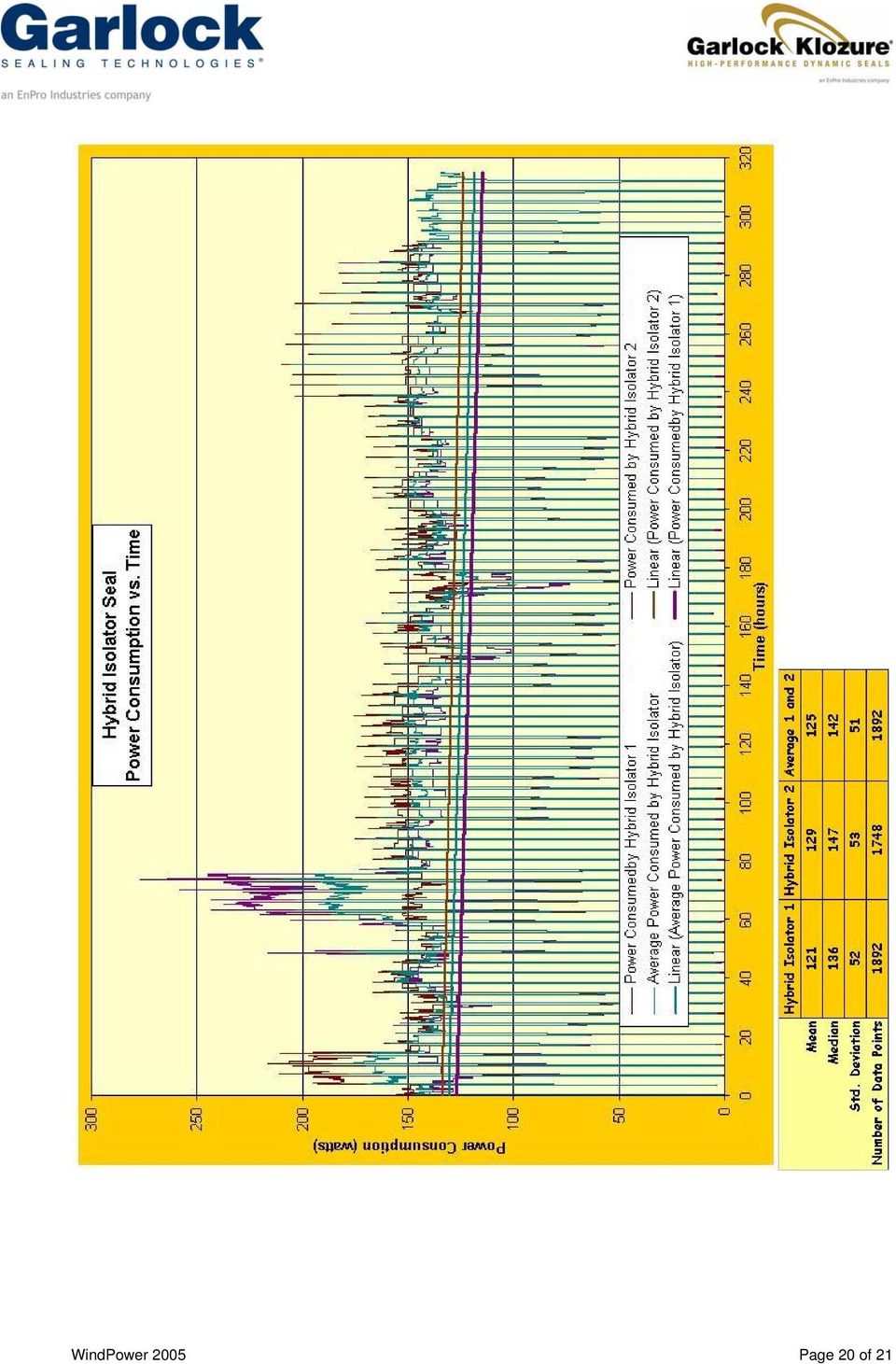
13 Procedure Each seal was run for 3 hours, and then stopped for 30 minutes. The cycle then repeated for 315 hours. The stop / start cycle simulates the extremes of extended life, with a series of shutdowns. Results The lip seal required an average of 285 watts of power. During startup, the power requirements spiked as high as 670 watts. By contrast, a standard labyrinth isolator seal required an average of 120 watts of power, with spikes up to 149 watts during startup. The hybrid isolator seal required an average 140 watts of power, with spikes up to 274 watts during startup. See Chart 1. All data can be seen in Appendix A All Seal TypesAverage* *Idle time data removed Power Consumption vs. Time Average Power Consumed by Standard Isolator Average Power Consumed by Lip Seal Average Power Consumed by Hybrid Isolator Linear (Average Power Consumed by Standard Isolator) Linear (Average Power Consumed by Lip Seal) Linear (Average Power Consumed by Hybrid Isolator) Power Consumption (watts) Time (hours) Chart 1 - Power Consumption* *Data showing no power consumption during the 30 minute off period has been removed WindPower 2005 Page 13 of 21

14 Field Experiences and Life Expectancy The following are from field records of isolator seals and rubber lip seals in rotating equipment. Case 1 Background Information Industry Equipment Temperature Media Pressure Shaft Size Surface Speed at the Shaft Run Time Steel Production Hot Strip Mill Motors Ambient Oil None, oil sump vented 3.250, and FPM to 1001 FPM* Rubber Lip Contact Seal Life: 2 to 4 weeks. Frequent seal changes required to maintain protection of bearing lubricant. *Based on 850 to 900 RPM 24 hours/day 6 days/week 52 week/year Seal Life Improved 65X Using Isolators Non-Contacting Isolator Life: 5 years and continuing. First installed April 2000 and still in service. Effectively protecting bearing lubricant, increasing time between required maintenance. Case 2 Background Information Industry Equipment Temperature Media Pressure Shaft Size Surface Speed at the Shaft Run Time Pulp & Paper Production Centrifugal pumps Ambient Bearing lubricant, water from washdown, and air-borne contaminates. None, oil sump vented Ranging diameters from 0.875" to 4.250" 825 to 1947 FPM* Rubber Lip Contact Seal Life: Weeks to months. Lip seals damaged shafts and did not effectively seal out water during wash down. Seals would wear and allow contaminants and water to compromise the lubricant and damage the bearings. *Based on 0.875" shaft at 3600 RPM and 4.25" shaft at 1750 RPM 24 hours/day 7 days/week 52 weeks/year Seal Life Improved 5X to 65X Using Isolators Non-Contacting Isolator Life: 4 to 5 years 1990's - began using hydrodynamic isolators 1998 to present - standard isolator design Seals were replaced when they were damaged during pump rebuild. In all cases isolators have been replaced for reasons not related to seal performance or wear. WindPower 2005 Page 14 of 21

15 Case 3 Rubber Lip Contact Background Information Seal Pulp & Paper Life: 3 months. Industry Production Equipment Mixer Lip seals leaked due Temperature 150 F to exposure to water Media Water and paper stock spray and paper stock. Pressure None, oil sump vented Shaft Size 6" diameter 785 FPM* Surface Speed at the Shaft *Based on 6" shaft at 500 RPM 24 hours/day Run Time 7 days/week 52 weeks/year Seal Life Improved 12X Using Isolators Non-Contacting Isolator Life: 3 years Installed Service ended when machinery was removed in Seals operated with no issue during the 3 year span. WindPower 2005 Page 15 of 21

16 Appendix A Seal Test Data WindPower 2005 Page 16 of 21

17 WindPower 2005 Page 17 of 21

18 WindPower 2005 Page 18 of 21

19 WindPower 2005 Page 19 of 21

20 WindPower 2005 Page 20 of 21
21 WindPower 2005 Page 21 of 21
Having given due consideration to all aspects
 INTRODUCTION 2 Introduction. Having given due consideration to all aspects of the shaft seal assembly (including the bore, the shaft, and the design of the seal itself), what remains is to successfully
FIXED DISPLACEMENT HYDRAULIC VANE PUMPS BQ SERIES
 BQ FIXED DISPLACEMENT HYDRAULIC VANE PUMPS BQ SERIES Versatility, power, compactness and low running costs are the main characteristics of B&C vane pumps. All the components subject to wear are contained
FIXED DISPLACEMENT HYDRAULIC VANE PUMPS BQ SERIES
 BQ FIXED DISPLACEMENT HYDRAULIC VANE PUMPS BQ SERIES Versatility, power, compactness and low running costs are the main characteristics of B&C vane pumps. All the components subject to wear are contained
FIXED DISPLACEMENT HYDRAULIC VANE PUMPS BQ SERIES
 BQ FIXED DISPLACEMENT HYDRAULIC VANE PUMPS BQ SERIES Versatility, power, compactness and low running costs are the main characteristics of B&C vane pumps. All the components subject to wear are contained
BSM MOTOR DRIVEN CENTRIFUGAL PUMPS
 PRINCIPLE OF OPERATION A hydraulically and dynamically balanced impeller with raised vane sections discharges liquid as a result of the centrifugal force developed in rotation. The head developed is entirely
Bearing Failure: Causes and Cures
 Bearing Failure: Causes and Cures bearing.ppt Page 1 Excessive loads usually cause premature fatigue. Tight fits, brinelling and improper preloading can also bring about early fatigue failure. The solution
Goulds AF. Axial Flow Pump
 Goulds AF Axial Flow Pump Goulds AF The Industry Leader in Circulating Pump Technologies Fabricated design 42-66 (1050-1600 mm) (shown with optional spring mounted base) Cast design 6-36 (150-900 mm) Goulds
Q&A Session for Advanced Ball Screws 102: Troubleshooting for Design Engineers
 Q&A Session for Advanced Ball Screws 102: Troubleshooting for Design Engineers Topic: Noise Q: Is there a way to predict/calculate noise on a ball screw? A: No, there is no way to calculate the noise of
Mechanical shaft seal types and sealing systems
 Chapter 2 Mechanical shaft seal types and sealing systems 1. Mechanical shaft seal types 2. Sealing systems 3. Selecting a mechanical shaft seal Mechanical shaft seal types and sealing systems 1. Mechanical
An SPX Process Equipment Operation. Universal II Industrial Series Rotary Positive Displacement ECP Pumps
 An SPX Process Equipment Operation Universal II Industrial Series Rotary Positive Displacement ECP Pumps New levels of performance. Reduced operational and maintenance costs. For more than half a century,
Comparison of Bearings --- For the Bearing Choosing of High-speed Spindle Design. Xiaofan Xie. Dept. of Mechanical Engineering, University of Utah
 Comparison of Bearings --- For the Bearing Choosing of High-speed Spindle Design Xiaofan Xie Dept. of Mechanical Engineering, University of Utah ABSTRACT: Bearing is the most important part of my project
due to uncertainty. This, in turn, has a direct impact on equipment availability and maintenance costs. Unfortunately, due to misconceptions and
 due to uncertainty. This, in turn, has a direct impact on equipment availability and maintenance costs. Unfortunately, due to misconceptions and pressure from plant operators to get "back on line", it
300 SERIES 331, 332, 333, 344, 356 AND 367 MODELS
 Section: MOYNO 500 PUMPS Page: 1 of 8 Date: March 1, 1998 SERVICE MANUAL MOYNO 500 PUMPS 300 SERIES 331, 332, 333, 344, 356 AND 367 MODELS Mechanical Seal Models Packing Gland Models MODELS DESIGN FEATURES
Repair of Hyd-ro-ac Actuators
 Repair of Hyd-ro-ac Actuators OVERHAUL INSTRUCTIONS SS-.2A-1V SS-.5A-1V SS-.5A-2V Read the entire contents of these instructions before installing the actuator and before making any connections to the
PS-SEAL PTFE based high performance seal
 PS-SEAL PTFE based high performance seal Advancing the Science of Sealing Advancing the Science of Sealing Table of content PS-SEAL 3 PS-SEAL STANDARD Standard seal in stock 4 PS-SEAL NON-STANDARD Customized
GEAROLOGY 4-1 WORMS AND WORM GEARS WORMS AND WORM GEARS
 GEAROLOGY 4-1 4 4-2 GEAROLOGY COMMON APPLICATIONS: Worm and worm gear sets are used in many, everyday products including: electrical mixers, hubometers, right Now that you have an understanding of two
Excerpted From Components Toughen Up
 A l t r a I n d u s t r i a l M o t i o n Warner Electric Boston Gear TB Wood s Formsprag Clutch Wichita Clutch Marland Clutch Excerpted From Components Toughen Up Industrial Clutch Bauer Gear Motor Svendborg
Pump Skid Fabrication for Magnetic Coupling. Rick Soltis Chief Mechanic City of Bedford
 Pump Skid Fabrication for Magnetic Coupling Rick Soltis Chief Mechanic City of Bedford Contents Magnetic Couplings What They Are, How They Work, Where They re Used Fabrication and Manufacturing of Pump
ALIGNMENT. Pump and Driver Alignment
 ALIGNMENT Pump and Driver Alignment Alignment Subject: Pump and Driver Alignment In the pump business alignment means that the centerline of the pump is aligned with the centerline of the driver. Although
Uniquely designed and engineered specifically for the pulp and paper industry.
 Universal SPU2 Series Uniquely designed and engineered specifically for the pulp and paper industry. For more than half a century, Waukesha Cherry-Burrell has been a leader in the design, manufacturing
Reliability. The Essentials of Eliminating Downtime of your Electric Motor. Asset Management? Or, Maintenance Management, Re-branded?
 for maintenance reliability and asset management professionals feb/march 14 Reliability The Essentials of Eliminating Downtime of your Electric Motor Asset Management? Or, Maintenance Management, Re-branded?
SJT / SJM / SJP Large Vertical Pumps
 SJT / SJM / SJP Large Vertical Pumps The Heart of Your Process SJT, SJM, SJP Large Vertical Pumps Product Overview SJT Turbine Ns 1800 < 5000 nq 35 < 110 SJM Mixed Flow Ns 5800 < 8300 nq 113 < 161 SJP
Pump Specifications 405 Series Commercial Drain Pump (High-Temp) 2 Solids handling
 2 Solids handling") Pump Specifications 405 Series Commercial Drain Pump (High-Temp) 2 Solids handling 405_P1 R1/27/2012 Copyright 2012 Liberty Pumps Inc. All rights reserved. Specifications subject to change without notice.
Pump Specifications 405 Series Commercial Drain Pump (High-Temp) 2 Solids handling 405_P1 R1/27/2012 Copyright 2012 Liberty Pumps Inc. All rights reserved. Specifications subject to change without notice.
Machine tool optimization
 Machine tool optimization SKF solutions for super-precision, productivity and sustainability The Power of Knowledge Engineering Run faster, longer, Machine tools: whether you are designing them or using
Field Application Note
 Field Application Note Reverse Dial Indicator Alignment RDIA Mis-alignment can be the most usual cause for unacceptable operation and high vibration levels. New facilities or new equipment installations
Fixed displacement vane pumps
 Fixed displacement vane pumps RE 1335/1.5 Replaces: 11.2 1/22 Types PVV and PVQ Nominal sizes 18 to 193 Series 1X Maximum operating pressure 21 bar Maximum displacement 18 to 193 cm 3 Doppelpumpe_d_ Double
Handling Corrosive or Abrasive Liquids
 Handling Corrosive or Abrasive Liquids Defining abrasion and corrosion An abrasive liquid is one that has particles in it. Some, like inks, have very fine particles, while others, like some paints, contain
DEVELOPMENT OF A TWIN SCREW EXPRESSOR AS A THROTTLE VALVE REPLACEMENT FOR WATER-COOLED CHILLERS
 DEVELOPMENT OF A TWIN SCREW EXPRESSOR AS A THROTTLE VALVE REPLACEMENT FOR WATER-COOLED CHILLERS J J Brasz, Carrier Corporation, Syracuse, NY, 13221, USA joost.j.brasz@carrier.utc.com I K Smith and N Stosic
Unit: mm(in) Item Standard value Service limit Axle shaft run out - 0.2(0.008)
 Item Standard value Service limit Axle shaft run out - 0.2(0.008)") Rear Wheel/Brake/Suspension 13. Rear Wheel/Brake/Suspension Service Information 13-1 Troubleshooting 13-2 Rear Wheel 13-3 Rear Cushion 13-4 Rear Swing Arm 13-7 Service Information General Safety If the
Rear Wheel/Brake/Suspension 13. Rear Wheel/Brake/Suspension Service Information 13-1 Troubleshooting 13-2 Rear Wheel 13-3 Rear Cushion 13-4 Rear Swing Arm 13-7 Service Information General Safety If the
Simmerring BA.../SL to DIN 3760 A/AS
 Simmerring BA.../SL to DIN 3760 A/AS Simmerring BA.../SL to DIN 3760 A/AS Simmerring BAUX2, BAUSLX2, BAFUDX7, BAFUDSLX7, BA, BASL, BAU, BAUSL Product advantages Broad range of applications in every sector
Roller bearing life. The Reaction of AISI 52100 Bearing Steel to Heat
 Roller bearing life in high temperatures A common question maintenance personnel ask bearing companies when their equipment temperature is high or rises is, What is the maximum temperature that your rolling
Radial piston pumps type R and RG
 Radial piston pumps type R and RG Operating pressure p max = 700 bar Delivery flow Q max = 91.2 lpm (at 1450 rpm) Geometric displacement V g max = 64.2 cm 3 /rev. 1. General Motor pumps and hydraulic power
Self-aligning ball bearings
 Self-aligning ball bearings Designs... 470 Basic design... 470 Sealed bearings... 470 Bearings with an extended inner ring... 472 Bearings on sleeves... 473 Self-aligning ball bearing kits... 474 Appropriate
Table of Contents. Overview 1. Pump Disassembly 2. Control Disassembly / Reassembly 7. Pump Reassembly 13. Adjustment Procedures DR Control 19
 Table of Contents Overview 1 Pump Disassembly 2 Control Disassembly / Reassembly 7 Pump Reassembly 13 Adjustment Procedures DR Control 19 Adjustment Procedures DRG Control 20 Adjustment Procedures DFR
TECHNICAL SERVICE MANUAL
 TECHNICAL SERVICE MANUAL HEAVY-DUTY PUMPS SERIES 4195 AND 495 SIZES GG - AL SECTION TSM 144 PAGE 1 of 10 ISSUE D CONTENTS Introduction....................... 1 Safety Information.................... 2
BEARINGS, TYPES & SERVICEABILITY LIMITS, FAILURE MODES
 Training Title BEARINGS, TYPES & SERVICEABILITY LIMITS, FAILURE MODES Training Duration and Dates 5 days training Bearings, Types and Serviceability Limits, Failure Modes 5 01 05 Sep $3,750 Abu Dhabi,
OPERATING AND MAINTENANCE INSTRUCTIONS PUMP TYPE 215.10
 OPERATING AND MAINTENANCE INSTRUCTIONS PUMP TYPE 215.10 To Pump model Pump number Our order Your order Order date Reference Item number Destination Plant Before storing, installation, operation or maintenance
Belt Drives and Chain Drives. Power Train. Power Train
 Belt Drives and Chain Drives Material comes for Mott, 2002 and Kurtz, 1999 Power Train A power train transmits power from an engine or motor to the load. Some of the most common power trains include: Flexible
Linear guide slides. For smooth and extremely accurate positioning
 Linear guide slides For smooth and extremely accurate positioning Complete Gilman USA slide selection Linear slides ** Built-to-order Ball or roller styles Used for high-precision, high-speed applications
Engine Bearing Materials
 Engine Bearing Materials Dr. Dmitri Kopeliovich (Research & Development Manager) The durable operation of an engine bearing is achieved if its materials combine high strength (load capacity, wear resistance,
introduction to constant level lubrication
 introduction to constant level lubrication Constant level oilers are designed to maintain a predetermined oil level in a sump, which is necessary for proper lubrication. If the oil level were to drop below
Coal Handling Plant Alignment Standards For Shaft To Shaft Alignment. By Makarand Joshi M.Tech
 Coal Handling Plant Alignment Standards For Shaft To Shaft Alignment By Makarand Joshi M.Tech 1.0 Abstract: - Shaft alignment is a technical skill that is not common in the construction and maintenance
Char-Lynn Hydraulic Motor. Repair Information. 10 000 Series. October, 1997
 Char-Lynn Hydraulic Motor October, 1997 Repair Information Geroler Motor Two Speed 001 27 Retainer inside bore of valve plate bearingless motors only 4 15 16 3 6 35 Parts Drawing 25 2 2 1 19 17 36 40 47
Typical water pump claims and causes
 Typical water pump claims and causes www.meyle.com MEYLE water pumps pioneering advancements instead of technological dead end! The water pump quality depends upon the use of high grade components. These
POSITIVE DISPLACEMENT FLOWMETER - IM012P (PULSE)
") IM213P-MC 0312 0003 POSITIVE DISPLACEMENT FLOWMETER - IM012P (PULSE) INSTRUCTION MANUAL To the Owner PLEASE READ THIS INFORMATION CAREFULLY BEFORE USE. Read and retain this instruction manual to assist
IM213P-MC 0312 0003 POSITIVE DISPLACEMENT FLOWMETER - IM012P (PULSE) INSTRUCTION MANUAL To the Owner PLEASE READ THIS INFORMATION CAREFULLY BEFORE USE. Read and retain this instruction manual to assist
Goulds 3175. Paper Stock/Process Pump with Patented Intelligent Monitoring
 Goulds 3175 Paper Stock/Process Pump with Patented Intelligent Monitoring Goulds Model 3175 Designed to Handle the Toughest Jobs in the Pulp & Paper and Process Industries Capacities to 28,000 GPM (6360
SERIES ASM NEOPRENE/EPMD FLANGED SINGLE SPHERE CONNECTOR CONNECTORS. Pressures to 225 PSIG (15.51 barg) Temperatures to 230ºF (110ºC)
 Temperatures to 230ºF (110ºC)") APPLICATIONS Process Industry Weak Acids Alkalies Compressed Air Pulp & Paper MODELS ASM - Flanged Connection OPTIONS Control Rods Oil & Gas Water & Waste Pump suction & discharge Sea water Chemical lines
APPLICATIONS Process Industry Weak Acids Alkalies Compressed Air Pulp & Paper MODELS ASM - Flanged Connection OPTIONS Control Rods Oil & Gas Water & Waste Pump suction & discharge Sea water Chemical lines
Pump Specifications 250 Series Submersible Sump / Effluent Pump 2 Solids handling
 Pump Specifications 250 Series Submersible Sump / Effluent Pump 2 Solids handling 250_P1 R10/7/2015 Copyright 2015 Liberty Pumps Inc. All rights reserved. Specifications subject to change without notice.
LINEAR MOTION CONTROL
 LINEAR MOTION CONTROL Technical Data Sheet Static Locks RLSS Series Nexen s new generation of linear holding/locking devices take rod locking technology to the next level. With superior performance, these
1.8 CRANKSHAFT OIL SEALS
 SERIES 60 SERVICE MANUAL 1.8 CRANKSHAFT OIL SEALS An oil seal is fitted between each end of the crankshaft and the bores of the flywheel housing and gear case cover to retain the lubricating oil in the
Geometry and dimensional tolerances of engine bearings
 Geometry and dimensional tolerances of engine bearings Dr. Dmitri Kopeliovich (Research & Development Manager.) 1. Hydrodynamic lubrication Engine bearings operate mostly in the hydrodynamic regime of
DESIGN, OPERATION, AND MAINTENANCE CONSIDERATIONS FOR IMPROVED DRY GAS SEAL RELIABILITY IN CENTRIFUGAL COMPRESSORS
 DESIGN, OPERATION, AND MAINTENANCE CONSIDERATIONS FOR IMPROVED DRY GAS SEAL RELIABILITY IN CENTRIFUGAL COMPRESSORS by John S. Stahley Manager, Product Service Engineering Dresser-Rand Company Olean, New
ALMATEC Series CX CX 10 CX 130
 ALMATEC Series CX CX 10 CX 130 Operating and Installation Instructions ought to be studied before installing the pump The ALMATEC Maschinenbau GmbH is certified as a modern, quality-orientated enterprise
Wafer Placement Repeatibility and Robot Speed Improvements for Bonded Wafer Pairs Used in 3D Integration
 Wafer Placement Repeatibility and Robot Speed Improvements for Bonded Wafer Pairs Used in 3D Integration Andrew C. Rudack 3D Interconnect Metrology and Standards SEMATECH Albany, NY andy.rudack@sematech.org
Pump Specifications 2448LSG, 2448LSGX Series Omnivore 2HP Simplex Grinder Packages
 Pump Specifications 2448LSG, 2448LSGX Series Omnivore 2HP Simplex Grinder Packages 2448LSG_P1 R4/2/2012 Copyright 2012 Liberty Pumps Inc. All rights reserved. Specifications subject to change without notice.
AC Electric Motors best practice
 If you want to learn more about best practice machinery maintenance, or world class mechanical equipment maintenance and installation practices, follow the link to our Online Store and see the Training
SKF composite plain bearings. Compact and maintenance-free
 SKF composite plain bearings Compact and maintenance-free Contents The SKF brand now stands for more than ever before, and means more to you as a valued customer. While SKF maintains its leadership as
BOWIE PUMPS OPERATION - MAINTENANCE
 BOWIE PUMPS OPERATION - MAINTENANCE PUMPING PRINCIPLE: The meshing owieeof the gears cause a slight depression, with the resulting enmeshing of the gears causing a vacuum drawing the fluid being pumped
VERTICAL TURBINE AND PROPELLER PUMPS
 VERTICAL TURBINE AND PROPELLER PUMPS INTRODUCTION Vertical Turbine and Propeller Pumps Model 7000 Series Turbine Pump Model 800 Series Axial Flow Propeller Pump Model 800 Series Mixed Flow Propeller Pump
Fleetguard CS41018 SpiraTec Centrifuge Rotor Installation Instructions
 Fleetguard CS41018 SpiraTec Centrifuge Rotor Installation Instructions This document describes: Product benefits How to install remote centrifuge housings How to replace the existing centrifuge rotors
POLARIS AIR COMPRESSOR SERIES. engineering. excellence. stellar. performance. A World Leader for Centrifugal Compressors
 POLARIS AIR COMPRESSOR SERIES engineering excellence stellar performance P - 3 0 0 RELIABLE 100% OIL-FREE ENGINEERED AIR A World Leader for Centrifugal Compressors It s simple: The Polaris Air Compressor
DODGE USAF 200/300 Direct Mount Pillow Block Bearings
 DODGE USAF 200/300 Direct Mount Pillow Block Bearings These instructions must be read thoroughly before installation or operation. WARNING: To ensure that drive is not unexpectedly started, turn off and
Uncompromising Customer Service. Baumann TM Sanitary and Aseptic Process Valves
 Baumann TM Sanitary and Aseptic Process Valves The Company Fisher Controls International LLC, Baumann Control Valves, is an ISO 9001 certified, PED compliant manufacturer of general utility, precision
TECHNICAL INFORMATION Bulletin
 Peerless Pump Company 2005 Dr. M.L. King Jr. Street, P.O. Box 7026, Indianapolis, IN 46207-7026, USA Telephone: (317) 925-9661 Fax: (317) 924-7338 www.peerlesspump.com www.epumpdoctor.com TECHNICAL INFORMATION
Pump Shaft Sleeves - Stratford Engineering
 Pump shafts are usually protected from erosion, corrosion, and wear at seal chambers, leakage joints, internal bearings, and in the waterways by renewable sleeves. The most common shaft sleeve function
TYPE APPROVAL CERTIFICATION SCHEME MASS PRODUCED DIESEL ENGINES
 1. Introduction TYPE APPROVAL CERTIFICATION SCHEME MASS PRODUCED DIESEL ENGINES 1.1 This scheme details the tests and inspection of diesel engines manufactured by mass production system for use in marine
Cerobear Spindle Bearings for Machine Tool Applications
 Cerobear Spindle Bearings for Machine Tool Applications Cerobear Spindle Bearings About CEROBEAR Committed to the abbreviation CEramic in ROlling BEARings, CEROBEAR GmbH is the renowned world leader in
For New Technology Network. Steel Manufacturing Machinery Product Guide Book
 For New Technology Network R Steel Manufacturing Machinery Product Guide Book Ecological / Economical proposals from NTN NTN products exhibit benefits at various locations. Steel manufacturing equipment
SKF Seals Knowledge Engineering. Designed to optimize machinery performance
 SKF Seals Knowledge Engineering Designed to optimize machinery performance From moulding high quantities to mach Sealing for power transmission The performance and service life of a power transmission
ZKL Bearings for Railway Rolling Stock
 2 ZKL Bearings for Railway Rolling Stock ZKL Bearings for Railway Rolling Stock Railway industry is a very prospective sector worldwide and therefore ZKL pays particular attention to bearings for railway
Spicer Axles & Brakes ABIB-0302
 Information Bulletin Bulletin Type: Parts / Service Information Topic: Dana LMS Hub Assembly Procedure Steer and Drive Axles Spicer Axles & Brakes ABIB-0302 Note: Bulletin ABIB-0302 replaces the original
PTFE Slide Bearings 04/10 149
 04/10 149 1.0 GENERAL INFORMATION In a wide range of applications, PTFE Slide bearings are superior to conventional expansion plates, rollers and rocker arm type supports. They support petrochemical plant,
Roller Chain Coupling
 Roller Chain Coupling Features 1. Simple structure A roller chain coupling consists of one duplex roller chain and two sprockets for a simplex chain. Handling is very simple as both the shafts (driving
Axial and Mixed Flow Pumps for Large Volume Pumping
 Vertical Industrial and Process Axial and Mixed Flow for Large Volume Pumping Encased (Can ) Water and Process Liquid Vertical Turbine for Water Supply from Drilled Wells Vertical close coupled single
APPENDIX F VIBRATION TESTING PROCEDURE
 APPENDIX F VIBRATION TESTING PROCEDURE Appendix F SPS-F-1 of 14 VIBRATION PERFORMANCE TESTING I. General Perform a vibration analysis on all motor driven equipment listed below after it is installed and
Tri-Homo Style Operation and Maintenance Instructions
 Tri-Homo Style Operation and Maintenance Instructions One Research Drive Stratford, CT 06615 (203) 375-0063 www.sonicmixing.com 1 Installation and Start-up Do not perform following adjustments without
Vertical selfpriming Side-Channel Pumps Type WPV
 Vertical selfpriming Side-Channel Pumps Type WPV FIELD OF APPLICATION The side-channel pumps are selfpriming and operate more economically (better efficiency) than normal centrifugal pumps when handling
Pumps: Convert mechanical energy (often developed from electrical source) into hydraulic energy (position, pressure and kinetic energy).
 into hydraulic energy (position, pressure and kinetic energy).") HYDRAULIC MACHINES Used to convert between hydraulic and mechanical energies. Pumps: Convert mechanical energy (often developed from electrical source) into hydraulic energy (position, pressure and kinetic
HYDRAULIC MACHINES Used to convert between hydraulic and mechanical energies. Pumps: Convert mechanical energy (often developed from electrical source) into hydraulic energy (position, pressure and kinetic
AXIAL PISTON-PRESSURE EXCHANGER DEVELOPMENT PROGRAM. 1.0 Abstract
 AXIAL PISTON-PRESSURE EXCHANGER DEVELOPMENT PROGRAM John P. MacHarg, Ocean Pacific Technologies, Ventura, CA, USA 1.0 Abstract Through a contract with the United States Office of Naval Research (ONR),
Industrial seal self study guide. Maximizing radial shaft seal performance.
 Industrial seal self study guide Maximizing radial shaft seal performance. TABLE OF CONTENTS Chapter 1 Introduction........................ 2-4 Basic Seal Types................. 5-9 Chapter 2 Review.................
World-Class Oil Sampling It is Possible
 www.lubecontrol.com.au World-Class Oil Sampling It is Possible Lube Control Pty Ltd Providing lubrication solutions! Unit 5/53 Norfolk Rd, Marion, SA 5043 t: (08) 8298 5563 f: (08) 8298 6253 e: info@lubecontrol.com.au
PRESSURE REDUCING CONTROL VALVE
 Schematics Throttles to reduce high upstream pressure to constant lower downstream pressure Low Flow By-Pass controls at low flows 4 PRESSURE REDUCING CONTROL VALVE with LOW FLOW BY-PASS FEATURE Main Line
Maintenance and Service Instruction
 Screw pumps E4 Maintenance and Service Instruction E4 1 IMO AB This instruction is valid for all E4 pump models shown on page 2 Contents Page List of components 2 Exploded view/ordering code 3 Service
M A N U A L 13-10-05
 Documentation The following information sheets illustrate the description below: 12-WW01-4G-E Sectional view of the lance with main dimensions 12-W101-6G-E Sectional view of the head of the lance with
MINEX -S. Magnetic coupling. You will find continuously updated data in our online catalogue at www.ktr.com
 MINEX - 171 Table of contents NEW MINEX - 171 Coupling description 173 Technical description 174 s A 22/4 to B 60/8 with containment shroud made of stainless steel 175 s A 75/10 to F 250/38 with containment
FLSmidth ball mill for cement grinding
 FLSmidth ball mill for cement grinding 2 Versatile system based on standard modules Main features - Shell supported ball mill of well-proven design - Side or central drive - Grinds all types of cement
Machine Design II Prof. K.Gopinath & Prof. M.M.Mayuram. Module 2 - GEARS. Lecture 17 DESIGN OF GEARBOX
 Module 2 - GEARS Lecture 17 DESIGN OF GEARBOX Contents 17.1 Commercial gearboxes 17.2 Gearbox design. 17.1 COMMERCIAL GEARBOXES Various commercial gearbox designs are depicted in Fig. 17.1 to 17.10. These
Bearing designs. Bearing testing. Extract from the Railway technical handbook, volume 1, chapter 4, page 99 to 105
 Bearing designs Bearing testing Extract from the Railway technical handbook, volume 1, chapter 4, page 99 to 105 Railway technical handbook Volume 1 xleboxes, wheelset bearings, sensors, condition monitoring,
IMPORTANT DOCUMENTATION DO NOT DISCARD!
 PART NO.: 6441-263C SERIES GRT 3 JAW PARALLEL GRIPPERS INFORMATION SHEET IMPORTANT DOCUMENTATION DO NOT DISCARD! Use this information sheet to assist with gripper installation and setup. File with maintenance
HIGH TEMPERATURE TWIN SCREW PUMPS. By: David B. Parker Two Screw Product Engineer IMO Pump Warren Warren, Massachusetts
 HIGH TEMPERATURE TWIN SCREW PUMPS By: David B. Parker Two Screw Product Engineer IMO Pump Warren Warren, Massachusetts David B. Parker is the Two Screw Product Engineer for IMO Pump - Warren, in Warren,
Configured Linear Motion Assemblies Reduce Engineering and Assembly Costs and Leadtime
 Configured Linear Motion Assemblies Reduce Engineering and Assembly Costs and Leadtime Kyle Thompson, Associate Product Line Manager Thomson Industries, Inc. www.thomsonlinear.com www.linearmotioneering.com
Increase the efficiency of your rotating machines by optimizing your bearing lubrication
 Increase the efficiency of your rotating machines by optimizing your bearing lubrication I. Introduction When designing oil lubrication systems for bearings, the classical criteria are the necessity for:
Rolling Bearing for Environments of Ultrahigh Temperatures
 [ New Product ] Rolling Bearing for Environments of Ultrahigh s Miki ARIHANA* Takayuki KAWAMURA** In recent years the demand of bearings which are used at 4 degree C for tenter clips, glassmaking facility
Chapter 7 Hydraulic System Troubleshooting
 Chapter 7 Hydraulic System Troubleshooting General The following troubleshooting information is provided as a general guide to identify, locate and correct problems that may be experienced with the hydraulic
Helical Gears K HG 1-20 R. Table of Contents. Catalog Number of KHK Stock Gears. Helical Gears. (Example) Direction of Helix (R) No.
 Direction of Helix (R) No.") Table of Contents Special Characteristics, Points of Caution in Selecting and Using... page 130 KHG Ground... page 134 SH... page 144 Catalog Number of KHK Stock Gears The Catalog Number for KHK stock
Table of Contents Special Characteristics, Points of Caution in Selecting and Using... page 130 KHG Ground... page 134 SH... page 144 Catalog Number of KHK Stock Gears The Catalog Number for KHK stock
Trouble Shooting. Pump
 Trouble Shooting Pump Trouble Possible Cause Remedy Oil leaking in the area of water pump crankshaft Worn crankshaft seal, bad bearing, grooved shaft, or failure of retainer o-ring. Excessive play on crankshaft
Rexroth Linear Motion Technology
 2 Bosch Rexroth Corp. Linear Motion and Assembly Technologies Ball Rail Systems R310A 2202 (2007.05) Rexroth Linear Motion Technology Ball Rail Systems Roller Rail Systems Linear Bushings and Shafts Standard
CDX. EBARA PUMPS EUROPE S.p.A. CENTRIFUGAL PUMPS. Page - CONTENTS 100
 CONTENTS Page - CONTENTS 100 - SPECIFICATIONS 200 SELECTION CHARTS 201 PERFORMANCE CHART 70 202 PERFORMANCE CHART 90 203 PERFORMANCE CHART 120 204 PERFORMANCE CHART 200 205 - CONSTRUCTIONS 300 SECTIONAL
TECHNICAL SPECIFICATION
 THOMAS - G-FLEX GFLEX TECH SPEC CONNECTING INNOVATION JOHANNESBURG TEL: +27 11 794 7594 CAPE TOWN TEL: +27 21 556 5258 POLOKWANE TEL: 015 298 9142 DESIGNER, MANUFACTURER AND DISTRIBUTOR OF PIPE CONNECTION,
Slide the new steering column shaft through the steering column from the driver compartment.
 Slide the new steering column shaft through the steering column from the driver compartment. Push the column shaft through the steering column until the machined end is out past the column lower bushing.