ENGR-2300 Electronic Instrumentation Quiz 1 Spring 2015
|
|
|
- Pierce Hoover
- 8 years ago
- Views:
Transcription
1 ENGR-2300 Electronic Instrumentation Quiz Spring 205 On all questions: SHOW ALL WORK. BEGIN WITH FORMULAS, THEN SUBSTITUTE ALUES AND UNITS. No credit will be given for numbers that appear without justification. Read the entire quiz before answering any questions. Also it may be easier to answer parts of questions out of order. K. A. Connor

2 The School of Engineering started with 75 students in 990/9 and currently offers associate degrees in technology, baccalaureate programs in Mechanical Engineering, Electrical Engineering, Computer Engineering, Civil Engineering (as of 203) and Industrial Management Engineering, and Masters in Administration of Telecommunications and Network Systems and in Mechanical Engineering with concentrations in Alternative Energy and Aerospace Engineering. Presently, the School has 500 students in Associate Degree Programs, 900 in Bachelor Degree Programs and 50 in Masters Programs. Workshop: Diffusion of Hands-On Learning in Puerto Rico Using the Analog Discovery Board Date: 2 February 205 The workshop was attended by about two dozen professors from essentially all Puerto Rican engineering schools. Included in the participant list were RPI graduates. The workshop was organized by Prof Juan Morales, head of Mechanical Eng at Turabo and his colleagues Mary Ruales (ME) and Idalides ergara-laurens (Computer Eng). It was led by me (KC) and Prof. Yacob Astatke from Morgan State University. It was 85 degrees but rained a little. Nice change from Troy. As is typically the case in these workshops, you all pick up how to use the equipment faster than most professors. However, they rapidly came up to speed and had lots of fun. 2 K. A. Connor

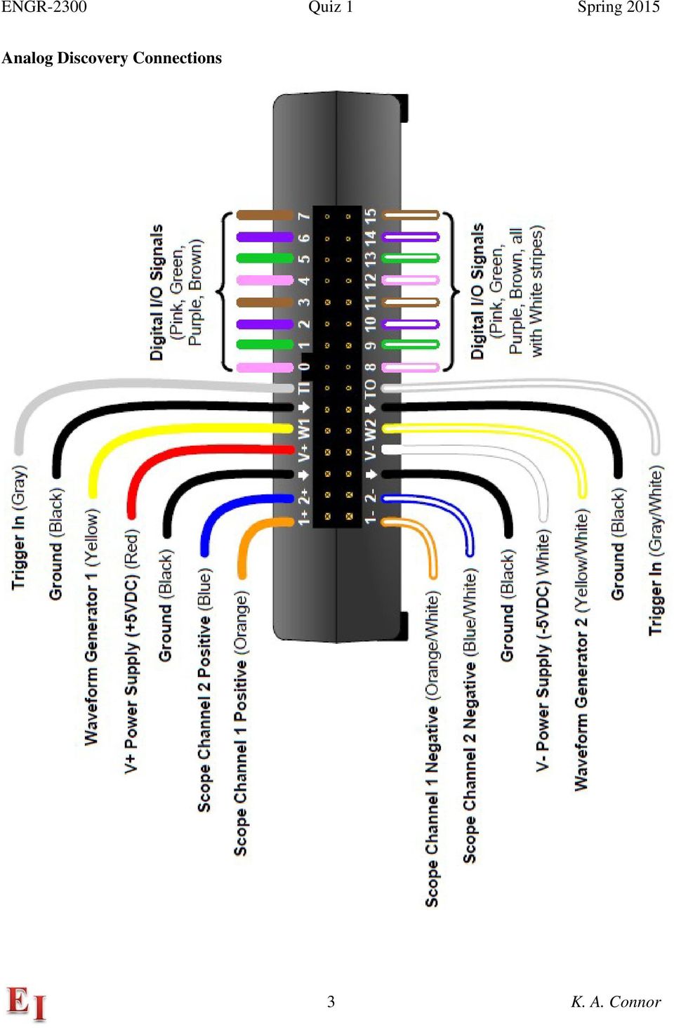
3 Analog Discovery Connections 3 K. A. Connor
4 4 K. A. Connor
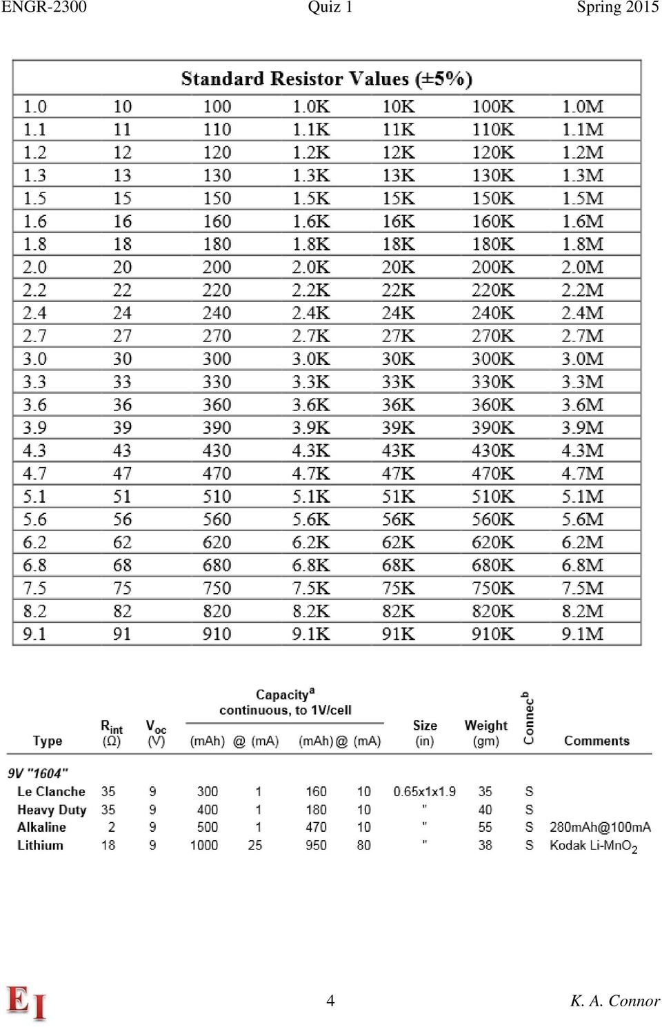
5 I. oltage Dividers (20 points) a) Find the voltage out in the circuit below. (4 pts) in 9.6dc R 6k R2 6k out Ground out in b) Find the current I in resistor R. (4 pts) 0 I 2.6 / mA c) 00W incandescent lightbulbs were banned in 202 (followed soon by 75W, 60W, and 40W bulbs) because only about 5% of the energy they use comes out as light. They are mostly heat producers. Since 20% of the energy we use goes to lighting our homes and businesses, the impact of this ban is potentially very great. Basically, a traditional lightbulb is just a resistor that gives off a little light. How large is that resistance? At 2 20, R P where P Rbat is average power. (20 is an RMS AC voltage, which is what we use to obtain average power for R3 an AC signal.) Then, R Ω. You decide to measure the resistance, but you do in 9dc out2 not have a Multimeter so Rbulb you use a voltage divider configured with a Heavy Duty 9 battery, a 0 Ground2 5 K. A. Connor

6 standard resistor and the bulb. Using the standard resistance that is closest in value to 44Ω, you measure an output voltage of 0.4. Using this information, find the value of the bulb resistance. This is called the cold resistance, because the bulb will not be turned on at these low voltages. Hint: Be sure to check the additional information provided with this quiz. (8 pts) Rbat 35 Ohms, closest R to 44 is 50 Ohms R then solve for R 8.6 Ohms (5% error OK) R d) To do the cold resistance measurement experiment, you must be sure that the standard resistor you use can handle enough power. Which of the following types of resistors will work in this experiment? Determine the power delivered to resistor R3 and then circle all possible answers. (4 pts) /4W /2W W 2W The current is 0.4/8.6 47mA 2 I R 324mW so the quarter Watt resistor will not work, but the other three will. 6 K. A. Connor
 35 + 50 + R d) To do the cold resistance measurement experiment, you must be sure that the standard resistor you use can handle enough power.")
7 II. Resistor Combinations (20 points) A R B R2 C R3 D R4 E R5 F 0k 0k 0k 0k 0k 32dc R6 20k R7 20k R8 20k R9 20k R0 0k 0 One of the important things you should learn about electronics is to never throw away a power supply from obsolete or broken equipment. For example, a power supply for HP printers outputs 32 or 6 DC. Assume you have such a supply and build the resistor ladder circuit shown above to provide a series of reference voltages. G R 0k H R2 0k I 0k+0k 20k 20k 20k 0k 32dc 2 R6 20k R7 0k H is middle of voltage divider Made with two 0k resistors oltage at I is also half H G: 32 H: 6 I: K. A. Connor

8 Before building and analyzing the full ladder, you put together the smaller one to be sure you understand how it works. a) Determine the voltages at points G, H and I in the smaller ladder. Hint: Begin by simplifying the circuit until it looks like a standard voltage divider. (4 pts) See above. The voltage at G is 32, the voltage at H is 6 and the voltage at I is 8 b) Now, determine the voltages at the points A, B, C, D, E and F in the larger divider. (0 pts) Hint: The voltage divider is also useful for this. Each divider halves the voltage because the resistors are identical. Thus, the voltage at A is 32, at B is 6, at C is 8, at D is 4, at E is 2 and at F is. c) Determine the current drawn from the power supplies for both circuits. Then use this current to determine the power for both circuits. Can this power supply produce enough power to drive either or both of these ladder circuits? Explain your answer. (6 pts) Since the voltage between A and B is 6 and between G and H is also 6, the current is 6/0mA or.6ma as confirmed by PSpice The power is 32 times.6 mw or 5.2mW. The power supply can source 375mA at 32 so no problem at all. 8 K. A. Connor
 Hint: The voltage divider is also useful for this. Each divider halves the voltage because the resistors are identical.")
9 III. Filters & Transfer Functions (20 points) A 4 2 B C 4 2 D 4 a) Shown above are the four basic, two-element, passive filter configurations made with RL and RC combinations. Determine the general complex transfer function for each circuit in terms of R, L, C and frequency ω, by modeling each as a voltage divider. (4 pts) A) RL: OUT IN 34 2 jωl R + jωl B) RC: OUT IN 34 2 jωc R + jωc + jωrc C) LR: OUT IN 34 2 R R + jωl D) CR: OUT IN 34 2 R + R jωc jωrc + jωrc Either form of the solutions is OK. 9 K. A. Connor

10 b) Assume all four circuits are made with ideal components. Identify which are high pass filters and which are low pass filters by circling the high pass and underlining the low pass in the following list (4 pts): RC CR RL LR c) Assume that one of the four circuits is enclosed in an unmarked, black box, like the one shown at the left. That is, we know that the box contains one of the circuits and decide to make a series of measurements to identify which one it is by making various connections with the inputs and outputs. We first try the identification by making the DC resistance measurements listed in the table below. Identify the circuit tested by adding its name to the table in the column labeled Circuit. Explain your answer. Hint: The R, L & C are realistic circuit components and, thus, are not necessarily represented by just their ideal circuit elements. (4 pts) R 2 R 3 R 34 R 24 Circuit R 2 SC Load.kΩ 00Ω kω 0 C or LR 00 Ohms Explanation: At DC treat the inductor as a 00Ohm resistor. Then it is a voltage divider. d) What input resistance R 2 would be measured when the load is a short circuit (SC)? Add your answer to the table. (4 pts) See table. e) A function generator (amplitude ) is connected to the input of the circuit and the output voltage is measured as a function of frequency. The frequency of the function generator is changed and the phase shift between the input and output voltage is measured, as shown in the table below. Phase Shift 0 Deg -5 Deg -30 Deg -45 Deg -60 Deg -75 Deg -90 Deg Frequency 30Hz 4.7kHz 0.3kHz 7.6kHz 30.4kHz 65.5kHz 0MHz From the information in the table, determine the value of the inductance L or capacitance C for the circuit. (4 pts) The phase shift at the corner frequency is 45 degrees. Thus the corner freq is 7.6kHz or ω is R 00 0,584. L 0mH ω 0584 c 0 K. A. Connor

11 I Signals, Transformers and Inductors (20 points) R in TX out 35 FREQ 30kHz AC 824 R2 65 L_ALUE 500mH L2_ALUE 5mH 0 Given the circuit above, assume an ideal transformer with full coupling. In your answers to the following questions, use all available and useful information. a) For the given information, write out the expressions for the ratios out/in, Iout/Iin and the transformer input impedance Rin. (6 pts) 5mH 500mH 0 N N 2 out a I out 0 and I in in I I in out or Z in 00R Ω b) Draw the circuit diagram for the voltage divider consisting of the transformer input impedance Rin and the resistance R. Then solve for in, the voltage across the input terminals of the ideal transformer. (4 pts) Because the Z in is 6.5kΩ and the other resistor is 35Ω, essentially all of the voltage appears across Z in so in is 824. K. A. Connor
 5mH 500mH 0 N N 2 out a I out 0 and I in in I I in out or Z in 00R 2 6500Ω b) Draw the circuit diagram for the voltage divider consisting of the transformer input impedance Rin and the")
12 c) Find out from your value for in. (3 pts) out is 0 times smaller so it is 82.4 d) Determine both the primary and secondary currents (I and I2). (4 pts) This can be done several ways, but the easiest is I in is 824/6500) or 280mA and I out is 0 times larger or 2.8A. e) Determine the power delivered to the load R2. (3 pts) 82.4(2.8) 50W (actually 506.4W with nothing rounded off) 5% error OK. f) What is the significance of the number 824 in the history of RPI? What is the significance of the number 35 in the history of RPI? (Up to 2 pts extra credit) RPI was founded in 824 and the 985 men s RPI hockey team had 35 wins in its national championship season. Actually, any clever answer for 35 will be accepted, but 824 must be correct. 2 K. A. Connor

13 Misc & Concepts (20 points) The following questions all come from the daily videos and were asked at the beginning of class. The answers for all questions are worth ( pt) each, except where noted. a) What are the colors & names of the two wires for Scope Ch? Orange/+ and Orange with white stripe/- b) What are the colors & names of the two wires for Scope Ch2? Blue/2+ and Blue with white stripe/2- c) What are the colors & names of the two wires for Arbitrary Waveform Generator (AWG)? This one is a little tricky. Yellow/W for one wire and Black/Ground for the other d) Is it always necessary to measure both the input and output voltage or current for every circuit studied? Yes. e) In a resistive voltage divider, will the output voltage always be less than the input? Lower because the output is taken across only one of the two resistors f) What is the input impedance of an Analog Discovery scope channel? M Ohms g) What is a typical internal resistance for a 9 heavy duty battery? Ohms h) What is the magnitude and phase of the transfer function for the LR circuit above at high (not infinite) frequencies? Trans Func R/(R+ωjL) so Mag is R/ωL, phase is -90degrees 3 K. A. Connor
 Is it always necessary to measure both the input and output voltage or current for every circuit studied? Yes.")
14 i) What is meant by a low frequency or a high frequency when dealing with RC, RL or RLC circuits? (3 pts) Be specific for each configuration. i. RC R << /(ωc) for low (other direction for high) ii. RL R >> ωl for low (other direction for high) iii. RLC for low, both low conditions above or high, other set j) In the CR circuit above, is the current in R large or small when the frequency is low? Low frequency, C is open, current is small. k) What is the purpose of an ideal model for an inductor if the analytical formula we can derive from it does not provide a particularly accurate prediction of inductance? It is used to estimate inductance values so other circuit parameters can be selected to be near what is needed. l) What could you do to improve the coupling of your transformer so that it will work equally well in both step up and step down modes? Either wind the two coils to be the same length or wind them on a magnetic core. Either answer is OK 4 K. A. Connor
 What is the purpose of an ideal model for an inductor if the analytical formula we can derive from it does not provide a particularly accurate prediction of inductance?")
15 Input Output m) In the figure above, showing input and output voltages from a Joule Thief circuit, determine the approximate frequency of the train of pulses. The horizontal scale is 20µs/div. (4 pts) 7 pulses in 200µs 35kHz (any answer from 30k to 40k is OK) n) What is the color code for a kω resistor? (2 pts) Brown-Black-Red 5 K. A. Connor
 7 pulses in 200µs 35kHz (any answer from 30k to 40k is OK) n) What is the")
EE 1202 Experiment #4 Capacitors, Inductors, and Transient Circuits
 EE 1202 Experiment #4 Capacitors, Inductors, and Transient Circuits 1. Introduction and Goal: Exploring transient behavior due to inductors and capacitors in DC circuits; gaining experience with lab instruments.
ENGR-4300 Electronic Instrumentation Quiz 4 Spring 2011 Name Section
 ENGR-4300 Electronic Instrumentation Quiz 4 Spring 2011 Name Section Question I (20 points) Question II (20 points) Question III (20 points) Question IV (20 points) Question V (20 points) Total (100 points)
Transformer circuit calculations
 Transformer circuit calculations This worksheet and all related files are licensed under the Creative Commons Attribution License, version 1.0. To view a copy of this license, visit http://creativecommons.org/licenses/by/1.0/,
Circuits with inductors and alternating currents. Chapter 20 #45, 46, 47, 49
 Circuits with inductors and alternating currents Chapter 20 #45, 46, 47, 49 RL circuits Ch. 20 (last section) Symbol for inductor looks like a spring. An inductor is a circuit element that has a large
RLC Series Resonance
 RLC Series Resonance 11EM Object: The purpose of this laboratory activity is to study resonance in a resistor-inductor-capacitor (RLC) circuit by examining the current through the circuit as a function
ε: Voltage output of Signal Generator (also called the Source voltage or Applied
 Experiment #10: LR & RC Circuits Frequency Response EQUIPMENT NEEDED Science Workshop Interface Power Amplifier (2) Voltage Sensor graph paper (optional) (3) Patch Cords Decade resistor, capacitor, and
Chapter 11. Inductors ISU EE. C.Y. Lee
 Chapter 11 Inductors Objectives Describe the basic structure and characteristics of an inductor Discuss various types of inductors Analyze series inductors Analyze parallel inductors Analyze inductive
Properties of electrical signals
 DC Voltage Component (Average voltage) Properties of electrical signals v(t) = V DC + v ac (t) V DC is the voltage value displayed on a DC voltmeter Triangular waveform DC component Half-wave rectifier
45. The peak value of an alternating current in a 1500-W device is 5.4 A. What is the rms voltage across?
 PHYS Practice Problems hapters 8- hapter 8. 45. The peak value of an alternating current in a 5-W device is 5.4 A. What is the rms voltage across? The power and current can be used to find the peak voltage,
AP Physics Electricity and Magnetism #4 Electrical Circuits, Kirchoff s Rules
 Name Period AP Physics Electricity and Magnetism #4 Electrical Circuits, Kirchoff s Rules Dr. Campbell 1. Four 240 Ω light bulbs are connected in series. What is the total resistance of the circuit? What
EDEXCEL NATIONAL CERTIFICATE/DIPLOMA UNIT 5 - ELECTRICAL AND ELECTRONIC PRINCIPLES NQF LEVEL 3 OUTCOME 4 - ALTERNATING CURRENT
 EDEXCEL NATIONAL CERTIFICATE/DIPLOMA UNIT 5 - ELECTRICAL AND ELECTRONIC PRINCIPLES NQF LEVEL 3 OUTCOME 4 - ALTERNATING CURRENT 4 Understand single-phase alternating current (ac) theory Single phase AC
Power Supplies. 1.0 Power Supply Basics. www.learnabout-electronics.org. Module
 Module 1 www.learnabout-electronics.org Power Supplies 1.0 Power Supply Basics What you ll learn in Module 1 Section 1.0 Power Supply Basics. Basic functions of a power supply. Safety aspects of working
Apprentice Telecommunications Technician Test (CTT) Study Guide
 Study Guide") Apprentice Telecommunications Technician Test (CTT) Study Guide 1 05/2014 Study Guide for Pacific Gas & Electric Company Apprentice Telecommunications Technician Qualifying Test (CTT) About the Test The
Apprentice Telecommunications Technician Test (CTT) Study Guide 1 05/2014 Study Guide for Pacific Gas & Electric Company Apprentice Telecommunications Technician Qualifying Test (CTT) About the Test The
Series and Parallel Circuits
 Series and Parallel Circuits Components in a circuit can be connected in series or parallel. A series arrangement of components is where they are inline with each other, i.e. connected end-to-end. A parallel
Measuring Impedance and Frequency Response of Guitar Pickups
 Measuring Impedance and Frequency Response of Guitar Pickups Peter D. Hiscocks Syscomp Electronic Design Limited phiscock@ee.ryerson.ca www.syscompdesign.com April 30, 2011 Introduction The CircuitGear
Application Note. So You Need to Measure Some Inductors?
 So You Need to Measure Some nductors? Take a look at the 1910 nductance Analyzer. Although specifically designed for production testing of inductors and coils, in addition to measuring inductance (L),
Inductors in AC Circuits
 Inductors in AC Circuits Name Section Resistors, inductors, and capacitors all have the effect of modifying the size of the current in an AC circuit and the time at which the current reaches its maximum
Frequency response: Resonance, Bandwidth, Q factor
 Frequency response: esonance, Bandwidth, Q factor esonance. Let s continue the exploration of the frequency response of circuits by investigating the series circuit shown on Figure. C + V - Figure The
Electrical Resonance
 Electrical Resonance (R-L-C series circuit) APPARATUS 1. R-L-C Circuit board 2. Signal generator 3. Oscilloscope Tektronix TDS1002 with two sets of leads (see Introduction to the Oscilloscope ) INTRODUCTION
RLC Resonant Circuits
 C esonant Circuits Andrew McHutchon April 20, 203 Capacitors and Inductors There is a lot of inconsistency when it comes to dealing with reactances of complex components. The format followed in this document
CIRCUITS LABORATORY EXPERIMENT 3. AC Circuit Analysis
 CIRCUITS LABORATORY EXPERIMENT 3 AC Circuit Analysis 3.1 Introduction The steady-state behavior of circuits energized by sinusoidal sources is an important area of study for several reasons. First, the
Tutorial 12 Solutions
 PHYS000 Tutorial 2 solutions Tutorial 2 Solutions. Two resistors, of 00 Ω and 200 Ω, are connected in series to a 6.0 V DC power supply. (a) Draw a circuit diagram. 6 V 00 Ω 200 Ω (b) What is the total
Lab #9: AC Steady State Analysis
 Theory & Introduction Lab #9: AC Steady State Analysis Goals for Lab #9 The main goal for lab 9 is to make the students familar with AC steady state analysis, db scale and the NI ELVIS frequency analyzer.
Diode Applications. by Kenneth A. Kuhn Sept. 1, 2008. This note illustrates some common applications of diodes.
 by Kenneth A. Kuhn Sept. 1, 2008 This note illustrates some common applications of diodes. Power supply applications A common application for diodes is converting AC to DC. Although half-wave rectification
Eðlisfræði 2, vor 2007
 [ Assignment View ] [ Print ] Eðlisfræði 2, vor 2007 30. Inductance Assignment is due at 2:00am on Wednesday, March 14, 2007 Credit for problems submitted late will decrease to 0% after the deadline has
PHYSICS 360 - LAB #2 Passive Low-pass and High-pass Filter Circuits and Integrator and Differentiator Circuits
 PHYSICS 360 - LAB #2 Passie Low-pass and High-pass Filter Circuits and Integrator and Differentiator Circuits Objectie: Study the behaior of low-pass and high-pass filters. Study the differentiator and
SERIES-PARALLEL DC CIRCUITS
 Name: Date: Course and Section: Instructor: EXPERIMENT 1 SERIES-PARALLEL DC CIRCUITS OBJECTIVES 1. Test the theoretical analysis of series-parallel networks through direct measurements. 2. Improve skills
Unit/Standard Number. High School Graduation Years 2010, 2011 and 2012
 1 Secondary Task List 100 SAFETY 101 Demonstrate an understanding of State and School safety regulations. 102 Practice safety techniques for electronics work. 103 Demonstrate an understanding of proper
Experiment #11: LRC Circuit (Power Amplifier, Voltage Sensor)
") Experiment #11: LRC Circuit (Power Amplifier, Voltage Sensor) Concept: circuits Time: 30 m SW Interface: 750 Windows file: RLC.SWS EQUIPMENT NEEDED Science Workshop Interface Power Amplifier (2) Voltage
Experiment #11: LRC Circuit (Power Amplifier, Voltage Sensor) Concept: circuits Time: 30 m SW Interface: 750 Windows file: RLC.SWS EQUIPMENT NEEDED Science Workshop Interface Power Amplifier (2) Voltage
Annex: VISIR Remote Laboratory
 Open Learning Approach with Remote Experiments 518987-LLP-1-2011-1-ES-KA3-KA3MP Multilateral Projects UNIVERSITY OF DEUSTO Annex: VISIR Remote Laboratory OLAREX project report Olga Dziabenko, Unai Hernandez
LM 358 Op Amp. If you have small signals and need a more useful reading we could amplify it using the op amp, this is commonly used in sensors.
 LM 358 Op Amp S k i l l L e v e l : I n t e r m e d i a t e OVERVIEW The LM 358 is a duel single supply operational amplifier. As it is a single supply it eliminates the need for a duel power supply, thus
Step Response of RC Circuits
 Step Response of RC Circuits 1. OBJECTIVES...2 2. REFERENCE...2 3. CIRCUITS...2 4. COMPONENTS AND SPECIFICATIONS...3 QUANTITY...3 DESCRIPTION...3 COMMENTS...3 5. DISCUSSION...3 5.1 SOURCE RESISTANCE...3
RC Circuits and The Oscilloscope Physics Lab X
 Objective RC Circuits and The Oscilloscope Physics Lab X In this series of experiments, the time constant of an RC circuit will be measured experimentally and compared with the theoretical expression for
First Year (Electrical & Electronics Engineering)
") Z PRACTICAL WORK BOOK For The Course EE-113 Basic Electrical Engineering For First Year (Electrical & Electronics Engineering) Name of Student: Class: Batch : Discipline: Class Roll No.: Examination Seat
Z PRACTICAL WORK BOOK For The Course EE-113 Basic Electrical Engineering For First Year (Electrical & Electronics Engineering) Name of Student: Class: Batch : Discipline: Class Roll No.: Examination Seat
0.9V Boost Driver PR4403 for White LEDs in Solar Lamps
 0.9 Boost Driver for White LEDs in Solar Lamps The is a single cell step-up converter for white LEDs operating from a single rechargeable cell of 1.2 supply voltage down to less than 0.9. An adjustable
Fundamentals of Signature Analysis
 Fundamentals of Signature Analysis An In-depth Overview of Power-off Testing Using Analog Signature Analysis www.huntron.com 1 www.huntron.com 2 Table of Contents SECTION 1. INTRODUCTION... 7 PURPOSE...
Building the HVPS High Voltage Power Supply
 Introduction Building the HVPS High Voltage Power Supply Voltages higher than the LVPS provides kilovolts are needed in later experiments to get strong electric fields and to generate microwaves. The high-voltage
Lab 3 - DC Circuits and Ohm s Law
 Lab 3 DC Circuits and Ohm s Law L3-1 Name Date Partners Lab 3 - DC Circuits and Ohm s Law OBJECTIES To learn to apply the concept of potential difference (voltage) to explain the action of a battery in
EET272 Worksheet Week 9
 EET272 Worksheet Week 9 answer questions 1-5 in preparation for discussion for the quiz on Monday. Finish the rest of the questions for discussion in class on Wednesday. Question 1 Questions AC s are becoming
W03 Analysis of DC Circuits. Yrd. Doç. Dr. Aytaç Gören
 W03 Analysis of DC Circuits Yrd. Doç. Dr. Aytaç Gören ELK 2018 - Contents W01 Basic Concepts in Electronics W02 AC to DC Conversion W03 Analysis of DC Circuits (self and condenser) W04 Transistors and
The full wave rectifier consists of two diodes and a resister as shown in Figure
 The Full-Wave Rectifier The full wave rectifier consists of two diodes and a resister as shown in Figure The transformer has a centre-tapped secondary winding. This secondary winding has a lead attached
2. A conductor of length 2m moves at 4m/s at 30 to a uniform magnetic field of 0.1T. Which one of the following gives the e.m.f. generated?
 Extra Questions - 2 1. A straight length of wire moves through a uniform magnetic field. The e.m.f. produced across the ends of the wire will be maximum if it moves: a) along the lines of magnetic flux
SIMULATIONS OF PARALLEL RESONANT CIRCUIT POWER ELECTRONICS COLORADO STATE UNIVERSITY
 SIMULATIONS OF PARALLEL RESONANT CIRCUIT POWER ELECTRONICS COLORADO STATE UNIVERSITY Page 1 of 25 PURPOSE: The purpose of this lab is to simulate the LCC circuit using MATLAB and ORCAD Capture CIS to better
Constructing a precision SWR meter and antenna analyzer. Mike Brink HNF, Design Technologist.
 Constructing a precision SWR meter and antenna analyzer. Mike Brink HNF, Design Technologist. Abstract. I have been asked to put together a detailed article on a SWR meter. In this article I will deal
Solution Derivations for Capa #11
 Solution Derivations for Capa #11 Caution: The symbol E is used interchangeably for energy and EMF. 1) DATA: V b = 5.0 V, = 155 Ω, L = 8.400 10 2 H. In the diagram above, what is the voltage across the
Chapter 29 Alternating-Current Circuits
 hapter 9 Alternating-urrent ircuits onceptual Problems A coil in an ac generator rotates at 6 Hz. How much time elapses between successive emf values of the coil? Determine the oncept Successive s are
Analog signals are those which are naturally occurring. Any analog signal can be converted to a digital signal.
 3.3 Analog to Digital Conversion (ADC) Analog signals are those which are naturally occurring. Any analog signal can be converted to a digital signal. 1 3.3 Analog to Digital Conversion (ADC) WCB/McGraw-Hill
Resistors in Series and Parallel
 Resistors in Series and Parallel Bởi: OpenStaxCollege Most circuits have more than one component, called a resistor that limits the flow of charge in the circuit. A measure of this limit on charge flow
AC CIRCUITS - CAPACITORS AND INDUCTORS
 EXPRIMENT#8 AC CIRCUITS - CAPACITORS AND INDUCTORS NOTE: Two weeks are allocated for this experiment. Before performing this experiment, review the Proper Oscilloscope Use section of Experiment #7. Objective
Telecommunication Line Protectors
 TN CR 0025 Telecommunication Line s 1.1 The nature of telecom surges The telecom services considered in this report are transported on twisted pair. Each service has two wires, or lines, sometimes called
Resistors in Series and Parallel Circuits
 69 Resistors in Series and Parallel Circuits E&M: Series and parallel circuits Equipment List DataStudio file: Not Required Qty s Part Numbers 1 C/DC Electronics Lab EM-8656 2 D cell 1.5 volt Introduction
Reading: HH Sections 4.11 4.13, 4.19 4.20 (pgs. 189-212, 222 224)
") 6 OP AMPS II 6 Op Amps II In the previous lab, you explored several applications of op amps. In this exercise, you will look at some of their limitations. You will also examine the op amp integrator and
6 OP AMPS II 6 Op Amps II In the previous lab, you explored several applications of op amps. In this exercise, you will look at some of their limitations. You will also examine the op amp integrator and
Current Loop Tuning Procedure. Servo Drive Current Loop Tuning Procedure (intended for Analog input PWM output servo drives) General Procedure AN-015
 General Procedure AN-015") Servo Drive Current Loop Tuning Procedure (intended for Analog input PWM output servo drives) The standard tuning values used in ADVANCED Motion Controls drives are conservative and work well in over 90%
Servo Drive Current Loop Tuning Procedure (intended for Analog input PWM output servo drives) The standard tuning values used in ADVANCED Motion Controls drives are conservative and work well in over 90%
UNDERSTANDING AND CONTROLLING COMMON-MODE EMISSIONS IN HIGH-POWER ELECTRONICS
 Page 1 UNDERSTANDING AND CONTROLLING COMMON-MODE EMISSIONS IN HIGH-POWER ELECTRONICS By Henry Ott Consultants Livingston, NJ 07039 (973) 992-1793 www.hottconsultants.com hott@ieee.org Page 2 THE BASIC
Chapter 10. RC Circuits ISU EE. C.Y. Lee
 Chapter 10 RC Circuits Objectives Describe the relationship between current and voltage in an RC circuit Determine impedance and phase angle in a series RC circuit Analyze a series RC circuit Determine
DC Circuits (Combination of resistances)
") Name: Partner: Partner: Partner: DC Circuits (Combination of resistances) EQUIPMENT NEEDED: Circuits Experiment Board One Dcell Battery Wire leads Multimeter 100, 330, 1k resistors Purpose The purpose
Name: Partner: Partner: Partner: DC Circuits (Combination of resistances) EQUIPMENT NEEDED: Circuits Experiment Board One Dcell Battery Wire leads Multimeter 100, 330, 1k resistors Purpose The purpose
Diodes have an arrow showing the direction of the flow.
 The Big Idea Modern circuitry depends on much more than just resistors and capacitors. The circuits in your computer, cell phone, Ipod depend on circuit elements called diodes, inductors, transistors,
People s Physics Book
 The Big Ideas: The name electric current is given to the phenomenon that occurs when an electric field moves down a wire at close to the speed of light. Voltage is the electrical energy density (energy
Impedance Matching and Matching Networks. Valentin Todorow, December, 2009
 Impedance Matching and Matching Networks Valentin Todorow, December, 2009 RF for Plasma Processing - Definition of RF What is RF? The IEEE Standard Dictionary of Electrical and Electronics Terms defines
ECEN 1400, Introduction to Analog and Digital Electronics
 ECEN 1400, Introduction to Analog and Digital Electronics Lab 4: Power supply 1 INTRODUCTION This lab will span two lab periods. In this lab, you will create the power supply that transforms the AC wall
Lecture 24. Inductance and Switching Power Supplies (how your solar charger voltage converter works)
") Lecture 24 Inductance and Switching Power Supplies (how your solar charger voltage converter works) Copyright 2014 by Mark Horowitz 1 Roadmap: How Does This Work? 2 Processor Board 3 More Detailed Roadmap
Lecture 24 Inductance and Switching Power Supplies (how your solar charger voltage converter works) Copyright 2014 by Mark Horowitz 1 Roadmap: How Does This Work? 2 Processor Board 3 More Detailed Roadmap
12. Transformers, Impedance Matching and Maximum Power Transfer
 1 1. Transformers, Impedance Matching and Maximum Power Transfer Introduction The transformer is a device that takes AC at one voltage and transforms it into another voltage either higher or lower than
Kit 106. 50 Watt Audio Amplifier
 Kit 106 50 Watt Audio Amplifier T his kit is based on an amazing IC amplifier module from ST Electronics, the TDA7294 It is intended for use as a high quality audio class AB amplifier in hi-fi applications
Power supplies. EE328 Power Electronics Assoc. Prof. Dr. Mutlu BOZTEPE Ege University, Dept. of E&E
 Power supplies EE328 Power Electronics Assoc. Prof. Dr. Mutlu BOZTEPE Ege University, Dept. of E&E EE328 POWER ELECTRONICS Outline of lecture Introduction to power supplies Modelling a power transformer
ES250: Electrical Science. HW7: Energy Storage Elements
 ES250: Electrical Science HW7: Energy Storage Elements Introduction This chapter introduces two more circuit elements, the capacitor and the inductor whose elements laws involve integration or differentiation;
PHYSICS 111 LABORATORY Experiment #3 Current, Voltage and Resistance in Series and Parallel Circuits
 PHYSCS 111 LABORATORY Experiment #3 Current, Voltage and Resistance in Series and Parallel Circuits This experiment is designed to investigate the relationship between current and potential in simple series
Iron Powder Cores for Switchmode Power Supply Inductors. by: Jim Cox
 HOME APPLICATION NOTES Iron Powder Cores for Switchmode Power Supply Inductors by: Jim Cox Purpose: The purpose of this application note is to cover the properties of iron powder as a magnetic core material
BSNL TTA Question Paper-Instruments and Measurement Specialization 2007
 BSNL TTA Question Paper-Instruments and Measurement Specialization 2007 (1) Instrument is a device for determining (a) the magnitude of a quantity (b) the physics of a variable (c) either of the above
Pulsed Power Engineering Diagnostics
 Pulsed Power Engineering Diagnostics January 12-16, 2009 Craig Burkhart, PhD Power Conversion Department SLAC National Accelerator Laboratory Diagnostic Techniques and Considerations in Pulsed Power Systems
Series and Parallel Resistive Circuits Physics Lab VIII
 Series and Parallel Resistive Circuits Physics Lab VIII Objective In the set of experiments, the theoretical expressions used to calculate the total resistance in a combination of resistors will be tested
Common-Emitter Amplifier
 Common-Emitter Amplifier A. Before We Start As the title of this lab says, this lab is about designing a Common-Emitter Amplifier, and this in this stage of the lab course is premature, in my opinion,
Homework #11 203-1-1721 Physics 2 for Students of Mechanical Engineering
 Homework #11 203-1-1721 Physics 2 for Students of Mechanical Engineering 2. A circular coil has a 10.3 cm radius and consists of 34 closely wound turns of wire. An externally produced magnetic field of
RC NETWORKS SALES GUIDE
 SALES GUIDE INTRODUCTION TO Recent developments in electronic equipment have shown the following trends: Increasing demands for numerical control machines, robotics and technically advanced appliances
Frequency Response of Filters
 School of Engineering Department of Electrical and Computer Engineering 332:224 Principles of Electrical Engineering II Laboratory Experiment 2 Frequency Response of Filters 1 Introduction Objectives To
Basic Electrical Technology Dr. L. Umanand Department of Electrical Engineering Indian Institute of Science, Bangalore. Lecture - 33 3 phase System 4
 Basic Electrical Technology Dr. L. Umanand Department of Electrical Engineering Indian Institute of Science, Bangalore Lecture - 33 3 phase System 4 Hello everybody. So, in the last class we have been
Oscillators. 2.0 RF Sine Wave Oscillators. www.learnabout-electronics.org. Module. RF Oscillators
 Module 2 www.learnabout-electronics.org Oscillators 2.0 RF Sine Wave Oscillators What you ll Learn in Module 2 Section 2.0 High Frequency Sine Wave Oscillators. Frequency Control in RF Oscillators. LC
Resistors in Series and Parallel
 OpenStax-CNX module: m42356 1 Resistors in Series and Parallel OpenStax College This work is produced by OpenStax-CNX and licensed under the Creative Commons Attribution License 3.0 Abstract Draw a circuit
Chapter 4: Passive Analog Signal Processing
 hapter 4: Passive Analog Signal Processing In this chapter we introduce filters and signal transmission theory. Filters are essential components of most analog circuits and are used to remove unwanted
Preamble. Kirchoff Voltage Law (KVL) Series Resistors. In this section of my lectures we will be. resistor arrangements; series and
 Series Resistors. In this section of my lectures we will be. resistor arrangements; series and") Preamble Series and Parallel Circuits Physics, 8th Edition Custom Edition Cutnell & Johnson Chapter 0.6-0.8, 0.0 Pages 60-68, 69-6 n this section of my lectures we will be developing the two common types
Preamble Series and Parallel Circuits Physics, 8th Edition Custom Edition Cutnell & Johnson Chapter 0.6-0.8, 0.0 Pages 60-68, 69-6 n this section of my lectures we will be developing the two common types
CONCEPT-II. Overview of demo examples
 CONCEPT-II CONCEPT-II is a frequency domain method of moment (MoM) code, under development at the Institute of Electromagnetic Theory at the Technische Universität Hamburg-Harburg (www.tet.tuhh.de). Overview
VOLTAGE REGULATOR AND PARALLEL OPERATION
 VOLTAGE REGULATOR AND PARALLEL OPERATION Generator sets are operated in parallel to improve fuel economy and reliability of the power supply. Economy is improved with multiple paralleled generators by
Laboratory #5: RF Filter Design
 EEE 194 RF Laboratory Exercise 5 1 Laboratory #5: RF Filter Design I. OBJECTIVES A. Design a third order low-pass Chebyshev filter with a cutoff frequency of 330 MHz and 3 db ripple with equal terminations
Study Guide for the Electronics Technician Pre-Employment Examination
 Bay Area Rapid Transit District Study Guide for the Electronics Technician Pre-Employment Examination INTRODUCTION The Bay Area Rapid Transit (BART) District makes extensive use of electronics technology
Creating a Usable Power Supply from a Solar Panel
 Creating a Usable Power Supply from a Solar Panel An exploration in DC- DC converters By Kathleen Ellis Advised by Dr. Derin Sherman Department of Physics, Cornell College November 21, 2012 Introduction
Sophomore Physics Laboratory (PH005/105)
") CALIFORNIA INSTITUTE OF TECHNOLOGY PHYSICS MATHEMATICS AND ASTRONOMY DIVISION Sophomore Physics Laboratory (PH5/15) Analog Electronics Active Filters Copyright c Virgínio de Oliveira Sannibale, 23 (Revision
CALIFORNIA INSTITUTE OF TECHNOLOGY PHYSICS MATHEMATICS AND ASTRONOMY DIVISION Sophomore Physics Laboratory (PH5/15) Analog Electronics Active Filters Copyright c Virgínio de Oliveira Sannibale, 23 (Revision
LABORATORY 2 THE DIFFERENTIAL AMPLIFIER
 LABORATORY 2 THE DIFFERENTIAL AMPLIFIER OBJECTIVES 1. To understand how to amplify weak (small) signals in the presence of noise. 1. To understand how a differential amplifier rejects noise and common
Three phase circuits
 Three phase circuits THREE PHASE CIRCUITS THREE-PHASE ADVANTAGES 1. The horsepower rating of three-phase motors and the kva rating of three-phase transformers are 150% greater than single-phase motors
Chapter 22 Further Electronics
 hapter 22 Further Electronics washing machine has a delay on the door opening after a cycle of washing. Part of this circuit is shown below. s the cycle ends, switch S closes. t this stage the capacitor
Module 11: Conducted Emissions
 Module 11: Conducted Emissions 11.1 Overview The term conducted emissions refers to the mechanism that enables electromagnetic energy to be created in an electronic device and coupled to its AC power cord.
BASIC ELECTRONICS AC CIRCUIT ANALYSIS. December 2011
 AM 5-202 BASIC ELECTRONICS AC CIRCUIT ANALYSIS December 2011 DISTRIBUTION RESTRICTION: Approved for Pubic Release. Distribution is unlimited. DEPARTMENT OF THE ARMY MILITARY AUXILIARY RADIO SYSTEM FORT
Lab 3 Rectifier Circuits
 ECET 242 Electronic Circuits Lab 3 Rectifier Circuits Page 1 of 5 Name: Objective: Students successfully completing this lab exercise will accomplish the following objectives: 1. Learn how to construct
Technical Note #3. Error Amplifier Design and Applications. Introduction
 Technical Note #3 Error Amplifier Design and Applications Introduction All regulating power supplies require some sort of closed-loop control to force the output to match the desired value. Both digital
Micro Power Generators. Sung Park Kelvin Yuk ECS 203
 Micro Power Generators Sung Park Kelvin Yuk ECS 203 Overview Why Micro Power Generators are becoming important Types of Micro Power Generators Power Generators Reviewed Ambient Vibrational energy Radiant
css Custom Silicon Solutions, Inc.
 css Custom Silicon Solutions, Inc. CSS555(C) CSS555/ PART DESCRIPTION The CSS555 is a micro-power version of the popular 555 Timer IC. It is pin-for-pin compatible with the standard 555 timer and features
8 Speed control of Induction Machines
 8 Speed control of Induction Machines We have seen the speed torque characteristic of the machine. In the stable region of operation in the motoring mode, the curve is rather steep and goes from zero torque
Oscilloscope, Function Generator, and Voltage Division
 1. Introduction Oscilloscope, Function Generator, and Voltage Division In this lab the student will learn to use the oscilloscope and function generator. The student will also verify the concept of voltage
Understanding Power Factor and How it Affects Your Electric Bill. Presented by Scott Peele PE
 Understanding Power Factor and How it Affects Your Electric Bill Presented by Scott Peele PE Understanding Power Factor Definitions kva, kvar, kw, Apparent Power vs. True Power Calculations Measurements
Experiment: Series and Parallel Circuits
 Phy203: General Physics Lab page 1 of 6 Experiment: Series and Parallel Circuits OBJECTVES MATERALS To study current flow and voltages in series and parallel circuits. To use Ohm s law to calculate equivalent
Transistor Amplifiers
 Physics 3330 Experiment #7 Fall 1999 Transistor Amplifiers Purpose The aim of this experiment is to develop a bipolar transistor amplifier with a voltage gain of minus 25. The amplifier must accept input