Recommended Design Criteria Manual. Wastewater Collection and Treatment Facilities. South Dakota Department of Environment and Natural Resources
|
|
|
- Chloe Wade
- 8 years ago
- Views:
Transcription
1 Recommended Design Criteria Manual Wastewater Collection and Treatment Facilities South Dakota Department of Environment and Natural Resources Prepared By: Staff Engineer Reviewed By: Facilities Management Engineers Division of Environmental Services Joe Foss Building Pierre, South Dakota Phone: (605) March 1991
 773-3351 March")
2 NOTICE Any mention of trade names or commercial products in this publication is for illustration purposes and does not constitute endorsement or recommendation for use by the South Dakota Department of Environment and Natural Resources. This publication is intended to establish uniformity of practice and to serve as a guide in the design and preparation of plans and specifications for compliance with the minimum requirements of the reviewing authority. The design review of the reviewing authority is primarily to determine compliance with the minimum sanitary engineering requirements and does not cover items, such as, quality of material, structural soundness, electrical and mechanical design features. The Department expressly disclaims any liability in regard to the construction or operation of a planned facility. Approval of the plans and specifications does not in any way release the applicant from the responsibility that the facility will meet all applicable State and Federal Standards when the facility is operational. i

3 FOREWORD In recognition of the needs for continued protection of public health and the waters of the State, the South Dakota Department of Environment and Natural Resources is revising and expanding the Recommended Design Criteria for Wastewater Collection Systems and Wastewater Treatment Facilities. These criteria are prepared and intended to assist engineers to establish uniformity of practice in preparing plans and specifications by providing technical information and suggesting limiting values for items upon which an evaluation of such plans and specifications will be made by the reviewing authority. Where the term "shall" or "must" is used, it is intended to mean a mandatory requirement insofar as any confirmatory action by the reviewing authority is concerned. Other terms such as "recommended, should, preferred," and the like indicate discretionary use on the part of the reviewing authority and deviations are reviewed on a "case-by- case" basis. These criteria are subject to future modifications and revisions based upon operational experience and technological development. Any questions or suggestions concerning these criteria should be directed to the Division of Environmental Regulation, Department of Environment and Natural Resources, Joe Foss Building, Pierre, South Dakota ii

4 SOUTH DAKOTA DEPARTMENT OF ENVIRONMENT AND NATURAL RESOURCES DIVISION OF ENVIRONMENTAL SERVICES Recommended Design Criteria Manual INDEX CHAPTER TITLE AND TABLE OF CONTENTS CHAPTER I: General Considerations I-1 CHAPTER II: Recommended Design Criteria For Sewers II-1 CHAPTER III: CHAPTER IV: Recommended Design Criteria For Sewage Pumping Stations, Force Mains And Pressure Sewers Recommended Design Criteria For Wastewater Stabilization And Pollution Control Ponds III-1 IV-1 CHAPTER V: Recommended Design Criteria For Aerated Ponds V-1 CHAPTER VI: Recommended Design Criteria For Preliminary Treatment Processes VI-1 CHAPTER VII: Recommended Design Criteria For Flow Equalization VII-1 CHAPTER VIII: Recommended Design Criteria For Sedimentation VIII-1 CHAPTER IX: Recommended Design Criteria For Trickling Filters IX-1 CHAPTER X: Recommended Design Criteria For Rotating Biological Contactors X-1 CHAPTER XI: CHAPTER XII: Recommended Design Criteria For Oxidation Ditches And/Or Systems Recommended Design Criteria For Disposal Of Effluent By Irrigation XI-1 XII-1 CHAPTER XIII: Recommended Design Criteria For Ground Water Monitoring Wells (WWTF) CHAPTER XIV: Land Application and Treatment of Wastewater Sludge (References) XIII-1 XIV-1 CHAPTER XV: Recommended Design Criteria For Disinfection XV-1 CHAPTER XVI: Recommended Design Criteria For Artificial Wetland Systems CHAPTER XVII: Recommended Design Criteria For Ground Water Monitoring Wells (AWMS) XVI-1 XVII-1 iii

5 CHAPTER I: General Considerations A. General Statement B. Administrative C. Engineering/Planning 1. Design Period 2. Design Basis 3. Design Flows 4. New Process or 5. Safety I-1

6 CHAPTER I GENERAL CONSIDERATIONS A. General Statement The factors governing design of wastewater treatment facilities are complicated and extensive. Assimilative capacity of receiving streams, protection of public health, and propagation of fish and wildlife, etc., are taken into consideration when the State and Federal governments issue a wastewater discharge permit. This permit regulates the quality of the treated wastewater discharge. In addition to the need for meeting the permissible discharge conditions, the design necessitates compliance with the criteria of being practical and cost-effective. All discharging wastewater treatment facilities are to be designed and constructed to provide at least secondary treatment capable of producing effluent in compliance with Federal and State laws, regulations, and Water Quality Standards. Wastewater collection systems, from the place where wastewater is generated to the place where wastewater is treated, shall be properly designed in accordance with the projected community growth. Capacities of the systems shall be adequate to accommodate the peak hydraulic demand and to eliminate hydraulic surge within the system or overflow of wastewater from the system. B. Administrative All engineer's reports, plans and specifications shall be submitted to this Office and contain the supporting information for collection systems and wastewater treatment facilities as required by Chapter 10, Recommended Standards for Wastewater Works, 1978 or the latest edition. The standard procedure for submission and processing of such plans and specifications for review and approval is as follows: 1. Two or more sets of plans and specifications, depending upon funding sources involved, shall be submitted to this Office together with such additional information as may be required for review and approval of the items of sanitary significance. One complete set of approved plans and specifications shall become the property of this Department. 2. Facility plans, design plans, and specifications submitted to the reviewing authority must bear a seal or stamp of a registered professional engineer, architect or land surveyor licensed to practice within the State of South Dakota. In addition to these professions, it will be permissible for plumbers licensed to practice within the State of South Dakota to submit plans and specifications for minor projects involving house and community development sewers. 3. Plans and specifications shall be submitted at least thirty days prior to the date from which the owner desires action by the approving authority. 4. There shall be no deviation from the approved plans and specifications without first submitting revised plans, specifications or addenda to the plans and specifications to the I-2

7 reviewing authority and receiving written supplemental approval. Department approvals become void after two years if construction is not initiated prior to that time. 5. The Department is to be notified when systems or works are to be constructed and placed into service. 6. A complete copy of as-built plans, specifications, addenda and all change orders shall be furnished to the owner. One complete set shall also be furnished to this Department. 7. All plans shall include information on ownership, lease and/or easement rights, whether permanent or temporary, to the property to be used for projects involving collection systems and treatment plant facilities. 8. A complete copy of the Operation and Maintenance Manual shall be furnished to the owner and to this Department for projects involving mechanical facilities including pumping stations and treatment facilities. C. Engineering/Planning 1. Design Period - In general, wastewater collection systems should be designed for the estimated ultimate contributory population, except in considering parts of the systems that can be readily increased in capacity. A wastewater collection system should ordinarily be designed to provide for the projected population 20 years hence with a design life of 40 years. A wastewater treatment facility shall ordinarily be designed to provide for the projected population at least 15 years hence. Whenever cost-effectiveness permits, the construction may be programmed in stages. Similarly, consideration should be given to the maximum anticipated capacity of future institutions, industrial parks, etc. 2. Design Basis - Generally in larger communities having wastewater flows of one (1) MGD or more, a person will generate 100 gallons of wastewater per day containing 0.17 pounds of BOD5. From a hydraulic loading and organic loading standpoint, this represents "One population equivalent (P.E.)." This equivalent population flow, 100 gallons per captia per day (gpcd), is generally accepted as the upper limit for domestic flow projection on a daily average basis for new wastewater systems serving large communities. Suspended solids (SS) concentrations from domestic flows can be reasonably assumed to contain 0.2 pounds of suspended solids per capita per day. If the use of garbage grinders in a system is significant, then the design basis should be increased to 0.22 pounds of BOD5 and 0.25 pounds of suspended solids per capita per day. If wastewater flow data are not available, the design average daily flow shall be based on 75 gpcd for communities with flows less than 1 MGD. An alternate method to determine design capacity could be justified by local water consumption records but shall not be less than 60 gpcd. These records should generally be based on the average monthly usage for the months of December, January, and February. Special consideration may be needed for communities with highly varying seasonal consumptive water use such as tourism and certain seasonal I-3

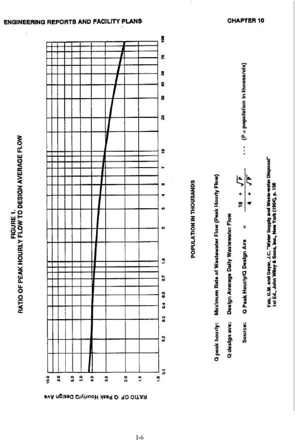
8 industrial uses. Projected wastewater flows for a community could be calculated by using 80 percent of the actual water consumption. Allowances shall be made for infiltration, inflow and significant commercial/ industrial waste flows which will be added to the per capita flow rate. If no actual data on infiltration is available, an assumed infiltration design allowance for existing sewers should be added to the design flow. For existing systems, the minimum infiltration design allowance for the existing sewers and service lines shall be no less than 200 gallons per inch of pipe diameter per mile of pipe per day. The department recommends that actual flow measurements to determine infiltration rates be conducted for those communities that have collector sewers that lie below the groundwater table. 3. Design Flows a. Average Daily Flow: This rate is determined by totaling all of the average flows for existing contributing sources based on a 24-hour period in which these flows are all generated during dry weather conditions. This rate is generally used to determine items such as costs, solids loading and organics loading. b. Minimum Flow: This rate will be based on 50 percent of the average daily flow if flow measurements are not available. c. Design Average Flow: This rate is determined to be the total of the projected population design domestic flow, additional maximum design wastewater flow from commercial/industrial plants, existing inflow and groundwater infiltration during wet weather flows. d. Peak Design: This rate is generally used to determine hydraulic sizing and mass loading of treatment units by multiplying a factor of 2.0 to 2.5 times the design average flow rate. e. Peak Hourly Flow: This rate shall be the ratio of peak diurnal flow to daily average flow shall be multiplied times the daily average flow as determined by Figure 1. Use of other values for peak hourly flow will be considered if justified on the basis of extensive documentation. The design for various components of the wastewater collection system (collector sewers, interceptor sewers, pumping stations) will be based on peak hourly flow. Force mains from pumping stations will be sized to handle the pumping capacity of the station. The design for various components of the treatment plant will be based upon either peak design flow or peak hourly flow. Generally, the organic loading of a wastewater treatment unit is based on the design average flow and the hydraulic loading of a unit is based on the peak design flow. Where recirculation is provided, the recirculation rate shall be added as required. The design criteria for each flow rate will be designated in the Chapter pertaining to that particular unit or component. I-4

9 4. New Process or Equipment - Consideration should be given whenever a new process or equipment is involved in the design, documentation of reliability and applicability in full-scale operations is recommended. Consideration should also be given to the availability of maintenance services or a convenient alternative in the event of mechanical failures. When an existing treatment works is to be upgraded or expanded, the component parts of the facility should be arranged for convenience of operation and maintenance, flexibility, economy and continuity of equipment. 5. Safety - All mechanical and treatment units should have adequate safety provisions for the personnel concerning occupational health and physical safety. I-5

10 I-6
11 CHAPTER II: Recommended Design Criteria For Sewers A. Engineer's Report, Plans, and Specifications B. Types of Sewers 1. Community 2. House 3. Industrial C. Design Period D. Design Factors E. Design Basis 1. Per Capita Flow 2. Alternate Method F. Gravity Sewer Design and Construction 1. Minimum Size 2. Depth 3. Slope 4. Alignment 5. Increasing Size 6. High Velocity Protection 7. Materials, Trenching and Installation 8. Joints and Infiltration 9. Calculations G. Manholes 1. Location 2. Cleanouts 3. Drop Type 4. Diameter 5. Flow Channel 6. Watertightness 7. Safety and Vandalism H. Inverted Siphons I. Stream Crossings 1. Cover Depth 2. Alignment 3. Materials 4. Sediment and Erosion Control J. Aerial Crossings K. Outfalls L. Sewer Extension M. Protection of Water Supplies 1. Water Supply Interconnections 2. Relation to Water Works Structures 3. Relation to Water Mains N. Small Diameter Gravity Sewers 1. General Statement 2. Administrative Provisions II-1

12 3. Small Diameter Gravity Sewer Design O. Storm Sewers P. Deviations from Design Criteria II-2

13 CHAPTER II RECOMMENDED DESIGN CRITERIA FOR SEWERS A. Engineer's Report, Plans, and Specifications Information for sewer systems must be submitted as required by Chapter 10, Recommended Standards for Wastewater Works, 1978 or the latest edition. B. Types of Sewers 1. Community Sewers - In general, and except for special reasons, the Department will approve plans for new systems, extensions, or replacement sewers only when designed upon the separate plan, in which rain water from roofs, inflow from streets and other areas, and groundwater from foundation drains is excluded. "Combined" sewers are not permitted unless provisions have been made for directing and treating the overflows. 2. House Sewers - House sewers conveying raw wastewater to public sewers should meet all requirements of the State Plumbing Code and the plumbing code of the local authority having jurisdiction, as well as the following: a. They shall be of asbestos cement, plastic, cast iron, concrete, vitrified clay or other material of 1,200 pound crush strength or heavier. b. They shall have a nominal inside diameter of not less than four inches. c. House sewer joints and connections to public sewers should be watertight and root proof. d. House sewers should be laid on a slope of 1/4 inch per foot and in no case less than 1/8 inch per foot. e. House sewers shall not be directly connected to manholes. f. Abandoned disposal systems shall be disconnected from buildings and plugged. All receptacles or excavations in which such receptacles were contained shall be filled with earth. Prior to filling, receptacle contents shall be pumped out and disposed of in a manner to eliminate pollution. 3. Industrial Sewers - Any industrial hook-ups; such as restaurants, rendering plants and service stations should have adequate pretreatment facilities for grease and grit collection in order to prevent clogging of collection lines and wear of components in discharge lines. C. Design Period - Refer to Chapter I. D. Design Factors II-3

14 In determining the required capacities of sanitary sewers, the following factors should be considered: 1. Peak hourly wastewater flow from residences. 2. Additional maximum wastewater flow from industrial plants and institutions. 3. Groundwater infiltration and inflow. 4. Capacity of pumps in wastewater pumping stations. E. Design Basis 1. Per Capita Flow - New sewer systems shall be designed on the basis of an average daily per capita flow of wastewater of not less than 100 gallons per day. This figure is assumed to cover a small amount of infiltration, but an additional allowance should be made where a large amount of infiltration is present. a. Design capacity for laterals and sub-mains - Full running capacity of not less than 4 times the design average daily flow per capita per day. b. Design capacity for large sewers - Full running capacity of not less than 2.5 times the design average daily flow per capita per day or peak hourly flow, whichever is greater. 2. Alternate Method - If water consumption records are available, refer to Chapter I. When deviations from the foregoing per capita rates are demonstrated, a description of the procedure used for sewer design shall be included. F. Gravity Sewer Design and Construction 1. Minimum Size - No community sewer receiving raw wastewater shall be less than six inches in diameter, however, eight inch diameter sewers are recommended. Six inch diameter pipe may be used as laterals where there are relatively low flows, a small number of people to be served, future extensions not anticipated and the sewer is capable of handling the design flows. The justification for using the six-inch pipe shall be provided by the consultant. The operating authority shall be made aware of the added possibility of cleaning problems which shall require their acceptance of any additional maintenance. Sewers receiving treated or partially treated wastewater and capable of handling the design flows may be four inches in diameter where adequate justification and documentation is provided. See Section N in this Chapter for EPA funded projects criteria. 2. Depth - Gravity sewers should be placed deep enough to serve all basements, assuming a 2 percent grade on house sewers (absolute minimum of 1 percent). They should be well below the frost line at all points and lower than any water lines placed in the same street. Where II-4

15 freezing conditions could occur, sewer lines should be provided with sufficient insulation or a raised berm for cover. 3. Slope - a. All sewers shall be so designed and constructed to give mean velocities, when flowing full, of not less than 2.0 feet per second, based on Manning's formula using an "n" value of Based on an "n" value of 0.013, the following are the minimum slopes which should be provided; however, slopes greater than these are desirable: Sewer Minimum Slope Ft/100 feet 4 inch inch inch inch inch inch inch inch inch inch inch inch inch inch b. Depending on the type of pipe, other practical "n" values may be permitted by the Department if deemed justifiable on the basis of research or field data presented. Slopes slightly less than those required for the 2.0 feet per second velocity when flowing full may be permitted. Reduced slopes will be permissible if a minimum velocity of 1.8 feet per second can be maintained and if detailed justifiable reasons are given; such as, a sewer serving a limited area or the elimination of a sewage lift station. Such decreased slopes will only be considered where the depth of flow will be 0.3 of the diameter or greater for design average flow. Whenever such decreased slopes are selected, the design engineer must furnish with his report his computations of the depths of flow in such pipes at minimum, average, and daily or hourly rates of flow. The operating authority shall be made aware that decreased slopes may cause additional sewer maintenance expense and septic conditions. Sewer size shall be based on design flows and not the grade that is available. c. Sewers shall be laid with uniform slope between manholes. d. Sewers on 20 percent slope or greater shall be anchored securely with concrete anchors or equal, spaced as follows: 1) Not over 36 feet center to center on grades 20 percent and up to 35 percent. 2) Not over 24 feet center to center on grades 35 percent and up to 50 percent. II-5

16 3) Not over 16 feet center to center on grades 50 percent and over. 4. Alignment - Sewers 24 inches or less shall be laid with straight alignment between manholes except where street or road layouts are such that straight alignment between manholes is impractical, sewers may be curved to conform with their curvature. The radius of curvature shall not be less than 100 feet and the deflection angle shall not exceed the manufactures recommendations at any joint or point on the pipe. It is suggested that the sewer curvature be made concentric with the street curvature to simplify layout work and locating the lines at a later date. An alignment test such as "balling" must be conducted on curved sewers. The entity responsible for maintenance should be cognizant of the fact that additional maintenance may be necessary and small diameter sewers will require jet-cleaning machines. 5. Increasing Size - When a smaller sewer joins a larger one, the invert of the larger sewer should be lowered sufficiently to maintain the same energy gradient. An approximate method for securing these results is to place the 0.8 depth of flow point of both sewers at the same elevation. Generally, sewers should not decrease in size in the downstream direction. 6. High Velocity Protection - Where velocities greater than 15 feet per second are attained, sewers shall be anchored securely with concrete anchors or equal to protect against displacement by erosion and shock. The design shall be such to prevent turbulence and deterioration of the receiving manhole. 7. Materials, Trenching and Installation - Any generally accepted material for sewers will be given consideration, but the material selected should be adapted to local conditions, such as character of industrial wastes, possibility of septicity, soil characteristics, exceptionally heavy external loadings, abrasion and similar problems. Installation specifications shall contain appropriate requirements based on the criteria, standards and requirements established by industry in its technical publications. Requirements shall be set forth in the specifications for the pipe and methods of bedding and backfilling thereof so as not to damage the pipe or its joints, impede cleaning operations and future tapping, nor create excessive side fill pressures or ovalation of the pipe, nor seriously impair flow capacity. The design engineer should consult the various ANSI and ASTM specifications or industry literature for information on pipe bedding classes for each pipe material used in the design. When trenching, all rock shall be removed within 6 inches of the pipe. The trench shall be dewatered for all work. Open trench time should be considered and all pipe ends plugged when installation of pipe is halted. In all cases, suitable backfill or other structural protection shall be provided to preclude settling and/or failure of the higher pipe. Backfill shall not contain debris, frozen material, large clods or stones, organic matter or other unstable material. Stones larger than 3 inches in diameter shall not be placed within 2 feet of the top of the pipe. Compaction shall be to a density at least equal to the surrounding soil or existing roadway conditions. II-6

17 All sewers shall be designed to prevent damage from superimposed loads. Proper allowance for loads on the sewer shall be made because of the width and depth of trench. When standard strength sewer pipe is not sufficient, the additional strength needed may be obtained by using extra strength pipe or by special construction. Deflection tests shall be performed on pipe after final backfill has been in place at least 30 days. No pipe shall exceed a deflection of 5%. 8. Joints and Infiltration - The method of making joints and materials used should be included in the specifications. Sewer joints shall be designed to minimize infiltration and to prevent the entrance of roots. Leakage tests shall be specified. This may include appropriate water or low pressure air testing. The leakage outward or inward (exfiltration or infiltration) shall not exceed 200 gallons per inch of pipe diameter per mile per day for any section of the system. The use of a television camera or other visual methods for inspection prior to placing the sewer in service is recommended. 9. Calculations - Computations should be presented, in a tabular form, to indicate depths and velocities at minimum, design average and peak hourly waste flow for the different sizes of sewers proposed. G. Manholes 1. Location - Unless necessary, manholes should not be located in drainageways. If any flooding over manholes is anticipated; they shall be provided with watertight covers. Manholes shall be installed at the end of each line; at all changes in grade, size, or alignment; at all intersections; and at distances not greater than 400 feet for sewers 15 inches or less, and 500 feet for sewers 18 inches to 30 inches, except that distances up to 600 feet may be approved in cases where adequate cleaning equipment for such spacing is provided. Greater spacing may be permitted in larger sewers and in those carrying a settled effluent. The distance between manholes for sewers less than 15 inches in diameter may be increased to 450 feet if justification is provided by the consultant. 2. Cleanouts - Cleanouts may be used only for special conditions and shall not be substituted for manholes nor installed at the end of laterals greater than 150 feet in length. Cleanouts shall be provided on all service lines in accordance with State Plumbing Code. The cleanout shall be constructed using a 45 degrees bend directed downstream on vertical riser pipe to the surface. Size of the cleanout shall be the same as the pipe size. 3. Drop Type - A drop pipe shall be provided either inside or outside for a sewer entering a manhole at an elevation of 24 inches or more above the manhole invert. Where the difference in elevation between the incoming sewer and the manhole invert is less than 24 inches, the invert should be filleted to prevent solids deposition. II-7

18 Inside drop connections shall be secured to the interior wall of the manhole and provide adequate access for cleaning. For exterior drop connections, the entire outside drop connection shall be encased in concrete. 4. Diameter - The minimum diameter of manholes shall be 48 inches. The size of the manhole access shall be 22 inches or larger in diameter. 5. Flow Channel - The flow channel through manholes should be made to conform in shape and slope to that of the sewers. 6. Watertightness - The specifications shall include a requirement for inspection of manholes for watertightness prior to placing into service and shall not exceed leakage limits for sewers. Watertight manhole covers or raised manhole frames and covers are to be used wherever the manhole tops may be flooded by street runoff or high water. Manholes of brick or segmented block should be waterproofed on the exterior with plaster coatings; supplemented by a bituminous waterproof or epoxy coating where groundwater conditions are unfavorable. 7. Safety and Vandalism - It is recommended that entrance into manholes contain provisions for portable ladders. Consideration should be given for providing a means of ventilation for deep manholes. Locked manhole covers may be desirable where vandalism or unauthorized dumping may be a problem. H. Inverted Siphons Inverted siphons shall require at least two barrels, with a minimum pipe size of six inches and shall be provided with necessary appurtenances for convenient flushing and maintenance; the manholes shall have adequate clearances for rodding; and in general, sufficient head shall be provided and pipe sizes selected to secure velocities of at least 3.0 feet per second for average flows. The inlet and outlet details shall be designed to permit the normal flow to be diverted to one barrel while the other barrel may be taken out of service for cleaning. The joints should not exceed 45 degrees bends to easily accommodate cleaning equipment. I. Stream Crossings 1. Cover Depth - The top of sewers when entering or crossing streams shall be at a sufficient depth below the natural stream bed to protect the sewer line. The following cover requirements should be met: a. One foot of cover where the sewer is located in rock. b. Three feet of cover or more is required in other material depending on size of stream. c. In paved stream channels, immediately below the pavement. II-8

19 d. Shallow and intermittent streams may require insulating materials. 2. Alignment - Sewers crossing streams should be designed to cross the stream as nearly perpendicular as possible with no change in grade. 3. Materials - Sewers entering or crossing streams shall be constructed of cast or ductile iron pipe with mechanical joints or other watertight materials, encasements, and anchored so no changes in alignment or grade will occur. 4. Sediment and Erosion Control a. Refer to Department Guide, BMP's "Best Management Practices". b. "404" Permit for large streams. J. Aerial Crossings 1. Supports shall be provided to maintain the alignment and support of pipe along the aerial crossing. 2. Precautions against freezing, such as insulation and increased slope, shall be provided. Expansion jointing shall be provided for sections of pipes entering the below-ground sewers. 3. Consideration shall be given to floating debris and flood waters. The pipe should be no lower than the elevation of a hundred year (100) flood. K. Outfalls 1. Outfall sewers and structures shall be designed and constructed to provide: a. Protection of the sewer against excessive receiving stream velocities, waves, floating debris, or other hazards which may damage the outfall works. b. Protection of the sewer from entrance of floodwater. c. Protection of the sewer from entrance of wildlife. d. Compliance with mixing zone criteria established in A.R.S.D. 74:03:02:07. L. Sewer Extension In general, sewer extensions shall be allowed only if the receiving wastewater treatment facility is either: 1. Capable of handling the added hydraulic load and pipe size not smaller. II-9

20 2. Capable of adequately processing the added hydraulic and organic load. 3. Provision of adequate treatment facilities on a time schedule acceptable to the Department is assured. M. Protection of Water Supplies 1. Water Supply Interconnections - There shall be no physical connection between a public or private potable water supply system and a sewer, or appurtenance thereto, which would permit the passage of any sewage or polluted water into the potable water system. Water main bleeders into sanitary sewers are prohibited. No water pipe shall pass through or come in contact with any part of a sewer manhole. 2. Relation to Water Works Structures - While no general statement can be made to cover all conditions, sewers shall be at least 75 feet from shallow water supply wells, 50 feet from underground water reservoirs and 30 feet from a well if the sewer is constructed as mentioned in section M-3-c. 3. Relation to Water Mains a. Horizontal Separation - Whenever possible, sewers should be laid at least 10 feet, horizontally, from any existing or proposed water main. Should local conditions prevent a lateral separation of 10 feet, a sewer may be laid closer than 10 feet to a water main if: 1) It is laid in a separate trench; or 2) It is laid in the same trench with the water main located at one side on a bench of undisturbed earth; 3) In either case, the elevation of the crown of the sewer is at least 18 inches below the invert of the water main. b. Vertical Separation - Whenever sewers must cross under water mains, the sewer shall be laid at such an elevation that the top of the sewer is at least 18 inches below the bottom of the water main. When the elevation of the sewer cannot be buried to meet the above requirement, the water main shall be relocated to provide this separation and reconstructed with slip-on or mechanical-joint cast-iron pipe, asbestos-cement pressure pipe or prestressed concrete cylinder pipe for a distance of 10 feet on each side of the sewer. One full length of water main should be centered over the sewer so that both joints will be as far from the sewer as possible. c. Special Conditions - When it is impossible to obtain the proper horizontal and vertical separation as stipulated above, the water main should be constructed of slip-on or mechanical-joint cast-iron pipe, asbestos-cement pressure pipe or prestressed concrete cylinder pipe and the sewer constructed of mechanical-joint cast-iron pipe, schedule 40 ABS or PVC or equal and both services should be pressure tested to assure watertightness II-10

21 in accordance with AWWA standard for leakage testing. As an alternative, it is permissible to encase either the water or the sewer main with six (6) inches of concrete for a distance of 10 feet on each side of the crossing; or if PVC or cast iron is used as encasement material, the ends shall be adquately sealed with concrete as well as any joints within the 20 foot section. d. House Sewers - The requirements in sections M-3-a, M-3-b, and M-3-c shall apply to building sewers and water service lines to buildings except that the separations mentioned in sections M-3-a and M-3-b may be reduced to state plumbing code when water lines are installed with continuous non-jointed material. N. Small Diameter Gravity Sewers 1. General Statement - The innovative and alternative technology provisions of the Municipal Wastewater Treatment Construction Grant Amendments of 1981 (Public Law ) provide for additional Federal grant funding for eligible costs associated with small diameter gravity sewers serving small communities and conveying partially or fully treated wastewater. Septic tank effluent is considered partially treated wastewater, and the costs for design and construction of treatment works which collect and convey it for additional centralized treatment are eligible for additional Federal grant funding, provided that all requirements in this section are met. 2. Administrative Provisions - Alternative technology grant funding for those costs associated with the transport of partially or fully treated wastewater may be provided only if the project serves a small community defined as follows: a. A small community is defined by 40 CFR (40) as any municipality with a population of 3,500 or less or highly dispersed sections of larger municipalities as determined by the U.S. EPA Regional Administrator. b. If nonconventional systems are planned for certain sparsely developed subdivisions or parcels of a larger municipality (existing population over 3,500), then each of these subdivisions or parcels could be defined as a small community for the purpose of alternative system funding. Any such area having a density of two households per acre or less could be considered sparsely populated. 3. Small Diameter Gravity Sewer Design Criteria - The following considerations shall be used for the design of small diameter gravity sewer systems: a. No gravity sewer shall be less than 4 inches in diameter. b. Since the small diameter gravity sewers will be conveying anaerobic septic tank effluent which will be corrosive and odorous, the pipe, pumping equipment and treatment hardware shall be manufactured of suitable materials to endure these adverse conditions. Acceptable pipe materials are ABS, PVC, poly- ethylene, vitrified clay and fiberglass/ polyester II-11
22 composite. Concrete, asbestos cement, steel, iron and other metals are not acceptable. Bituminous-fiber pipe, commonly known as Orangeburg pipe, is not acceptable for public or community collection systems. c. The maximum allowable infiltration-exfiltration rate shall be 200 gallons per inch of pipe diameter per mile per day. d. Small diameter gravity sewers conveying partially or fully treated wastewater will be considered acceptable if they are designed and constructed to provide mean velocities, when flowing full, of not less than 1.5 feet per second based on Manning's formula using an "n" value of The following slopes should be provided, however, slopes greater than specified are desirable: Minimum Slope Sewer Size Ft/100 feet 4 inch inch inch 0.19 While insufficient empirical data has been generated to demonstrate the absolute, unqualified acceptability of slopes less than those specified in the preceding paragraph, a system of small diameter gravity sewers conveying settled sewage may be approved if designed and constructed to provide mean velocities, when flowing full, of not less than 1.0 feet per second based on Manning's formula using an "n" value of 0.013, provided that the cost saving qualification of 40 CFR (4) is met. The purpose of this is to ensure that the savings to be gained by installing the sewers at these flatter slopes is sufficient to justify the potential risk involved. Under these criteria, the minimum slopes which should be provided: Minimum Slope Sewer Size Ft/100 feet 4 inch inch inch 0.08 It is imperative that septic tanks be properly sized and septic tank maintenance procedures be established to ensure the retention of solids in the septic tanks. While important for flows at 1.5 feet per second, it is especially important below that velocity. e. It is preferable that cleanouts and manholes be alternated at a spacing of approximately 200 to 250 feet; however, cleanouts will be allowed at deadends and intervals of 300 feet where long sections of pipe can be installed. Manholes should be provided at the junctions of two or more small diameter gravity sewer lines. Manhole and cleanout covers should be watertight and consideration given for vandalism due to grit and inflow problems experienced with conventional covers. Manholes and cleanouts should be located where they will be least susceptible to damage from street grading and snowplowing. II-12
23 f. Drop type manholes should be avoided where anaerobic conditions exist. Gases generated in the septic tank under anaerobic conditions may be toxic; consequently, the creation of turbulence will enhance the release of gases from the septic tank effluent. g. Special consideration should be given to protect the sewer against freezing due to construction at ground depths susceptible to frost penetration because the outlet piping of the septic tank is normally shallower than that of conventional gravity building sewers. h. If severe odor problems are anticipated, peroxide feed stations may be considered for control of odors. i. Since it is recognized that the key technology to successful operation of these systems is retention of solids in the septic tank, maintenance districts and cleaning procedures for septic tanks shall be established in conjunction with the facility planning and design phases. Sewer use ordinances and/or local health codes shall include adequate provisions to ensure proper operation, use, connection to, and construction of such small diameter sewers. Adequate cleaning equipment, such as a jet machine, shall be provided or through agreement with another entity, be readily available. O. Storm Sewer 1. Protection of Water Supplies Storm sewers shall be constructed to meet the requirements of section M of this chapter, with the following exception: a reinforced concrete pipe (RCP) storm sewer may cross below a water main with the separation of less than 18 inches or at any height above a water main provided the joints on the RCP that are within 10 feet of either side of the watermain are assembled with preformed butyl rubber sealant meeting federal specification #SS-S-210A and AASHTO M0198, and each of these joints are encased with a minimum 2-foot wide by 6-inch thick concrete collar centered over the joint and re-enforced with the equivalent steel area as that in the RCP; the watermain will not be required when the RCP joints are collared within the 20- foot section. 2. Pipe Sizing To ensure any debris which enters a drain is carried through the system to the outlet, pipe sizes should not decrease in the down-stream direction even though increased slope may provide adequate capacity in the smaller pipe. 3. Inlet/Outlet Protection Consideration should be given, especially with large diameter pipe, to providing trash guards or grid work over inlets and outlets to prevent obstructions from debris and as a safety measure to prohibit entry. II-13
24 4. Erosion Protection Erosion protection shall be required at the discharge outlet when the slope gradient and pipe discharge capacity are expected to reach erosion velocity for the existing soil conditions. P. Deviations from Design Criteria The Department may consider and allow deviations where adequate documentation is provided to prove the need for such deviation. II-14
25 II-15
26 CHAPTER III: Recommended Design Criteria For Sewage Pumping Stations, Force Mains And Pressure Sewers A. Engineer's Report, Plans and Specifications 1. Contributary Area 2. Location 3. Design Data B. General 1. Flooding- 2. Grit 3. Security C. Design 1. Capacity of Pumps 2. Type 3. Structures D. Pumps and Pneumatic Ejectors E. Controls F. Valves G. Wet Wells H. Ventilation I. Flow Measurement J. Water Supply K. Suction-Lift Pump Stations 1. Priming 2. Capacity L. Submersible Pump Stations 1. Pump Removal 2. Operation 3. Minimum Draw Down 4. Controls 5. Valves 6. Electrical Equipment M. Alarm Systems N. Emergency Operation 1. Objective 2. Emergency Power Supply 3. Internal Combustion Equipment 4. Portable Equipment 5. Emergency Power Generation O. Overflows P. Instructions and Equipment Q. Force Mains 1. Size 2. Velocity - 3. Valves - 4. Termination III-1
27 5. Leakage (Ex-filtration) - 6. Maintenance 7. Restraints R. Pressure Sewer System 1. General 2. Design Criteria S. Deviations from Design Criteria III-2
28 CHAPTER III RECOMMENDED DESIGN CRITERIA FOR SEWAGE PUMPING STATIONS, FORCE MAINS AND PRESSURE SEWERS A. Engineer's Report, Plans and Specifications Information for sewage pumping stations must be submitted as required by Chapter 10, Recommended Standards for Sewage Works, 1978 or latest Edition. In addition, the following information is requested: 1. Contributary Area - A description of the extent of the existing and proposed contributary area with reference to a general system map as well as a description of probable future expansion of the contributary area is requested. 2. Location - The proposed pumping station, force main and point of discharge into the existing sewer system shall be shown on a map. In addition, the report shall discuss the capacity available in the existing downstream sewer, its ability to convey the additional flow and the effect it will have on the treatment facility. 3. Design Data - The design data for the proposed project should include the following: a. Design Period. b. Population densities per acre and total population served. c. Area served in acres. d. Per capita sewage contribution expressed as an average daily and as a peak hourly value. e. Infiltration and inflow and method used to establish. f. Industrial wastes contribution. g. Design flow rates expressed as design average daily and peak hourly values. B. General 1. Flooding - Sewage pumping stations shall not be subject to flooding. It is important that the stations be readily accessible and fully operational during a twenty-five (25) year flood. A one hundred (100) year flood recurrence interval should be considered in the design for protection of structure and electrical and mechanical equipment from physical damage. The stations shall be readily accessible; preferably located off the traffic ways of streets and alleys. III-3
29 2. Grit - Where it may be necessary to pump sewage prior to grit removal, the design of the wet well should receive special attention and the discharge piping shall be designed to prevent grit settling in the discharge lines of pumps not operating. 3. Security - Pumping stations shall be designed with security and lighting to discourage vandalism. C. Design The following items should be given consideration in the design of sewage pumping stations: 1. Capacity of Pumps - The pumps shall have sufficient capacity to pump at least four times the design average flow rates for laterals and sub-main sewers; either two and one-half times the design average flow rate or peak hourly flow rate, whichever is greater, for main, trunk and interceptor sewers. Each pump shall be capable of handling peak sustained flow rates. If no peak hourly flow data is available, refer to Figure 1 in Chapter Type - Sewage pumping stations that are of the dry well type are the most desirable; however, circumstances will generally justify the use of submersible- type pumps. 3. Structures a. Wet and dry wells including their superstructures shall be completely separated. b. Provision shall be made to facilitate and easily remove pumps and motors. c. Suitable and safe means of access shall be provided to dry wells of pump stations and shall be provided to wet wells containing either bar screens or mechanical equipment requiring inspection or maintenance. Stairways should be provided for installations deeper than 15 feet and should be installed with rest landings not to exceed 10 foot vertical intervals. A manlift or elevator may be used in lieu of landings, provided emergency access is included in the design. d. Due consideration shall be given to the selection of materials because of the presence of hydrogen sulphide and other corrosive gases, greases, oils and other constituents frequently present in sewage. Structure materials may require cathodic and anodic protection. e. Where a bar rack is provided, a mechanical hoist shall also be provided. The hoist and accessories shall be rated for not less than 1.5 times the heaviest anticipated load. f. The pumping station compartments shall resist hydrostatic uplift pressures. D. Pumps and Pneumatic Ejectors III-4
30 1. At least two pumps or pneumatic ejectors shall be provided. Where the pumping installation will serve not more than 50 homes, a single unit will be permitted, provided that the station is designed to permit the installation of a future duplicate unit with no structural changes. A minimum of 3 pumps should be provided for stations handling flows greater than one (1) million gallons per day (mgd). If only two units are provided, they should have the same capacity. Each shall be capable of handling flows in excess of the expected peak hourly flow. Where three or more units are provided, they should be designed to fit actual flow conditions and must be of such capacity that with any one unit out of service the remaining units will have capacity to handle peak sewage flows. It is preferable that a standby pump or ejector be provided and available for service at all times. 2. Pumps handling raw sewage should be preceded by readily accessible bar racks with clear openings not exceeding 2 1/2 inches, unless pneumatic ejectors are used or special devices, such as, grinders, are installed to protect the pumps from clogging or damage. Where the size of installation warrants, a mechanically cleaned bar screen with grinder or comminution device is recommended. Where screens are located below ground, convenient facilities must be provided for handling screenings. For the larger or deeper stations, duplicate protection units of proper capacity are preferred. 3. Pumps or ejectors shall be capable of passing spheres of at least 3 inches in diameter. Pump suction and discharge openings shall be at least 4 inches in diameter. Turned-down bellmouth inlets are preferred. The pumps and ejectors should have non-corrosive materials for inner parts. Where turned-down bellmouth inlets are used, the bell should be not more than D/2 and not less than D/3 above the floor of the wet well. It is recommended that sump and approach channel dimensions be provided as suggested by the pump manufacturer. 4. The pump shall be so placed that under the normal operating conditions it will operate under a positive suction head, except as specified in Section K Electrical systems and components (e.g. motors, lights, cables, conduits, switchboxes, control circuits, etc.) in enclosed or partially enclosed spaces where flammable mixtures occasionally may be present (including raw sewage wet wells) shall comply with the National Electrical Code requirements for Class I, Division I, Groups C and D locations. When such equipment is exposed to weather it shall meet the requirements of weatherproof equipment (Nema 3R). 6. Each pump should have an individual intake. Wet well design should be such as to avoid turbulence near the intake. Intake piping should be as straight and short as possible. 7. A separate sump pump equipped with dual check valves shall be provided in the dry wells to remove leakage or drainage with the discharge above the overflow level of the wet well. A connection to the pump suction is also recommended as an auxiliary feature. Water ejectors connected to a potable water supply will not be approved. All floor and walkway surfaces should have an adequate slope to a point of drainage. III-5
OAR52 A-1 (September, 1981)
") APPENDIX A SEWER PIPELINES (1) MINIMUM REQUIREMENTS FOR SEWER - PIPELINES (a) Capacity: Sewers shall be of such diameter as to pass without overflow, bypass, or back flow onto damageable property of a
APPENDIX A SEWER PIPELINES (1) MINIMUM REQUIREMENTS FOR SEWER - PIPELINES (a) Capacity: Sewers shall be of such diameter as to pass without overflow, bypass, or back flow onto damageable property of a
SECTION 5: SANITARY SEWER SYSTEM DESIGN
 SECTION 5: SANITARY SEWER SYSTEM DESIGN 5.01 GENERAL Sanitary sewer improvements shall be designed to serve the ultimate level of City development as defined in the General Plan and the Wastewater Facilities
DIVISION OF WATER QUALITY CONSTRUCTION GRANTS & LOANS SECTION FAST TRACK AUDIT CHECKLIST
 DIVISION OF WATER QUALITY CONSTRUCTION GRANTS & LOANS SECTION FAST TRACK AUDIT CHECKLIST CERTIFICATION 1. Did the engineer submit a certificate of completion utilizing the appropriate page of the issued
SANITARY SEWER SPECIFICATIONS
 SANITARY SEWER SPECIFICATIONS OCTOBER 2003 HARVEST-MONROVIA WATER, SEWER, AND FIRE PROTECTION AUTHORITY SECTION 1.00 1.10 Purpose The purpose of this document is to assemble the sewer specifications, policies,
Minimum Design Criteria for the permitting of Gravity Sewers
 Minimum Design Criteria for the permitting of Gravity Sewers Adopted by the Division of Water Quality on February 12, 1996 Updated to 15A NCAC 2T Regulations on March 2008 1,400 copies of this document
ARTICLE II (2) ARTICLE II - REQUIRED USE OF PUBLIC SEWERS. PARAGRAPH 020001 Purpose and Application.
 ARTICLE II - REQUIRED USE OF PUBLIC SEWERS. PARAGRAPH 020001 Purpose and Application.") ARTICLE II - REQUIRED USE OF PUBLIC SEWERS. PARAGRAPH 020001 Purpose and Application. Article II provides rules governing the allowable connection to the City POTW and the construction and inspection of
ARTICLE II - REQUIRED USE OF PUBLIC SEWERS. PARAGRAPH 020001 Purpose and Application. Article II provides rules governing the allowable connection to the City POTW and the construction and inspection of
SECTION 3 SANITARY SEWER DESIGN
 SECTION 3 SANITARY SEWER DESIGN 3.1 GENERAL DESIGN CRITERIA 3.1.1 Requirement for Sanitary Sewer 3.1.2 Design Approval 3.1.3 IEPA Permit Required 3.1.4 Differentiation Between Public and Private Sanitary
SECTION 6 SANITARY SEWER MAIN 6.01 SCOPE
 6.01 SCOPE The work covered by this section of the specifications consists of the furnishing of all plant, labor, materials, equipment and supervision and performing all operations involved in the construction
PART 6 - STANDARD DESIGN AND CALCULATION FORMS 6.1 SANITARY SEWER DATA SHEET
 PART 6 - STANDARD DESIGN AND CALCULATION FORMS 6.1 SANITARY SEWER DATA SHEET Name of Municipality or Sewer District Name of Project Original Township and Lot Number Name of Engineer of Firm Preparing Plans
Chapter 9 Sanitary Sewers
 Chapter 9 Sanitary Sewers S:/Engineering/Design Standards/Chapter 9 12/29/2014 Section 9.1 Topic General Requirements Chapter 9 Sanitary Sewers Page 9-1 9.2 Plan Submittals 9-1 9.3 Determination of Flow
SECTION 08000 STORM DRAINAGE TABLE OF CONTENTS
 SECTION 08000 STORM DRAINAGE 08010 DESIGN A. Location B. Sizing TABLE OF CONTENTS 08020 MATERIALS A. Pipe Materials B. Structure Materials C. Installation D. Inlets and Outlets 08030 INSPECTIONS AND TESTING
Exhibit A. Rules and Regulations for House Connections and Sewer Extensions
 The purpose of this application example is to provide assistance to small and medium sized rural communities in the drafting of documents necessary for the efficient operation of water, wastewater, and
The checklist utilized by the Authority will be similar to that which is shown below. Project Name: Location: Consulting Engineering Firm:
 Page 1 of 6 Section 1. PURPOSE This policy is an Engineering checklist of the Local Review Program for sanitary sewer improvement projects by the Bedford Regional Water Authority ( Authority ). Section
SECTION 33 41 13 PUBLIC STORM UTILITY DRAINAGE PIPING
 SECTION 33 41 13 PUBLIC STORM PART 1 - GENERAL 1.01 SECTION INCLUDES A. Storm drainage piping, fittings, and accessories at proposed station areas and locations other than under and immediately adjacent
Stormwater/Wetland Pond Construction Inspection Checklist
 : Construction Inspection ChecklistsTools Stormwater/Wetland Pond Construction Inspection Checklist Project: Location: Site Status: Date: Time: Inspector: SATISFACTORY/ UNSATISFACTORY COMMENTS Pre-Construction/Materials
CHAPTER 6 SEWER SYSTEM DESIGN STANDARDS
 CHAPTER 6 SEWER SYSTEM DESIGN STANDARDS TABLE OF CONTENTS CHAPTER 6 SEWER SYSTEM DESIGN STANDARDS 6.00 Objective Page 1 6.01 Additional Referenced Standards Page 2 6.02 Special Design Problems Page 2 6.03
CHAPTER 11 STORM DRAINAGE
 CHAPTER 11 STORM DRAINAGE SECTION 11 GENERAL 11.1 Scope. The provisions of this chapter shall govern the materials, design, construction and installation of storm drainage. 11.2 Where required. All roofs,
DESCRIPTION OF STORMWATER STRUCTURAL CONTROLS IN MS4 PERMITS
 DESCRIPTION OF STORMWATER STRUCTURAL CONTROLS IN MS4 PERMITS Phase I MS4 permits require continuous updating of the stormwater system inventory owned and operated by the MS4. They also include inspection
DIVISION 2 - SEWERAGE AND DRAINAGE SECTION 02720 - STORM DRAIN SYSTEMS PART 1 - GENERAL
 DIVISION 2 - SEWERAGE AND DRAINAGE SECTION 02720 - STORM DRAIN SYSTEMS PART 1 - GENERAL 1.01 DESCRIPTION A. Furnish and install all storm drains, including manholes, inlets, service lines and other appurtenant
Section 02702 SEWER PIPE INSTALLATION AND TESTING
 PART 1 - GENERAL Section 02702 SEWER PIPE INSTALLATION AND TESTING 1-1. SCOPE. This section covers the installation and testing of all sewer pipe furnished under the following specification sections: Concrete
32-02.05 Precast Manhole Sections and Castings. These items shall conform to Section 31, "Storm Drain Installation," of these Standard Provisions.
 SECTION 32: SANITARY SEWER INSTALLATION 32-01 SCOPE. The Work shall consist of furnishing and installing sewer mains, manholes, laterals, cleanout fittings and appurtenances; and testing, flushing and
See Appendix A for additional information, or contact ASTM directly.
 DEFINITIONS Wherever used in these specification guidelines, the following words and terms have the meanings indicated. AREAWAY: A paved surface, serving as an entry area to a basement or subsurface portion
Type of Sewer Systems. Solomon Seyoum
 Type of Sewer Systems Solomon Seyoum 0 Learning objectives Upon completion of this lecture, the participants will be able to differentiate between types of sewer systems and discuss different aspects of
CITY OF ST. CA THARINE S. cn- Olc.4 BY-LAW NO. WHEREAS the Council of the Corporation of the City of St. Catharines, is
 ~: ~,,' " CITY OF ST. CA THARINE S BY-LAW NO. cn- Olc.4 A By-law to regulate sanitary and storm drainage. WHEREAS the Council of the Corporation of the City of St. Catharines, is authorized by the provisions
Recommended Standards for Wastewater Facilities
 Table of Contents Recommended Standards for Wastewater Facilities 2004 Edition Policies for the Design, Review, and Approval of Plans and Specifications for Wastewater Collection and Treatment Facilities
The work of this Section includes furnishing and installing Reinforced Concrete Pressure Pipe as shown on the Drawings and as specified.
 Section 33 0200- Page 1 of 4 PART 1 - GENERAL 1.1 DESCRIPTION OF WORK The work of this Section includes furnishing and installing Reinforced Concrete Pressure Pipe as shown on the Drawings and as specified.
SEPTIC SYSTEMS. 1. Building sewer connects the building plumbing to the septic tank.
 SEPTIC SYSTEMS Who Has A Septic System? Approximately 30 percent of Connecticut s population is served by on-site subsurface sewage disposal systems (a.k.a. septic systems). This means a large percentage
3A-1---------------------------------General Information A. Concepts... 1 B. Conditions... 1
 Statewide Urban Design and Specifications Table of Contents Design Manual Chapter 3 Sanitary Sewers Table of Contents TOC Chapter 3 Sanitary Sewers 3A General Information 3A-1---------------------------------General
CHAPTER 17: STORM SEWER STANDARDS. 17.00 Introduction. 17.01 Administration. 17.02 Standards 17.1
 CHAPTER 17: STORM SEWER STANDARDS 17.00 Introduction 17.01 Administration 17.02 Standards 17.1 17.00 INTRODUCTION The purpose of this chapter is to provide guidance for the design and construction of storm
3. Contractor shall ensure that all permits are obtained prior to any construction. Contractor shall be responsible for all utility fees.
 The following shall serve as the minimum requirements for contractors performing work in relation to the Authority s potable water and sanitary sewer system(s), appurtenances and service connections. General:
Top 10+ Mistakes of DWV plumbing design
 Top 10+ Mistakes of DWV plumbing design Listed below are the some of the most frequently missed items, noticed by our inspectors, at plumbing rough-in when non-plumbers attempt plumbing design. Most of
AIR RELEASE, CLEANOUT, AND SEWER MANHOLES
 AIR RELEASE, CLEANOUT, AND SEWER MANHOLES **From Hartford IM BLDG(10) DESCRIPTION. This work shall consist of the construction of air release, cleanout, and sanitary sewer manholes; and the furnishing
Specifications for Residential Property Owners Connection to New Public Sewer
 Specifications for Residential Property Owners Connection to New Public Sewer Spalding Tract property owners are required to connect to the community sewer system when construction is complete and the
SECTION 33 31 00.11 GRAVITY SANITARY SEWERS
 SECTION 33 31 00.11 GRAVITY SANITARY SEWERS PART 1: GENERAL 1.01 SCOPE A. Gravity sanitary sewers and appurtenances. 1.02 SUBMITTALS A. Conform to requirements of Section 01 33 00 Submittals. B. Submit
Section 2100-Trenching and Tunneling
 SECTION 5200 - STORM SEWER PART 1 - GENERAL 1.01 SCOPE: This Section covers installation of storm sewer mains and culverts. Topics include permits and fees, trench widths, pipe laying, bedding, initial
Checklist for plans to Construct, Alter or Repair An Individual Subsurface Sewage Disposal System
 Checklist for plans to Construct, Alter or Repair An Individual Subsurface Sewage Disposal System An application for the construction or alteration of an individual subsurface sewage disposal system shall
DESIGN CRITERIA CONSIDERED IN THE REVIEW OF WASTEWATER TREATMENT FACILITIES POLICY 96-1
 DESIGN CRITERIA CONSIDERED IN THE REVIEW OF WASTEWATER TREATMENT FACILITIES POLICY 96-1 COLORADO DEPARTMENT OF PUBLIC HEALTH and ENVIRONMENT Water Quality Control Commission 4300 Cherry Creek Drive South
Chapter 3 CULVERTS. Description. Importance to Maintenance & Water Quality. Culvert Profile
 Chapter 3 CULVERTS Description A culvert is a closed conduit used to convey water from one area to another, usually from one side of a road to the other side. Importance to Maintenance & Water Quality
Collection Systems Technology Fact Sheet Sewers, Conventional Gravity
 United States Environmental Protection Agency Collection Systems Technology Fact Sheet Sewers, Conventional Gravity DESCRIPTION Sewers are hydraulic conveyance structures that carry wastewater to a treatment
CHAPTER 11 STORM DRAINAGE
 CHAPTER STORM DRAINAGE SECTION PC 0 GENERAL 0. Scope. The provisions of this chapter shall govern the materials, design, construction and installation of storm drainage. Storm water discharge shall be
Emerging Technologies in Wastewater Collection Systems
 Keville Enterprises Emerging Technologies in Wastewater Collection Systems Douglas McCutchen, CCM Brian Karmasin, P.E., BCEE CMAA Annual Conference Oct 2008 San Francisco, California Today s s Presentation
Texas Commission on Environmental Quality Page 1 Chapter 217 - Design Criteria for Domestic Wastewater Systems
 Texas Commission on Environmental Quality Page 1 217.31. Applicability. SUBCHAPTER B: TREATMENT FACILITY DESIGN REQUIREMENTS 217.31-217.39 Effective August 28, 2008 This subchapter details the design values
OVERVIEW OF SIDE SEWER REQUIREMENTS
 NOVATO SANITARY DISTRICT MARIN COUNTY, CALIFORNIA OVERVIEW OF SIDE SEWER REQUIREMENTS 2001 OVERVIEW OF SIDE SEWER REQUIREMENTS TABLE OF CONTENTS Section 1. GENERAL INFORMATION... 1 1-01 Jurisdiction...
COMBINED SEWER OVERFLOW OPERATIONAL AND MAINTENANCE PLAN SUMMARY
 COMBINED SEWER OVERFLOW OPERATIONAL AND MAINTENANCE PLAN SUMMARY Revised: April 2014 Village of Wilmette, Illinois NPDES CSO Permit No. ILM580012 Chapter 1 Introduction This Operational and Maintenance
Module 7: Hydraulic Design of Sewers and Storm Water Drains. Lecture 7 : Hydraulic Design of Sewers and Storm Water Drains
 1 P age Module 7: Hydraulic Design of Sewers and Storm Water Drains Lecture 7 : Hydraulic Design of Sewers and Storm Water Drains 2 P age 7.1 General Consideration Generally, sewers are laid at steeper
City of Lubbock Public Works Engineering Design Standards and Specifications
 City of Lubbock Public Works Engineering Design Standards and Specifications Department of Public Works Engineering City of Lubbock, Texas January 1, 2012 These Standards and Specifications are general
CLEANING, INSPECTION, AND TESTING OF SEWERS
 CLEANING, INSPECTION, AND TESTING OF SEWERS PART 1 - GENERAL 1.01 SECTION INCLUDES A. Cleaning, Inspecting, and Testing Sanitary Sewers B. Cleaning, Inspecting, and Testing Storm Sewers C. Cleaning and
SEPTIC SYSTEM CONSTRUCTION REQUIREMENTS ST. MARY S COUNTY HEALTH DEPARTMENT
 SEPTIC SYSTEM CONSTRUCTION REQUIREMENTS ST. MARY S COUNTY HEALTH DEPARTMENT The following are minimum requirements for installation of conventional trench sewage disposal systems in St. Mary s County,
Control filling, grading, dredging, and other development which may increase erosion or flood damage; and
 ARTICLE 16. FLOOD DAMAGE PREVENTION Section 16-1: Findings of Fact The flood hazard areas of the Town of Lillington are subject to periodic inundation which results in loss of life and property, health
Wastewater Collection System Supplemental Design Standards for Capital Improvement Program Projects
 Wastewater Collection System Supplemental Design Standards for Capital Improvement Program Projects March 2013 i Metropolitan Sewer District of Greater Cincinnati Wastewater Collection System Supplemental
WHITE PLAINS PLUMBING CODE PART 1. GENERAL REQUIREMENTS
 WHITE PLAINS PLUMBING CODE PART 1. GENERAL REQUIREMENTS a. New Plumbing and Gas Piping Systems. This code in conjunction with the Plumbing and Fuel Gas Codes of the State of New York shall apply to plumbing
SECTION 02400 - STORM DRAIN SYSTEM
 SECTION 02400 - STORM DRAIN SYSTEM CONTENTS: Part 1 - General... 1 1.01 Work Included... 1 1.02 Related Requirements... 1 1.03 Reference Standards... 1 1.04 Quality Assurance... 1 1.05 Measurement And
CHAPTER 2 HYDRAULICS OF SEWERS
 CHAPTER 2 HYDRAULICS OF SEWERS SANITARY SEWERS The hydraulic design procedure for sewers requires: 1. Determination of Sewer System Type 2. Determination of Design Flow 3. Selection of Pipe Size 4. Determination
SECTION 31 20 00 EARTH MOVING
 SECTION 31 20 00 PART 1 - GENERAL 1.01 DESCRIPTION A. This Section describes the requirements for excavating, filling, and grading for earthwork at Parking Structure, new exit stair and as required to
ARLINGTON HEIGHTS MUNICIPAL CODE CHAPTER 22 SEWERS
 ARLINGTON HEIGHTS MUNICIPAL CODE CHAPTER 22 SEWERS Article I General Provisions Section 22-101 Definitions Section 22-102 Supervision of Sewer System Section 22-103 Inspections Section 22-104 Use of Public
SECTION 7- STORM SEWER
 SECTION 7- STORM SEWER 7.1. STORM SEWERS.... 7-1 7.2. SUMP DRAINS... 7-3 7.3. CATCH BASINS... 7-3 7.4. MANHOLES... 7-4 7.5. STORM SEWER CALCULATIONS... 7-4 7.6. CULVERTS AND BRIDGES... 7-5 7.7. OPEN CHANNELS...
Engineering Specifications February, 2004 Schedule H to Bylaw 7452, Subdivision Bylaw Page 18
 Schedule H to Bylaw 7452, Subdivision Bylaw Page 18 3.4 Sanitary Sewers 3.4.1 Materials 3.4.1.1 The class and type of pipe and fittings, together with required class of bedding and trench widths, shall
Town House 11265 Center Highway North Huntingdon, PA 15642
 APPENDIX C SPECIFICATIONS FOR THE CONSTRUCTION OF BUILDING LATERAL SANITARY SEWERS DECEMBER 2004, INCLUDING AMENDMENTS ADOPTED ON FEBRUARY 6, 2008 AND APRIL 2, 2008; EFFECTIVE ON MAY 1, 2008 Town House
SEDIMENT/STORMWATER MANAGEMENT BASIN CONSTRUCTION CHECKLIST
 SEDIMENT/STORMWATER MANAGEMENT BASIN CONSTRUCTION CHECKLIST For permanent structures per Delaware SCS Pond Code 378 and Delaware Sediment and Stormwater Regulations KEY PROJECT INFORMATION Item meets standard
CHAPTER 5. Storm Sewer
 CHAPTER 5 Storm Sewer A. Introduction All proposed developments shall have a properly designed and constructed storm water conveyance system. This chapter deals only with the conveyance system. Storm water
SECTION 108 - INLETS 108.1 INLET LOCATIONS
 Greene County Design Standards -Adopted April 5, 1999 SECTION 108 - INLETS SECTION 108 - INLETS 108.1 INLET LOCATIONS 108.2 INLET INTERCEPTION CAPACITIES 108.2.1 Clogging Factors 108.3 INTERCEPTION AND
CITY OF SALEM DEPARTMENT OF PUBLIC WORKS ADMINISTRATIVE RULES CHAPTER 109 DIVISION 003 SANITARY SEWER COLLECTION SYSTEM
 CITY OF SALEM DEPARTMENT OF PUBLIC WORKS ADMINISTRATIVE RULES CHAPTER 109 DIVISION 003 SANITARY SEWER COLLECTION SYSTEM SECTION 3.1 INTRODUCTION... 1 (a) Objectives...1 (b) Applicability...1 (c) Drafting
16. Storm water drainage
 16. Storm water drainage There are three principal ways to dispose of rainwater from roofs, courtyards and paved areas: storm water sewers, soakaways and collection in storage tanks. Storm water sewers,
Louisiana Administrative Code Title 51 Part XIII. Sewage Disposal
 Louisiana Administrative Code Title 51 Part XIII. Sewage Disposal Regulations Regarding Septic Tank Installations with Field Beds/Absorption Trenches For Individual Residential Installations Chapter 3.
RECOMMENDED STANDARDS for WASTEWATER FACILITIES
 RECOMMENDED STANDARDS for WASTEWATER FACILITIES POLICIES FOR THE DESIGN, REVIEW, AND APPROVAL OF PLANS AND SPECIFICATIONS FOR WASTEWATER COLLECTION AND TREATMENT FACILITIES 2014 EDITION A REPORT OF THE
PLUMBING ROUGH IN INSPECTION
 This Program is made Possible through the Code Officials Education & Training Fund. Revenue for the Fund comes from Assessments on Building Permits. Please turn down cell phones and put pagers on vibrate.
SECTION 02630 STORM DRAINAGE SYSTEM
 SECTION 02630 PART 1 - GENERAL 1.01 DESCRIPTION A. Section includes specifications for storm drainage systems including modifications and connections to existing storm drainage systems. 1.02 REFERENCE
EFFECTIVE FEBRUARY 2014. note: drainage permit required to call for a dampproof inspection
 EFFECTIVE FEBRUARY 2014 note: drainage permit required to call for a dampproof inspection 1. ROOF DRAINS/DECK DRAINS (INTERIOR ) All roof and deck drains within the perimeter of the building shall be APPROVED
State of Illinois Department Of Transportation CONSTRUCTION INSPECTOR S CHECKLIST FOR STORM SEWERS
 State of Illinois Department Of Transportation CONSTRUCTION INSPECTOR S CHECKLIST FOR STORM SEWERS While its use is not required, this checklist has been prepared to provide the field inspector a summary
Ameren Callaway Energy Center-Water Treatment Plant Sedimentation Basins #5 , MO-0098001, Construction Permit No. CP0001707, Callaway County
 Ms. Gail Geary Ameren Missouri 1901 Chouteau Ave. PO Box 66149, MC 602 St. Louis, MO 63166-6149 RE: Ameren Callaway Energy Center-Water Treatment Plant Sedimentation Basins #5 , MO-0098001, Construction,
SECTION 221413 FACILITY STORM DRAINAGE PIPING
 SECTION 221413 FACILITY STORM DRAINAGE PIPING PART 1 - GENERAL 1.01 RELATED DOCUMENTS A. Drawings and general provisions of the Contract, including General and Supplementary Conditions and Division 01
Index. protection. excavated drop inlet protection (Temporary) 6.50.1 6.51.1. Block and gravel inlet Protection (Temporary) 6.52.1
 6.50.1 6.51.1. Block and gravel inlet Protection (Temporary) 6.52.1") 6 Index inlet protection excavated drop inlet protection (Temporary) 6.50.1 HARDWARE CLOTH AND GRAVEL INLET PROTECTION Block and gravel inlet Protection (Temporary) sod drop inlet protection ROCK DOUGHNUT
6 Index inlet protection excavated drop inlet protection (Temporary) 6.50.1 HARDWARE CLOTH AND GRAVEL INLET PROTECTION Block and gravel inlet Protection (Temporary) sod drop inlet protection ROCK DOUGHNUT
FY11 Sanitary Sewer Main Rehab and Point Repair Bid Tabulation
 644-10-569 Page 1 of 9 1 FOR CLEANING AND TELEVISING EXISTING SEWERS, AS SPECIFIED, ANY REQUIRED CLEANING, ANY LOCATION, ANY LENGTH OF SEWER, COMPLETE IN PLACE, FOR VARIOUS PIPE DIAMETERS. A. EXISTING
BUILDING SEWER CONNECTION REQUIREMENTS
 BUILDING SEWER CONNECTION REQUIREMENTS ANY PERSON DESIRING TO MAKE A NEW OR REVISED SEWER INSTALLATION MUST FIRST MAKE APPLICATION WITH THE NORTHERN GILA COUNT SANITARY DISTRICT FOR A PERMIT BEFORE STARTING
SPECIFICATIONS FOR SEWER PIPE AND LINING INSERTION - TRENCHLESS; GENERAL GUIDELINES (As Provided by NASSCO)
") SPECIFICATIONS FOR SEWER PIPE AND LINING INSERTION - TRENCHLESS; GENERAL GUIDELINES (As Provided by NASSCO) 1 Intent: The intent of trenchless sewer pipe Insertion is to rehabilitate the existing sewer
SPECIFICATIONS FOR SEWER PIPE AND LINING INSERTION - TRENCHLESS; GENERAL GUIDELINES (As Provided by NASSCO) 1 Intent: The intent of trenchless sewer pipe Insertion is to rehabilitate the existing sewer
SECTION 7 UNDERDRAIN SERVICE
 SECTION 7 UNDERDRAIN SERVICE ARTICLE I USE OF THE PUBLIC UNDERDRAIN SYSTEM 7.100 The purpose of the District s underdrain system is to provide a method for conveying ground water from around building foundations
STANDARD SPECIFICATIONS SECTION 03461 PRECAST REINFORCED CONCRETE MANHOLES AND MANHOLE BASES. 1. Structure Earthwork: 02200
 STANDARD SPECIFICATIONS SECTION 03461 PRECAST REINFORCED CONCRETE MANHOLES AND MANHOLE BASES PART 1 - GENERAL A. Description This section includes materials, testing, and installation of precast concrete
4.3 Cisterns and Rain Barrels
 4.3 Cisterns and Rain Barrels Rain barrels, cisterns, and tanks are structures designed to intercept and store runoff from rooftops. Rain barrels are used on a small scale while cisterns and tanks may
CITY OF VAUGHAN SCHEDULE O LOT GRADING DESIGN FOR RESIDENTIAL DEVELOPMENT
 Page 1 CITY OF VAUGHAN SCHEDULE O LOT GRADING DESIGN FOR RESIDENTIAL DEVELOPMENT CIVIC CENTRE 2141 MAJOR MACKENZIE DRIVE MAPLE ONTARIO L6A 1T1 905-832-2281 Page 2 SECTION 1 - GENERAL OBJECTIVES To provide
Section 402. STORM SEWERS
 402.02 Section 402. STORM SEWERS 402.01. Description. This work consists of constructing storm sewers of the size and class required, including excavation, bedding, and backfill. 402.02. Materials. Provide
SUFFOLK COUNTY DEPARTMENT OF HEALTH SERVICES TOXIC/HAZARDOUS MATERIAL TRANSFER FACILITY DESIGN GUIDELINES
 SUFFOLK COUNTY DEPARTMENT OF HEALTH SERVICES TOXIC/HAZARDOUS MATERIAL TRANSFER FACILITY DESIGN GUIDELINES 1.0 GENERAL 1.1 Article 12 of the Suffolk County Sanitary Code requires that toxic/hazardous material
SECTION 02763 POINT REPAIRS TO SANITARY SEWERS. A. Repairs to existing sewer lines by replacing short lengths of failed pipe.
 SECTION 02763 PART 1 G E N E R A L 1.01 SECTION INCLUDES A. Repairs to existing sewer lines by replacing short lengths of failed pipe. 1.02 UNIT PRICES A. Measurement for point repairs is on a unit price
STANDARD SPECIFICATIONS SECTION 02701 INSTALLATION OF GRAVITY SEWER PIPELINES. 1. Trenching, Backfilling and Compacting: 02223
 STANDARD SPECIFICATIONS SECTION 02701 INSTALLATION OF GRAVITY SEWER PIPELINES PART 1 - GENERAL A. Description This section describes the installation of gravity sewer pipelines fabricated of vitrified
Electric Engineering Division FIBER CONDUIT RULES AND REGULATIONS
 Electric Engineering Division FIBER CONDUIT RULES AND REGULATIONS TABLE OF CONTENTS I. RULES AND REGULATIONS A. TABLE OF CONTENTS... 2 B. TERMS AND DEFINITIONS... 3 C. DEVELOPER S/CONTRACTOR S RESPONSIBILITIES...
Sewer Rehabilitation Design Requirements
 Sanitary Sewer Overflow (SSO) Control and Wastewater Facilities Program Sewer Rehabilitation Design Requirements City of Baton Rouge/Parish of East Baton Rouge Department of Public Works Submitted by Prepared
DESIGN AND CONSTRUCTION GUIDELINES AND STANDARDS DIVISION 33 UTILITIES 33 00 00 SITE UTILITIES
 SECTION INCLUDES Domestic Water Fire Water Service Water Well Sanitary Sewer Storm Drains Foundation Drainage RELATED SECTIONS 03 30 00 Concrete 21 00 00 Fire Suppression - Sprinklers 22 00 00 Plumbing
Beacon Hill Sewer District Standard Specifications
 Beacon Hill Sewer District Standard Specifications Residential Gravity Side Sewer Including Design Criteria and Standard Construction Drawings Residential Gravity Side Sewer Design Criteria 1. Provisions
DIVISION 4300 STORM DRAINAGE
 DIVISION 4300 STORM DRAINAGE SECTION 4305 STORM SEWER PART 1 - GENERAL 1.01 SCOPE This section covers the construction of storm sewers for the collection and transport of stormwater runoff. 1.02 REFERENCES
Land Disturbance, Erosion Control and Stormwater Management Checklist. Walworth County Land Conservation Department
 Land Disturbance, Erosion Control and Stormwater Management Checklist Walworth County Land Conservation Department The following checklist is designed to assist the applicant in complying with the Walworth
SEWER LINE EXTENSION DESIGN CHECKLIST
 SEWER LINE EXTENSION DESIGN CHECKLIST SWLE# Utilities Staff Date DISCLAIMER - This checklist is provided to Consulting Engineers for the express purpose of assisting them in compiling design plans for
SANITARY SEWER DESIGN CRITERIA AND POLICIES FOR CITY OF PUEBLO, COLORADO
 SANITARY SEWER DESIGN CRITERIA AND POLICIES FOR CITY OF PUEBLO, COLORADO DEPARTMENT OF WASTEWATER 211 EAST D STREET PUEBLO, COLORADO 81003 TELEPHONE: (719) 553-2298 FAX NO. : (719) 553-2294 April 28, 2008
Outlet stabilization structure
 Overview of Sedimentation and Erosion Control Practices Practice no. 6.41 Outlet stabilization structure Erosion at the outlet of channels, culverts, and other structures is common, and can cause structural
CITY OF NORTH RIDGEVILLE 7307 AVON BELDEN ROAD NORTH RIDGEVILLE, OH 44039 (440) 353-0819 WWW.NRIDGEVILLE.ORG
 353-0819 WWW.NRIDGEVILLE.ORG") CITY OF NORTH RIDGEVILLE 7307 AVON BELDEN ROAD NORTH RIDGEVILLE, OH 44039 (440) 353-0819 WWW.NRIDGEVILLE.ORG WHY IS THERE WATER IN MY BASEMENT? There are two major sources of water in a basement as the
CITY OF NORTH RIDGEVILLE 7307 AVON BELDEN ROAD NORTH RIDGEVILLE, OH 44039 (440) 353-0819 WWW.NRIDGEVILLE.ORG WHY IS THERE WATER IN MY BASEMENT? There are two major sources of water in a basement as the
SERVICE LINE EXTENSION AND SERVICE LINE CONNECTION CONDENSED SANITARY SEWER SYSTEM INSTALLATION SPECIFICATIONS
 1001 SOUTH LEECHBURG HILL LEECHBURG, PA 15656 Phone: 724-845-9355 Fax: 724-845-1186 SERVICE LINE EXTENSION AND SERVICE LINE CONNECTION CONDENSED SANITARY SEWER SYSTEM INSTALLATION SPECIFICATIONS 1. General
SANITARY SEWER BACKUP. Causes & Prevention
 SANITARY SEWER BACKUP Causes & Prevention A. PURPOSE The purpose of this publication is twofold: 1. It provides homeowners with basic information on the causes of sanitary sewer backups. 2. It provides
Customer Procedures and General Information for Sewer Customers
 Customer Procedures and General Information for Sewer Customers Helpful Hints for Customers Ordinance Review of District and Customer Responsibility of New and Existing Sewer Lines Material and Manner
SEWER BACKUPS & BASEMENT FLOODING PREVENTATIVE SOLUTIONS FOR THE BUILDING OWNER
 Village of Shorewood, Wisconsin SEWER BACKUPS & BASEMENT FLOODING PREVENTATIVE SOLUTIONS FOR THE BUILDING OWNER Prepared By: Thomas A. Zoulek, P.E., LEED A.P. Vice President Mid City Plumbing & Heating
 Septic System Report On:
 CHAPTER 1181 Improvements
 139 CHAPTER 1181 Improvements 1181.01 Performance bond; 1181.07 Street name signs. construction plans; 1181.08 Street lighting. improvements. 1181.09 Improvements bond. 1181.02 Monuments. 1181.10 Maintenance
CHAPTER 6 - SANITARY SEWER
 CHAPTER 6 - SANITARY SEWER 6.1 GENERAL This section covers the requirements for PVC plastic sewer pipe materials and installation in sanitary sewer construction. 6.2 PIPE PVC gravity sewer pipe and fittings