SE-600-P. Operation & Parts Manual
|
|
|
- Leona Mills
- 8 years ago
- Views:
Transcription
1 SE-600-P Operation & Parts Manual

2 SE 600 PC & PS SERIES OWNERS MANUAL Table of Contents 1. Set-up instructions 2. Bridge-Tramming Procedure 3. Operation instructions 4. Cleaning 5. Troubleshooting 6. Parts manual 7. Electrical schematic 8. Warranty information 1

3 . SECTION 1 Pitney Bowes DMS Set-up Instructions 1. Plug the feeder power cord into a 110 VAC grounded outlet. 2. With the feeder ON/OFF switch in the off position, loosen the two side guides and move them all the way to the sides of the feeder. Then loosen the rear guide ramp and move it all the way back out of the way. 3. Place a single piece of the material to be fed on the feeder centering the material relative to the separating device. 4. Move each side guide in to meet the material and then back them off about 1/ Tighten the bottom thumbscrews on each side guide. 6. If adjustment is required, turn the separator knob clockwise until you can easily pass the single piece of material under the separator. While moving the material back and forth under the separator, turn the separator knob counter-clockwise until you feel resistance from the separator. At this point, you have roughed in the separator setting and will need to tune it in after the completion of the following set-up steps. If the resistance under one separator wheel is not the same as under the separator wheel, the bridge needs to be trammed. See bridge-tramming procedure before proceeding. 7. Place a handful of material in the feeder allowing the material to shingle forward into the separator. 8. Move the back guide forward so as to use the back guide wedge shape to support the back edge of the material stack. At this point, you have roughed in the back guide setting and will need to tune it in later. 9. Add enough material to the stack to fill about half the height of the side guides. 10. Move the top of each side guide out slightly so as to create a funnel effect and then tighten the top adjusting handles on each side guide. 2

4 . SECTION 1 Pitney Bowes DMS Set-up Instructions Cont. 11. You are now ready to feed some material. With the power still off, turn the speed control counter-clockwise to the minimum position. 12. Turn the power switch on and cycle the feeder by holding the red stop button down and pressing green start button Observe the consistency in which the material is feeding. 13. By turning the separator knob slightly in either direction, you will change the way the material is separating. 14. By moving the back guide in and out, you will quickly find the position that creates the most consistent separation and gap. There must be a gap between pieces when they pass the opposing photo eyes at the discharge of the feeder. If there is no gap, the feeder will not count pieces correctly. 15. One important item to note; There is no substitution for experience. By working with the feeder, you will notice that the combination of separator setting and the back guide adjustment together will have the greatest effect on separation. Generally, the longer the piece of material, the flatter the material stack should be. Conversely, the shorter the piece of material, the closer the back guide adjustment should be to the material, adding wedge to the material stack. You will also notice that by moving the back guide forward (increasing the wedge), you can open the separator and still achieve good separation. 3

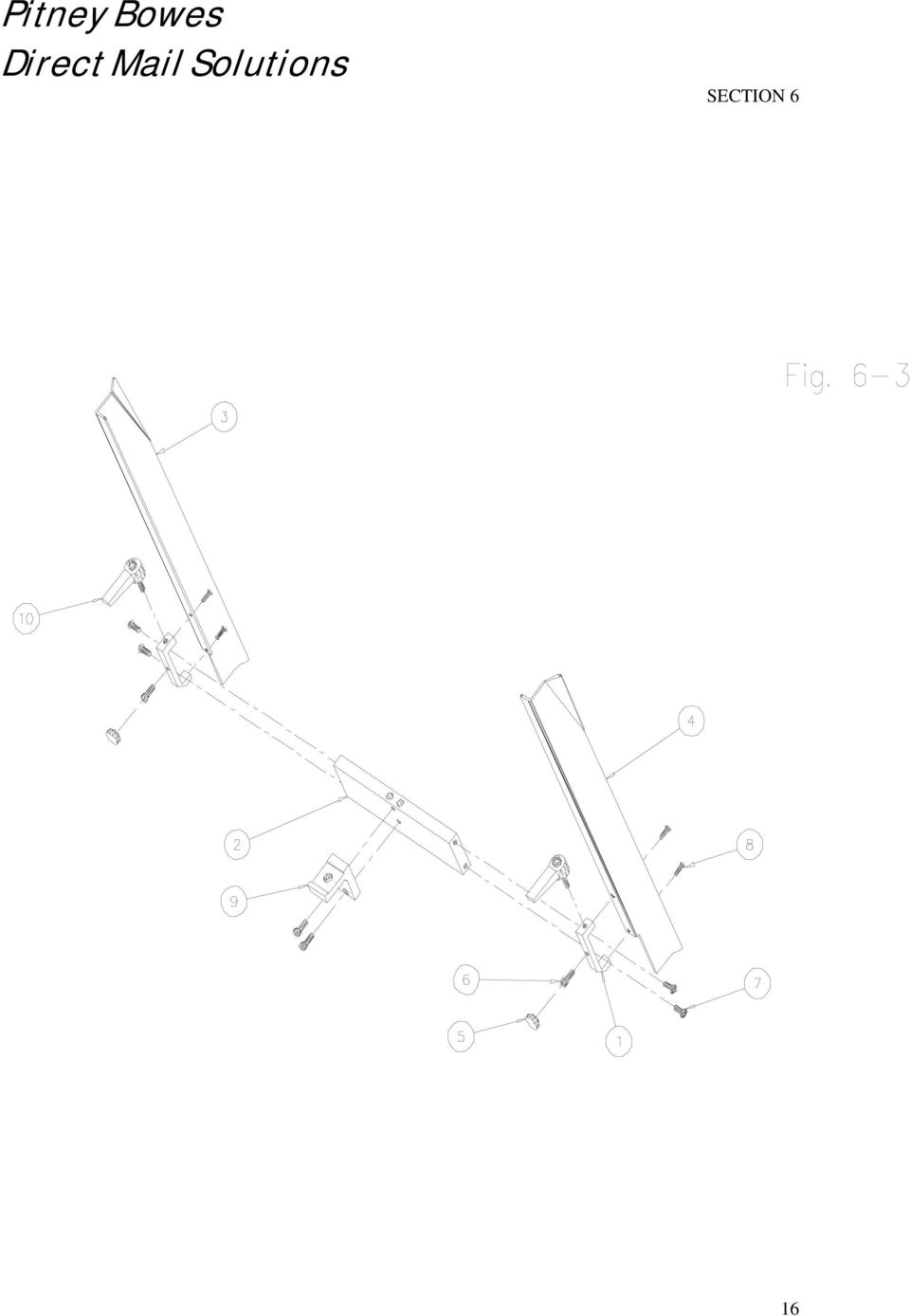
5 SECTION 2 Pitney Bowes DMS Bridge-Tramming Procedure Normally this is a factory setting that does not require adjustment. However, raising the bridge may be required to run thick material and this adjustment may be required. This setting is critical to the performance of the feeder. This will ensure that the separator wheels are level with respect to the nip rollers. To do this, first loosen the bridge mounting screws (Item 7, Fig. 6-3) on both sides of the bridge. Turn the separator adjustment CCW until the separator wheels are in their lowest position. Now place a thin strip of paper under each separator wheel (it is best to cut one piece of paper into two strips to ensure that the strips are the same thickness). Tighten one screw on each side. Move the paper strips to feel if the resistance is equal under each separator wheel. If one moves with less resistance than the other, loosen the screw on the side that is tighter and raise that side of the bridge slightly and tighten screw. Check the resistance under each separator wheel with the paper strips again and adjust accordingly. This procedure must be followed whenever the bridge is adjusted up or down for materials with different thickness. This adjustment is very critical when feeding thin materials. 4

6 SECTION 3 Pitney Bowes DMS Operation Instructions BATCH COUNTING Your Pitney Bowes DMS feeder is equipped with a batch counter. The batch value is pre-set from the factory with a value of 1. To change the batch value, first locate the batch controller on the rear of the feeder. Press the button labeled (P2) once to activate the setting mode. Now by pressing any of the buttons you can change the corresponding digit in the desired batch value. By pressing the P1 button you can change the 0 to 9 values. By pressing the P2 button you can change the 10 to 90 values. P3 changes the 100 to 900 values and so forth. As you change each digit of the value, you will see the LED display change accordingly. When you have displayed the desired batch value press the ENTER button (E) followed by the reset button (R). You are now ready to batch the desired number of pieces. (Note: You must press ENTER followed by RESET or changes will not be saved.) The new value will be stored until a different value is properly set even when the power is turned off to the feeder. Another feature associated with your batch counter is a deceleration phase at the end of the batch.. Press the button labeled (P1) once to activate the setting mode. Now by pressing the (P1) button again you can adjust the number of pieces that the feeder decelerates for. For example, if the setting is (1) the feeder slows down during the last piece in the batch. The value of 1 is normally the best setting, however if the feeder is running slow a value of (0) may work better. However, if the feeder is running fast, a deceleration value of (0) may not stop the feeder quick enough. You can extend the life of the feeder by maintaining a deceleration (P1) value of (1) or (2). 5

7 SECTION 3 Pitney Bowes DMS Operation Instructions MANUAL OPERATION There are (2) recessed buttons on the back of the feeder. The red button is the Stop / Reset button. The green button will start the feeder manually. Press the green button and the feeder will feed a batch pre-determined by the batch counter. Hold the red button down and press the green button and the feeder will feed a single piece. ERRORS There is a red LED near the manual push buttons. The feeder will stop and This LED will light up or flash if an error has occurred. The LED will flash for a missing piece, out of paper, and excessive batch time. The LED will remain lit for a paper jam. 6

8 SECTION 4 Pitney Bowes DMS Cleaning Instructions Clean rollers and belts are very important to the performance of the feeder. Use a clean rag dampened with Isopropyl Rubbing alcohol, 70% by volume (typically available in drug stores) to clean belts and rollers. Do not use any other solvents, cleaners, or abrasive cleaners on the rollers or belts as they may damage the rubber. Warning: Isopropyl rubbing alcohol is very flammable! Always unplug the machine before cleaning belts and rollers. DO NOT! use near an open flame, sparks, or any other source of ignition. DO NOT! smoke in the vicinity of the alcohol fumes. Allow used rags to air-dry before throwing them in the trash. Dispose of used rags properly. Other areas of the machine should be wiped clean with a clean dry rag. 7

9 SECTION 5 Pitney Bowes DMS Troubleshooting Guide Problem Feeder will not run. Feeder runs but no material is being dispensed. Feeder does not create a gap between pieces. Feeder does not detect material. Thick material does not feed well. Solution Check circuit breaker condition. Check outlet power source. Check power switch. Check material supply. Remove all material and follow setup procedure. Check rollers and belts for excessive wear or dirt. Lower separator adjustment and observe. If a gap is not present after this adjustment, return separator to original position and move the back guide forward. Adjust position of the sensor. Decrease the height at the back of the material stack. Increase the opening at the separation device (the thicker the material the less critical the setting is). 8

10 SECTION 5 Pitney Bowes DMS Troubleshooting Guide Cont. Problem Thin material does not feed. Material feeds double. Solution Adjust separation device as described in section 2. Remove material and fan the stack allowing air to separate the pieces. Raise the rear of the material stack by moving the wedge forward. After confirming set up is correct, inspect the o-rings. If the o-rings are worn past the shoulder of the separator wheel, they will not be effective. Replace the o-rings and reset the gap. 9

11 Pitney Bowes DMS Parts Manual 10

12 FEEDER ASSEMBLY (FIG. 6-1) ITEM PART NO. QTY. DESCRIPTION BELT, TIMING 90XL BELT, TIMING 100XL BELT, TIMING 120XL BELT, RED GUM 5 SEE FIG SEPERATOR DEVICE ASSEMBLY 6 SEE FIG SIDE GUIDE ASSEMBLY 7 SEE FIG FRONT SHAFT ASSEMBLY 8 SEE FIG SUPPORT SHAFT ASSEMBLY 9 SEE FIG SUPPORT IDLER SHAFT ASSEMBLY 10 SEE FIG MAIN SHAFT ASSEMBLY 11 SEE FIG CLUTCH SHAFT ASSEMBLY 12 SEE FIG PAPER SLIDE ASSEMBLY 13 SEE FIG MOTOR ASSEMBLY 14 SEE FIG CHASSIS ASSEMBLY 15 SEE FIG ELECTRICAL COMPONENT ASSEMBLY 16 SEE FIG TRAILING ARM ASSEMBLY 17 SEE FIG ACCELERATOR ASSEMBLY 11

13 12

14 SEPARATOR DEVICE ASSY (Fig. 6-2) ITEM PART NO. QTY. DESCRIPTION BLOCK, SEPARATOR, 3 ROLLER PLATE, MOTOR MOUNT (SEPARATOR) SHAFT, SEPARATOR SHROUD, SEPARATOR MOTOR, SEPARATOR PULLEY, 100MXL025 (NO HUB 3/8 B) PULLEY, 16MXL025 (3/16 B) WHEEL, SEPARATOR, 3 DIA BELT, 115 MXL REF BLOCK, SEPARATOR ADJ STUD, SEPARATOR ADJ BEARING, 3/8 ID X 7/8 OD, SHIELDED KNOB, FEM, 5/ O-RING, SEPARATOR, SPRING,.068 X.48 X 1 7/ PIN, DOWEL, 3/8 X 1 1/ STANDOFF, SEPARATOR MOTOR 18 1 NUT, HEX, 5/ WASHER, FLAT, 5/ SCREW, PAN HD, 6-32 X 2 1/ SCREW, SET, X 1/ SCREW, SET, X 3/ SCREW, FLAT HD, 8-32 X 1/ WASHER, NYLON, 3/8 X 1/ WASHER, NYLON, 3/8 X 1/ PIN, DOWEL, 5/16 X 3 13

15 14

16 SIDE GUIDE ASSEMBLY (Fig. 6-3) ITEM PART NO. QTY. DESCRIPTION BRACKET, SIDE GUIDE MTG CROSS BAR, SE-600-P GUIDE, SIDE, RH (TALL) GUIDE, SIDE, LH (TALL) KNOB, #10 SCREW 6 4 SCREW, SKT HD, X 1/2 7 4 SCREW, BTN HD, X 1/2 8 4 SCREW, FLAT HD, 6-32 X 1/ BLOCK, SEPARATOR ADJ HANDLE, RATCHET,

17 16
18 FRONT SHAFT ASSEMBLY (Fig. 6-4) ITEM PART NO. QTY. DESCRIPTION SHAFT, FRONT SE-600-P BEARING, 1/4" ID X 5/8" OD SEALED 17

19 18

20 SUPPORT SHAFT ASSEMBLY (Fig. 6-5) ITEM PART NO. QTY. DESCRIPTION ROLLER, NIP PULLEY, MATE SHAFT, NIP ROLLER SE-600-P PULLEY, 20XL PULLEY, 24XL BEARING, 1/2" ID X 1-1/8" OD, SHIELDED W/ S.R RETAINING RING, 1/2 8 6 SCREW, SET, X 3/8 9 4 SCREW, SET, 8-32 X 3/8 19

21 20
22 SUPPORT IDLER SHAFT ASSEMBLY (Fig. 6-6) ITEM PART NO. QTY. DESCRIPTION ROLLER, IDLER SHAFT, SUPPORT IDLER SE-600-P BEARING, 3/8 ID X 7/8 OD, SHIELDED RETAINING RING, 3/8 5 2 SCREW, BTN HD, X 1/2 21
23 22
24 MAIN SHAFT ASSEMBLY (Fig. 6-7) ITEM PART NO. QTY. DESCRIPTION FEEDER ROLLER PULLEY, CROWNED SHAFT, MAIN SE-600-P PULLEY, 20XL PULLEY, 24XL BEARING, 1/2" ID X 1-1/8" OD, SHIELDED RETAINING RING, 1/2 8 2 SCREW, SET, X 3/8 9 4 SCREW, SET, 8-32 X 3/8 23
25 24
26 CLUTCH SHAFT ASSEMBLY (Fig. 6-8) ITEM PART NO. QTY. DESCRIPTION SHAFT, CLUTCH SE-600-P CLUTCH PULLEY, CLUTCH 36XL PULLEY, 22XL BEARING, 1/2" ID X 1-1/8" OD, SHIELDED RETAINING RING, 1/2 7 2 SCREW, SET, 8-32 X 3/8 8 3 SCREW, PAN HD, 6-32 X 1/ WASHER, NYLON, 1/2 X 1/16 25
27 26
28 PAPER SLIDE ASSEMBLY (Fig. 6-9) ITEM PART NO. QTY. DESCRIPTION BRACKET, PAPER SLIDE SHAFT, PAPER SLIDE SE SLIDE, PAPER RETAINING RING, 1/ KNOB, #10 SCREW 6 1 SCREW, SKT HD, X 1/ NUT, PAPER SLIDE WASHER, PAPER SLIDE PIN, ROLL, 5/32 X 3/ WASHER, FLAT, #6 27
29 28
30 MOTOR ASSEMBLY (Fig. 6-10) ITEM PART NO. QTY. DESCRIPTION STANDOFF, MOTOR PULLEY, MOTOR 16XL MOTOR, 4Z STOP, CLUTCH PIN, ROLL, 3/16 X 1 1/4 6 4 SCREW, SET, 1/4 X 3/4 7 5 SCREW, BTN HD, X 1/2 8 2 SCREW, SET, 8-32 X 1/4 29
31 30
32 CHASSIS ASSEMBLY (Fig. 6-11) ITEM PART NO. QTY. DESCRIPTION SIDE FRAME, LH (SE-600-P) SIDE FRAME, RH (SE-600-P) COVER, TOP COVER, BOTTOM CROSS BRACE, LOWER CROSS BRACE, UPPER SUCTION CUP, FOOT 8 6 SCREW, BTN HD, X 1/2 9 8 SCREW, BTN HD, X 3/ NUT, PEM SCREW, SKT, HD, X FOOT, BOTTOM 13 1 SCREW, SKT HD, X 1/2 31
33 32
34 ELECTRICAL COMPONENT ASSEMBLY (Fig. 6-12) ITEM PART NO. QTY. DESCRIPTION SWITCH, POWER (RED ROCKER) TERMINAL STRIP CIRCUIT BOARD (IO) CIRCUIT BOARD, SWITCH CIRCUIT BOARD, BATCH COUNTER (600-PC ONLY) CONTROLLER, MOTOR, 90V DC W/ SPEED POT COUNTER, BATCH (600-PC ONLY) COUNTER, CYCLE (600-PS ONLY) RIBBON CABLE (IO BOARD) (NOT SHOWN) TRANSFORMER CIRCUIT BREAKER, 2 AMP RECEPTACLE, POWER CORD CORD, POWER (NOT SHOWN) 13 2 SCREW, PAN HD 6-32 X 3/ SCREW, PAN HD 6-32 X 1/ SCREW, FLAT HD 6-32 X 1/ NUT, HEX KNOB, SPEED POT SWITCH, ROCKER (SMALL, RED) POT KIT, TIME DELAY (PC) / AUTO RESTART (PS) SENSOR, FREE HANGING (NOT SHOWN) CABLE, SENSOR (YELLOW) (NOT SHOWN) 33
35 34
36 TRAILING ARM ASSEMBLY (fig. 6-13) ITEM PART NO. QTY. DESCRIPTION PLATE, ROLLER MTG. (TONGUE) SPACER ROLLER WEIGHT 5 2 SCREW, PAN HD, 8-32 X 1 1/4 6 2 SCREW, PAN HD, 8-32 X 3/8 7 4 WASHER, LOCK INT. TOOTH #8 35
37 36
38 ACCELERATOR ASSEMBLY (fig. 6-14) ITEM PART NO. QTY. DESCRIPTION 1 SEE FIG ACCELERATOR CHASSIS ASSEMBLY 2 SEE FIG ST ACCELERATOR SHAFT ASSEMBLY 3 SEE FIG ND ACCELERATOR SHAFT ASSEMBLY 4 SEE FIG RD ACCELERATOR SHAFT ASSEMBLY 5 SEE FIG ROLLER RACK ASSEMBLY 6 SEE FIG INTERMEDIATE DRIVE PULLEY ASSEMBLY 37
39 38
40 ACCELERATOR CHASSIS ASSEMBLY (fig. 6-15) ITEM PART NO. QTY. DESCRIPTION SIDE FRAME, LH ACCELERATOR (PC/PS) SIDE FRAME, RH ACCELERATOR (PC/PS) BAR, ROLLER RACK MTG (SE-600-P) BAR, ROLLER RACK SUPPORT SCREW, SHOULDER, 1/4X1/4 6 8 SCREW, BTN HD, X 3/8 7 8 SCREW, SKT HD, 8-32 X 1/2 39
41 40
42 1 ST ACCELERATOR SHAFT ASSEMBLY (fig. 6-16) ITEM PART NO. QTY. DESCRIPTION SHAFT, DRIVE (ACCELERATOR) SE-600-P PULLEY, CROWNED PULLEY, 14XL BELT, RED GUM BEARING, 1/2 X 1-1/ SNAP RING, 1/2 7 2 SCREW, SET, X 3/8 8 2 SCREW, SET, 8-32 X 1/16 41
43 42
44 2 ND ACCELERATOR SHAFT ASSEMBLY (fig. 6-17) ITEM PART NO. QTY. DESCRIPTION SHAFT, SUPPORT IDLER (ACCELERATOR) SE-600-P PULLEY, MATE PAPER SLIDE PLATE, CLAMP BRACKET, SENSOR MOUNTING SENSOR, RECIEVER BEARING, 1/2 X 1-1/ SNAP RING, 1/2 9 4 SCREW, BTN HD, X 3/ SCREW, BTN HD, X 1/ SCREW, BTN HD, 6-32 X 1/ SCREW, PAN HD, M3 X WASHER, FLAT, M3 43
45 44
46 3 RD ACCELERATOR SHAFT ASSEMBLY (fig. 6-18) ITEM PART NO. QTY. DESCRIPTION SHAFT, FRONT (ACCELERATOR) SE-600-P BEARING, 1/4 X 5/8 SEALED 45
47 46
48 ROLLER RACK ASSEMBLY (fig. 6-19) ITEM PART NO. QTY. DESCRIPTION BAR, ROLLER RACK SHAFT, ROLLER RACK, SHAFT, ROLLER RACK 1 1/ BEARING, 3/8 X 7/ BUSHING, 1/4 X 3/8 X 5/ PLATE, SENSOR MOUNTING SENSOR, SENDER SPRING SNAP RING 1/ KNOB, FEM, STUD, X 2 1/ SCREW, SET, 8-32 X 1/ SCREW, SKT HD, 6-32 X 1/ SCREW, PAN HD, M3 X WASHER, FLAT, M NUT, HEX, WASHER, FLAT, # GUIDE, SPRING STEEL, ROLLER RACK 19 1 NUT, HEX,
49 48
50 INTERMEDIATE DRIVE PULLEY ASSEMBLY (fig. 6-20) ITEM PART NO. QTY. DESCRIPTION SHAFT, IDLER BLOCK, IDLER SHAFT PULLEY, 20XL BELT, 80XL BELT, 90XL BEARING, 3/8 X 7/ SNAP RING, 3/8 8 1 SCREW, BTN HD, X 1/ WASHER, NYLON, 3/8 X 1/32 49
51 50
52 SECTION 7 Pitney Bowes DMS SE 600 PC & PS Electrical Schematics 51
53 600 PC 52
54 600 PS 53
55 SECTION 8 Pitney Bowes DMS SE 600 P-SERIES 2 Year Limited Warranty Pitney Bowes DMS warrants this product to be free from defects in materials and workmanship for a period of two years from the date of delivery to the customer. If at any time during this two year period, the customer feels that there is an alleged defect in the equipment, written notice must be provided to Pitney Bowes DMS who will determine a time to have the feeder inspected in the field by a representative of Pitney Bowes DMS or returned to Pitney Bowes DMS corporate headquarters. If the equipment is found to not be in conformity with this warranty, Pitney Bowes DMS will in its sole discretion expeditiously either repair the equipment or supply a replacement. Please refer to the warranty card included with this manual for additional details of this warranty. Complete the warranty card and return it to Pitney Bowes DMS as soon as possible to activate the warranty on this product. Procedure Send all warranty claims to: Pitney Bowes DMS Warranty Department th Street North Clearwater, Florida Return freight prepaid. 54
SE-1200-EI. Operation & Parts Manual
 SE-1200-EI Operation & Parts Manual SE 1200 EI OWNERS MANUAL Table of Contents 1. Installation guide 2. Set-up instructions 3. Operation instructions 4. Cleaning 5. Troubleshooting 6. Parts manual 7. Electrical
SE-900-MP ECO -SERIES. Operation & Parts Manual
 SE-900-MP ECO -SERIES Operation & Parts Manual SE 900 MP ECO - SERIES OWNERS MANUAL Table of Contents 1. Installation guide 2. Set-up instructions 3. Operation instructions 4. Cleaning 5. Troubleshooting
Section M POWER LIFTS
 Section M POWER LIFTS December 2009 1M Index 1. 53-520244-000 Poly V Idler Assembly 2. 53-520205-000 N.A. Mounting Bracket 3. 53-520212-000 Cable Assembly 4. 53-600149-000 Wire Harness Assembly 5. 53-860322-010
TERMINATION EQUIPMENT INSTRUCTION MANUAL TELE-PIERCE P/N 356-246
 TERMINATION EQUIPMENT INSTRUCTION MANUAL TELE-PIERCE P/N 356-246 OPERATION AND SERVICE INSTRUCTIONS AMPHENOL 157 SERIES TELE-PIERCE MULTI-WIRE TERMINATION TOOL 356-246 AMPHENOL TERMINATION SYSTEMS 1830
 UFO 1 FOLDER INDEX A2 FOLDING MACHINE TYPE 10060 LIST NO DESCRIPTION PAGE 10101M Main Assembly - Mechanical 2 10201M Main Roller Assembly 4 16101M Upper & Lower Perforator Shaft Assembly 6 12701M Primary
Number Wheeler P/N Description Set Rex P/N Notes
 1 604041 Base 1 4041 2 604042 Base Cover 1 4042 3 608849 Washer (M5) 2 4 600124 Spring Washer (M5) 2 5 600329 Rd Hd Machine Screw (M5x8) 2 6 604047 Strainer 1 4047 7 600204 Rd Hd Machine Screw (M6x10)
Number Wheeler P/N Description Set Rex P/N Notes
 1 607051 Base 1 A050 2 607052 Motor Cover 1 A052 3 600778 Socket Hd Cap Screw (M8x60) 2 4 607053 Scrap Receiver 1 A053 5 607054 Tank Upper Cover 1 A054 6 607055 Oil Pot 1 A055 7 607056 Strainer 1 A056
Number Wheeler P/N Description Set Rex P/N Notes 1 603500 Base 1 J001 2 603501 Support, Right 1 J002 3 603502 Support, Left 1 J003 4 600328 Nut (M8)
") 1 603500 Base 1 J001 2 603501 Support, Right 1 J002 3 603502 Support, Left 1 J003 4 600328 Nut (M8) 4 5 600130 Spring Washer (8mm) 4 6 600344 Roll Pin (M6x30) 4 7 600129 Socket Hd Cap Screw (M8x25) 4 8
1 603500 Base 1 J001 2 603501 Support, Right 1 J002 3 603502 Support, Left 1 J003 4 600328 Nut (M8) 4 5 600130 Spring Washer (8mm) 4 6 600344 Roll Pin (M6x30) 4 7 600129 Socket Hd Cap Screw (M8x25) 4 8
COMMERCIAL GAS DRYER
 COMMERCIAL GAS DRYER MODELS CGD8990XW0 4 12 Litho In U.S.A. (CMS) (psw) c 2012 WHIRLPOOL CORPORATION Part No. Rev. B TOP AND CONSOLE PARTS 2 TOP AND CONSOLE PARTS 1 Literature Parts W10184516 Installation
Auto Sentry-eXP Maintenance
 Auto Sentry-eXP Maintenance Maintenance Procedures for Auto Sentry exp Bill Dispenser Credit Card Reader Bill Acceptor Bill Dispenser Maintenance Bill Dispenser Problem / Cause Bill Dispenser Error Codes
Edge 28B. Simple. Clean. PARTS LIST KENT model: 908 4703 010 146 3087 000(1)2007-01
2007-01") PARTS LIST KENT model: 908 4703 010 Simple. Clean. 2007-01 2 2007-01 TABLE OF CONTENTS 1 DESCRIPTION PLAN GENERAL VIEW 2-3 CHASSIS SYSTEM 4-5 SIDE BROOM ASSEMBLY 6-7 HOPPER SYSTEM 8-9 TRANSMISSION SYSTEM
PARTS LIST KENT model: 908 4703 010 Simple. Clean. 2007-01 2 2007-01 TABLE OF CONTENTS 1 DESCRIPTION PLAN GENERAL VIEW 2-3 CHASSIS SYSTEM 4-5 SIDE BROOM ASSEMBLY 6-7 HOPPER SYSTEM 8-9 TRANSMISSION SYSTEM
Resharpening Companion
 Resharpening Companion 10950 Correct Angles, Pictures, and Step-By-Step Instructions The Resharpening Companion is meant to be a guide and quick reference to help you resharpen. It is not meant to replace
Pallet Jack. OWNER S MANUAL Model MH1230. Important Safety Instructions Assembly Instructions Parts and Hardware Identification
 OWNER S MANUAL Model MH1230 Important Safety Instructions Assembly Instructions Parts and Hardware Identification Pallet Jack CAUTION: Read, understand and follow ALL instructions before using this product
3000, 4000, 4100, 7500, 7700
 3000, 4000, 4100, 7500, 7700 Drum & Disc Brake Lathes s Identification READ these instructions before placing unit in service. KEEP these and other materials delivered with the unit in a binder near the
SECTION G2: CABLE PROCESSOR MODULE MAINTENANCE
 SECTION G2: CABLE PROCESSOR MODULE MAINTENANCE Cable Processor Module overview WARNING! When tipping the Cable Processor Module back, (after removing the toggle arm pin), use extreme caution not to drop
DL-9000 Ticket Eater with AP-100 Logic Board
 DL-9000 Ticket Eater with AP-100 Logic Board DL-9000 Ticket Eater by Deltronic Labs February 2013 1 Table of Contents Initial Setup... 3 Handling Messages on the Display... 3 DL Ticket Eater Manager Software...
SERVICE PARTS LIST PAGE 1 OF 6 BASE ASSEMBLY SPECIFY CATALOG NO. AND SERIAL NO. WHEN ORDERING PARTS 12" DUAL BEVEL COMPOUND MITER SAW B27A
 PAGE 1 OF 6 BASE ASSEMBLY 00 0 EXAMPLE: Component Parts (Small #) Are Included When Ordering The Assembly (Large #). SPECIFY CATALOG NO. AND NO. WHEN ORDERING PARTS 1 02-80-0050 Thrust Bearing (1) 2 05-80-0510
DOOR PARTS SECTION D-1
 DOOR PARTS SECTION D-1 1 11 10 11 9 8 1 1 7 6 10 5 4 D- DOOR ASSEMBLY ITEM NO DESCRIPTION QTY. PART NO 1 SERVICE DOOR ASSEMBLY ~ * CONTROL PANEL 1 * DOOR GUARD 1 * 4 DOOR ROLLER ASSEMBLY 1 1148-7 5 T-HANDLE
Replacement Parts Catalog
 Replacement Parts Catalog Replacement Parts Contents A-Class Right Hand 4 Model Printer Assemblies... 1 Cover Assembly (15-3021-01)... 2 Display Assembly (24-2605-01)... 3 Direct Thermal (78-2474-01)...
OPL BASIC. Dosing System for Professional Laundry machines. Contents
 OPL BASIC Dosing System for Professional Laundry machines Contents 1 Getting Started. Page 2 2 Installation. Page 4 3 Set Up & Operation. Page 8 4 Maintenance & Accessories. Page 10 5 Troubleshooting Page
ELECTRIC KNIFE SHARPENER
 PRODUCT MANUAL- M109 MODEL 401 ELECTRIC KNIFE SHARPENER Please read thoroughly before operation and keep for future reference Model 401 Knife Sharpener Specifications Model No. #401 Power Requirements
D I G I T A L C L A M
 T h e M A X X P r e s s D I G I T A L C L A M O P E R A T O R S M A N U A L 6 x0 x5 5 x5 Folie & Papper Sweden AB Box 90 00 9 Göteborg Telefon 03-9 00 80 Fax 03-9 00 89 www.foliepapper.se Safety Instructions
INSTRUCTION MANUAL AND PARTS LIST MODEL 14-10
 VERTICAL BAND SAWS INSTRUCTION MANUAL AND PARTS LIST MODEL 1-10 DAKE/PARMA WHEN ORDERING PARTS GIVE COMPLETE SERIAL NUMBER OF MACHINE GIVE PART NUMBER AND NAME GIVE AMOUNT REQUIRED Unless the above data
Fleck 4650. Service Manual INSTALLATION AND START-UP PROCEDURE TABLE OF CONTENTS JOB SPECIFICATION SHEET
 Fleck 4650 Service Manual TABLE OF CONTENTS JOB SPECIFICATION SHEET...1 INSTALLATION AND START-UP PROCEDURE...1 CONTROL VALVE DRIVE ASSEMBLY...2 CONTROL DRIVE ASSEMBLY FOR CLOCK...3 BYPASS VALVE ASSEMBLY...4
PALLET JACK - 2.5 TON
 PALLET JACK - 2.5 TON 39939 SET UP AND OPERATING INSTRUCTIONS Visit our website at: http://www.harborfreight.com Read this material before using this product. Failure to do so can result in serious injury.
UNIVERSAL 1550 PRE-MIX DISPENSER
 MODEL NO. 284974xxx 1 of 8 Control Code A ªIMI Cornelius Co., 1987-95 22 5 6 2 3 7 4 1 26 32 19 28 33 29 27 11 15 18 16 17 14 9 31 30 34 24 20 23 8 10 21 13 FIGURE 1. ASSEMBLY ªIMI Cornelius Co., 1987-95
OWNER'S MANUAL FOR MODEL "SM 12"
 OWNER'S MANUAL FOR MODEL "SM 12" USE AND CARE OF YOUR ELECTRIC FOOD SLICER General Slicing/Red Goat Disposers 1152 Park Avenue P.O. Box 428 Murfreesboro, Tennessee 37133-0428 (615)893-4820 IMPORTANT! READ
K&T Saw Shop 606-678-9623 or 606-561-4983
 13-600072-06 PRO MAC 8200 05/92 to Current IPL 215710-02 Page 1 of 20 Carburetor Assembly www.ktoutdoor.com 13-600072-06 PRO MAC 8200 05/92 to Current IPL 215710-02 Page 2 of 20 Carburetor Assembly 214763-02
PARTS BOOK. hohner 48/5S. Stitcher Head. Vol.2 UB706016-01. 110407/hohner48/5S/01/KS
 PARTS BOOK hohner /5S Stitcher Head 007/hohner/5S/0/KS Vol. UB70606-0 Hohner /5 Revision Control List Page / Correction (a: Parts No. c: Description d: S/N e: Remarks f: Other g: Registration h: Illustration
DR90. Baja Motorsports Inc. P.O. Box 61150 Phoenix, AZ 85082 Toll Free: 888-863-2252 PART NUMBERS AND PRICES ARE SUBJECT TO CHANGE 1 of 51
 DR90 Toll Free: 888-863-2252 PART NUMBERS AND PRICES ARE SUBJECT TO CHANGE 1 of 51 CYLINDER & CYLINDER HEAD 1 DR90-001 842645048166 CYLINDER 1 1 2 DR90-002 842645048173 GASKET, CYLINDER 1 1 3 DR90-003
PRODUCT MANUAL - M090
 PRODUCT MANUAL - M090 MODEL 203/266 ELECTRIC CAN OPENER 1 SAFETY CAUTION: SEVERED CAN LIDS HAVE CUTTING EDGES. USE OF A PROTECTIVE GLOVE OR TONGS IS ADVISED WHEN HANDLING LIDS. WARNING To avoid risk of
11-600036D PRO MAC 60 07/72 to 12/76 IPL 89321 Page 1 of 19 Accessories
 11-600036D PRO MAC 60 07/72 to 12/76 IPL 89321 Page 1 of 19 Accessories 11-600036D PRO MAC 60 07/72 to 12/76 IPL 89321 Page 2 of 19 Accessories 84453 Kit - Piston tool 69191 Kit - Pressure test adaptor
2510/2550 Dust Control Burnisher
 250/2550 Dust Control Burnisher Operator and Parts Manual TENNANT COMPANY Commercial Products 2875 RANSOM STREET HOLLAND MI 49424 U.S.A. FAX: 800 678 4240 CUSTOMER SERVICE: 800-982 7658 607597 Rev. 0 (2-00)
MODEL 4065T-PM-CART POWERED MANUAL STRETCH WRAP SYSTEM OPERATOR S MANUAL
 MODEL 4065T-PM-CART POWERED MANUAL STRETCH WRAP SYSTEM OPERATOR S MANUAL 1 Table of Contents Introduction 3 Warranty 3 Modular Design 3 Assembly 4 Set-up 4 Film loading Constant Prestretch 4 Controls 5
Neptune. replace. Owners Manual
 Neptune replace Owners Manual Training with the Neptune Rower 1. As with any piece of fitness equipment, consult a physician before beginning your Neptune Rower exercise program. 2. Follow instructions
You're reading an excerpt. Click here to read official BH FITNESS T1 BASIC user guide http://yourpdfguides.com/dref/2696507
 You can read the recommendations in the user guide, the technical guide or the installation guide for BH FITNESS T1 BASIC. You'll find the answers to all your questions on the BH FITNESS T1 BASIC in the
Char-Lynn Hydraulic Motor. Repair Information. 10 000 Series. October, 1997
 Char-Lynn Hydraulic Motor October, 1997 Repair Information Geroler Motor Two Speed 001 27 Retainer inside bore of valve plate bearingless motors only 4 15 16 3 6 35 Parts Drawing 25 2 2 1 19 17 36 40 47
DR50 Hensim Dirt Runner 49cc Dirt Bike (VIN PREFIX LLCH or LUAH)
") Page 1 of 21 Product Information Baja Web > Product Information > Parts Lists > DIRTBIKE > DR50 Hensim Dirt Runner 49cc Dirt Bike (VIN PREFIX LLCH or LUAH) DR50 Hensim Dirt Runner 49cc Dirt Bike (VIN PREFIX
Page 1 of 21 Product Information Baja Web > Product Information > Parts Lists > DIRTBIKE > DR50 Hensim Dirt Runner 49cc Dirt Bike (VIN PREFIX LLCH or LUAH) DR50 Hensim Dirt Runner 49cc Dirt Bike (VIN PREFIX
LU6X-130 Instructions and Parts List (including LU6X Basic) Operating Instructions
 Operating Instructions") LORTONE LU6X-130 Item # 061-092 LU6X Basic Item # 061-090 LU6X-130 Instructions and Parts List (including LU6X Basic) Operating Instructions Introduction The LU6X is one the most versatile pieces of equipment
LORTONE LU6X-130 Item # 061-092 LU6X Basic Item # 061-090 LU6X-130 Instructions and Parts List (including LU6X Basic) Operating Instructions Introduction The LU6X is one the most versatile pieces of equipment
1/29/2008 DR50. Baja Motorsports Inc. P.O. Box 61150 Phoenix, AZ 85082 Toll Free: 888-863-2252 PART NUMBERS PRICES ARE SUBJECT TO CHANGE 1 of 45
 DR50 Toll Free: 888-863-2252 PART NUMBERS PRICES ARE SUBJECT TO CHANGE 1 of 45 CYLINDER & CYLINDER HEAD Part UPC Number Description Baja Description 1 DR50-001 842645074424 CYLINDER 1 1 2 DR50-002 842645074431
User Manual. Instructions for installing the Sure Stitch on the Next Generation Quilting Frame. Parts Included:
 User Manual Instructions for installing the Sure Stitch on the Next Generation Quilting Frame. Parts Included: 1: Display Console 1: Control Box 2: Encoder (Wires attached) (Not Shown) 1: 5v Power Supply
JANUS INTERNATIONAL CORPORATION INSTALLATION INSTRUCTIONS Pantheon Mini Operator
 JANUS INTERNATIONAL CORPORATION INSTALLATION INSTRUCTIONS Pantheon Mini Operator The Janus Pantheon mini operator does not typically require the provision of any additional site requirements other than
1/29/2008 DR125 / DR150. Baja Motorsports Inc. P.O. Box 61150 Phoenix, AZ 85082 Toll Free: 888-863-2252 PARTS AND PRICES ARE SUBJECT TO CHANGE 1 of 55
 DR125 / DR150 Toll Free: 888-863-2252 PARTS AND PRICES ARE SUBJECT TO CHANGE 1 of 55 CYLINDER HEAD ASSY. 1 125-001 883099006937 CYLINDER HEAD COVER 1 1 2 125-002 883099006944 BOLT M6X28 2 3 3 125-003 883099006951
Contents. Description Page Description Page
 Contents Description Page Description Page Auger Housing Assembly 1 Muffler 18 Handle and Control Assembly 3 Fuel Tank r Assembly 19 Engine and Drive Assembly 5 Clutch Retarder 20 Cylinder Head 7 Retarder
SECTION VII PARTS BREAKDOWN
 SECTION VII PARTS BREAKDOWN 21 REAR TINE TILLER MAIN ASSEMBLY ITEM # PART # QTY DESCRIPTION 1 SEE PAGE 25 1 ENGINE-RIGHT ANGLE DRIVE-PULLEY ASSEMBLY 2 SEE PAGE 27 1 FRAME-TRANSMISSION-HOUSING ASSEMBLY
TABLE OF CONTENTS. I. TROUBLESHOOTING... 2 - Section 1.01: Common Problems/Solutions... 2
 BAL Accu-Slide System I. Table of Contents TABLE OF CONTENTS I. TROUBLESHOOTING... 2 - Section 1.01: Common Problems/Solutions... 2 II. GETTING STARTED... 5 - Section 2.01: Tools You Will Need... 5 - Section
K&T Saw Shop 606-678-9623 or 606-561-4983. 12-400165 MC 91C 11/74 to 04/76 IPL 84456 Page 1 of 11 Accessories
 12-400165 MC 91C 11/74 to 04/76 IPL 84456 Page 1 of 11 Accessories 12-400165 MC 91C 11/74 to 04/76 IPL 84456 Page 2 of 11 Accessories 68899 Piston Assy - 0.005 in. oversize 66790 Ring Set - Piston 0.005
READ CAREFULLY - FAILURE TO FOLLOW INSTRUCTIONS AND SAFETY RULES MAY RESULT IN SERIOUS INJURY
 Owner s Manual LSP16H LS3001 LS3002H LS3003 LSP21H LS3101 LS3102H LS3103 LSP24H LS3201 LS3102H LS3103 LSP28H LS3301 LS3302H LS3303 mainframe bundle H-unit bundle accessory box mainframe bundle H-unit bundle
REEL LAWN MOWERS MASPORT 400-500-660
 Issue A June 2009 REF # 719046 REEL LAWN MOWERS MASPORT 400-500-660 Part number Model Engine MASPORT 019036 400 RRR B & S Series 475 MASPORT 019044 400 RRR Honda GX160 MASPORT 019046 500 RRR B & S Series
K&T Saw Shop 606-678-9623 or 606-561-4983
 12-600072F PRO MAC 850 SUPER CHAIN SAW 05/92 to Current IPL 215710-R1 Page 1 of 16 Accessories www.ktoutdoor.com 12-600072F PRO MAC 850 SUPER CHAIN SAW 05/92 to Current IPL 215710-R1 Page 2 of 16 Accessories
Micro Cart User's Guide
 Micro Cart User's Guide To take full advantage of the ergonomic features of your new Sun Mountain Micro Cart, please read the following information. SUN MOUNTAIN 1 Your Micro Cart has several innovative
ATS Overhead Table Shelf System INSTRUCTION MANUAL
 ATS Overhead Table Shelf System INSTRUCTION MANUAL ATS Overhead Table Shelf System Instruction Manual Warranty Newport Corporation warrants this product to be free of defects in material and workmanship
ROTOR LOADER OWNER S MANUAL
 ROTOR LOADER OWNER S MANUAL ROTOR LOADER OWNER S MANUAL WARNING IMPORTANT SAFETY INSTRUCTIONS AND GUIDELINES. Misuse of paintball equipment may cause serious injury or death. QUICK SET-UP GUIDE BATTERY
FLOORTEC R 680 B. Part List US-English. Model: FLOORTEC R 680 B
 Model: Part List US-English Table of Contents General view 3 Rotomolded assembly 5 Chassis assembly 7 Drive assembly 9 Steering assembly 11 Control pedals assembly 13 Waste container assembly 15 Filter
Parts List. For printer models: www.satoamerica.com. CL408e / CL412e PN: 9001077(D)
") Parts List For printer models: CL408e / CL412e www.satoamerica.com PN: 9001077(D) SATO America, Inc. 10350A Nations Ford Road Charlotte, NC 28273 Main Phone: (704) 644-1650 Technical Support: (704) 644-1660
Parts List For printer models: CL408e / CL412e www.satoamerica.com PN: 9001077(D) SATO America, Inc. 10350A Nations Ford Road Charlotte, NC 28273 Main Phone: (704) 644-1650 Technical Support: (704) 644-1660
ASSEMBLY DIAGRAM AND ASSEMBLY REFERENCE ULTIMA OLD SCHOOL 2 EVO & TC BELT DRIVE UNITS
 ASSEMBLY DIAGRAM AND ASSEMBLY REFERENCE ULTIMA OLD SCHOOL 2 EVO & TC BELT DRIVE UNITS BELT DRIVE ASSEMBLIES Part# 58-850 2 Old School Belt Drive Assembly - Polished Part# 58-851 2 Old School Belt Drive
DRIVE AND DRIVEN PULLEY
 11 DRIVE AND DRIVEN PULLEY SCHEMATIC DRAWING ------------------------------------------------- 11-1 SERVICE INFORMATION------------------------------------------------ 11-2 TROUBLESHOOTING-----------------------------------------------------
BR150 Pmi Baja Reaction 150cc Go Kart (VIN PREFIX L4VM)
") Page 1 of 21 Product Information Baja Web > Product Information > Parts Lists > GOKART > BR150 Pmi Baja Reaction 150cc Go Kart (VIN PREFIX L4VM) BR150 Pmi Baja Reaction 150cc Go Kart (VIN PREFIX L4VM)
Page 1 of 21 Product Information Baja Web > Product Information > Parts Lists > GOKART > BR150 Pmi Baja Reaction 150cc Go Kart (VIN PREFIX L4VM) BR150 Pmi Baja Reaction 150cc Go Kart (VIN PREFIX L4VM)
7.1. Part Lists. Hardware Insertion Machine. Instructions. Instructions
 Instructions Instructions The Parts in this section of the manual are listed by Item Number, Part Number, Description and Quantity. The Item Numbers are in a circle with an arrow pointing to the specific
DR125 and DR150 Hensim Dirt Runner 125cc and 150cc Dirt Bike (VIN PREFIX LLCH or LUAH)
") Parts Lists - DR125 and DR150 Hensim Dirt Runner 125cc and 150cc Dirt Bike (VIN PR... Page 1 of 25 Product Information Baja Web > Product Information > Parts Lists > DIRTBIKE > DR125 and DR150 Hensim Dirt
Parts Lists - DR125 and DR150 Hensim Dirt Runner 125cc and 150cc Dirt Bike (VIN PR... Page 1 of 25 Product Information Baja Web > Product Information > Parts Lists > DIRTBIKE > DR125 and DR150 Hensim Dirt
K&T Saw Shop 606-678-9623 or 606-561-4983
 11-600072-02 PROMAC 800 CHAIN SAW 08/80 to 05/85 IPL 215724-01 Page 1 of 20 Accessories & Tools www.ktoutdoor.com 11-600072-02 PROMAC 800 CHAIN SAW 08/80 to 05/85 IPL 215724-01 Page 2 of 20 Accessories
4 in 1 Strength Station
 Revision 0 September 2010 4 in 1 Strength Station Owner s Manual Record Serial Number Here Platinum by Tunturi www.tunturi.com Date www.tunturi.com of Purchase 4 in 1 Strength Station Owner s Manual Instructions
C O N T E N T S 1 ABOUT THIS PARTS LIST... 2 ENGINE GROUP... 3 3 CONTENTS-FRAME GROUP
 C O N T E N T S 1 ABOUT THIS PARTS LIST... 2 2 CONTENTS-ENGINE ENGINE GROUP ENGINE GROUP... 3 3 CONTENTS-FRAME GROUP FRAME GROUP... 5 4 ENGINE PARTS LIST... 9 5 FRAME PARTS LIST...37 1 ABOUT THIS PARTS
WARNING CANADIAN D.O.C. WARNING
 Each product and program carries a respective written warranty, the only warranty on which the customer can rely. Avery Dennison Corp. reserves the right to make changes in the product, the programs, and
IMPORTANT SAFETY RULES TO FOLLOW
 WARNING FLOOR & CARPET CLEANER Any piece of equipment can be dangerous if not operated properly. YOU are responsible for the safe operation of this equipment. The operator must carefully read and follow
K-39/K-39B. Drain Cleaning Machine. Ridge Tool Company/Elyria, Ohio, U.S.A.
 K-/K-B A- AUTOFEED Cable Chuck Pan Head Screw # - () Chuck Adapter Nose Piece Spiral Ring () Hand Grip Sleeve Clamp Springs () Spacer Clips () Gasket Drum Front Drum Liner Screw # - x () Drum Back Power
OPERATION MANUAL & PARTS LISTS
 TWA 1000-M Manual Water Activated Taper OPERATION MANUAL & PARTS LISTS TWA 1000-M (U9701) 1 UDM 9701 TABLE OF CONTENTS Section 1 Table Of Contents-------------------------------------------- 2 Section
TC 170 & TC 170 PD TRANSFER CASE
 Automotive Corporation TC 170 & TC 170 PD TRANSFER CASE PARTS MANUAL Fabco Automotive Corporation, Livermore, CA Ph:(925) 454-9500 Fax:(925) 454-9501 1-(800) 967-8838 www.fabcoautomotive.com VII. PARTS
Exakta 6x6 No. 602246
 Page 1/7 Repair of Exakta 6x6, 2 1/4, Single Lens Reflex Exakta 6x6 No. 602246 Access to Film ounter & Winding Mechanism For convenience remove the lens. The lens release is on the left side of the camera
DR90. Baja Motorsports Inc. P.O. Box 61150 Phoenix, AZ 85082 Toll Free: 888-863-2252 PART NUMBERS AND PRICES ARE SUBJECT TO CHANGE 1 of 51
 DR90 Toll Free: 888-863-2252 PART NUMBERS AND PRICES ARE SUBJECT TO CHANGE 1 of 51 CYLINDER & CYLINDER HEAD Part UPC Number Description Baja Description 1 DR90-001 842645048166 CYLINDER 1 1 2 DR90-002
OVEN PARTS For Models:GSC308PJB05, GSC308PJQ05, GSC308PJT05, GSC308PJS05 (Black) (White) (Biscuit) (Black Stainless)
 (White) (Biscuit) (Black Stainless)") OVEN PARTS 30" BUILT IN ELECTRIC COMBO SENSOR/SC (GOLD LINE) 3 05 Litho In U.S.A. (cre) 1 Part No. Rev.A OVEN PARTS 1 Literature Parts 4455994 Installation Instructions Use & Care Guide 8300346 Microwave
OVEN PARTS 30" BUILT IN ELECTRIC COMBO SENSOR/SC (GOLD LINE) 3 05 Litho In U.S.A. (cre) 1 Part No. Rev.A OVEN PARTS 1 Literature Parts 4455994 Installation Instructions Use & Care Guide 8300346 Microwave
PARTS DIAGRAMS AND LISTS
 -PRINT- - TABLE OF CONTENTS- IV. PARTS DIAGRAMS AND LISTS T his chapter contains parts diagrams and lists for the VMI UNI-lite DOT Private Use Wheelchair Lift. The exploded view of each major lift assembly
POWER WAVE 455M/STT & (CE)
") Illustration of Sub Assemblies Illustration of Sub Assemblies Illustration of Sub Assemblies Illustration of Sub Assemblies P-450 P-450 PARTS LIST FOR POWER WAVE 455M/STT & (CE) P-450-A P-450-A ILLUSTRATION
Illustration of Sub Assemblies Illustration of Sub Assemblies Illustration of Sub Assemblies Illustration of Sub Assemblies P-450 P-450 PARTS LIST FOR POWER WAVE 455M/STT & (CE) P-450-A P-450-A ILLUSTRATION
INSTALLATION INSTRUCTIONS
 INSTALLATION INSTRUCTIONS PARTS REQUIRED Single QuickStand Parts A (1) QuickStand Unit B (1) Base Plate C (1) Platform D (1) Palm Support E (1) VESA Plate F (6) M8 x 18 mm Flat Head Machine Screws G (4)
COMMERCIAL GAS DRYER
 COMMERCIAL GAS DRYER MODELS CGM2941TQ0 CGM2941TQ1 07 08 Litho in U.S.A. (LT)(mek) c 2008 WHIRLPOOL CORPORATION Part No. Rev. B BULKHEAD PARTS (White) (White) 2 BULKHEAD PARTS 1 Literature Parts 8563800
46431x92A Garden Tractor (1998) Page 1 of 16 Body Chassis
 Page 1 of 16 Body Chassis") 46431x92A Garden Tractor (1998) Page 1 of 16 Body Chassis 46431x92A Garden Tractor (1998) Page 2 of 16 Body Chassis 1 092546E701 Bracket, Seat 2 091963 Z Plate Assembly, Switch 3 164X26 Spring, Compression
46431x92A Garden Tractor (1998) Page 1 of 16 Body Chassis 46431x92A Garden Tractor (1998) Page 2 of 16 Body Chassis 1 092546E701 Bracket, Seat 2 091963 Z Plate Assembly, Switch 3 164X26 Spring, Compression
USED BUT NOT SHOWN: ITEMS 11-24.
 FO000900 - TABBING SYSTEM, MCS TABBER 2" Item Part Number Description Quantity 1 SM022604 Base Sub Assembly, MCS Tabber (2") 1 2 AF000512 Tabbing Head, MCS 2" 1 3 VC014001 Cable, Molded, DB25M-DB25F, 3
2006 JUDY SERVICE GUIDE
 2006 JUDY SERVICE GUIDE For exploded diagram and part number information, refer to the Spare Parts Catalog available on our website at www.rockshox.com. Information contained in this publication is subject
http://waterheatertimer.org/troubleshoot-rheem-tankless-water-heater.html
 http://waterheatertimer.org/troubleshoot-rheem-tankless-water-heater.html TECHNICAL SERVICE DEPARTMENT Removal, Cleaning, & Reinstallation of the Burner Assembly For models 74 & GT199 Required tools -
Illustrated Parts List
 Spicer Tandem Axles Illustrated Parts List AXIP0085a January 1994 Single Reduction, Dual Range, & Double Reduction Addendum 461, 462, 463, 521, 581 46,000-65,000 lbs Introduction Single Reduction w/wheel
Multi-Pitch Pitching Machine USER MANUAL
 Multi-Pitch Pitching Machine USER MANUAL TABLE OF CONTENTS Thank you for purchasing the Cimarron Multi-Pitch Pitching Machine. The Cimarron Multi-Pitch Pitching Machine is a high performance pitching machine
Express5800/120Ed. Rack Mount Kit Installation Procedures PN: 455-01607-001
 Express5800/120Ed Rack Mount Kit Installation Procedures PN: 455-01607-001 Proprietary Notice and Liability Disclaimer The information disclosed in this document, including all designs and related materials,
Read This Before Operating The BaseHit
 Read This Before Operating The BaseHit IMPORTANT OPERATING INSTRUCTIONS THE ACCURACY OF THE BASEHIT PITCHING MACHINE DEPENDS ON THE QUALITY, HARDNESS AND TYPE OF BALLS USED WITH THIS PRODUCT! TREND SPORTS
CLASS III TRUCK PARTS Baker
 CLASS III TRUCK PARTS Baker Identify replacement parts for Baker PAL, PAL-AR, PAL-WR 7.2 Instant Access to 250,000 Parts and Growing Baker PAL, PAL-AR, PAL-WR 1 000 774-1033 Toggle 26 000 757-1050 Tie
S B 3 X SERVICE MANUAL. The Taste of Paradise
 S B 3 X SERVICE MANUAL The Taste of Paradise SERVICE MANUAL PAGE SECTION I GENERAL INFORMATION... 2 II GENERAL REPAIRS... 13 III PARTS... 32 IV TROUBLESHOOTING... 41 V DAILY CLEANING PROCEDURES... 43
CUSTOM AUXILIARY FORWARD LIGHTING KIT
 -J0 REV. 0--0 CUSTOM AUXILIARY FORWARD LIGHTING KIT GENERAL Kit Number -0, 0000 Models This Custom Auxiliary Lighting Kit adds lamps and turn signals to 00 and later FLHX model motorcycles. Additional
MODEL 9000. Service Manual. IMPORTANT: Fill in pertinent information on page 2 for future reference.
 MODEL 9000 Service Manual IMPORTANT: Fill in pertinent information on page for future reference. Job Specification Sheet * JOB NO. * MODEL NO. * WATER TEST * CAPACITY PER UNIT MAX. PER REGENERATION * MINERAL
I BEAM TRACK INSTALLATION
 PDQ 0/700 FESTOON SYSTEM INSTALLATION AND MAINTENANCE INSTRUCTIONS INTRODUCTION The PDQ Festoon System was designed to run on one of three sizes of I-beams: S x., S8 x 8. and S x.. System trolleys must
CHAPTER 7 PARTS LISTS, SCHEMATIC DIAGRAMS AND WARRANTY
 CHAPTER 7 PARTS LISTS, SCHEMATIC DIAGRAMS AND WARRANTY Parts List - Handlebar Assembly NOTE: Part numbers listed are available through MacKissic, Inc. Please add 916- prefix to the part number when ordering.
TOOL SCHEMATIC AND PARTS MODEL 3150/38 W16R STAPLER
 P MODEL 3150/38 W16R STAPLER IMPORTANT! DO NOT DESTROY Always refer to safety and maintenance manual #403606 for detailed information on this tool. It is the customer's responsibility to have all operators
COMMERCIAL GAS DRYER
 COMMERCIAL GAS DRYER MODELS CGM2751TQ0 (WHITE) CGM2751TQ1 (WHITE) 5 12 Litho in U.S.A. (CMS) (psw) c 2012 WHIRLPOOL CORPORATION Part No. W10119631 Rev. C TOP AND CONSOLE PARTS W10119631 2 TOP AND CONSOLE
OVEN PARTS For Models:GMC305PDB07, GMC305PDQ07, GMC305PDT07, GMC305PDS07 (Black) (White) (Biscuit) (S.Steel)
 (White) (Biscuit) (S.Steel)") OVEN PARTS 30" BUILT IN ELECTRIC COMBO SENSOR/SC (GOLD LINE) 7 03 Litho In U.S.A. (cre) 1 Part No. OVEN PARTS NOTE: The screws and nuts required to attach a part are listed immediately following that part.
OVEN PARTS 30" BUILT IN ELECTRIC COMBO SENSOR/SC (GOLD LINE) 7 03 Litho In U.S.A. (cre) 1 Part No. OVEN PARTS NOTE: The screws and nuts required to attach a part are listed immediately following that part.
CETAC Z-Drive Assembly
 CETAC Z-Drive Assembly Replacement Guide Manual Part Number 610144 Rev 1, 2012 CETAC Technologies, Printed in USA Overview This guide describes the necessary steps to replace the Z-drive assembly on your
For exploded diagram and part number information, refer to the Spare Parts Catalog available on our website at www.rockshox.com.
 For exploded diagram and part number information, refer to the Spare Parts Catalog available on our website at www.rockshox.com. Information contained in this publication is subject to change at anytime
YARD CRUISER HYDRO DRIVE SERIES 1 & 2
 Parts Manual for YARD CRUISER HYDRO DRIVE SERIES 1 & MODELS YZ11BE YZ181BE YZ15BVE YZ158BVE TM CONTENTS DESCRIPTION PAGE(S) DESCRIPTION PAGE(S) WHEELS- REAR... CASTER, FRONT WHEEL & TIRE ASSM Y.... FRONT
MODEL T200-F18 MODEL T125-F18 Finish Nailers
 P MODEL T200-F18 MODEL T125-F18 Finish Nailers IMPORTANT! DO NOT DESTROY It is the customer s responsibility to have all operators and service personnel read and understand this manual. OPERATING MANUAL
12-Volt Negative Ground Installation Instructions
 12-Volt Negative Ground Installation Instructions For Part Number: 1141, 1164, 1165, 1181 CAUTION!!! Before installing, please read the following important information... 1. The Ignitor is designed for
Speed-Mat Rectangle Cutter
 Speed-Mat Rectangle Cutter 1 Honeycomb baseboard. 2 Left hold down. 14 3 Bottom hold down. 4 4 Left / right rule. 8 5 8 5 Left / right rule pointer. 1 6 Top / bottom rule. 7 Top / bottom rule pointer.
For exploded diagram and part number information, refer to the Spare Parts Catalog available on our website at www.rockshox.com.
 For exploded diagram and part number information, refer to the Spare Parts Catalog available on our website at www.rockshox.com. 2 0 0 5 D U K E A I R X C / S L / R A C E S E R V I C E G U I D E Information
1-800-295-5510 uline.com SPECIFICATIONS
 H-1394, H-1395, H-1396 H-1397, H-3859, H-3860 π GRAVITY CONVEYOR 1-800-295-5510 uline.com SPECIFICATIONS Conveyor Bed Width In (mm) 18, 24, 30 (457, 610, 762) Load Capacity Per Linear Foot (305mm) Lbs