Kerosene-Fired Water Heater. Operation and Maintenance Instructions
|
|
|
- Ross Quentin Boyd
- 8 years ago
- Views:
Transcription
1 Kerosene-Fired Water Heater Operation and Maintenance Instructions MODEL FB-38N(FS)/FB-52N(FS) IMPORTANT READ AND UNDERSTAND INSTRUCTIONS BEFORE INSTALLING OR USING THIS WATER HEATER. RETAIN INSTRUCTIONS FOR FUTURE REFERENCE. CHECK LOCAL CODES AND ORDINANCES FOR PERMITTED USE. CAUTION THIS WATER HEATER SHALL NOT BE USED FOR COMMERCIAL USE OR ANY PURPOSES OTHER THAN HOT WATER SUPPLY USES. OTHER USAGE MAY CAUSE A MALFUNCTION OR SHORTEN ITS SERVICE LIFE. DO NOT REMOVE THE RATING PLATE AND LABELS FROM THE WATER HEATER UNIT. [CONTENTS] SECTION A: Inspection before Operation Safety Tips...2 Operation Safety Features...4 Turning Unit Off Adjusting Water Temperature SECTION B: Differential Switch and Dip Switch Specifications...5 Preventing Freeze Up Dimensional Outline...6 Long Term Inactivity Remote Control...7 Construction...8 SECTION E: Routine Maintenance SECTION C: Inspection and Maintenance Fuel Guide Inspection and Maintenance Items SECTION D: SECTION F: Operation Troubleshooting Fueling Error Code in Display Removing Air Trap Wiring Diagram

2 SECTION A: SAFETY TIPS BE SURE TO FOLLOW THE FOLLOWING INSTRUCTIONS. The instructions which are contained in this manual are classified into the following two types, which are WARNING and CAUTION. These instructions are intended to provide the important information for safe operation. WARNING indicates the possibility of causing the user a fatal accident or serious injury if the water heater is incorrectly operated. CAUTION indicates the possibility of causing the user injuries or material damages if the water heater is incorrectly operated. WARNING 1. Never use any fuel other than water-clear kerosene. NEVER USE GASOLINE! Use of such fuels can result in an explosion and/or fire and cause injury. 2. Never store flammable liquids or materials such as gasoline near the unit. 3. This unit should be installed by a licensed, authorized person(s) due to the necessity of making electrical, water and fuel connections. 4. RISK OF BACKFIRE AND INDOOR AIR POLLUTION. Before operation make sure exhaust pipe is free of snow, icing, leaves, bird s nest or strong drafts. 5. RISK OF INDOOR AIR POLLUTION AND FIRE. Be sure the exhaust pipe is properly installed and connected. Aluminum tape may be used for sealing exhaust pipe connections. 6. RISK OF INJURY FROM MOVING PARTS AND ELECTRICAL SHOCK. Disconnect power cord before servicing unit. 7. This water heater is designed to be used no more than 1,300 m above sea level. The water heater may have a failure of combustion at a high altitude. Ask your local dealer for using at altitudes higher 800 m ~ 1,300 m above sea level. CAUTION 1. Do not use the water heater without circulating water in the heat exchanger. Routinely make sure if the circulation water has decreased. 2. Do not touch hot areas, the exhaust pipe or the exhaust pipe top. 3. Never place any combustibles on or around your water heater. 4. Never place or use any flammable dangerous substances, such as gasoline and thinner, on or around your water heater. Also never use your water heater in a location where flammable gas is generated. 5. Do not use the water heater in the event of failure or breakage. A faulty repair or modification can be dangerous. 6. Do not damage, bundle, strain, or place heavy objects on the power cord. Never yank the cord to unplug it. 2

3 7. Insert the plug securely into the outlet as far as it will go. Do not use a damaged plug or loosened outlet. Do not remove or insert the plug with wet hands. 8. When you may not use it for a long period of time, turn off the operation switch, securely close the fuel feed valve of the fuel tank, and then remove the power cord plug from the outlet. When restarting the water heater, first check to be sure that circulating water is provided. Then, insert the power cord plug into the outlet, open the fuel feed valve of the fuel tank and turn on the power switch. 9. Remove the plug from the outlet and remove dust (and metal) from the plug. Accumulation of dust may cause defective insulation due to moisture, which could pose a fire hazard. OTHER PRECAUTIONS 1. If the water heater is installed outside, the exhaust pipe top (optional parts) must be used. 2. If the unit appears to be operating abnormally or in an emergency, turn off the unit and call an authorized service person. 3. The circulating water should contain proper quantity of antifreeze solution. Avoid the use of hard water. In regions where hard water is the only source, take advantage of a water softener. 4. Do not use a damaged unit. If repairs are needed, contact your dealer. 5. Keep the area around the unit, the fuel tank and the exhaust pipe clean and free of flammable materials. 6. If you plan to be away from your home for a long period of time, shut-off the fuel valve on the fuel tank. Press operation switch to OFF position and disconnect the power supply cord. 7. If the unit is not used for a long period of time, the fuel tank may contain water cause by condensation. Be sure to check all filters and fuel strainers for this condiners for this condition, clean or replace filter elements before using the unit.. 8. Make sure that there are no leakage in fuel pipe and water circulation pipe. 9. Use the power source AC230, 50Hz only. 10. The unit must be installed at a place where there is enough air for combustion. 11. Plug on the power supply cord is disconnective device. The socket-outlet shall be installed near the water heater and shall be easily accessible. 3
 from the plug.")
4 SAFETY FEATURES NOTE: When a safety device is activated, the water heater is automatically extinguished. At this time, the error code is indicated on the digital display. When your water heater does not operate properly after you take remedies for the error correction, contact your dealer. 1. Ignition Safety Device (Flame Sensor) The unit will automatically stop all operations if ignition fails or if the flame fails during combustion. E and 6 or E and 7 will flash in the display alternately. 2. Over Heat Protector In order to prevent burns, the over heat protector automatically stops all operations if the water in the heat exchanger reaches abnormally high temperatures due to temperature controller malfunction. E and 4 will flash alternately 3. Power Failure Recovery System If power fails during water heater operation the unit will turn off. When power resumes the unit will automatically reignite. 4. Tip-over Switch When the unit senses an earthquake or shock, this device activates to stop the operation. E and 5 will flash alternately. 5. Fuel Strainer Special strainer catches any dirt or impurities present in the fuel before it is sent to the burner. 6. Heat Exchanger Bi-Metal Switch If the heat exchanger temperature is raised abnormally because of a malfunctioning thermostat, the burner is automatically extinguished and E and 9 will flash alternately. Press the POWER SWITCH again after pressing the Reset button of the Heat exchange bi-metal switch. CAUTION: Disconnect the power cord before servicing unit. RISK OF BURN INJURY. Do not touch the heat exchanger while in hot. 7. Thermal Fuse If the inside temperature of the water heater is raised abnormally, the unit is automatically extinguished and E and 9 will flash alternately. If this safety device is activated, disconnect the power cord and contact your dealer. 4

5 SECTION B: SPECIFICATIONS SPECIFICATIONS Model: FB-38N(FS) / FB-52N(FS) Type: - Combustion Type Pressure Vapor - Exhaust system Forced Exhaust type - Purpose Floor Heating Ignition: Fuel: Fuel Consumption: High Voltage Discharge Spark Kerosene (Paraffin) 4.2 L/h / 5.85 L/h Efficiency: 87.0% Heating Output: Capacity of Heat Exchanger: Max. Pressure: 128,300 BTU/h / 179,000 BTU/h (37.6 kw) / (52.4 kw) 19.5 lit. / 25 lit. 100 kpa Thermal Conduction area of 0.9 m 2 / 1.0 m 2 Heat Exchanger: Dimensions (W x D x H): Weight: Electrical Rating: 320 x 570 x 816 mm / 320 x 570 x 983 mm 35 kg / 37 kg AC230 V, 50 Hz Ignition: 106 W / 138 W Burning: 86 W / 129 W Operating Ambient Temperature: -20 C ~ 40 C Humidity: 90 % (At the condition without dew condensation) Exhaust Air Temperature: less than 260 C Diameter of Required Exhaust Pipe: Sound Pressure Level: φ106 mm 48 db (A) / 5 db (A) Nozzle - Quantity of Vapor: 1.10 GPH / 1.35 GPH - Spraying Pattern: Danfoss KH - Spraying Angle: 60 Electric Current Fuse: 250V AC, 5A CE Marking - Low Voltage Directive: 2006/95/EC - EMC Directive: 2004/108/EC Safety Device: Ignition Safety Device, Over-heat Protector, Power Failure Recovery System, Fuel Strainer, Heat Exchanger Bi-metal Switch, Tip-over Switch Thermal Fuse Accessories: Exhaust Pipe Top (1), Rubber Fuel Pipe (1), Hose band (2), Remote control (1), Remote Controller Cord (3m), Adhesive Tape (2), Wooden Screw (2), Screw (2) 5
: Weight: Electrical Rating: 320 x 570 x 816 mm / 320 x 570 x 983 mm 35 kg / 37 kg AC230 V, 50 Hz Ignition: 106 W / 138 W Burning: 86 W / 129 W Operating")
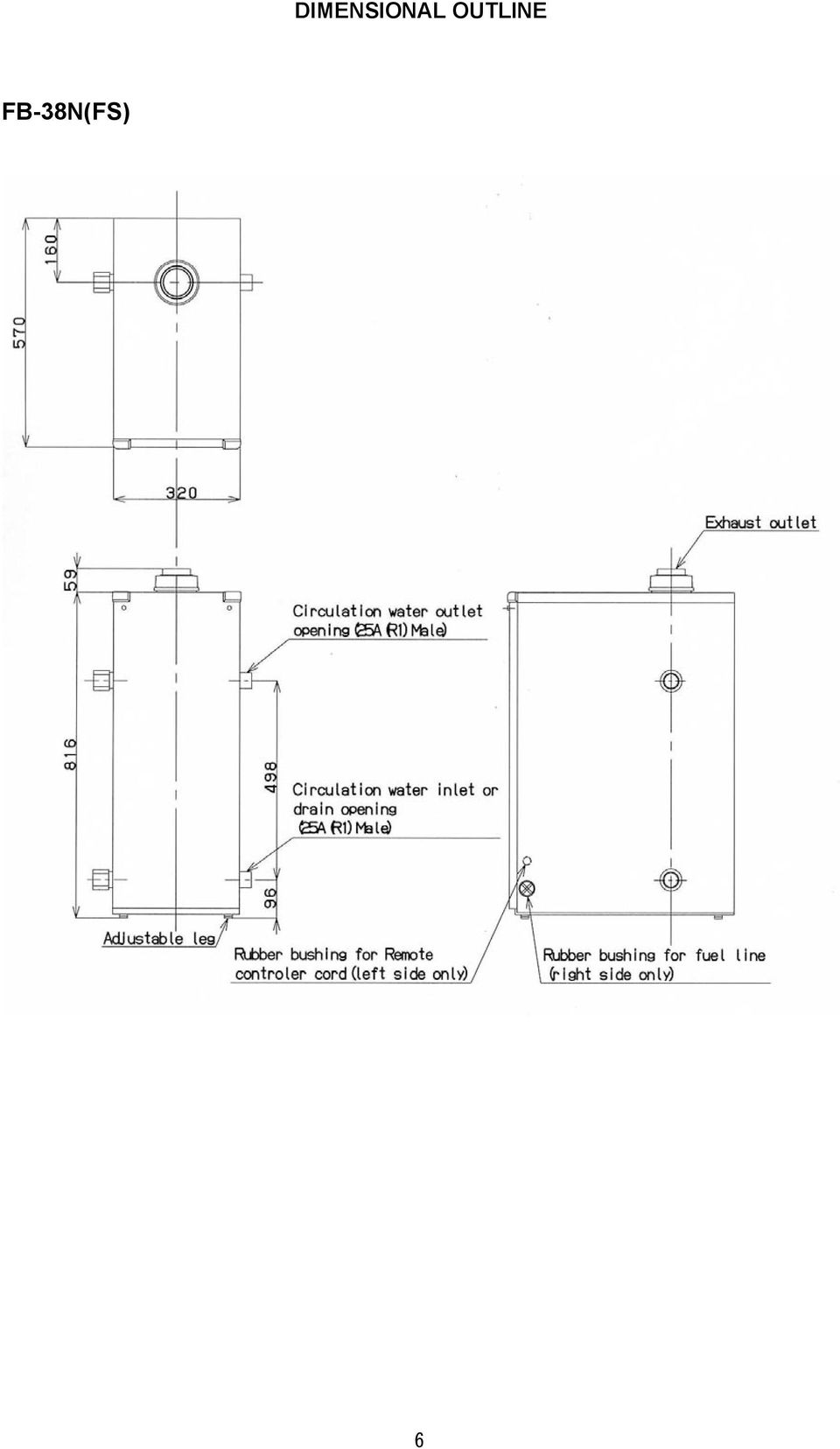
6 DIMENSIONAL OUTLINE FB-38N(FS) 6
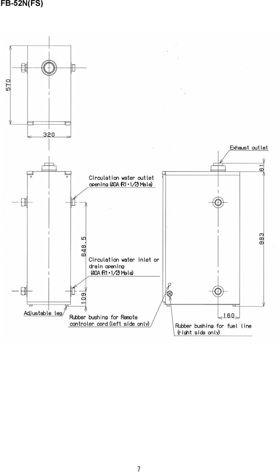
7 FB-52N(FS) 7
8 REMOTE CONTROL Power Lamp Power Switch Burner Lamp External Input Lamp Temp Select Button (UP) Display Temp Select Button (Down) POWER LAMP - constant: In operation - extinction: Shutdown BURNER LAMP - constant: In operation - extinction: Extinguished POWER SWITCH: TEMP SELECT BUTTON: Turns the unit on or off. Digit will change from 1 to 9 by pressing button (UP). Digit will change from 9 to 1 by pressing button (Down). Adjusts the temperature of the circulating water; 1: Approx. 20 C 6: Approx. 55 C 2: Approx. 30 C 7: Approx. 60C 3: Approx. 40 C 8: Approx. 70 C 4: Approx. 45 C 9: Approx. 80 C 5: Approx. 50 C EXTERNAL INPUT LAMP: You can connect the optional external input terminal lead wire. When connecting the unit to the external input terminal, input status will be displayed. 8

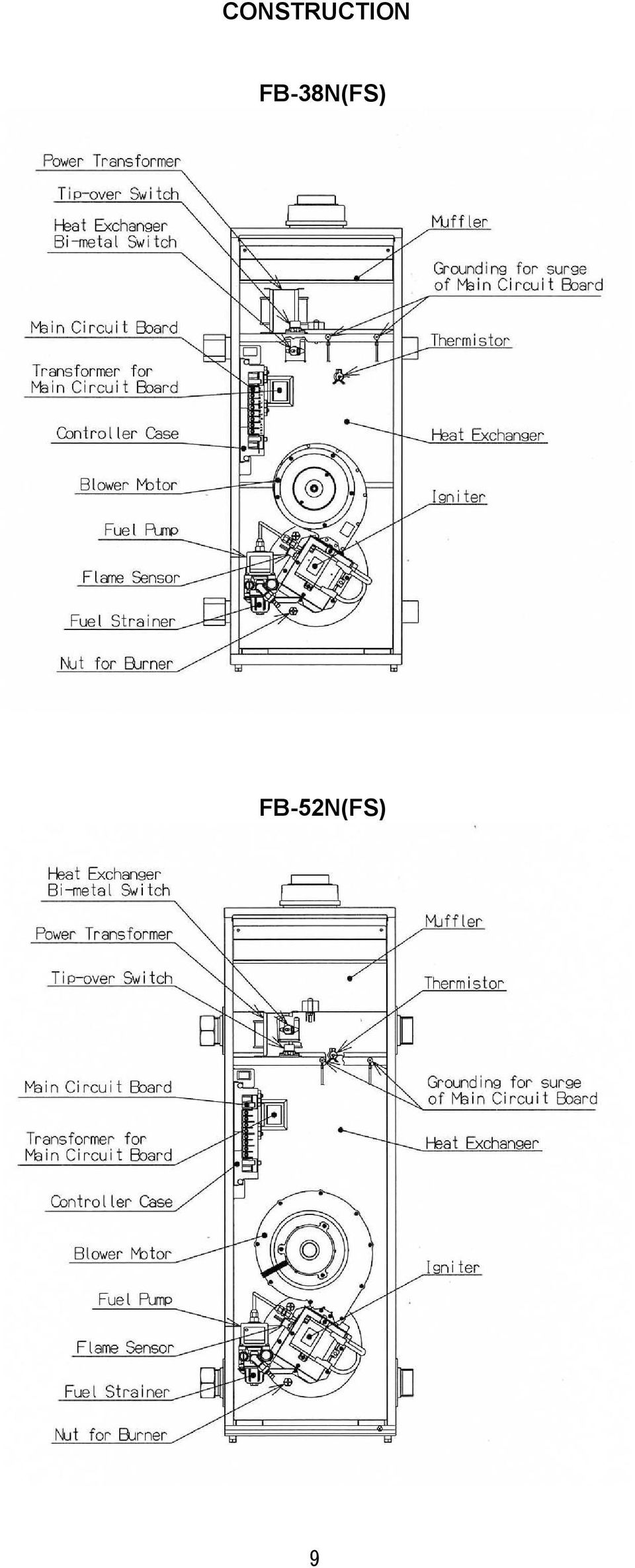
9 CONSTRUCTION FB-38N(FS) FB-52N(FS) 9
10 SECTION C: FUEL GUIDE The Water Heater is designed for use with water clean and high quality kerosene only. Use of low-quality kerosene will cause burner performance to drop, leading to abnormal combustion and reduced the unit life. Always store your fuel in a separate area from where you store gasoline for your power equipment to avoid accidental use of gasoline in your water heater. What to Buy... ALWAYS: ALWAYS: NEVER: NEVER: How to Store It... ALWAYS: ALWAYS: NEVER: NEVER: NEVER: Clean and high-quality KEROSENE. Fuel free of contaminants, water or cloudiness. Gasoline, alcohol, white gas, camp stove fuel or additives. Yellow or sour-smelling fuel. Store in a clean container, clearly marked KEROSENE. Store away from direct sunlight, heat sources or extreme temperature changes. In a glass container, or one that has been used for other fuels. For longer than six months. In the living space. Why It is Important... Pure, clean kerosene is essential for safe and efficient water heater operation. Poor quality or contaminated kerosene can cause: - Excess tar deposits on burner and flue pipe - Incomplete combustion - Reduced unit life Use of a highly volatile flammable fuel such as gasoline can produce uncontrollable flames, creating a severe fire hazard. 10

11 SECTION D: OPERATION FUELING WARNING: Use KEROSENE only. Never use gasoline, thinner, benzene, light oil or waste oil. CAUTION: Make sure that the fuel is clean and free from dirt and water. Water and dirt may cause combustion failure and shorten the life of components such as the Fuel Pump. Be sure to refuel before the Tank runs out. Avoid having the Fuel Tank and Fuel Pipe run empty. REMOVING AIR TRAP When operating for the first time or when refueling an empty Tank, air may be trapped in the Fuel Pipe, making ignition difficult. In this situation, follow the procedures below: 1. Turn the unit off by pressing POWER SWITCH. Disconnect the Power Supply Cord. 2. Release the two (2) screws from the Front Panel and remove the Front Panel. 3. To catch the fuel which will drain out, put a small container under the strainer. 4. Loosen the Screw on top of the Fuel Strainer. Immediately wipe off any spilled fuel. 5. Remove the trapped air thoroughly. Failure to remove all the air will cause improper ignition and may extinguish the unit. 6. Tighten the Screw after removing trapped air. 7. Plug into the receptacle. Tunn the unit on by pressing POWER SWITCH. NOTE: In the event of an ignition failure, Turn the unit off by pressing POWER SWITCH and after 5 seconds press POWER SWITCH once again. INSPECTION BEFORE OPERATION 1. Check for water leaks in the Circulation Pipes. 2. Be sure there is a sufficient amount of fuel in the Fuel Tank and that there are no leaks in the Fuel Pipe. 3. Be sure the Power Supply is properly connected and grounded to the unit. 4. Be sure the area around the Water Heater is clear of flammable materials such as gasoline, thinner or flammable vapors. 5. Be sure the Exhaust Pipes are securely connected and that there are no leaks. 11
 screws from the Front Panel and remove the Front Panel. 3.")
12 OPERATION CAUTION: The excessive high temperature setting increases the risk of scald injury. (Thermal burn at low temperature) 1. Open the Fuel Tank Valve. 2. Press POWER SWITCH of Remote Controller. Opration lamp will come on and display indicates 7. Automatic operation is based upon the temperature of water inside the heat exchanger. BURNER lamp is lit when the burner is in its operation mode. NOTE: When you first use your water heater after installing, the display indicates 7. In other case the display indicates the previous setting number. IF IGNITION FAILURE OCCURES 1. When first using the Water Heater after it is installed or refueled, it may not be ignited due to air left in the Fuel Pipe. If so, remove air from the Fuel Pipe as described in the previous section. 2. Make sure that the Fuel Tank is free of water. If not, remove water through the Drain Valve. If there is water inside of Drain Cup, remove water completely. 1. Press POWER SWITCH of Remote Control. 2. Close the Fuel Tank Valve. TURNING UNIT OFF ADJUSTING WATER TEMPERATURE The temperature of the circulation water is raised or lowerd by pressing the temperature select buttons. To adjust the water temperature, use the Λ button to set the temperature to a higher setting and the V button to lower the temperature. The setting temperature (setting display) remains even though the power failure occurs. The display indicates 1 to 9. 9 is the maximum high temperature setting. Setting Display and Circulation Water Temperature Setting Display Circulation Water Temp. 20 C 30 C 40 C 45 C 50 C 55 C 60 C 70 C 80 C 12

13 DIFFERENTIAL SWITCH AND DIP SWITCH CAUTION: Please consult your dealer on the operation of DIP Switch. By the Differential Switch on the Main Circuit Board, the temperature of circulation water is controlled in the range of 2 C differential, 6 C differential, 9 C differential or 12 C differential. NOTE: If the wide differential is selected, the cycle frequency of ignition and extinguishments of the Burner will be reduced. The position of DIP Switch is set to 6 C differential from factory. PREVENTING FREEZE UP In order to prevent any kind of damage or leaks caused by freezing, make sure if the antifreeze fluid of adequate concentration contains in the circulation water regardless of being used in a cold region or in a warm or hot region. - Change the circulation water every 2 years. LONG TERM INACTIVITY When leaving the unit unused over a long period of time, disconnect the Power Supply Cord after turn the unit off by pressing the POWER SWITCH. 13

14 SECTION E: ROUTINE MAINTENANCE INSPECTION AND MAINTENANCE WARNING: RISK OF INJURY FROM MOVING PARTS AND ELECTRICAL SHOCK. Disconnect the Power Supply Cord before inspecting and servicing unit. All repairs should be left to professionals. RISK OF BACKFIRE AND INDOOR POLLUTION. Before operation make sure the Exhaust Pipe is free of snow, icing, leaves, bird s nest or strong drafts. CAUTION: RISK OF BURN INJURY. Do not touch the Exhaust Pipe Top and the Exhaust Pipe. When inspecting, ALWAYS do the following. a. Press the Power Switch to turn off. b. Disconnect the Power Plug from the Receptacle. c. Close the Fuel Tank Valve. When inspecting, NEVER do the following. a. Do not remove the Thermistor. b. Do not remove the Tip-over Switch. c. Do not adjust the pressure of the Fuel Pump. INSPECTION AND MAINTENANCE ITEMS 1. FLAMMABLE IN THE ENVIRONMENT (REGULARLY) Remove all flammable material from the area. 2. FUEL LEAKS (REGULARLY) Always check for fuel leaks. Clean off spilled fuel thoroughly when lubricating fuel. If a leak is found, shut down the unit until the problem is corrected. 3. FUEL PIPE INSPECTION (REGULARLY) Check for fuel leaks from the Fuel Pipe. Replace it if any cracks or leaks are found. 4. WATER LEAKS (REGULARLY) Check the heat exchanger for water leaks. Always correct if found. 5. ODOR OR SOOT (REGULARLY) Check the Exhaust Pipe top for abnormal odor and accumulated soot. Consult your dealer if it Is found. 6. DUST (ONCE A MONTH) Check for dust inside of the unit and the bottom (base). 7. WATER INSIDE THE FUEL TANK (ONCE A MONTH) Remove any water or waste particles that accumulate inside the Fuel Tank. 8. FUEL STRAINER (ONCE A MONTH) Vibration, noise, ignition and combustion failure could be caused by water or waste particles in the Fuel Strainer. Clean the Fuel Strainer by kerosene once a month. 14

15 9. PRESSURE RELIEF VALVE (ONCE A MONTH) The Pressure Relief Valve may become immovable at times due to corrosion of pipes or mineral deposits In the pipes. Pull up the lever of the Pressure Relief Valve every month and make sure the Valve is movable. 10.PLUG AND RECEPTACLE (ONCE A MONTH) Make sure the Plug is free of dust. Be sure Plug fits Receptacle securely. 11.BURNER INSPECTION (ONCE SIX MONTHS) Check the burner and combustion area for soot. Clean if found. 12.GASKETS AND SEALING (ONCE SIX MONTHS) Check for water leaks caused by improper sealing of the Circulation Water Pipe. Consult your dealer if there are leaks. 13.FLAME SENSOR (PHOTOELECTRIC CELL) (ONCE SIX MONTHS) a. Take out the Flame Sensor which is located to the left of the Burner inside the Cabinet. b. If the receiving surface of the photoelectric cell of the Flame Sensor becomes dirty or contaminated, the unit will not operate properly. The receiving surface of photoelectric cell should be wiped with a soft cloth every 6 months. 14.BLOWER MOTOR (ONCE SIX MONTHS) Make sure there is no dust on the blower motor fan. 15.EXHAUST PIPE (ONCE A YEAR) A clogged Exhaust Pipe will cause improper combustion. Inspect for any clogging or soot accumulation should be done at least once every year. Make sure not to place combustibles in the Exhaust Pipe area. 15
 Check for water leaks caused by improper sealing of the Circulation Water Pipe. Consult your dealer if there are leaks. 13.")
16 SECTION F: TROUBLESHOOTING WARNING: RISK OF INJURY FROM MOVING PARTS AND ELECTRIC SHOCK. Disconnect the Power Supply Cord before servicing unit. All repairs should be left to professionals. Do not re-use the unit until the cause of the problems have been determined. CAUTION: RISK OF BURN INJURY. Do not touch the unit and the Heat Exchanger while in hot. If there Is any abnormality, determine for the causes from the list below and perform the specified measure. Consult your dealer if problems cannot be corrected from this chart. At the start of operation While in operation After stop PROBLEM POWER LAMP FAILS TO TURN ON ALARM LAMP LIGHTS AFTER TURNING ON. BLOWER MOTOR OPERATES BUT IGNITION FAILS. EXTINGUISHED AFTER IGNITION NOISE FROM FUEL PUMP NOISY COMBUSTION HOT WATER TEMP TOO LOW SOOT ACCUMULATION ERROR CODE CAUSE SOLUTION - Disconnected power supply cord Connect power supply cord. E3 E9 E9 E2 E7 E7 E7 E7 E7 E7 E7 E6 E6 E6 E6 Thermistor malfunction Bi-metal switch activated Thermal fuse activated Flame sensor malfunction or light is received on the receiving surface of photoelectric cell Abnormal location and adjustment of electrode Igniter malfunction. Abnormal lowering of electrical voltage Out of fuel Trapped air in fuel pipe. Clogged fuel strainer Circuit board malfunction Stained photoelectric cell Trapped air in fuel pipe Excessive air for combustion Flame sensor malfunction 16 Replace it. Reset after eliminating cause. Replace it. Repair or replace it. Consult your dealer. Consult your dealer. Contact electricians. Check fuel gauge on fuel tank; refuel. Remove the trapped air. Clean strainer. Consult your dealer Clean it. Remove the trapped air. Consult your dealer. Replace it. Remove air. Consult your dealer. Consult your dealer. Consult your dealer. Consult your dealer. - Air lock in fuel line Clogged intake line and pump - Fuel flow too much Fuel flow too little Improper installation of Exhaust Pipe - Thermistor malfunction Consult your dealer. - Dusty blower motor fan Improper installation of flue pipe Fuel flow too much Consult your dealer. Re-install properly. Consult your dealer. DOES NOT HEAT - Power switch of remote controller is not pressed Leakage from circulation part Insufficient removing air Press Power switch. Consult your dealer. Consult your dealer. FUEL LEAKAGE FROM FUEL PIPE - Loose connection of fuel pipes Consult your dealer. WATER LEAKAGE - Water leakage from heat Consult your dealer. exchanger (Heat exchanger malfunction)

17 ERROR CODE IN DISPLAY When the water heater is malfunctioned, the unit stops the operation automatically and Display indicates Error Code ( E & Number ) alternately by flashing. Display CAUSE RESULT E + 0 E + 2 E + 3 E + 4 E + 5 E + 6 E + 7 E + 8 E + 9 Disconnected model setting jumper terminal Flame sensor detected flame before ignition Disconnected thermistor High limit switch activated Tip-over switch activated Extinguished after ignition No ignition Blower motor malfunction Heat exchanger bi-metal switch or Thermal fuse activated Out of fuel Refuel Operation stops and operation lamp and display are flashing. E + E + Ξ E + Malfunction of remote controller or remote controller cord NOTE: To restart the unit, tunr the unit off by pressing POWER SWITCH and after 5 seconds press POWER SWITCH to turn it on once again. NOTE: Press the Reset Button of Heat Exchanger Bi-metal Switch to reset the unit when Heat Exchanger Bi-metal Switch is activated. Make sure to disconnect the Power supply cord before pressing the Reset Switch of Heat Exchanger Bi-metal Switch. 17

18 WIRING DIAGRAM Terminal Block for Remote Contorl Model Selecting Jumper Open Terminal Open Terminal Open Terminal Open Terminal Open Terminal Open Terminal Open Terminal Open Terminal B: Blue O: Orange Y: Yellow W: White R: Red K: Black 18

19 TOYOTOMI CO., LTD. 5-17, MOMOZONO-CHO, MIZUHO-KU, NAGOYA, JAPAN New 9/08 Printed in Japan 19

20 Kerosene-Fired Water Heater Installation Manual MODEL FB-38N(FS) / FB-52N(FS) IMPORTANT THIS APPLIANCE SHOULD BE INSTALLED BY A LICENSED, AUTHORIZED PERSON(S) DUE TO THE NECESSITY OF MAKING ELECTRICAL, WATER AND FUEL CONNECTIONS. RETAIN THIS MANUAL FOR FUTURE REFERENCE. CHECK LOCAL CODES AND ORDINANCES FOR PERMITTED USE. CAUTION THIS WATER HEATER SHALL NOT BE USED FOR COMMERCIAL USE OR FOR ANY PURPOSES OTHER THAN HOT WATER SUPPLY USES. OTHER USAGE MAY CAUSE A MALFUNCTION OR SHORTEN ITS SERVICE LIFE. DO NOT REMOVE THE RATING PLATE AND LABELS FROM THE WATER HEATER UNIT. [CONTENTS] SECTION A: Wiring for Water Heater Safety Tips for Installation... 2 Wiring Terminal Block for Remote Control SECTION B: Temperature Control (Differential Unpacking... 3 Switch and Dip Switch) Standard Installation Parts... 3 SECTION D: SECTION C: How To Install The Exhaust Pipe and Installation Exhaust Pipe Top Selecting a Location Installation of Exhaust Pipe and Level Adjustment... 4 Exhaust Pipe Top Fuel Tank Installation Check for Exhaust Pipe and Fuel Pipe Installation... 5 Exhaust Pipe Top Removing Air Trap Plumbing SECTION E: Electrical Wiring Test Run Installing Remote Control Preparation Wiring for Remote Control Cord.. 11 Operation

21 2
22 SECTION A: SAFETY TIPS FOR INSTALLATION BE SURE TO FOLLOW THE FOLLOWING INSTRUCTIONS. The instructions which are contained in this manual are classified into the following two types, which are WARNING and CAUTION. These instructions are intended to provide important information for safe operation. WARNING indicates the possibility of causing the user a fatal accident or serious injury if the water heater is incorrectly operated. CAUTION indicates the possibility of causing the user injuries or material damages if the water heater is incorrectly operated. WARNING 1. Never use any fuel other than water-clear and high quality of kerosene. NEVER USE GASOLINE! Use of such fuels can result in an explosion and/or fire and cause injury. 2. Improper installation, adjustment, modification, or service and maintenance by an unauthorized person may cause SERIOUS UNIT DAMAGE, BODILY INJURY, HAZARD OR PROPERTY DAMAGE. This unit should be installed by a licensed, authorized person(s) due to the necessity of making electrical, water and fuel connections. Refer to the installation manual and the operation and maintenance instructions for assistance, or consult your dealer for further information. 3. HAZARD OF ELECTRICAL SHOCK! Before removing any access panels of water heater for service, make sure the electrical supply to the water heater is shut off. Failure to do this may result in HAZARD, SERIOUS BODILY INJURY, OR PROPERTY DAMAGE. 4. Check and comply with all state and local codes that may apply to water heater(s) before beginning the installation. 5. This water heater is designed to be used no more than 1,300 m above sea level. The water heater may have a failure of combustion at a high altitude. Ask your local dealer for using at altitudes higher 800 m ~ 1,300 m above sea level. 6. RISK OF INDOOR AIR POLLUTION AND FIRE. Be sure the exhaust pipe is properly installed and connected. Aluminum tape provided may be used for sealing exhaust pipe connections. CAUTION 1. Keep the area around the unit clean and free of flammable materials. 2. RISK OF FIRE AND ELECTRIC SHOCK. Do not apply any excessive force or pressure to the power supply cord. Make sure the plug is free of dust. Be sure plug fits receptacle securely. 3
23 SECTION B: UNPACKING UNPACKING 1. Unpack the unit carefully. 2. Check to see if there are any loose screws that may have occurred in transit. 3. Take accessories and the Operation and Maintenance instructions out of the carton. STANDARD INSTALLATION PARTS The following standard installation parts are enclosed with unit. 1. Exhaust Pipe Top (1 pc.) 2. Rubber Fuel Hose (1 pc.) 3. Hose Band (2 pcs.) 4. Remote Control (1 set) 5. Remote Control Cord (3 m) 6. Adhesive Tape (2 pcs.) 7. Wooden Screw (2 pcs.) SECTION C: INSTALLATION WARNING: WARNING: WARNING: This unit must be installed in accordance with these instructions, local codes, ordinance and/or in the absence of local codes, the latest edition of the national fire protection association code. Check and comply with local codes that may apply to Water Heater(s) before beginning the installation. This unit should be installed by a licensed, authorized person(s) due to the necessity of making electrical, water and fuel connections. SELECTING A LOCATION Select a place to install the Water Heater where water pipes, electric supply, and surrounding surfaces will be at safe and noise prevention distances. 1. Select a place which is free of moisture, water spills, pools or snow. 2. Select a place which draining can be done easily. 3. Select a place which the Fuel Tank can be installed safely. 4. Select a place which is free of combustible substances. 5. The surrounding walls should be finished with non-flammable materials (concrete block, mortar, or plaster are allowable). 6. The floor on which the Water Heater is installed must prevent intensive vibrations or shock and must be strong enough to bear the weight of the water heater. 4
24 7. Select a place where proper maintenance and control can be provided for the unit after installation. 8. Select a place sheltered from weather. 9. Install the unit on a non-flammable surface in a stable position. 10. It is important to keep enough clearance for the purpose of maintenance, repair and possible servicing. 11. The Exhaust Pipe is free of snow, icing, leaves, bird s nest or strong drafts. 12. Before making a hole in your wall for the Exhaust Pipe, make sure the area is free of electrical wires, gas pipes and other obstacles. 13. Select a place that can draw in sufficient air for combustion. The air intake hole should be placed in a spot can draw in outside air near the floor. [FB-38N(FS)] Effective hole area 450 cm 2 x 2 locations Type of ventilation hole Aperture factor Existing ventilation hole ara Metal ventilation hole 50% 900 cm 2 Wooden ventilation hole 40% 1125 cm 2 [FB-52N(FS)] Effective hole area 600 cm 2 x 2 locations Type of ventilation hole Aperture factor Existing ventilation hole ara Metal ventilation hole 50% 1200 cm 2 Wooden ventilation hole 40% 1500 cm Select a place which maintain sufficient clearance to prevent fire. The clearance between the Water Heater and combustible objects should be maintained as illustrated in the figure. LEVEL ADJUSTMENT After positioning the Water Heater, adjust the level with the 4 adjusting legs located at the Water Heater bottom and make sure the position of the unit is leveled by using a plumb bob. 5
25 FUEL TANK INSTALLATION The fuel tank must be purchased separately and installed by a qualified fuel supply technician. NOTE: Fuel tank installation must comply with locally applicable codes. Check with local building officials. NOTE: Keep the fuel tank away from direct sunlight, high temperature, dust, rain and fire, and take preventive measures against falling during an earthquake. NOTE: The fuel tank should be installed on non-flammable objects, and kept level to prevent the unit from falling or shaking. NOTE: The fuel tank should be installed on a base finished with non-flammable objects (concrete, mortar or block). The legs of fuel tank should be secured with anchor bolts (4 locations) to prevent falling or shaking. FUEL PIPE INSTALLATION Insert the rubber fuel hose to the fuel valve connected with the fuel tank, and tighten by the hose band. NOTE: Do not apply heavy pressure on the fuel hose. To prevent an air lock in the fuel line, the fuel line should not be deformed. NOTE: Only regular pipe should be used as a fuel pipe. NOTE: To install a rubber fuel hose, if the bending radius is too small, cracks will occur in a short time because of stress on the inside of the rubber, and an oil leakage may occur. Be sure to maintain a bending radius more than 100 mm, and avoid torsion. NOTE: Select a place protected from direct sunlight. When a ruuber fuel hose is exposed to UV rays, degradation will be accelerated. NOTE: For outdoor installation, be sure to use a metal pipe (copper pipe with an external diameter of 8 mm ) as a fuel pipe. CAUTION: If metal fuel pipe is laid-out, be sure to clear away scraps or chips from the pipe which are produced during cutting or assembling. Leaving these scraps in the pipe may cause problem in the fuel pump. 6
26 REMOVING AIR TRAP When operating for the first time or when refueling an empty Tank, air may be trapped in the Fuel Pipe, making ignition difficult. In this situation, follow the procedure below: 1. Turn the unit off by pressing POWER SWITCH. Disconnect the power supply cord. 2. Release the two (2) Screws from the Front Panel and remove the Front Panel. 3. To catch the fuel which will drain out, put a small container under the Fuel Strainer. 4. Loosen the Screw on top of the Fuel Strainer. Immediately wipe off any spilled fuel. 5. Remove the trapped air thoroughly. Failure to remove all the air will cause improper ignition and may extinguish the unit during operation. 6. Tighten the Screw after removing trapped air. 7. Reconnect the Power Supply Cord. Turn the unit on by pressing POWER SWITCH. NOTE: In the event of an ignition failure, turn the unit off by pressing POWER SWITCH and after 5 seconds press POWER SWITCH to turn it on once again. PLUMBING The unit should be equipped with floor heating panels or radiator (convector). NOTE: Select a place where the Heating Piping for the Water Heater and radiator can be shortened as much as possible. NOTE: Make sure the piping for the radiator is laid-out properly, and also check for leakage with a pressure test. NOTE: Circulation Pump capacity should be selected in accordance with the water head loss caused by the required maximum flow and the longest piping. CLOSED CIRCUIT PIPING EXAMPLE Air Release Valve Tee Header Header Valve Expansion Tank Union Circulation Pump Pressure Differential Relief valve Pressure Valve Air Release Valve Valve Bypass Hot Water (Outlet) Header Valve Air Separator Water Supply Valve 7 Drain Valve Header Hot Water (Inlet)
27 NOTE: Be sure to install the Pressure Relief Valve in the proper direction. CAUTION: Be sure to assemble the piping system at a pressure than 100 kpa because the maximum water pressure is 100 kpa. If not, the heat exchanber may be damaged. Be sure to install a Pressure Relief Valve in the heating water piping on the inlet side of the Circulation Pump. CAUTION: Use a pipe with a nominal diameter of 25A (R1) [FB-52N(FS): 40A (R1)] between the Water Heater and header. If not, air will become trapped and result in insufficient filling of Antifreeze Solution. This condition may lead to create holes on the heat exchanger. 1. Install heaat insulation material on the hot water piping to prevent heat loss. 2. Be sure to use Antifreeze Solution specified by dealer with proper mix proportion for circulation water to prevent freezing and corrosion. 3. Copper or stainless steel pipe should be used for the main and branch pipes. 4. Be sure to connect a hot water pipe with the Semi-closed Expansion Tank or Closed Expansion Tank, and install at the inlet side of the Circulation Pump. 5. Install an Air Separator and Air Release Valve in the hot water pipe to release air inside of the pipe. 6. Be sure to install a Bypass circuit. (Closing the hot water pipe with a thermal valve or temperature control valve may cause problems in the Circulation Pump.) 7. Be sure to install unions in the hot water inlet and outlet sides for the purpose of maintenance. 8
28 SEMI-CLOSED / CLOSED EXPANSION TANK SELECTION NOTE: The Semi-closed Expansion Tank (optional) should be selected in accordance with the total water volume contained in the hot water piping system. NOTE: Refer to the formula below or the manufacturer s formula when selecting the closed expansion tank. [Calculation formula for Closed Expansion Tank] V = {(P ) / (P 2 P 1 )} x 1.1 ε V 0 (When the discharge pressure of he Pressure Relief Valve on the hot water pipe indicates 95 kpa) V: Capacity of Closed Expansion Tank (lit.) V 0 : Total water volume contained in hot water piping system (lit.) ε: Circulation water expansion rate P 1 : Air injection pressure of Expansion Tank (kpa) The air injection pressure should be selected at the pressure, which is 10 to 20 kpa greater than the maximum static pressure that is applied on the Expansion Tank (maximum value between Expansion Tank and radiator). P 2 : Discharge Pressure of Pressure Relief Valve (kpa) V 0 (lit.) = Heat exchanger capacity of Water Heater + retained water volume in radiator + retained water volume in pipe (see the following table.) Retained water volume in copper pipe per 1m Nominal Diameter Retained water volume (lit./ m) φ8 1/4 (8A) 3/8 (10A) 1/2 (15A) 3/4 (20A) 1 (25A) 1-1/4 (32A) 1-1/2 (40A) Retained water volume in city water pipe per 1m Nominal diameter 1/2 3/ /4 1-1/2 (15A) (20A) (25A) (32A) (40A) Retained water volume (lit./m) Expansion rate of Mix proportion of 40% 50% Antifreeze Solution Antifreeze Solution (0~80 C) Expansion rate ε
29 WATER INJECTION AND AIR RELEASE FROM WATER HEATER PIPING (FOR CLOSED CIRCUIT PIPING) 1. Connect the water outlet of the floor cistern (selected by dealer) with the water inlet of the hot water pipe with a vinyl hose. 2. Connect the water inlet of the floor cistern with the city water outlet with a vinyl hose. 3. Antifreeze Solution specified by dealer should be used, and the density should be at a ratio of 40% to 50%, as shown in the table. Table of Antifreeze Solution composition ratio Freezing temp. Antifreeze Solution City water -10 C 40% 60% -20 C 50% 50% CAUTION: The rust proofing capability will be reduced if a Solution with a ratio less than 40% is used. [Calculation formula for required amount of Antifreeze Solution] Required amount of Antifreeze Solution (lit.) = {(Heat Exchanger Capacity of Water Heater) + (retained water volume in radiator) + (retained water volume in piping)} x Antifreeze Solution ratio (%) x Supply water into the fllor cistern, and then insert the Power Plug in the Receptacle. 5. Close the valve 1, ope the Drain Valve and Water Supply Valve on the Water Heater piping. 6. By supplying water in the Water Heater piping, inject the required amount of Antifreeze Solution as per article 3 into the floor cistern. 7. As soon as the circulation water is drained, close the Drain Valve and then open the Air Release Valve on the Water Heater piping to release air of the line. 8. Start the Circulation Pump to circulate water. 9. Close the Feed Valve after 10 minutes, and then disconnect the Power Plug. NOTE: If air is released with each circuit connected to the Water Heater piping, the air releasing will be more effective. 10. After air releasing, take off the vinyl hose between the floor cistern and Water Supply Valve. 10
30 WATER INJECTION AND AIR RELEASE FROM WATER HEATER PIPING (FOR SEMI-CLOSED CIRCUIT PIPING) SEMI-CLOSED CIRCUIT PIPING EXAMPLE 1. Antifreeze Solution specified by dealer should be used, and the density should be at a ratio of 40% to 50%, as shown in the table. Table of Antifreeze Solution composition ratio Freezing temp. Antifreeze Solution City water -10 C 40% 60% % 50% NOTE: The rust proofing capability will be reduced if a Solution with a ratio less than 40% is used. [Calculation formula for required amount of Antifreeze Solution] Requried amount of Antifreeze Solution (lit.) = {(Heat Exhanger capacity of Water Heater) + (retained water volume in radiator) + (retained water volume in piping)} x Antifreeze Solution ratio (%) x Inject the Antifreeze Solution as per article 1 into the Expansion Tank, and start Circulation Pump to release air from each circuit on the Water Heater line. 3. If the water level of Expansion Tank goes down, inject circulation water mixed with Antifreeze Solution until the water level does not go down. 11
31 ELECTRICAL WIRING WARNING: RISK OF FIRE AND ELECTRIC SHOCK. Make sure the power supply cord is disconnected to avoid any electric shock before servicing. Electric shock may cause serious injury. It is recommended that installation should be conducted by a licensed electrician. NOTE: If the power receptacle is not installed at the proper position, then contact the appropriate electrical company. 1. Power source: AC 230V, 50Hz single phase 2. Use or install a power receptacle that is rated for this power supply. 3. A receptacle equipped with a grounded breaker should be used to supply the power. If a grounded breaker is not equipped, then contact the appropriate electrical company. 4. For a receptacle that is not the rainproof type, install it within the shaded area in the figure, or prepare a device to keep out the rain. 5. The length of the power cord is 2 m. The power cord should be free from damage, bundling, and sharp bends and not placed under a heavy object. If the power cord is installed outdoors, then select a place sheltered from rain water, and pass it through a conduit. INSTALLING REMOTE CONTROL NOTE: Select a place that is free from rainwater, high-temperature and humidity, and dust. Be aware of tripping over the cord, having the cord become caught on a door, or crushing the cord under heavy objects. DO not bundle the remote controller cord with a power supply cord or other electric equipment cords. Install the cord separately. Select a place for the installation that takes into account the cord length. 3 m remote control cord is attached. An extension cord up to 20 m for the remote control is permitted. WIRING FOR REMOTE CONTROL CORD 12
32 For Installation on the wall 1. For installation with the double-sided adhesive tape (2 pcs.) included in the carton box (1) Remove the screw on the Remote Controller Cover, and remove it from the base. (2) Attach the adhesive double-coated tape at the back of the base first, and then affix the base to the wall. (3) After the Y-shaped terminal of the Remote Controller Cord is screwed on to the terminal on the circuit of Remote Controller, then put the cord around the boss as shown in the figure. (4) Return the Remote Controller Cover to the base. 2. For installation with the wood screws (2 pcs.) included in the carton box (1) Remove the screw for the Remote Controller Cover, and remove it from the base. (2) Fix the base at the desired position by the attached screws (2 pcs.). (3) After the Y-shaped terminal of the Remote Controller Cord is screwed on to the terminal on the circuit of Remote Controller, then put the cord around the boss as shown in the figure. (4) Retrun the Remote Controller Cover to the base. 13
33 WIRING OF WATER HEATER (1) After making sure that the power supply cord is disconnected, remove the two (2) screws from the front panel and remove the front panel. Rubber bushing (2) Cut the rubber bushing on the left side panel by a cutter and insert the remote control cord. (3) Connect the terminal of the remote control cord to the terminal block for the remote control on the main circuit board case together with the terminal wired from the circuit board. (4) Fix the remote control cord on the cable clamp located under the rubber bush. the main circuit board. WIRING TERMINAL BLOCK FOR REMOTE CONTROL Main circuit board case Transformer Remote control cord Terminal block Connect the 2 (two) Y-terminals of the remote control cord on the terminal block with the screws by putting on the terminals of the lead wire (white) wired from the main circuit board. Make sure that each terminals are contacted correctly. 14
34 TEMPERATURE CONTROL (DIFFERENTIAL SWITCH AND DIP SWITCH) NOE: Make sure that the power supply cord is disconnected when the position of DIP Switch is selected. 1. The differential switch on the main circuit board controls the heat exchanger water temperature. The switch can be set at a delta (on/off) of 2 C, 6 C, 9 C or 12 C. A higher delta reduces burner short cycling. And you can set the maximum setting temperature at approx. 50 C, 60 C, 70 C or 80 C. 2. The position of DIP Switch is set to 6 C differential from factory. The maximum setting temperature is set to approx. 80 C at factory. If you like to change the differential, select the DIP Switch as follows. HOW TO SELECT DIP SWITCH NOTE: DIP Switch is located on the main circuit board. 1 Error History 2 Differential 3 4 Max. Temp. 5 Setting 6 7 High Altitude 8 (1) DIP Switch No. 1: Error history When turning the DIP Switch No.1 to OFF position at the operation switch off, the burner lamp will flash and it indicates when the error occurred by number of flashing times and the error code is displayed on the remote control. Example: In case that the error occurred two times before; (2) DIP Switch No. 2 and No.3: Temperature differential Differential 6 C 2 C Dip No. (Factory setting) 9 C 12 C 2 ON ON OFF OFF 3 OFF ON ON OFF (3) DIP Switch No. 4 and No.5: Maximum setting temperature Set Temp Dip No. 9 (80 C) (Factory setting) 8 (70 C) 7 (60 C) 5 (50 C) 4 ON ON OFF OFF 5 ON OFF ON OFF (4) DIP Switch No. 7: High altitude setting When using at high altitude (800~1300m), turn the DIP Switch No.7 to OFF position. This water heater will be not able to be used at more than 1300m higher altitude. 15
35 SECTION D: HOW TO INSTALL THE EXHAUST PIPE AND EXHAUST PIPE TOP WARNING: This unit is required to be installed the exhaust pipe and the exhaust pipe top. Make sure that Exhaust Pipe and Exhaust Pipe Top are properly connected. If it is disconnected, exhaust gas leak indoor during operation which may cause danger. INSTALLATION OF EXHAUST PIPE AND EXHAUST PIPE TOP 1. Diameter of Exhaust Pipe The diameter (internal) of the Exhaust Pipe for the Water Heater is 106 mm. NOTE: The exhaust pipe is optional. 2. Position of Exhaust Pipe and Exhaust Pipe Top Install so that the end of the Exhaust Pipe and Exhaust Pipe Top will conform to the setting standard as shown in item Exhaust Pipe Top Be sure to install the attached Exhaust Pipe Top to the end of Exhaust Pipe. 4. Limit of Exhaust Pipe extension The length of the Exhaust Pipe should not be more than 3 m with less than 3 bends. NOTE: The length of the Exhaust Pipe must comply with fire prevention measures, and be short as possible. NOTE: The Exhaust Pipe should be laid down transversely at a downward slope (1/50) to the Exhaust Pipe Top. NOTE: The Exhaust Pipe should be covered with the insulating cloth cover (option). 5. Clearance from combustible objects Install the Exhaust Pipe and Exhaust Pipe Top in accordance with the installation standard shown in item Hole section in roof 1. Use a non-flammable and insulated material for the section. 2. Use non-flammable insulation around the part placed under the roof by using non-flammable materials except for metallic materials. 3. Do not connect the pipes around the section of flammable wall or ceiling where the Exaust Pipe passes through. 4. Before making a hole in your wall or ceiling, make sure the area is free of electrical wires, gas and water pipes. 7. Fixing the Exhaust Pipe and Exhaust Pipe Top Fix the Exhaust Pipe by using a pipe bracket at intervals from 1.5 m to 2 m. Fix tightly the Exhaust Pipe Top by using a bracket and hung bracket so that it does not fall due to wind or vibration. 8. Joint seal Be sure to seal tightly the connection of the Exhaust Pipe and Exhaust Pipe Top by using the aluminum tape (local supply) to avoid exhaust gas leakage. 9. Matters concerning the fire prevention code Installation of the Exhaust Pipe and Exhaust Pipe Top must comply with the 16
36 local code concerning fire prevention. 10. Securing diagram of Exhaust Pipe and Exhaust Pipe Top installation NOTE: Put a semi-straight pipe or straight pipe in the Exhaust Pipe fitting hole at first, and lay transversely. NOTE: Select a place which is clear of combustible objects within 15 cm around the Exhaust Pipe Top, and 60 cm in the exhaust direction. And any opening such as the window or ventilation hole which can blow exhaust gas back indoors is not allowed on the wall as shown above. NOTE: Use corrosion and heat resistant steel. 11. Caution in areas of heavy snowall In a cold-district (heavy snowfall), select a place where the Exhaust Pipe Top is free from snow. In case the Exhaust Pipe Top is blocked or plugged, exhaust gas may leak indoors and cause a danger. NOTE: Clearance between ground surface and Exhaust Pipe Top should be increased as far as possible to avoid blocking the Exhaust Pipe Top. 17
37 CHECK FOR EXHAUST PIPE AND EXHAUST PIPE TOP WARNING: Installation of Exhaust Pipe and Exhaust Top as shown below may cause an accident. Be sure to check once again after installation. Be sure to correct by following the installation presented below as an example in which a dangerous situation and incomplete combustion may occur. 18
38 19
39 20
40 SECTION E: TEST RUN PREPARATION 1. Make sure the exhaust pipe is installed properly. 2. Make sure the fuel tank is installed properly. Make sure there is no fuel leakage. 3. Make sure there is no water leaking from piping. (Plumbing) 4. Make sure electrical connections and grounding are wired properly. 5. Make sure the floor is stable and can withstand strong vibration and the weight of a full water heater. 6. Make sure the area is free of flammable materials. 7. Check for air trapped in fuel lines. OPERATION 1. Open the fuel tank valve. 2. Press the power switch of the remote control to ON position. Power lamp goes on. 3. Make sure that the unit works properly. 4. To shutdown the water heater, press the power switch of the remote control to OFF position. 5. Close the fuel tank valve. 21
41 TOYOTOMI CO., LTD. 5-17, MOMOZONO-CHO, MIZUHO-KU, NAGOYA, JAPAN New 9/08 Printed in Japan 22
CARING FOR YOUR WATER HEATER
 http://waterheatertimer.org/troubleshoot-rheem-tankless-water-heater.html Water Heater Inspections CARING FOR YOUR WATER HEATER Venting System (Direct Vent Only) The venting system should be inspected
Trouble Shooting. Pump
 Trouble Shooting Pump Trouble Possible Cause Remedy Oil leaking in the area of water pump crankshaft Worn crankshaft seal, bad bearing, grooved shaft, or failure of retainer o-ring. Excessive play on crankshaft
Dehumidifier Users manual. For Models: DH45S DH65S
 Dehumidifier Users manual For Models: DH45S DH65S 950-0062-revD Jan. 9 2007 FORWARD The appearance of the units that you purchase might be slightly different from the ones described in the Manual, but
800-292-3279 916 638-0828
 800-292-3279 916 638-0828 http://easycleansystems.com/heaters/heater-parts.html VAL6 KBE5S and KBE5L Service manual KBE5S 1 2 Specifications Type VAL6 KBE5S Heat Output 111,000BTU/h Fuel Kerosene, Diesel
Air Conditioner Water Heater - A Product of HotSpot Energy LLC
 Air Conditioner Water Heater - A Product of HotSpot Energy LLC PLEASE READ THIS BEFORE YOU INSTALL THE UNIT 1. This air conditioner must be installed and/or repaired by a qualified technician. If you perform
Use and Care Manual. Model CPA12KH AIR CONDITIONER
 Use and Care Manual Model CPA12KH AIR CONDITIONER Introduction Thank you for choosing this air conditioner to provide you and your family with all of the "Home Comfort" requirements for your home, cottage
Wine Cooler with Thermo-Electric Cooling & Heating Technology
 Wine Cooler with Thermo-Electric Cooling & Heating Technology Model number: WC-0888H (8-bottles capacity) Instruction Manual Please read carefully and follow all safety rules and operating instructions.
Portable Air Conditioner
 Portable Air Conditioner Owner's Manual Model:3 in 1 12,000 Btu/h Series 3 Please read this owner s manual carefully before operation and retain it for future reference. CONTENTS 1. SUMMARY...1 2. PORTABLE
Split-type Air-Conditioner INSTALLATION MANUAL CONTENTS FOR INSTALLER MXZ-3A30NA MXZ-4A36NA ATTENTION. English. Français. Español
 Split-type Air-Conditioner MXZ-3A30NA MXZ-4A36NA INSTALLATION MANUAL Refer to the installation manual of each indoor unit for indoor unit installation. English Français Español ATTENTION This manual mentions
USER S, MAINTENANCE and SERVICE INFORMATION MANUAL
 CONTENTS SAFETY INFORMATION................ 2 FOR YOUR SAFETY....................... 2 SYSTEM OPERATION.................. 2 THERMOSTATS........................... 2 INTERMITTENT IGNITION DEVICE...........
NewAir AC-10100E / AC-10100H Portable Air Conditioner Owner s Manual PLEASE READ AND SAVE THESE INSTRUCTIONS
 NewAir AC-10100E / AC-10100H Portable Air Conditioner Owner s Manual PLEASE READ AND SAVE THESE INSTRUCTIONS ELECTRICAL SAFETY This appliance is for indoor use only. Always turn off the unit and unplug
Operating Instructions Split System Air Conditioner
 Operating Instructions Split System Air Conditioner Model No. Indoor Unit Type Indoor Unit Type Nominal Capacity 26 36 F2 Low Silhouette Ducted S-26PF2U6 S-36PF2U6 Connectable outdoor unit lineup This
USER S MANUAL HSC-24A
 AIRREX AIR CONDITIONER USER S MANUAL HSC-24A Thank you for purchasing an AIRREX AIR CONDITIONER. BEFORE operation please read this user s manual carefully. Keep this manual readily available. It is ESSENTIAL
USER INSTRUCTIONS FOR GET PORTABLE 12k BTU AIR CONDITIONER MODEL No. GPACU12HR
 USER INSTRUCTIONS FOR GET PORTABLE 12k BTU AIR CONDITIONER MODEL No. GPACU12HR CONTENTS Introduction Safety Notes Identification of parts Installation instructions Operation instructions Maintenance Troubleshooting
Instruction Manual. Image of SP-3015 & SP-3815. Important Safeguards. Automatic Dispensing Hot Water Pot with Reboil Function
 Important Safeguards READ ALL INSTRUCTIONS BEFORE USE. Instruction Manual Automatic Dispensing Hot Water Pot with Reboil Function Image of SP-3015 & SP-3815 SP-3015: 3.0L SP-3815: 3.8L SP-3017: 3.0L (Stainless
BATHROOM HEATER. User's Manual. Page 2...A515 Page 9...A716
 BATHROOM HEATER User's Manual Page 2...A515 Page 9...A716 BATHROOM HEATER User's Manual A515 SAVE THESE INSTRUCTIONS AND READ ALL INSTRUCTIONS BEFORE USING THE HEATER. Dear customers, Thank you for selecting
Tankless Water Heater
 Tankless Water Heater USER S INFORMATION MANUAL Models WGRTNG199 / WGRTLP199 WGRTCNG199 / WGRTCLP199 NOTICE: Westinghouse reserves the right to make product changes or updates without notice and will not
SERVICE MANUAL. Room Air Conditioner Multi Split Wall-Mounted Type Indoor. FSAI-Pro-91AE2 FSAI-Pro-121AE2 FSAIF-Pro-181AE2
 SERVICE MANUAL Room Air Conditioner Multi Split Wall-Mounted Type Indoor FSAI-Pro-91AE2 FSAI-Pro-121AE2 FSAIF-Pro-181AE2 NOTE: Before servicing the unit, please read this at first. Always contact with
Meaco 30L and Meaco 40L dehumidifier instruction manual
 Meaco 30L and Meaco 40L dehumidifier instruction manual Please read this instruction manual before using the dehumidifier and keep safe for future reference SAFETY INSTRUCTIONS PLEASE READ ALL INSTRUCTIONS
IMPORTANT INSTRUCTIONS & OPERATING MANUAL. Houston 50 Inch Electric Wall Mounted Fireplace Black / White
 IMPORTANT INSTRUCTIONS & OPERATING MANUAL Houston 50 Inch Electric Wall Mounted Fireplace Black / White Model Number:MFE5050BK Model Number:MFE5050WH Read these instructions carefully before attempting
SWIMMING POOL HEAT PUMP
 SWIMMING POOL HEAT PUMP Installation & User Manual Model HP40B HP50B HP65B Hayward Pool Products Canada, Inc. T: 1-888-238-7665 www.haywardpool.ca CONTENT I. Application 4 II. Features 4 III. Technical
TECHNICAL DATA & SERVICE MANUAL SPLIT SYSTEM AIR CONDITIONER INDOOR UNIT: AW52AL AW64AL AW52AL 387030095 AW64AL 0.8180.463.0 07/05
 TECHNICAL DATA & SERVICE MANUAL INDOOR UNIT: AW52AL AW64AL SPLIT SYSTEM AIR CONDITIONER Model No. Product Code No. AW52AL 387030095 AW64AL 387030096 0.8180.463.0 07/05 IMPORTANT! Please read before installation
Service manual. Website: www.andico.com.au CAUTION - BEFORE SERVICING THE UNIT, READ THE SAFETY - PRECAUTIONS IN THIS MANUAL.
 Website: www.andico.com.au Service manual CAUTION - BEFORE SERVICING THE UNIT, READ THE SAFETY - PRECAUTIONS IN THIS MANUAL. - ONLY FOR AUTHORISED SERVICE PERSONNEL. MODELS: MPK1-09CR-QB8 MPK1-12ER-QB6
NewAir AC-10000E, AC-10000H Portable Air Conditioner Owner s Manual PLEASE READ AND SAVE THESE INSTRUCTIONS
 NewAir AC-10000E, AC-10000H Portable Air Conditioner Owner s Manual PLEASE READ AND SAVE THESE INSTRUCTIONS BEFORE USE GENERAL SAFETY INSTRUCTIONS: ALWAYS OPERATE THE UNIT IN AN UPRIGHT POSITION AND PLACE
Installation Instructions for Alarm Module Kit A043F059
 Instruction Sheet 07-2013 Installation Instructions for Alarm Module Kit A043F059 1 Introduction The information contained within is based on information available at the time of going to print. In line
Portable Air Conditioner. OWNER S MANUAL Read these instructions before use. Model: MF08CESWW. Voltage rating: 115V~60Hz Power rating : 800W
 MODE ALARM Portable Air Conditioner OWNER S MANUAL Read these instructions before use 8 Model: MF08CESWW Voltage rating: 115V~60Hz Power rating : 800W Customer Support : 1-800-474-2147 For product inquiries
AIR-CONDITIONER SPLIT TYPE
 FILE NO. A08-016 SERVICE MANUAL AIR-CONDITIONER SPLIT TYPE RAS-M10PKVP-E, RAS-M13PKVP-E, RAS-M16PKVP-E, RAS-M18PKVP-E / RAS-M10PKVP-ND, RAS-M13PKVP-ND, RAS-M16PKVP-ND, RAS-M18PKVP-ND / RAS-3M26GAV-E1,
SL280UHV SERIES GAS FURNACE WARNING
 2010 Lennox Industries Inc. Dallas, Texas, USA 506677 01 11/2010 Supersedes 506409 01 SL280UHV SERIES GAS FURNACE Litho U.S.A. FIRE OR EXPLOSION HAZARD. Failure to follow safety warnings exactly could
USER INSTRUCTIONS FOR 10 LITRE PORTABLE DEHUMIDIFIER MODEL NO. DHMD102
 USER INSTRUCTIONS FOR 10 LITRE PORTABLE DEHUMIDIFIER MODEL NO. DHMD102 THANK YOU FOR CHOOSING YOUR NEW DEHUMIDIFIER. BEFORE USING THE UNIT READ THESE INSTRUCTIONS FULLY AND RETAIN THEM FOR FUTURE REFERENCE
Split Type Room Air Conditioner. KSWM units
 OWNER S MANUAL Split Type Room Air Conditioner KSWM units Please read the operating instructions and safety precautions carefully and thoroughly before installing and operating your room air conditioner.
OPTIONAL SLENDER REMOTE CONTROL
 DAIKIN ROOM AIR CONDITIONER Operation Manual OPTIONAL SLENDER REMOTE CONTROL BRC944A2B READ BEFORE OPERATION Safety Precautions...2 Names of Functions of Parts...4 Preparation before Operation...5 OPERATION
USER S MANUAL. Duct Type Series. Free Joint Multi Air Conditioner (Cooling and Heating) FUEA Series E S F I P D G DB98-29565A(1) ENGLISH ESPAÑOL
 FUEA Series E S F I P D G DB98-29565A(1) ENGLISH ESPAÑOL") USER S MANUAL Duct Type Series MH MH FEEA Series FUEA Series ENGLISH ESPAÑOL PORTUGUÊS E HNIKA DEUTSCH ITALIANO FRANÇAIS Free Joint Multi Air Conditioner (Cooling and Heating) E S F I P D G DB98-29565A(1)
USER S MANUAL Duct Type Series MH MH FEEA Series FUEA Series ENGLISH ESPAÑOL PORTUGUÊS E HNIKA DEUTSCH ITALIANO FRANÇAIS Free Joint Multi Air Conditioner (Cooling and Heating) E S F I P D G DB98-29565A(1)
CDS TROUBLESHOOTING SECTION I. VACUUM. 1.0. Weak vacuum at wand. Gauge reads normal (10hg to 14hg)
") CDS TROUBLESHOOTING SECTION I. VACUUM 1.0. Weak vacuum at wand. Gauge reads normal (10hg to 14hg) 1.1. Clogged hoses or wand tube. Disconnect hoses and carefully check for an obstruction. 1.2. Excessive
CDS TROUBLESHOOTING SECTION I. VACUUM 1.0. Weak vacuum at wand. Gauge reads normal (10hg to 14hg) 1.1. Clogged hoses or wand tube. Disconnect hoses and carefully check for an obstruction. 1.2. Excessive
AIR CONDITIONER INSTALLATION MANUAL
 INSTALLATION MANUAL AIR CONDITIONER Please read this installation manual completely before installing the product. Installation work must be performed in accordance with the national wiring standards by
Portable Air Conditioner. OWNER S MANUAL Read these instructions before use. Model: MM14CHCSCS
 Portable Air Conditioner OWNER S MANUAL Read these instructions before use Model: MM14CHCSCS Voltage rating: 120V~60Hz Power rating : 1400W(Cooling) Power rating : 1350W(Heating) Customer Support : 1-800-474-21477
Do not store or use gasoline or other flammable vapors and liquids in the vicinity of this or any other appliance.
 Condensing Water Heater Operation Manual Model NPE-180A/ 210A/ 240A NPE-180S/ 210S/ 240S * Lead Free Keep this manual near this water heater for future reference whenever maintenance or service is required.
Firewall. Propane flame projector Safety instructions and operating manual
 Firewall Propane flame projector Safety instructions and operating manual TBF-PyroTec GmbH Lichterfelder Str. 5A 21502 Geesthacht Tel.: +49(0)4152 157 9950 info@tbf-pyrotec.de www.tbf-pyrotec.de 1 Flame
Portable Air Conditioner. OWNER S MANUAL Read these instructions before use. Model: MM14CCS. Voltage rating: 115V~60Hz Power rating : 1400W
 Portable Air Conditioner OWNER S MANUAL Read these instructions before use Model: MM14CCS Customer Support : 1-800-474-2147 Voltage rating: 115V~60Hz Power rating : 1400W For product inquiries or support
OWNER S MANUAL FORCE 10 MARINE COMPANY 23080 HAMILTON ROAD RICHMOND, BC CANADA V6V 1C9 TEL: (604) 522-0233 FAX: (604) 522-9608
 522-0233 FAX: (604) 522-9608") Electric Water Heater OWNER S MANUAL FORCE 10 MARINE COMPANY 23080 HAMILTON ROAD RICHMOND, BC CANADA V6V 1C9 TEL: (604) 522-0233 FAX: (604) 522-9608 If your water Heater is Damaged or you have questions
Electric Water Heater OWNER S MANUAL FORCE 10 MARINE COMPANY 23080 HAMILTON ROAD RICHMOND, BC CANADA V6V 1C9 TEL: (604) 522-0233 FAX: (604) 522-9608 If your water Heater is Damaged or you have questions
Portable Air Conditioner. OWNER S MANUAL Read these instructions before use. Model: MN12CES / MN10CESWW
 Portable Air Conditioner OWNER S MANUAL Read these instructions before use 8 Model: MN12CES / MN10CESWW Voltage rating: 120V~60Hz Power rating : 1100W (MN12CES) Power rating : 900W (MN10CESWW) Customer
Wilo SP Series Submersible Sump Pumps ECS. ECS19-15.25 ECS22-15.33 ECS24-15.50 Installation and operating instructions
 Wilo SP Series Submersible Sump Pumps ECS ECS19-15.25 ECS22-15.33 ECS24-15.50 Installation and operating instructions PREINSTALLATION CHECK Inspect this pump before it is used. Occasionally, pumps can
orlando OWNER S MANUAL
 orlando OWNER S MANUAL 2 Assembling & operating manual Orlando 30 mbar - PORTABLE GAS BARBECUE 1. 2. 3. Improper installation, adjustment, alteration, service or maintenance can injury or property damage.
BC & BCH SERIES INDOOR / OUTDOOR INSTALLATION
 Air Conditioning Central Heating & Cooling BC & BCH SERIES INDOOR / OUTDOOR INSTALLATION INSTALLATION AND SERVICE MANUAL 2 PROJECT: ADDRESS: MODEL: SERIAL NUMBER: INSTALLER: ADDRESS: PHONE NUMBER: INSTALLATION
MICA HEATER INSTRUCTION MANUAL Model No: UHM-786 230V 50Hz 2200W
 MICA HEATER INSTRUCTION MANUAL Model No: UHM-786 230V 50Hz 2200W Safety Precautions To reduce the risk of personal injury or damage to property, basic safety precautions must be observed including the
Please read this owner s Manual carefully before operating the unit. - Cooling - Heating - Dehumidifying - Fan
 Please read this owner s Manual carefully before operating the unit. - Cooling - Heating - Dehumidifying - Fan TABLE OF CONTENTS INTRODUCTION 2 IMPORTANT SAFEGUARDS...2 PACKAGE CONTAINS..2 NAMES OF PARTS.3
IMPORTANT SAFETY INSTRUCTIONS WARNING READ AND SAVE THESE OPERATING AND SAFETY INSTRUCTIONS BEFORE USING THIS HEATER.
 THERMAWAVE CERAMIC HEATER Model HZ-850 Series Model HZ-860 Series IMPORTANT SAFETY INSTRUCTIONS WARNING READ AND SAVE THESE OPERATING AND SAFETY INSTRUCTIONS BEFORE USING THIS HEATER. Warning Failure to
How To Use A Power Supply Unit (Upu)
") BRAVER UPS (Uninterruptible Power System) User s Manual Safety CAUTION! This UPS utilizes voltages that may be hazardous. Do not attempt to disassemble the unit. The unit contains no user replaceable parts.
BRAVER UPS (Uninterruptible Power System) User s Manual Safety CAUTION! This UPS utilizes voltages that may be hazardous. Do not attempt to disassemble the unit. The unit contains no user replaceable parts.
ALL IN ONE. Heat Pump Water Heater
 ALL IN ONE Heat Pump Water Heater INSTALLATION AND OPERATION INSTRUCTIONS Please read this user s manual carefully before operate the unit. www.airtradecentre.com CONTENTS A. IMPORTANT REMARKS ------------------------------------------------------------------------------------------------
SPLIT WALL MOUNTED TYPE AIR CONDITIONERS OWNER'S MANUAL
 SPLIT WALL MOUNTED TYPE AIR CONDITIONERS OWNER'S MANUAL Thank you for choosing our Air Conditioner. Please read this OWNER'S MANUAL carefully prior to use and keep it for further reference. CONTENTS Contents
USER S MANUAL. MaxPower 400-600 UPS. Uninterruptible Power System 28-2MAXPO0018
 USER S MANUAL MaxPower 400-600 UPS Uninterruptible Power System 28-2MAXPO0018 IMPORTANT SAFETY INSTRUCTIONS SAVE THESE INSTRUCTIONS This manual contains important instructions for models MaxPower 400 and
LASER CLEAN HEATING SYSTEM/VENTED HEATER INSTALLATION AND OPERATION INSTRUCTIONS
 LASER CLEAN HEATING SYSTEM/VENTED HEATER INSTALLATION AND OPERATION INSTRUCTIONS LASER CLEAN VENTED MODEL Laser 56 (Type J) IMPORTANT READ AND UNDERSTAND INSTRUCTIONS BEFORE INSTALLING OR USING HEATER.
SYSTEM Inverter Air Conditioners
 OPERATION MANUAL SYSTEM Inverter Air Conditioners MODEL Ceiling Suspended type FXHQ12MVJU FXHQ24MVJU FXHQ36MVJU Read these instructions carefully before installation. Keep this manual in a handy place
MACBlower Model Number: MAC40R MAC60R MAC80R MAC100R. MAC120R MAC150R MAC 200R Serial # www.macblowers.com
 MACBlower Model Number: MAC40R MAC60R MAC80R MAC100R MAC120R MAC150R MAC 200R Serial # Fuji Clean USA 41-2 Greenwood Road Brunswick, Maine 04011 207-406-2729 www.macblowers.com MACBlowers The Intelligent
Oil and Coolant Circulating Heating System. Model - OCSM
 Oil and Coolant Circulating Heating System Model - OCSM Installation & Operation Manual 216280-000 REV 2 Identifying Your System The HOTSTART heating system is designed to heat fluids for use in marine
OASIS-PLUS 120V READ ALL INSTRUCTIONS BEFORE OPERATING READ ALL INSTRUCTIONS BEFORE OPERATING OZONE IS A POWERFUL OXIDIZER AND MUST BE USED WITH CARE
 OASIS-PLUS 120V INFORMATION & OPERATING INSTRUCTIONS READ ALL INSTRUCTIONS BEFORE OPERATING READ ALL INSTRUCTIONS BEFORE OPERATING OZONE IS A POWERFUL OXIDIZER AND MUST BE USED WITH CARE 56041852 WARNING:
CAUTION OPC-LM1-IL. Option Card for Encoder of Line Driver Output. Instruction Manual
 Instruction Manual OPC-LM1-IL Option Card for Encoder of Line Driver Output CAUTION Deliver this instruction manual without fail to those who actually operate the equipment. Read this operation manual
Electric Fryers Instruction Manual Models: 8047D, 8048D, 8049D, 8050D, 8051D 8066, 8068, 8068FL, 8073, 8073BF and 8075
 Part No. 89047 Electric Fryers Instruction Manual Models: 8047D, 8048D, 8049D, 8050D, 8051D 8066, 8068, 8068FL, 8073, 8073BF and 8075 Cincinnati, OH 45241-4807 USA ELECTRIC FRYER SAFETY PRECAUTIONS Installation
CAUTION OPC-LM1-ID. Option Card for Frequency Divider. Fuji Electric FA Components & Systems Co., Ltd. Instruction Manual
 Instruction Manual Option Card for Frequency Divider Deliver this instruction manual without fail to those who actually operate the equipment. Read this operation manual and understand the description
INSTALLATION INSTRUCTIONS FOR MODELS 16NG50/16LP50, 16NG60/16LP60, 20NG50/20LP50, 20NG60/20LP60, 26NG50/26LP50, 26NG60/26LP60
 GAS CONTINUOUS FLOW WATER HEATERS INSTALLATION INSTRUCTIONS FOR MODELS 16NG50/16LP50, 16NG60/16LP60, 20NG50/20LP50, 20NG60/20LP60, 26NG50/26LP50, 26NG60/26LP60 2 INSTALLATION INSTRUCTIONS IMPORTANT SAFETY
Max primary circuit temperature 90ºC Max primary circuit temp. 90ºC Max secondary circuit temperature 45ºC Max secondary circuit temp.
 EGLISH 1 Product description exchanger equipped with an electronic control unit and circulation pump for the primary circuit. All Aqua-Mex variants can be ordered with an interior coil of either titanium
PORTABLE AIR CONDITIONER
 PORTABLE AIR CONDITIONER MAC 7500 Owner s Manual Air Conditioner Dehumidifier Oscillating Fan Please read this owner s manual carefully before operating the unit. POWERED BY 66126113.p65 17 INTRODUCTION
Important Safeguards
 Table of Contents Important Safeguards...2 Product Layout...3 Preparing for Use...4 Air-conditioning without installation...4 Air-conditioning with installation...5 Control Panel...6 Operating from the
Heat Pump Water Heater IOM Manual
 Heat Pump Water Heater IOM Manual Installation Operation & Maintenance This manual is intended as an aid to qualified service personnel for proper installation, operation and maintenance of the heat pump
Evaluate, Clean, and Tune Guidance
 Evaluate, Clean, and Tune Guidance The Evaluate, Clean and Tune (ECT) process serves three essential purposes in the Weatherization Assistance Program (WAP). The first is to evaluate the existing system
Model 800 Residential Steam Humidifier Owner s Manual. Includes Safety & Operating Instructions and Warranty Information
 Steam Humidifier Model 800 Residential Steam Humidifier Owner s Manual Includes Safety & Operating Instructions and Warranty Information READ AND SAVE THESE INSTRUCTIONS TABLE OF CONTENTS Safety Cautions...
Split Air Conditioner
 Split nditioner plit itsplit ir onditioner Split Split Split Split Split User s WNER'S 'S ER'S For s: AWI/AWO-21HPR1 Delta AWI/AWO-25HPR1 Delta AWI/AWO-32HPR1 Delta AWI/AWO-53HPR1 Delta AWI/AWO-65HPR1
Carpet Washer. vax.co.uk VRS5W. Vax Careline: (UK) 0844 412 8455 (ROI) 1-800 928 308. Vax model number: Version 1.0
 0844 412 8455 (ROI) 1-800 928 308. Vax model number: Version 1.0") VRS5W Powermax User Guide V1.0.qxd:V1.0 23/7/10 15:35 Page 1 Vax Careline: (UK) 0844 412 8455 (ROI) 1-800 928 308 Carpet Washer Vax model number: VRS5W instruction manual Version 1.0 Please read carefully
VRS5W Powermax User Guide V1.0.qxd:V1.0 23/7/10 15:35 Page 1 Vax Careline: (UK) 0844 412 8455 (ROI) 1-800 928 308 Carpet Washer Vax model number: VRS5W instruction manual Version 1.0 Please read carefully
FT-100 Fire Training Fog Machine User Manual English
 FT-100 Fire Training Fog Machine User Manual English 2015 Antari Lighting and Effects Ltd. User Manual - English Safety Information Please read the following safety information carefully before operating
INSTALLATION & MAINTENANCE MANUAL TURBOPOWER GAS, OIL & GAS/OIL WATER HEATER
 INSTALLATION & MAINTENANCE MANUAL TURBOPOWER GAS, OIL & GAS/OIL WATER HEATER Installation and service must be performed by a qualified service installer, service agency or the gas supplier. Oil Gas/Oil
Bench Autoclave. Standard Operating Procedure. For Installation, Use and Maintenance
 Bench Autoclave Standard Operating Procedure For Installation, Use and Maintenance 1. Introduction This SOP is intended for use with the following model, in a laboratory context: Type: Nuve Bench Top Steam
15GAL STEEL OIL DRAIN WITH 110V PUMP
 15GAL STEEL OIL DRAIN WITH 110V PUMP OWNER S MANUAL WARNING: Read carefully and understand all ASSEMBLY AND OPERATION INSTRUCTIONS before operating. Failure to follow the safety rules and other basic safety
INSTALLATION, OPERATION & MAINTENANCE INSTRUCTIONS ELECTRIC HEATING UNITS MODEL: ETA / EKI
 INSTALLATION, OPERATION & MAINTENANCE INSTRUCTIONS ELECTRIC HEATING UNITS MODEL: ETA / EKI Page 2 / 16 CONTENTS 1 GENERAL... 3 2 SAFETY... 3 2.1 Safety instructions... 3 2.2 Correct use... 3 3 DESCRIPTION
Air Conditioner Water Heater Model ACWH18
 Air Conditioner Water Heater Model ACWH18 Installation Guide IMPORTANT! READ THIS FIRST! Commissioning of this unit must be done by a licensed HVAC technician. Commissioning includes making the electrical
8 716 473 216-00.3O. Gas boiler. Gaz 6000 W WBN 6000-30-H-E-N/L-S2400. Operating instructions for the end customer. 8 716 473 217 (2014/07) en
 en") 8 716 473 216-00.3O Gas boiler WBN 6000-30-H-E-N/L-S2400 Operating instructions for the end customer en 2 Contents Contents 1 Key to symbols and safety instructions................... 2 1.1 Key to symbols..................................
8 716 473 216-00.3O Gas boiler WBN 6000-30-H-E-N/L-S2400 Operating instructions for the end customer en 2 Contents Contents 1 Key to symbols and safety instructions................... 2 1.1 Key to symbols..................................
PORTABLE AIR CONDITIONER
 VERY IMPORTANT! MODEL: GDC-AC9RW / GDC-AC9RCS GDC-AC9RCW / GDC-AC12RW GDC-AC12RB / GDC-AC12RCB GDC-AC12RCW INSTRUCTIONS FOR USE PORTABLE AIR CONDITIONER Do not install and use your portable air conditioner
TIG INVERTER INSTRUCTION MANUAL
 TIG INVERTER INSTRUCTION MANUAL Contents Warning General Description Block Diagram Main Parameters Circuit Diagram Installation and Operation Caution Maintenance Spare Parts List Troubleshooting 3 4 4
MAINTENANCE INSTRUCTIONS. Thermia Robust heat pump
 MAINTENANCE INSTRUCTIONS Thermia Robust heat pump 9 6 8 0-5 4 7 4 5 0 0 1 R e v. 3 Table of contents 1 Important information.................. 2 1.1 Product description....................... 2 1.2 General................................
THC 85 INDUSTRIAL / COMMERCIAL SPACE HEATER
 THC 85 INDUSTRIAL / COMMERCIAL SPACE HEATER Certified to / Certifié à CGA 2.14 M2000 Conforms to / Conforme à ANSI std Z83.7 2000 Suitable for indoor or outdoor installation / Unvented / Unattended Type
FOR THE FOLLOWING MODELS: EE-8075W EE-8075O EE-8075R EE-8075BK
 FIREPLACE HEATER FOR THE FOLLOWING MODELS: EE-8075W EE-8075O EE-8075R EE-8075BK If you have any questions about the operation of your fireplace heater, please contact Crane Customer Care. Toll Free: 888-599-0992
LK Electric Boiler - 4,5
 LK Electric Boiler -, Design LK Electric Boiler, kw is a wall-mounted electric boiler, intended primarily for low-temperature heating systems, e.g. under floor heating. LK Electric Boiler, kw is delivered
CELO5. User & Installation Manual. www.audac.eu
 CELO5 User & Installation Manual www.audac.eu 2 Introduction 5 High-end Slim Ceiling Speaker The CELO5 is the 5 version of AUDAC s CELO High-end Slim ceiling speaker series with an RMS power of 50 Watt
Si10-417_C. Pocket Manual. Service Diagnosis SPLIT & MULTI
 Pocket Manual Service Diagnosis SPLIT & MULTI Service Diagnosis SPLIT & MULTI 1. Troubleshooting with LED...5 1.1 Indoor Unit... 5 1.2 Outdoor Unit... 10 2. Troubleshooting by Symptoms...11 2.1 Air conditioner
User s Manual Before using the inverter, you need to read and save the safety instructions.
 User s Manual Before using the inverter, you need to read and save the safety instructions. STI SERIES (STI200, STI300, STI500, STI700, STI1000) Power Frequency Pure Sine Wave Inverter The information
OTF Oil Fired Pool Heater
 OTF Oil Fired Pool Heater Installation Operation Maintenance Manual Service Policy 722010 Congratulations on the purchase of your new pool heater. In order to maintain peak performance of your pool heater
TANKLESS WATER HEATER USE AND CARE MANUAL
 WARNING: If the information in these instructions is not followed exactly, a fire or explosion may result, causing death, personal injury, or property damage. For Your Safety! Do not store or use gasoline
USER S MANUAL FH052EAV1 FH070EAV1. System Air Conditioner (Cooling and Heating) ENGLISH ESPAÑOL FRANÇAIS ITALIANO PORTUGUÊS DEUTSCH E HNIKA
 ENGLISH ESPAÑOL FRANÇAIS ITALIANO PORTUGUÊS DEUTSCH E HNIKA") USER S MANUAL FH052EAV1 FH070EAV1 E HNIKA PORTUGUÊS ENGLISH ESPAÑOL ITALIANO DEUTSCH FRANÇAIS System Air Conditioner (Cooling and Heating) E S F I P D G DB98-29263A(1) Safety Precautions Register your
USER S MANUAL FH052EAV1 FH070EAV1 E HNIKA PORTUGUÊS ENGLISH ESPAÑOL ITALIANO DEUTSCH FRANÇAIS System Air Conditioner (Cooling and Heating) E S F I P D G DB98-29263A(1) Safety Precautions Register your
Water Heaters. Use & Care Manual. Electric Point of Use IMPORTANT SAFETY INSTRUCTIONS SAVE THESE INSTRUCTIONS
 Electric Point of Use Water Heaters LISTED 786H IMPORTANT SAFETY INSTRUCTIONS Printed in USA Use & Care Manual With Installation Instructions for the Installer The purpose of this manual is twofold: one,
Electric Water Heater
 Electric Water Heater Operation and Installation Manual (LIMITED WARRANTY AND TANK REPLACEMENT POLICY) The following information should be noted at time of installation and retained for future reference.
Refrigerant Charging Unit ICOGD. 020AH1000 Operating Manual. FR.8.2.4-09 İ-COLD 12.03.2014 Rev. 00
 E Refrigerant Charging Unit ICOGD 020AH1000 Operating Manual FR.8.2.4-09 İ-COLD 12.03.2014 Rev. 00 Contents Technical Specifications... 20 Safety... 21 A/C System... 22 Components... 23 Control Panel...
San josé OWNER S MANUAL
 San josé OWNER S MANUAL Assembling & operating manual San josé 30 mbar - PORTABLE GAS BARBECUE 1. 2. 3. Improper installation, adjustment, alteration, service or maintenance can injury or property damage.
FOXAIR 60/50 ALL MODELS
 FOXAIR 60/50 ALL MODELS OPERATION AND SERVICE MANUAL UNIT WEIGHT - ALL MODELS APPROX. 300 POUNDS FOXTRONICS, INC. 38 L x 28 W x 24 H Love Field-Dallas TX MADE IN THE USA 3448 West Mockingbird Lane Dallas,
User s Guide. Oreck Air Purifier with HEPA Filtration. Important! Read this manual carefully, and keep for future reference.
 User s Guide Oreck Air Purifier with HEPA Filtration Important! Read this manual carefully, and keep for future reference. Enjoy Congratulations on your purchase of the Oreck Air Purifier with HEPA Filtration.
GNOME PELLET E.I. Pellet Heater Owner's Manual Installation and Operating Instructions. Please read this entire manual before installation.
 Pellet Heater Owner's Manual Installation and Operating Instructions Please read this entire manual before installation. Save these instructions. SAFETY NOTICE HEATER MUST BE PROPERLY INSTALLED AND MAINTAINED
AROS SMART WINDOW AIR CONDITIONER
 AROS SMART WINDOW AIR CONDITIONER Part of the Quirky + GE collection of smart products, Aros is an app-enabled air conditioning unit that reacts to its surroundings to save you Time, Energy & Money. TABLE
LAKE COUNTY ANIMAL SERVICES EXPANSION SECTION 15459
 SECTION 15459 PART 1 - GENERAL 1.1 RELATED DOCUMENTS: A. Drawings and general provisions of Contract, including General and Supplementary Conditions and Division-1 Specification sections, apply to work
ecomax Instructions for use Wall hung room sealed fan assisted condensing boilers For the user
 For the user Instructions for use ecomax Wall hung room sealed fan assisted condensing boilers ecomax 63/ E ecomax 68/ E ecomax 6/ E ecomax 635 E ecomax 84/ E ecomax 88/ E ecomax 835 E GB Table of contents
BUILT-IN DISHWASHER INSTALLATION INSTRUCTIONS
 BUILT-IN DISHWASHER INSTALLATION INSTRUCTIONS PLEASE READ COMPLETE INSTRUCTIONS BEFORE YOU BEGIN LEAVE INSTALLATION INSTRUCTIONS AND USER'S GUIDE WITH OWNER ALL ELECTRIC WIRING AND PLUMBING MUST BE DONE
INSTALLATION INSTRUCTIONS & HOME OWNERS MANUAL ECO 18 ECO 24 ECO 27 IMPORTANT SAFETY INFORMATION
 INSTALLATION INSTRUCTIONS & HOME OWNERS MANUAL ECO 18 ECO 24 ECO 27 IMPORTANT SAFETY INFORMATION As when installing or using any high voltage electrical appliance, basic safety precautions should always
SIBIR MANUAL V110 KE. English page 5 RKE - 1D 822 70 66-02
 SIBIR MANUAL RKE - 1D V110 KE English page 5 822 70 66-02 2 1 A. Flue tube E. Adapter I. Thermostat B. Flue baffle F. Burner base J. Lever arm C. Control knob G. Lamp glass D. Fuel gauge H. Lamp glass
SECTION 23 81 03 - PACKAGED ROOFTOP AIR CONDITIONING UNITS NON-CUSTOM
 SECTION 23 81 03 - PACKAGED ROOFTOP AIR CONDITIONING UNITS NON-CUSTOM PART 1 - GENERAL 1.1 SUMMARY A. Section Includes: 1. Packaged rooftop air conditioning unit (5 tons and smaller). 2. Roof curb. 1.2