D755M CONTROL CARD FOR TWO SINGLE-PHASE MOTORS 220/230 VAC TARJETA DE MANDO PARA DOS MOTORES MONOFÁSICOS 220/230 VAC INSTALLATION GUIDE
|
|
|
- Prudence Evans
- 8 years ago
- Views:
Transcription
1 Distributed by: AFW Access Systems Phone: Fax: D755M CONTROL CARD FOR TWO SINGLE-PHASE MOTORS 220/230 VAC TARJETA DE MANDO PARA DOS MOTORES MONOFÁSICOS 220/230 VAC INSTALLATION GUIDE GUÍA PARA SU INSTALACIÓN 1

2 2

3 3
4 INSTALLATION - INSTALACIÓN THE EQUIPMENT MUST BE CORRECTLY INSTAL BY A QUALIFIED FITTER IN COMPLIANCE WITH ITALIAN LAW 46/90. N.B.: the product must be properly earthed and the safety regulations in force in the country of installation must be observed. FAILURE TO COMPLY WITH THE ABOVE INSTRUCTIONS MAY CAUSE THE EQUIPMENT TO WORK INCORRECTLY AND GIVE RISE TO DANGEROUS SITUATIONS. THE MAKER DECLINES ALL LIABILITY FOR ANY CONSEQUENTIAL MALFUNCTIONS, DAMAGE OR INJURY. LA INSTALACIÓN DEL EQUIPO TIENE QUE SER EFECTUADA CORRECTAMENTE POR PERSONAL QUE CUMPLA CON LOS REQUISITOS DICTADOS POR LA LEY 46/90. N.B.: recordamos que es obligatorio conectar a tierra la instalación y respetar todas las normativas de seguridad vigentes en el país de instalación. LA INOBSERVANCIA DE LAS INSTRUCCIONES ARRIBA INDICADAS PUEDE PERJUDICAR EL CORRECTO FUNCIONAMIENTO DEL EQUIPO Y CONSTITUIR UN PELIGRO PARA LAS PERSONAS; POR CONSIGUIENTE, EL FABRICANTE NO SE CONSIDERA RESPONSABLE DE POSIBLES PROBLEMAS DE FUNCIONAMIENTO Y DAÑOS QUE DE ELLO SE DERIVEN. 4

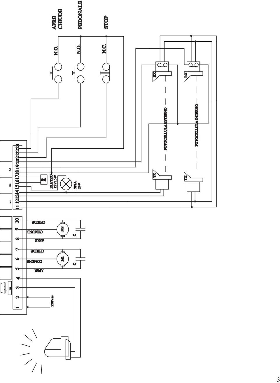
5 The D755M panel features an electronic photocell control system which switches the external photocell transmitter on and off thereby causing the control unit microprocessor to check whether the relay switches correctly. If this does not happen, the control unit is automatically blocked MICROPROCESSOR-CONTROL LOGIC SELF-DIAGNOSIS s LINE INPUT FUSE BUILT-IN TORQUE LIMITING DEVICE ELECTRONIC STARTING CONTROL ELECTRONIC CONTROL OF SAFETY DEVICES PEDESTRIAN ENTRY FUNCTION BUILT-IN FLASHING LIGHT CIRCUIT RECEIVER BOARD CONNECTOR 5 TERMINAL BOARD CONNECTIONS English 1 2 Power input 220/230 Vac 50 Hz 3 4 Flashing light output 230 Vac 50 W max. The signal is already modulated for direct use. Flashing frequency increases slightly during closing M1 motor output single-phase 230 Vac 300 W max. Common = 6; opening phase = 5; closing phase = 7 Connect the capacitor between terminals 5 and 7. Motor set for pedestrian use M2 motor output single-phase 230 Vac, 300 W max. Common = 9; opening phase = 8; closing phase = 10 Connect the capacitor between terminals 8 and Vac, 10 W output for powering photocells, external receivers, etc Vac output for powering the external TX photocell. For checking safety systems. (only connect the external TX photocell) Vac, 3W output for gate open indicator. The indicator lights up when the gate is wide open Vac, 15 W output for electric lock PHOTOCELL OR SAFETY DEVICE input INSIDE the gate (Normally Closed contact); 18 = COMMON. When these devices trigger during the opening phase, they temporarily stop the gate until the obstacle has been removed; during the closing phase they stop the gate and then totally open it again PHOTOCELL OR SAFETY DEVICE input OUTSIDE the gate (Normally Closed contact); 18 = COMMON. Then these devices trigger during the closing phase, they stop the gate and then totally open it again. N.B. the external photocell must always be connected (term power input term n.c. contact) as it is used to check the safety system; without this connection, therefore, the control unit will not power the actuators. To disable the safety system check move dip switch n 5 to OFF STOP button input (Normally Closed contact); this stops the gate. The gate opens after the following command. 18 = COMMON PEDESTRIAN pushbutton input (Normally Open contact); this is similar to the OPEN/CLOSE pushbutton, but only for the wing associated with the M1 motor which is used to control pedestrian traffic. 18 = COMMON OPEN-CLOSE pushbutton input (Normally Open contact); for operating instructions, please refer to dip-switch nos. 2 and 3 18 = COMMON Aerial input, 24 SIGNAL, 25 SHIELD

6 RADIO CHANNEL output. LOGIC ADJUSTMENTS (TRIMMER) T.L. Work time adjustment from 5 to 80 seconds. T.C.A. Automatic closing time adjustment from 2 to 130 seconds. (see dip-switch n 1) RIT. 2nd wing closing delay adjustment from 2 to 30 seconds. PROGRAMMING DIP SWITCHES N 1 Automatic closing disable: OFF: automatic closing disabled ON: automatic closing time (adjust with the T.C.A. trimmer) N 2 2 or 4 step operation: OFF: in the same conditions, the same command sequence causes the gate to OPEN STOP CLOSE STOP OPEN STOP, etc. (step by step function) ON: with automatic closing enabled, a sequence of open - close commands causes the gate to OPEN-CLOSE-OPEN-CLOSE, etc. N 3 No reverse: OFF: the gate ignores the close command while it is opening. ON: the gate behaves according to the position of dip-switch n 2 N 4 Clock function: OFF: a timer can be connected to the open-close pushbutton in order to keep the gate open at certain times during the day, after which it reverts to automatic closing. ON: the open-close pushbotton works in the standard mode. N 5 Pre-flashing disable: OFF: the light starts flashing when the automation is powered. ON: the light starts flashing a few seconds before the automation is powered and the photocells are checked. POWER ADJUSTMENT Power is adjusted by means of a four-position selector ranging from 1 (minimum power) to 4 (maximum power). This selector adjusts operator force directly from the control unit. SELF-DIAGNOSIS S The green s indicate the presence of normally closed contacts and are therefore always on unless there are system faults. The red s indicate normally open contacts and therefore only light up when they are used (except for 1 which indicates that the system is powered). DL1red = indicates the board is powered DL2red = indicates the OPEN CLOSE command is working DL3red = indicates the PEDESTRIAN command is working DL4green = indicates the STOP command is working DL5green = indicates the external photocell input is working DL6green = indicates the internal photocell input is working 6
 ON: with automatic closing enabled, a sequence of open - close commands causes the gate to OPEN-CLOSE-OPEN-CLOSE, etc.")
F4 PLUS. control MPS 120 - MPS 120E - MPS 160 - MPS 160E - MPS 240 - MPS 240E YES YES. 1 4 inputs Trimmers and DIP-switches YES
 CONTROL control F4 PLUS Anticrushing safety device To find out about the other functions, see the table on page 02 or 2 at 3W (maximum 700W) 220 TOP29 TOP39 TOP44 FLOOR80 BL230 ART5000 PASS220 PASS820
3PH2 or 3PHE 3 Phase Control Board
 3PH2 or 3PHE 3 Phase Control Board The 3-Phase Control Board is used to control automatic doors or gates that operate with 3-Phase or high current single-phase motors in high usage residential and commercial
455 D Control Board. FAAC International Inc. West Coast Operations 357 South Acacia Avenue Unit 357 Fullerton, CA 92831 Tel.
 455 D Control Board FAAC International Inc. Headquarter & East Coast Operations 55 Sunbeam Road Suites 9 Jacksonville, FL 57 Tel. 866 95 www.faacusa.com FAAC International Inc. West Coast Operations 57
We are pleased to inform you that the new FAAC B604 barrier is now available.
 Circular to DISTRIBUTORS and PARTNERS Zola Predosa, 16 January 2008 RE: NEW ELECTRO-MECHANICAL BARRIER 24V B604 We are pleased to inform you that the new FAAC B604 barrier is now available. It is an absolute
Contact Center CC-165 INSTALLATION & USER'S GUIDE
 Contact Center CC-165 INSTALLATION & USER'S GUIDE Table of Contents Introduction... 2 Specifications... 2 J4 Host Communications... 2 J5 and J12 (upper board)... 3 J6, J13, and 14 Input Connections...
FSLIMRF05-10 - 15-20 - 25
 1. INTRODUCTION FSLIMRF is a fully wireless, battery-powered infrared beam barrier for the protection of doors and windows with alarm radio transmission. The barrier is made up of two aluminium sections
AUTOMATIC TRANSFER SWITCH CONTROL UNIT OPERATOR S MANUAL
 ATS-220 AUTOMATIC TRANSFER SWITCH CONTROL UNIT OPERATOR S MANUAL For Use in 208 to 240 Volts Single and 3 Phase ATS Systems With 110Volt AC or DC Control Motors and selenoids 4501 NW 27 ave Miami FL 33142
SLIDING GATE OPERATORS
 SLIDING GATE OPERATORS INSTALLATION MANUAL CE GENERAL SAFETY If correctly installed and used, this automation device satisfies the required safety level standards.however, it is advisable to observe some
Safety Manual BT50(T) Safety relay / Expansion relay
 Safety relay / Expansion relay") Safety Manual BT50(T) Safety relay / Expansion relay ABB Jokab Safety Varlabergsvägen 11, SE-434 39, Sweden www.abb.com/jokabsafety Read and understand this document Please read and understand this document
Safety Manual BT50(T) Safety relay / Expansion relay ABB Jokab Safety Varlabergsvägen 11, SE-434 39, Sweden www.abb.com/jokabsafety Read and understand this document Please read and understand this document
SECTION 13XXX CONTROL DESCRIPTION (DICP Models 02-412NC, 412, 622, 826, 1030)
") PART 1 - GENERAL SECTION 13XXX CONTROL DESCRIPTION (DICP Models 02-412NC, 412, 622, 826, 1030) 1.01 SUMMARY This section describes the operation and control of a drip irrigation system. The major components
PART 1 - GENERAL SECTION 13XXX CONTROL DESCRIPTION (DICP Models 02-412NC, 412, 622, 826, 1030) 1.01 SUMMARY This section describes the operation and control of a drip irrigation system. The major components
Impulse G+/VG+ Series 3, 24 VDC Interface Card Terminal Designations
 Impulse G+/VG+ Series 3, 24 VDC Interface Card Terminal Designations Addendum to: IMPULSE G+ Series 3 Manual (140-10258) IMPULSE VG+ Series 3 Manual (140-10257) This addendum should be used when a 24VDC
SYSTEM 7000 IRIS+ USER MANUAL
 SYSTEM 7000 IRIS+ USER MANUAL Table of Contents Section Page No 1. INTRODUCTION... 3 2. THE DISPLAY... 3 3. TRANSMITTERS... 6 4. MESSAGE PAGER SYSTEM... 7 2 1. Introduction 1.1 The IRIS+ is a radio based
"($!$* -44 5 6 7.89 .#/ @9019 =3 5.# 19 = 77##.#2 19 79A951 88 "#$%!&#$'$()(!* "!$& %$!$*%!&& +", !"#$$"!"" %&!'""$&(&! )*""! %$"'""+,($" -. *""!
(!* !$& %$!$*%!&& +, !#$$! %&!'$&(&! )*! %$'+,($ -. *!") -.#/ @9019 =3 5.# 19 = 77##.#2 19 79A951 88!"#$$"!"" %&!'""$&(&! )*""! %$"'""+,($" -. *""!! /01 234#55 65571 50087( *""!! *5571 *579$+):#;$+#" *579#-;#-( *5791 1' 971 1' 951 1' 1 "#?=" 3 08!08&1@@
-.#/ @9019 =3 5.# 19 = 77##.#2 19 79A951 88!"#$$"!"" %&!'""$&(&! )*""! %$"'""+,($" -. *""!! /01 234#55 65571 50087( *""!! *5571 *579$+):#;$+#" *579#-;#-( *5791 1' 971 1' 951 1' 1 "#?=" 3 08!08&1@@
A.1. a Division of Pittway Corporation. Documento: M-010.1-MGAS-ENG. Edizione: 01/1997 Rev.:
 Documento: M-010.1-MGAS-ENG Edizione: 01/1997 Rev.: A.1 a Division of Pittway Corporation FRONT PANEL & VISUAL INDICATIONS GENERAL TROUBLE GENERAL PROGRAMMING IN PROGRESS ENABLE/ALARM/TROUBLE (ZONE 1 ALARM
Digital Fundamentals
 igital Fundamentals with PL Programming Floyd Chapter 9 Floyd, igital Fundamentals, 10 th ed, Upper Saddle River, NJ 07458. All Rights Reserved Summary Latches (biestables) A latch is a temporary storage
INSTALLATION GUIDE. Card Reader & Controller with KIM Swipe Reader for Solitaire 850 / 950 / 850L Learnlok PK2930
 INSTALLATION GUIDE Card Reader & Controller with KIM Swipe Reader for Solitaire 850 / 950 / 850L Learnlok PK2930 Card Reader and Controller Model 3.5 with KIM Swipe Reader Table of Contents 1. Features..................................
535T Window Automation System
 535T Window Automation System Installation Guide NOTE: This product is intended for installation by a professional installer only! Any attempt to install this product by any person other than a trained
SUBCHAPTER A. AUTOMOBILE INSURANCE DIVISION 3. MISCELLANEOUS INTERPRETATIONS 28 TAC 5.204
 Part I. Texas Department of Insurance Page 1 of 10 SUBCHAPTER A. AUTOMOBILE INSURANCE DIVISION 3. MISCELLANEOUS INTERPRETATIONS 28 TAC 5.204 1. INTRODUCTION. The commissioner of insurance adopts amendments
Controller Automation, Model II+
 Controller Automation Page 2 of 2 Automation with the RADAK II+ power controller II+ I/O Points: Inputs 5 Programmable Digital inputs 2 Dedicated digital inputs (Channel select and External SCR control
500r+ Installation and User Guide
 500r+ Installation and User Guide Compatible Equipment 502rUK-50 Watch/Pendant PA. 509rUK-50 Smoke Detector 515rUK-00 10 metre passive infra red movement detector. 525rUK-00 Remote Set/Unset (Full and
Quick Installation Guide TK-RP08. H/W: v1.0r
 Quick Installation Guide TK-RP08 H/W: v1.0r Table of of Contents Contents... 1. Before You Start... 2. How to Install... 3. Operation and Configuration... 1 1 2 5 Troubleshooting... 7 Version 04.10.2008
SECTION 13850 DETECTION AND ALARM
 SECTION 13850 DETECTION AND ALARM PART 1 GENERAL 1.01 SUMMARY A. Section Includes 1. Control Panel 2 Associated Equipment B. Products Installed But Not Supplied Under This Section 1. Section 16140 - Wiring
EC DECLARATION OF CONFORMITY FOR MACHINES
 EC DECLARATION OF CONFORMITY FOR MACHINES (DIRECTIVE 98/37/EC) Manufacturer: Address: Declares that: FAAC S.p.A. Via Benini, 1-40069 Zola Predosa BOLOGNA - ITALY 770 mod. operator is built to be integrated
ZC-24DO CANopen I/O Module: 24 Digital Outputs
 Z-PC Line EN ZC-24DO CANopen I/O Module: 24 Digital Outputs Installation Manual Contents: - General Specifications - Technical Specifications - Installation Rules - Electrical connections - DIP-switches
How To Control A Car Alarm On A Car With A Remote Control System
 MODEL CA100 REMOTE CONTROL AUTO ALARM SYSTEM INSTALLATION & OPERATION INSTRUCTIONS WIRING DIAGRAM Black Antenna Wire 6 Pin 6 Pin Mini Connector Valet Switch Blue LED Indicator Blue Wire: (-) 200mA Unlock
NELSON VOLTAGE MONITOR INSTALLATION & PROGRAMMING MANUAL
 NELSON VOLTAGE MONITOR INSTALLATION & PROGRAMMING MANUAL CONTENTS GENERAL INFORMATION...3 INSTALLATION...3 FIELD WIRING...4 PROGRAMMING...4 Circuit Monitor Options...5 Power Frequency...5 Alarm Silence
English AUTOMATION SYSTEMS FOR SLIDING GATES. Operating and installation instructions SLIDE SERIES
 English AUTOMATION SYSTEMS FOR SLIDING GATES Operating and installation instructions SLIDE SERIES v.0 Rev /202 INDEX ) General Safety Regulations... pág. 0 2) Description... pág. 02 3) Technical Specifications...
Car Alarm Series 2 B 2 Buttons
 Car Alarm Series 2 B 2 Buttons G22 SE (External - Shock Sensor) Version 3 Software 67 Plus www.geniuscaralarm.com 21 CAR ALARM GENIUS Series 2B 2 Buttons - G22 Se (External Shock Sensor) Module controlled
Operational Overview and Controls Guide. Two or Three Pump IronHeart Lite with Variable Frequency Drives
 DOCUMENT: ECSEQ6-0 EFFECTIVE: 09/23/10 SUPERSEDES: Operational Overview and Controls Guide Two or Three Pump IronHeart Lite with Variable Frequency Drives 6700 Best Friend Road. Norcross, GA 30071. (770)
WD-AMX Water Detection Controllers
 Page 1 of 5 WD-AMX Water Detection Controllers Features: Benefit: LED Status of leak status VFC output Audible alarm Auto or manual reset alarm output Uses an isolated AC signal which prevents oxidation
PS 155 WIRELESS INTERCOM USER MANUAL
 PS 155 INTERFACE TO SIMPLEX WIRELESS INTERCOM USER MANUAL Issue 2011 ASL Intercom BV DESIGNED AND MANUFACTURED BY: ASL INTERCOM BV ZONNEBAAN 42 3542 EG UTRECHT THE NETHERLANDS PHONE: +31 (0)30 2411901
ZME_05459 Wall Blind Control Set for Busch-Jaeger DURO 2000 Firmware Version : 1.8
 ZME_05459 Wall Blind Control Set for Busch-Jaeger DURO 2000 Firmware Version : 1.8 Quick Start A This device is a Z-Wave Actuator. Triple click one of the buttons on the device will include the device.
HPN Product Tools. Copyright 2012 Hewlett-Packard Development Company, L.P. The information contained herein is subject to change without notice.
 HPN Product Tools Requerimiento: Conozco el numero de parte (3Com,H3C,Procurve) Solución : El lookup Tool 1 Permite convertir el número de parte de un equipo proveniente de 3Com, H3C o Procurve para obtener
ALARM ANNUNCIATOR ME - 3010 INSTRUCTION MANUAL
 ALARM ANNUNCIATOR ME - 3010 INSTRUCTION MANUAL INTRODUCTION... 2.. TECHNICAL DATA... 3 ACCESSORIES... 5. INSTALLATION... 7 OPERATION... 12. TECHNICAL INFORMATION... 13 MAINTENANCE... 14. CONFIGURATIONS...
GSM Gate Opener GSM Remote Switch RTU5015 User Manual
 GSM Gate, Barrier, Shutter, Garage Door and Door opener Open gate or garage door with a FREE call from your mobile phone! Remote switching machines with a FREE call from your mobile phone! GSM Gate Opener
Verbos modales. In this class we look at modal verbs, which can be a tricky feature of English grammar.
 Verbos modales In this class we look at modal verbs, which can be a tricky feature of English grammar. We use Modal verbs in English to show: Probability,Possibility, Capability, Permission, ObligaCon,
3FBD DC Motor Drive User Manual
 3FBD DC Motor Drive User Manual Via I. Alpi 6 - zona industriale - Lonato (BS) Tel. +39 30 9913491 r.a. Fax. +39 30 9913504 http://www.re-elettronica.it info@re-elettronica.it Pag. 1 Index Index... pag.1
Short Range Wireless Switch System Handheld 8 Installation and Operations Guide
 Phone: (866) 701-1146 Fax: (425) 216-7558 www.remotecontroltech.com Short Range Wireless Switch System Handheld 8 Installation and Operations Guide Introduction... 2 Before Installation... 2 Receiver Installation...
Electronic Control Devices The European Product Catalogue 2007
 FX14 Field Controller (1/4) FX14 Field Controller The FX14 is an equipment field controller in the Facility Explorer range of products. The controller is designed specifically for commercial Heating, Ventilating,
Chapter 9 N.C. C. N.O. Single-Pole Double-Throw
 rather than providing multiple choices. The sensor modules used may only be suitable for use with the matching controller so it is wise to read the specifications to make sure the unit suits your application.
INTRIC E. D811285 13-11-00 Vers. 02 SELF-LEARNING ROLLING-CODE EXTERNAL RECEIVER
 D811285 13-11-00 Vers. 02 SELF-LEARNING ROLLING-CODE EXTERNAL RECEIVER 360 1) GENERAL OUTLINE Thank you for buying this product, our company is sure that you will be more than satisfied with the performance
Inwall 4 Input / 4 Output Module
 Inwall 4 Input / 4 Output Module IO44C02KNX Product Handbook Product: Inwall 4 Input / 4 Output Module Order Code: IO44C02KNX 1/27 INDEX 1. General Introduction... 3 2. Technical data... 3 2.1 Wiring Diagram...
Master Time Clock MTC-200 MTC-400 MTC-600. Users Manual
 Master Time Clock MTC-200 MTC-400 MTC-600 Users Manual Toll Free (888)713-0373 Phone (972)987-4408 FAX (877)720-9291 www.midwest-time.com sales@midwest-time.com TABLE OF CONTENTS TOPIC PAGE GENERAL DESCRIPTION
SUBCHAPTER A. AUTOMOBILE INSURANCE DIVISION 3. MISCELLANEOUS INTERPRETATIONS 28 TAC 5.204
 Part I. Texas Department of Insurance Page 1 of 11 SUBCHAPTER A. AUTOMOBILE INSURANCE DIVISION 3. MISCELLANEOUS INTERPRETATIONS 28 TAC 5.204 1. INTRODUCTION. The Texas Department of Insurance proposes
1 All safety instructions, warnings and operating instructions must be read first.
 ONYX USER MANUAL 2 Dateq ONYX Manual Safety instructions EN Safety instructions 1 All safety instructions, warnings and operating instructions must be read first. 2 All warnings on the equipment must be
Computer Controlled Generating Stations Control and Regulation Simulator, with SCADA SCE
 Technical Teaching Equipment Computer Controlled Generating Stations Control and Regulation Simulator, with SCADA SCE EDIBON SCADA System Teaching Technique used 4 5 2 Data Acquisition Board Cables and
UNIVERSIDAD FRANCISCO DE PAULA SANTANDER DOMINIOS DE COLISION, SEGMENTACION Y VLAN. Academia Local. Ing. José Martín Calixto Cely
 UNIVERSIDAD FRANCISCO DE PAULA SANTANDER DOMINIOS DE COLISION, SEGMENTACION Y VLAN Academia Local Ing. José Martín Calixto Cely COLLISIONS AND COLLISION DOMAINS Types of Networks Shared media environment
Switch Actuator, 8-fold, 10 A, MDRC AT/S 8.10.1, GH Q631 0075 R0111
 , GH Q631 0075 R0111 The 8-fold switch actuator is a DIN rail mounted device for insertion in the distribution board. It is connected to the EIB via a bus terminal. In the event of bus voltage failure,
OPL BASIC. Dosing System for Professional Laundry machines. Contents
 OPL BASIC Dosing System for Professional Laundry machines Contents 1 Getting Started. Page 2 2 Installation. Page 4 3 Set Up & Operation. Page 8 4 Maintenance & Accessories. Page 10 5 Troubleshooting Page
GSM Gate Opener GSM Remote Switch RTU5015. User Manual. Ver 1.3 Date Issued: 2010-08-18. All rights reserved by King Pigeon Hi-Tech. Co., Ltd.
 GSM Gate, Barrier, Shutter, Garage Door and Door opener Open gate or garage door with a FREE call from your mobile phone! Remote switching machines with a FREE call from your mobile phone! GSM Gate Opener
Button 1 Button 2. Button 3 Button 4. Programmed Remote Transmitter. Button Function Condition
 WWW.STELLAR.COM ST9000 SECURITY SYSTEM Button Function Condition 1 a. Arm and lock doors b. Car finder with sound c. Temporary stop alarm from sounding d. Remote lock doors 1 for 2 sec. Panic Anytime a.
Software Manual RS232 Laser Merge Module. Document # SU-256521-09 Rev A
 Laser Merge Module Document # SU-256521-09 Rev A The information presented in this document is proprietary to Spectral Applied Research Inc. and cannot be used for any purpose other than that for which
Electric Landing Gear controllers and sequencer LGC12 / LGC 13C
 Electric Landing Gear controllers and sequencer LGC12 / LGC 13C Users Guide. Torrent d en Puig, 31. 08358, Arenys de Munt, Barcelona,Catalonia,Spain E-mail: info@xicoy.com. Fax: +34 933 969 743 web: www.xicoy.com
Descriptive Technical Documentation. DTD no. 521-7135
 Descriptive Technical Documentation - Model-dependent - DTD no. 521-7135 Model(s): PT 7135 C, PT 7136, PT 5135 C, PT 5136 14.10.2005, DE_en This information should not be duplicated or passed on without
AC/DC Power Supply Reference Design. Advanced SMPS Applications using the dspic DSC SMPS Family
 AC/DC Power Supply Reference Design Advanced SMPS Applications using the dspic DSC SMPS Family dspic30f SMPS Family Excellent for Digital Power Conversion Internal hi-res PWM Internal high speed ADC Internal
Operating instructions Diffuse reflection sensor. OJ50xx 701396 / 01 07 / 2004
 Operating instructions Diffuse reflection sensor OJ50xx 7096 / 0 07 / 004 Contents Preliminary note. Symbols used Function and features Installation. Installation of the supplied mounting fixture 4 4 Electrical
Conventional Fire Detection and Extinguishant Control System Specification
 Conventional Fire Detection and Extinguishant Control System Specification Page 1 of 9 Scope Furnish a complete 24VDC Conventional, electrically supervised, combined fire detection and extinguishant release
TECHNICAL BULLETIN. Wiring Diagrams. TPI Wiring. TB1010-04 Rev. March 4, 2013 Page 1 of 5. Switch Settings 3 PHASE POWER SUPPLY 3 PHASE POWER SUPPLY
 Page 1 of 5 Wiring and Programming of the TPI (Turbine Pump Interface) with an FEPetro SCIII (3-Phase Smart Controller) Overview The STP-SCIII 3-Phase Smart Controller can be controlled by the INCON TPI
LINIO COLOMBIA. Starting-Up & Leading E-Commerce. www.linio.com.co. Luca Ranaldi, CEO. Pedro Freire, VP Marketing and Business Development
 LINIO COLOMBIA Starting-Up & Leading E-Commerce Luca Ranaldi, CEO Pedro Freire, VP Marketing and Business Development 22 de Agosto 2013 www.linio.com.co QUÉ ES LINIO? Linio es la tienda online #1 en Colombia
Single-phase (220...240 V) voltage monitoring: Undervoltage Overvoltage Window mode (overvoltage + undervoltage) Voltage fault memory selectable
 voltage monitoring: Undervoltage Overvoltage Window mode (overvoltage + undervoltage) Voltage fault memory selectable") Features 70.11 70.31 70.41 Electronic voltage monitoring relays for single and three-phase applications Multifunctional types, providing the flexibility of monitoring Undervoltage, Overvoltage, Window
Features 70.11 70.31 70.41 Electronic voltage monitoring relays for single and three-phase applications Multifunctional types, providing the flexibility of monitoring Undervoltage, Overvoltage, Window
Instruction Manual for Operating Panel 301 and 302
 Instruction Manual for Operating Panel 301 and 30 Edition: 1/006 Edition: 1/006 Contents 1 Introduction and Overview........................ 5 1.1 Panel 301 Controls........................................
How To Use A Power Supply On A Powerline 2.2 (Ai)
") KNX/EIB Product documentation Issue: 05.08.2010 629x1220 Push button sensor 3 comfort 1-gang Push button sensor 3 comfort 2-gang (1+1) Push button sensor 3 comfort 3-gang Push button sensor 3 comfort 4-gang
KNX/EIB Product documentation Issue: 05.08.2010 629x1220 Push button sensor 3 comfort 1-gang Push button sensor 3 comfort 2-gang (1+1) Push button sensor 3 comfort 3-gang Push button sensor 3 comfort 4-gang
543-0032-00, 943-0032-00. User s Manual
 543-0032-00, 943-0032-00 User s Manual 1 Comfort Alert Diagnostics Faster Service And Improved Accuracy The Comfort Alert diagnostics module is a breakthrough innovation for troubleshooting heat pump and
Safety automation solutions
 Operating principle, characteristics Preventa safety s types XPS AV,, For and switch monitoring Operating principle Safety s XPS AV, and are used for monitoring circuits conforming to standards EN/ISO
CLASS D POWER AMPLIFIERS
 2015 CLASS D POWER AMPLIFIERS ETAPAS DE POTENCIA/ POWER AMPLIFIERS CLASS D 3rd. GENERATION / DSP MUSICSON ha desarrollado una gama completa de etapas de potencia de clase D de tercera generación con fuente
How to read this guide
 How to read this guide The following shows the symbols used in this Quick start guide with descriptions and examples. Symbol Description Example P oint Reference Caution [ ] This symbol explains information
CR9971 2 Band Auto Set Dual Alarm Clock Radio ROBERTS. Sound for Generations. Please read this manual before use
 ROBERTS Sound for Generations CR9971 2 Band Auto Set Dual Alarm Clock Radio Please read this manual before use Contents Contents... 1 Controls...2-5 Switching on... 6 Setting the time manually... 6 Setting
WIRING HARNESS FOR AS635P4. BLUE PLUG RED, BLUE, BLACK, WHITE - Plug in dual stage sensor harness
 WIRING HARNESS FOR AS635P4 ANTENNA NOT USED 5 PIN WHITE PLUG 2 PIN WHITE PLUG GREEN - PARKING BRAKE INPUT (-) BLUE - NOT USED 3 PIN BLUE PLUG RED, BLUE, BLACK, WHITE - Plug in dual stage sensor harness
CONTENTS. 1. CE DECLARATION OF CONFORMITY FOR MACHINES pag.11. 2. DESCRIPTION pag.12. 3. TECHNICAL SPECIFICATIONS pag.13. 4. INSTALLATION pag.
 CONTENTS 1. CE DECLARATION OF CONFORMITY FOR MACHINES pag.11. DESCRIPTION pag.1 3. TECHNICAL SPECIFICATIONS pag.13 4. INSTALLATION pag.13 5. TESTING THE AUTOMATED SYSTEM pag.19 6. MANUAL OPERATION pag.19
MODULE FOR AUTOMATIC CONTROL OF AN ELECTRICALLY OPERATED VALVE
 MODULE FOR AUTOMATIC CONTROL OF AN ELECTRICALLY OPERATED VALVE A module for valve control is a necessary component between the final control element the valve with its actuator and the computer system
CMD-9000 COMMANDER SERIES REMOTE CONTROL ENTRY SYSTEM
 CMD-9000 COMMANDER SERIES REMOTE CONTROL ENTRY SYSTEM INTRODUCTION Thank you for purchasing the CMD-9000 Commander from Dakota Digital. This, along with many other products that Dakota Digital has to offer,
Backup Scanner Module
 Backup Scanner Module Catalog Number 1747-BSN Installation Instructions 2 Backup Scanner Module Important User Information Because of the variety of uses for the products described in this publication,
ANTI-THEFT SYSTEM. 1995 Volvo 850 DESCRIPTION & OPERATION BASIC ALARM. 1995-96 ACCESSORIES & EQUIPMENT Volvo Anti-Theft Systems
 ANTI-THEFT SYSTEM 1995 Volvo 850 1995-96 ACCESSORIES & EQUIPMENT Volvo Anti-Theft Systems 850 DESCRIPTION & OPERATION WARNING: Deactivate air bag system before performing any service operation. For 1995
LOXONE 12 Channel Amplifier
 LOXONE 12 Channel Amplifier Item no.: 200110 Thank you for purchasing the Loxone Twelve Channel Amplifier. The versatility of the Amplifier makes it the perfect choice for almost every type of custom multi-room
Quick Installation Guide TK-209K TK-409K
 Quick Installation Guide TK-209K TK-409K Table of of Contents Contents English... 1. Before You Start... 2. How to Connect... 3. Operation... 1 1 2 4 Troubleshooting... 5 Version 03.16.2007 1. Before You
ABB Drives. User s Manual. Pulse Encoder Interface Module RTAC-01
 ABB Drives User s Manual Pulse Encoder Interface Module RTAC-0 Pulse Encoder Interface Module RTAC-0 User s Manual 3AFE 64486853 REV A EN EFFECTIVE:.5.00 00 ABB Oy. All Rights Reserved. Safety instructions
Plena Weekly Timer. Installation and User Instructions PLN-6TMW
 Plena Weekly Timer en Installation and User Instructions PLN-6TMW Plena Weekly Timer Installation and User Instructions Important Safeguards en 2 Important safeguards Prior to installing or operating this
Electrical data Nominal voltage AC/DC 24 V Nominal voltage frequency
 echnical data sheet NV24A--RE Communicative globe valve actuator for 2-way and 3-way globe valves Actuating force 1000 N Nominal voltage AC/DC 24 V Control Modulating DC (0)2...10 V Variable Nominal stroke
HAM841K ALARM CONTROL PANEL FOR COMMERCIAL AND RESIDENTIAL SECURITY SYSTEMS
 ALARM CONTROL PANEL FOR COMMERCIAL AND RESIDENTIAL SECURITY SYSTEMS USER MANUAL USER MANUAL ALARM CONTROL PANEL FOR COMMERCIAL AND RESIDENTIAL SECURITY SYSTEMS INTRODUCTION The (HA-841K) is a complete
ABB i-bus KNX Switch Actuator, x-fold, 16/20 A, MDRC SA/S x.16.6.1, 2CDG 110 1xx R0011
 , 2CDG 110 1xx R0011 SA/S 8.16.6.1 2CDC 071 006 S0010 The 16/20 A Switch actuators are modular installation devices in Pro M Design for installation in the distribution board. The devices are especially
Installation & User Manual Radio Remote rev1.0.3
 EN Installation & User Manual Radio Remote rev1.0.3 RC-20E RC-21E RC-22E RC-23E SLEIPNER MOTOR AS P.O. Box 519 N-1612 Fredrikstad Norway Tel: +47 69 30 00 60 Fax: +47 69 30 00 70 www.side-power.com sidepower@sleipner.no
AMI MARINE (UK) LTD BRIDGE NAVIGATIONAL WATCH ALARM SYSTEM (BNWAS) Operation Manual KW810
 LTD BRIDGE NAVIGATIONAL WATCH ALARM SYSTEM (BNWAS) Operation Manual KW810") AMI MARINE (UK) LTD BRIDGE NAVIGATIONAL WATCH ALARM SYSTEM (BNWAS) Operation Manual KW810 This Manual and the information contained therein is the property of AMI Marine (UK) Ltd. It must not be reproduced
AMI MARINE (UK) LTD BRIDGE NAVIGATIONAL WATCH ALARM SYSTEM (BNWAS) Operation Manual KW810 This Manual and the information contained therein is the property of AMI Marine (UK) Ltd. It must not be reproduced
Wiring Instructions and Operating Manual 12 POINT ULTRABEAM REMOTE MONITORING SYSTEM
 Wiring Instructions and Operating Manual 12 POINT ULTRABEAM REMOTE MONITORING SYSTEM Hycontrol Limited, Larchwood House, Orchard Street, Redditch, Worcestershire, B98 7DP, UK. Tel: +44 (0)1527 406800 Fax:
Product Description Full Voltage Starting Electric Fire Pump Controllers FTA1000
 Product Description Full Voltage Starting Electric Fire Pump Controllers FTA1000 Description Firetrol FTA1000 Full Voltage Fire Pump Controllers are intended for use with electric motor driven fi re pumps
TIR 60-120. D811162 04-04-02 Vers. 04 AUTOMATION FOR SPRING OVERHEAD DOORS
 TIR 60-120 D811162 04-04-02 Vers. 04 AUTOMATION FOR SPRING OVERHEAD DOORS Thank you for buying this product, our company is sure that you will be more than satisfied with the product s performance. The
CM705B - Universal Expander Module CM707B - Plug On Zone Expander Security Systems
 CM705B - Universal Expander Module CM707B - Plug On Zone Expander Security Systems EN Security System CM705B CM705B - Universal Expander Module The CM705B universal expander provides a cost effective way
 ABLOY DA60 SWING DOOR OPERATOR Installation and commissioning manual Abloy Oy An ASSA ABLOY Group company APPROVALS / STANDARDS Low Voltage directive 7//EEC as amended by the directive 9/68/EEC EMC directive
TAC1 Telephone Entry System Installation and Programming Manual
 TAC Telephone Entry System 4 7 3 6 8 9 Installation and Programming Manual The Chamberlain Group 84 Larch Ave. Elmhurst, IL 66-96 www.liftmaster.com TABLE OF CONTENTS SPECIFICATIONS 3 Cable Requirements
1R / 4-BUTTON SERIES
 Button 1 1R / 4-BUTTON SERIES VEHICLE SECURITY SYSTEM Standard Features: Two 4-Button Remote Transmitters Status indicator (LED) Valet / override switch Multi-tone siren Dual stage impact detector Remote
Electronic Power Control
 Service. Self-Study Programme 210 Electronic Power Control Design and Function With the Electronic Power Control system, the throttle valve is actuated only by an electric motor. This eliminates the need
Electronic Control Devices The European Product Catalogue 2007
 FX07 Field Controller (1/4) FX07 Field Controller Display Model Dimensions in mm (inches) The FX07 is a terminal unit controller in the Facility Explorer range of products. The controller is designed specifically
INSTALLATION MANUAL VEHICLE SECURITY SYSTEM CE-SS200
 INSTALLATION MANUAL VEHICLE SECURITY SYSTEM CE-SS200 FUSION CULTURE TABLE OF CONTENTS There s no point doing something if no one notices. We ve always believed the way to make things happen is by getting
OPEN PARK. Automatic Number Plate Recognition that works worldwide including Egypt Number plates
 Automatic Number Plate Recognition that works worldwide including Egypt Number plates Free subscription lane, ticket dispenser for nonmembers, ticket readers, e- payment with NFC OPEN PARK INTEGRATED PARKING
EL-Skyport Universal Receiver Speed Triggers flashes or cameras and receives - transmits basic information to the computer remote control.
 EL-Skyport speed EN EL-Skyport Speed EL-Skyport Speed System The EL-Skyport update includes new features and many improvements in compatibility and look. The ELS System provides flash triggering and the
PRO PLM Installation Instructions
 PRO PLM Installation Instructions PROFESSIONAL INSTALLATION STRONGLY RECOMMENDED Installation Precautions: Roll down window to avoid locking keys in vehicle during installation Avoid mounting components
Operating Instructions. UL325 Compliant Non-monitored
 IRB-325 Infrared Photocell UL325 Compliant Non-monitored Operating Instructions This product is an accessory or part of a system. Always read and follow the manufacturer s instructions for the equipment
Time functions. Functions of the relay. instabus EIB Application program description. September 2001. 12 A1 Binary 510D01
 September 2 2 A Binary 5D Product family: Product type: Manufacturer: Output Binary output, -fold Siemens Name: Load switch UP 5 Order no.: 5WG 5-2AB Functional description Using the application program
INSTALLATION MANUAL 3RP / 5RP 4-BUTTON SERIES VEHICLE SECURITY SYSTEMS
 3RP / 5RP 4-BUTTON SERIES VEHICLE SECURITY SYSTEMS INSTALLATION MANUAL Before you begin the installation Read the INSTRUCTIONS! Always use a multi-meter when verifying vehicle wiring. Before mounting the
Quick Installation Guide TK-204UK H/W: V1.0R
 Quick Installation Guide TK-204UK H/W: V1.0R English... 1. Before You Start... 2. How to Install... 3. Operation... 4. Using the KVM Utility... Specifications... Troubleshooting... 1 1 2 4 5 8 9 1. Before
Adding Pneumatic Preset Counter. Type 497. Continuously visible preset Integrated pneumatic reset 3 or 5-digit display Convenient button setting
 Adding Pneumatic Preset Counter Type 497 Continuously visible preset Integrated pneumatic reset 3 or 5-digit display Convenient button setting VARIABLE PILOT SIGNAL Using two pneumatic preset counters