ZyWALL USG Series. Application Notes. Unified Security Gateway. Version 4.10 Edition 1, 05/2014. Copyright 2014 ZyXEL Communications Corporation
|
|
|
- Frederick Wood
- 8 years ago
- Views:
Transcription
1 ZyWALL USG Series Unified Security Gateway Version 4.10 Edition 1, 05/2014 Application Notes Copyright 2014 ZyXEL Communications Corporation 0

2 ZyXEL USG Application Notes Table of Contents Scenario 1 Connecting your USG to the Internet Application Scenario Configuration Guide... 4 Scenario 2 WAN Load Balancing and Customized Usage of WAN Connection for Specific Traffic --Dual WAN setting Application Scenario Configuration Guide... 8 Scenario 3 How to configure NAT if you have Internet-facing public servers Application Scenario Configuration Guide Scenario 4 Secure site-to-site connections by using IPSec VPN IPv4 with IKEv2 / IPv Application Scenario Configuration Guide Scenario 5 Connect to USG by using IPSec IKEv2 in Windows Application Scenario Configuration Guide Scenario 6 GRE over IPSec VPN tunnel VPN fail over Application scenario Configuration Guide Scenario 7 - Deploying SSL VPN for Tele-workers to Access Company Resources SSL VPN with Apple Mac OSX Application Scenario Configuration Guide Scenario 8 Reserving Highest Bandwidth Management Priority for VoIP traffic Application Scenario Configuration Guide Scenario 9 - Reserving Highest Bandwidth Management Priority for a Superior User and Control Session per Host BWM Per IP or Per User Application Scenario Configuration Guide Scenario 10 - Using USG to Control Popular Applications APP patrol Application Scenario Configuration Guide

3 ZyXEL USG Application Notes Scenario 11 configure unified policy (firewall policy + UTM profile) Application Scenario Configuration Guide Scenario 12 Block HTTPs web site by Content Filter Application Scenario Configuration Guide Scenario 13: Single sign-on with USG and Windows platform Application Scenario Configuration Guide Scenario 14 WLAN Controller function on USG Application Scenario Configuration Guide Scenario 15 Device HA on the USG Application Scenario Configuration Guide

4 ZyXEL USG Application Notes Tutorial 1: How to Set Up Your Network Wizard Overview How to Configure Interfaces, Port Roles, and Zones How to Configure a Cellular Interface How to Set Up a Wireless LAN How to Set Up IPv6 Interfaces For Pure IPv6 Routing How to Set Up an IPv6 6to4 Tunnel How to Set Up an IPv6-in-IPv4 Tunnel Tutorial 2: Protecting Your Network Firewall User-aware Access Control Device and Service Registration Anti-Virus Policy Configuration IDP Profile Configuration ADP Profile Configuration Content Filter Profile Configuration Viewing Content Filter Reports Anti-Spam Policy Configuration Tutorial 3: Create Secure Connections Across the Internet IPSec VPN VPN Concentrator Example Hub-and-spoke IPSec VPN Without VPN Concentrator USG IPSec VPN Client Configuration Provisioning SSL VPN L2TP VPN with Android, ios, and Windows Tutorial 4: Managing Traffic How to Configure Bandwidth Management How to Configure a Trunk for WAN Load Balancing How to Use Multiple Static Public WAN IP Addresses for LAN-to-WAN Traffic How to Use Device HA to Backup Your USG How to Configure DNS Inbound Load Balancing How to Allow Public Access to a Web Server How to Manage Voice Traffic How to Limit Web Surfing and MSN to Specific People

5 ZyXEL USG Application Notes Scenario 1 Connecting your USG to the Internet 1.1 Application Scenario Nowadays, many Internet service providers offer an IPv6 environment. With an IPv6 feature enabled on the USG, it can assign an IPv6 address to clients and pass IPv6 traffic through IPv4 environment to access a remote IPv6 network. 1.2 Configuration Guide Network conditions: USG: WAN1: (Static PPPoE v4) Or WAN1: (Static) Goal to achieve: A USG will assign an IPv6 IP addresses to the clients, which are behind it, and the clients can access a remote IPv6 network by using the USG 6to4 tunnel. USG configuration Step 1: Configuration > System > IPv6 > Click Enable IPv6 4
 Goal to achieve: A USG will assign an IPv6 IP addresses to the clients, which are behind it, and the clients can access a remote IPv6 network by using the USG")
 Configuration > Interface > Ethernet > double-click LAN1 interface in IPv6 configuration.")
6 ZyXEL USG Application Notes Step 2: Setting the static IP on WAN1 Configuration > Interface > Ethernet > double-click on WAN1 interface and configure with static IP address Step 3: Setting IPv6 IP address on LAN1 (1) Configuration > Interface > Ethernet > double-click LAN1 interface in IPv6 configuration. 5
 Configuration > Interface > Ethernet")
 Check the IPv6 Router Advertisement Setting box and add the prefix in the Advertised Prefix Table. Step 4: Enable 6 to 4 tunnel. (1) Configuration > Interface>Tunnel > Click on the Add button. 6")
7 ZyXEL USG Application Notes (2) Convert WAN1 IP address to hexadecimal (Decimal) = 3b7c:a396(Hex). Fill-in 2002:3b7c:a396::1/128 in the prefix table as the LAN interface IPv6 address. (3) Check the IPv6 Router Advertisement Setting box and add the prefix in the Advertised Prefix Table. Step 4: Enable 6 to 4 tunnel. (1) Configuration > Interface>Tunnel > Click on the Add button. 6
 Check the IPv6 Router Advertisement Setting box and add the prefix in the Advertised Prefix")
 Check the Prefix in the 6tp4 tunnel Parameter.")
8 ZyXEL USG Application Notes (2) Select the 6to4 in that Tunnel Mode. (3) Check the Prefix in the 6tp4 tunnel Parameter. (4) Select the WAN1 interface as the gateway in the Gateway Setting. 7

9 ZyXEL USG Application Notes Scenario 2 WAN Load Balancing and Customized Usage of WAN Connection for Specific Traffic -- Dual WAN setting 2.1 Application Scenario The company has two WAN connections for sharing outbound internet traffic. WAN1 uses a static IP address, and WAN2 uses a PPPoE connection. Since WAN1 ISP is also the company s VoIP provider, the network administrator wants VoIP traffic primarily sent out over WAN1. In case WAN1 is down, the VoIP traffic can still go out over WAN2 PPPoE connection. The network administrator also wants HTTP traffic sent over WAN2 PPPoE connection primarily. In case WAN2 PPPoE is down, LAN users can still surf Internet over WAN1. For all other types of traffic, administrator needs the two WAN connections to share the outbound traffic load, performing load balancing. 2.2 Configuration Guide Goals to achieve: 1) VoIP traffic goes out primarily through WAN1. In case WAN1 is down, it will go out via WAN2 PPPoE connection. 2) HTTP traffic goes out primarily through WAN2 PPPoE connection. In case WAN2 PPPoE is down, it will go out via WAN1. 3) All other traffic goes out via WAN trunk performing Load Balancing with Least 8

10 ZyXEL USG Application Notes Load Balancing algorithm. USG configuration Step 1. Configure a PPPoE account on WAN2 interface. (1) Go to CONFIGURATION > Object > ISP Account, add a PPPoE account: (2) Go to CONFIGURATION > Network > Interface > PPP, add a new PPP interface, which is based on WAN 2 interface: 9

 Add WAN trunk for VoIP traffic Set WAN1 as Active mode, while setting WAN2_ppp as Passive mode. (2) Add WAN trunk for HTTP traffic Set WAN2_ppp as Active mode, while setting WAN1 as Passive mode.")
11 ZyXEL USG Application Notes Step 2. Go to CONFIGURATION > Network > Interface > Trunk. Add WAN Trunks. (1) Add WAN trunk for VoIP traffic Set WAN1 as Active mode, while setting WAN2_ppp as Passive mode. (2) Add WAN trunk for HTTP traffic Set WAN2_ppp as Active mode, while setting WAN1 as Passive mode. (3) Use SYSTEM_DEFAULT_WAN_TRUNK to perform load balancing for all other traffic. Step 3. Go to CONFIGURATION > Network > Routing > Policy Route, add policy 10
 Use SYSTEM_DEFAULT_WAN_TRUNK to perform load balancing for all other traffic. Step 3.")
 Add a policy route for VoIP traffic: Source: LAN1_subnet Destination: Any Service: SIP Next Hop: select the newly created WAN trunk WAN_Trunk_VoIP Please note that to make sure this policy route")
12 ZyXEL USG Application Notes routes for VoIP traffic and HTTP traffic. (1) Add a policy route for VoIP traffic: Source: LAN1_subnet Destination: Any Service: SIP Next Hop: select the newly created WAN trunk WAN_Trunk_VoIP Please note that to make sure this policy route applies to all VoIP traffic, including both the SIP signaling and RTP (voice data), we need to enable SIP ALG. Go to Configuration > Network > ALG, enable SIP ALG. (2) Add a policy route for HTTP traffic: Source: LAN1_subnet Destination: Any Service: HTTP Next Hop: Select the newly created WAN trunk WAN_Trunk_HTTP. 11


13 ZyXEL USG Application Notes (3) For all other traffic, use SYSTEM_DEFAULT_WAN_TRUNK to perform load balancing. Go to Configuration > Network > Interface > Trunk. Click on Show Advanced Settings. Make sure Default SNAT is enabled. Select SYSTEM_DEFAULT_WAN_TRUNK in Default Trunk Selection. 12

14 ZyXEL USG Application Notes Scenario 3 How to Configure NAT if you have Internet-facing Public Servers 3.1 Application Scenario It is a common practice to place company servers behind the USG s protection; while at the same time letting WAN side clients/servers access the intranet servers. To give an example, the company may have an internal FTP server, which needs to be accessible from the Internet as well. To fulfill this requirement, the user can configure a NAT mapping rule to forward the traffic from the Internet side to intranet side. This feature does not only ensure service availability, but also helps avoid exposing the server s real IP address from being attacked. 3.2 Configuration Guide Goal to achieve: User Tom can access the Internet FTP server by accessing the Internet-facing the WAN IP address. Network Conditions: USG-50: - WAN IP: FTP server IP: Configuration Step 1. Go to CONFIGURATION > Network > NAT to open the configuration screen. 13

 address - Fill-in the Mapped IP (Internal")
15 ZyXEL USG Application Notes Step 2. Click on the Add button to create a mapping rule. Step 3. In this page, the user needs to configure: - Rule s name - Select Virtual Server type to let USG-50 do packet forwarding - Fill-in the Original IP (WAN IP) address - Fill-in the Mapped IP (Internal FTP server IP) address - Select the service to be mapped (FTP); the ports will be selected automatically Step 4. Go to CONFIGURATION > Security Policy > Policy Control to open the firewall configuration screen. Here assume the user already assigned the WAN interface to WAN zone and LAN interface to LAN1 zone. Step 5. Click on the Add button to create a firewall rule to enable the FTP service to pass from WAN to LAN1. 14

 to be enabled -")
16 ZyXEL USG Application Notes Step 6. The user can create an address object for the internal FTP server for further configuration usage. Click on Create new Object for this function. Step 7. Configure the rule to: - Allow access from WAN to LAN1 - Source IP address is not specific - Destination IP address is the FTP server s address - Select FTP service (with port 20/21) to be enabled - Select the allow action for matched packets 15


17 ZyXEL USG Application Notes Step 8: Click on the OK button, you will see the rule in policy control. 16

18 ZyXEL USG Application Notes Scenario 4 Secure Site-to-site Connections using IPSec VPN IPv4 with IKEv2 / IPv6 4.1 Application Scenario IPv4 with IKEv2 We want to use IKEv2 to establish a VPN tunnel between the HQ and Branch Office. IPv6 (with IKEv2 only) ISP has changed the environment to IPv6. We applied for IPv6 address pool for internal use. So we have to change use the IPv6 address to establish an VPN tunnel between the USG. 4.2 Configuration Guide IPv4 Network Conditions: USG-40W with static WAN: - WAN IP: Local subnet: /24 17

19 ZyXEL USG Application Notes USG-40W with PPPOE WAN: - PPPOE IP: Local subnet: /24 IPSec VPN Conditions: Phase 1: Phase 2: IKE version: IKEv2 Active Protocol: ESP Authentication: Encapsulation Mode: Tunnel Local/Peer ID type: IPv / Any Encryption Algorithm: DES Encryption Algorithm: 3DES Authentication Algorithm: SHA1 Authentication Algorithm: MD5 Perfect Forward Secrecy: None Key Group: DH1 Goal to achieve: Establish an IPSec VPN tunnel between two USGs with the above configuration. Step 1. Go to CONFIGURATION > VPN > IPSec VPN > VPN Gateway to open the configuration screen. Step 2. Click on the Add button to add a VPN gateway rule. Step 3. To configure the VPN gateway rule, the user needs to fill-in: - VPN gateway name - Enable IKEv2 protocol - Gateway address; both local (My Address) and peer (Peer GW Address) - Authentication setting Pre-Shared Key ID Type setting (Local and Peer side) - Phase-1 setting Negotiation mode Encryption algorithm Authentication algorithm Key Group 18

20 ZyXEL USG Application Notes 19

21 ZyXEL USG Application Notes Step 4. Go to CONFIGURATION > VPN > IPSec VPN > VPN Connection to open the configuration screen to configure the phase-2 rule. Step 5. Click on the Add button to add a rule. Step 6. To configure the phase-2 rule, the user needs to fill-in: - VPN connection name - VPN gateway selection -Policy for Local network side Remote network side - Phase-2 settings Active protocol Encapsulation mode Encryption algorithm Authentication algorithm Perfect Forward Secrecy 20
22 ZyXEL USG Application Notes 21

23 ZyXEL USG Application Notes Step 7. After setting the rule, the user can select the rule and click on the Connect button to establish the VPN link. Once the tunnel is established, a connected icon will be displayed in front of the rule. Step 8. When the VPN tunnel is established, the user can find the SA information on MONITOR > VPN MONITOR > IPSec. IPv6 Step 1. Add an IPV6 VPN phase I on USG1. Go to CONFIGURATION > VPN > IPSec VPN > VPN Gateway. My Address: 2002:3b7c:a397:2:ee43:f6ff:fefc:c4b3 Peer Gateway Address: 2002:3b7c:a397:2:b2b2:dcff:fe70:c1d6 Pre-Shared Key: Step 2. Add an IPv6 VPN phase II on USG1. Go to CONFIGURATION > VPN > IPSec 22

24 ZyXEL USG Application Notes VPN > VPN Connection. VPN Gateway: USG1_GW Local policy: 2002:3b7c:a397:2222::/64 Remote policy: 2002:3b7c:a397:1111::/64 Step 3. Add an IPV6 VPN phase I on USG2. Go to CONFIGURATION > VPN > IPSec VPN > VPN Gateway. My Address: 2002:3b7c:a397:2:b2b2:dcff:fe70:c1d6 Peer Gateway Address: 2002:3b7c:a397:2:ee43:f6ff:fefc:c4b3 Pre-Shared Key: Step 4. Add an IPV6 VPN phase II on USG2. Go to CONFIGURATION > VPN > IPSec 23
25 ZyXEL USG Application Notes VPN > VPN Connection. VPN Gateway: USG2_GW Local policy: 2002:3b7c:a397:1111::/64 Remote policy: 2002:3b7c:a397:2222::/64 Step 5. When the VPN tunnel is established, the user can find the SA information on MONITOR > VPN MONITOR > IPSec. 24
 on a Windows 7 PC via certificates. 5.2 Configuration Guide Network Conditions: USG 210: - WAN1 IP: usg210.")

26 ZyXEL USG Application Notes Scenario 5 Connect to USG using IPSec IKEv2 in Windows Application Scenario Lan /24 WAN usg210.dyndns-ip.com INTERNET /24 IKEv2 Windows 7 supports IPSec IKEv2 with certificate authentication. This section provides information on how to configure the IKEv2 (Internet Key Exchange) on a Windows 7 PC via certificates. 5.2 Configuration Guide Network Conditions: USG 210: - WAN1 IP: usg210.dyndns-ip.com - Local subnet: /24 USG-210 VPN Conditions: Phase 1: - Authentication Method: Certificate - Local /Peer ID type: DNS / Any - Encryption and Authentication Algorithm: 3DES/SHA1, AES128/MD5, AES128/SHA1 - Key Group: DH2 Goal to achieve: Establish an IPSec VPN tunnel from Windows 7 using IKEv2 protocol. Step 1. Go to CONFIGURATION > Object > Certificate > My Certificates tab to add a new certificate for Windows clients. 25
27 ZyXEL USG Application Notes Step 2. Go to CONFIGURATION > Object > User/Group to create a user account. Add this account into IKEv2 users group object. This group object will be used in IPSec VPN phase-1 EAP (Extended Authentication Protocol) field. 26
28 ZyXEL USG Application Notes Step 3. Go to CONFIGURATION > VPN > IPSec VPN > VPN Gateway to open the configuration screen. Step 4. Click on the Add button to add a VPN gateway rule. Step 5. To configure the VPN gateway rule, the user needs to fill-in: - VPN gateway name: - IKE Version: IKEv2 - Gateway address: both local (My Address) and peer (Dynamic Address) - Authentication setting: Certificate - Phase-1 setting Encryption and Authentication Algorithm: 1) 3DES / SHA1 2) AES128 / MD5 3) AES128 / SHA1 4) Key Group DH2 - Extended Authentication Protocol: Enable Extended Authentication Protocol Server Mode AAA Method: default Allowed User: IKEv2_users 27
29 ZyXEL USG Application Notes Step 6. Go to CONFIGURATION > Object > Address to create an address object. This 28
30 ZyXEL USG Application Notes address object's IP address will be assigned to the Windows IKEv2 client's machine. Step 7. Go to CONFIGURATION > VPN > IPSec VPN > VPN Connection to open the configuration screen to configure the phase-2 rule. Step 8. Click on the Add button to add a rule. Step 9. To configure the phase-2 rule, the user needs to fill-in: - VPN connection name - VPN gateway selection - Policy for Local network side - Configuration Payload Enable Configuration Payload IP Address Pool: - Phase-2 setting Active protocol Encapsulation mode Encryption algorithm Authentication algorithm Perfect Forward Secrecy 29
31 ZyXEL USG Application Notes 30
32 ZyXEL USG Application Notes Step 10. Export the certificate, which was generated in step 1, and save it to the Windows 7 machine. Step 11. In the Windows 7 machine, go to Start > mmc > 31
33 ZyXEL USG Application Notes Step 12. In the mmc console, click on File > Add/Remove Snap-in... > 32
34 ZyXEL USG Application Notes Step 13. In the left panel, select the Certificates and click on the Add button. Step 14. Select the Computer account > Next button > select Local computer > Finish button > OK button. 33
35 ZyXEL USG Application Notes Step 15. Open up the Certificates (Local Computer) > Trusted Root Certification Authorities > right-click on Certificate > All Tasks > Import. 34
36 ZyXEL USG Application Notes Step 16. Select the certificate, which was generated by the USG. 35
37 Step 17. Create the Windows IPSec connection profile. ZyXEL USG Application Notes 36
38 ZyXEL USG Application Notes Step 18. Modify the IPSec connection profile. Go to Security > Type of VPN: IKEv2 Data encryption: Requires encryption (disconnect if server declines) Authentication: Use Extensible Authentication Protocol (EAP) 37
39 ZyXEL USG Application Notes Step 19. Modify IPSec connection profile. Go to Networking > and disable the TCP/IPv6 checkbox. Note: USG 4.10 firmware does not support multiple proposals. It only supports IPv4 proposal selection. Step 20. Establish the IPSec tunnel from the Windows 7 machine, and the tunnel will be established successfully. 38
40 ZyXEL USG Application Notes 39

41 ZyXEL USG Application Notes Scenario 6 GRE over IPSec VPN Tunnel VPN Failover 6.1 Application scenario We want to use VPN tunnels to transfer important files between the branch Office and HQ. To prevent the network from getting disconnected, we configure four WAN interfaces to do redundancy. Now, we want to establish two VPN tunnels between the two USGs to perform failover, to ensure that the transfer will not be interrupted when the first connection encounters a problem. This will create a stable environment for the transfer. 6.2 Configuration Guide Network conditions: USG1 - WAN1 IP: WAN2 IP: GRE tunnel interface1: GRE tunnel interface2: USG2 - WAN1 IP: WAN2 IP: GRE tunnel interface1: GRE tunnel interface2: Goals to achieve: Use GRE over IPSec VPN to perform the VPN fail-over. USG configuration Step 1. Add two GRE tunnels on USG1. Go to CONFIGURATION > Tunnel. 40

42 a. Add the first tunnel IP Address: , Subnet Mask: My Address: WAN1, Remote Gateway Address: Place a check in the Enable Connectivity Check checkbox. Ensure that the Address is the remote GRE tunnel interface. b. Add the second tunnel IP Address: , Subnet Mask: My Address: WAN2, Remote Gateway Address:

43 Place a check in the Enable Connectivity Check checkbox. Ensure that the Address is the remote GRE tunnel interface. Step 2. Add a GRE tunnel trunk on USG1. Go to CONFIGURATION > Network > Interface > Trunk. gre_trunk member: tunnel0: Active tunnel1: Passive 42
 My Address: wan1, Peer Gateway Address: 192.168.3.")
44 Step3. Add two IPSec VPN tunnels on USG1. Go to CONFIGURATION > VPN > IPSec VPN. a. Add two VPN gateway policies. First VPN Gateway policy (USG1 wan1 to USG2 wan1) My Address: wan1, Peer Gateway Address: Pre-Shared Key:

45 Secondary Gateway policy (USG1 wan2 to USG2 wan2) My Address: wan2, Peer Gateway Address: Pre-Shared Key: b. Add two VPN Connections First VPN Connection Enable Nailed-Up Application Scenario: Site-to-Site VPN Gateway: GRE0_GW Local policy: Remote policy:
46 Enable GRE over IPSec Second VPN Connection Enable Nailed-Up Application Scenario: Site-to-Site VPN Gateway: GRE1_GW Local policy: Remote policy: Enable GRE over IPSec 45
47 Step 4. Add a policy routes on USG1. Go to CONFIGURATION> Network > Routing. Source: LAN1_Subnet Destination: Remote subnet Next-Hop: gre_trunk SNAT: none 46
48 Step5. Add two GRE tunnels on the USG2. Go to CONFIGURATION > Tunnel. a. Add first tunnel IP Address: , Subnet Mask: My Address: WAN1, Remote Gateway Address: Place a check in the Enable Connectivity Check checkbox. Ensure that the Address is the remote GRE tunnel interface. 47

49 b. Add Second tunnel IP Address: , Subnet Mask: My Address: WAN2, Remote Gateway Address: Place a check in the Enable Connectivity Check checkbox. Ensure that the Address is the remote GRE tunnel interface. 48


50 Step6. Add a GRE tunnel trunk on USG2. Go to CONFIGURATION > Network > Interface > Trunk. gre_trunk member: tunnel0: Active Tunnel1: Passive Step 7. Add two IPSec VPN tunnels on USG2. Go to CONFIGURATION > VPN > IPSec VPN. 49
51 a. Add two VPN Gateways. First VPN Gateway My Address: wan1, Peer Gateway Address: Pre-Shared Key: Second VPN Gateway My Address: wan2, Peer Gateway Address: Pre-Shared Key: b. Add two VPN Connections. First VPN connection Application Scenario: Site-to-Site VPN Gateway: GRE0_GW Local policy:
52 Remote policy: Enable GRE over IPSec Second VPN connection Enable Nailed-Up Application Scenario: Site-to-Site VPN Gateway: GRE1_GW Local policy: Remote policy: Enable GRE over IPSec 51

53 Step 8. Add a policy routes on USG2. Go to CONFIGURATION > Network > Routing. Source: LAN1_Subnet Destination: Remote subnet Next-Hop: gre_trunk SNAT: none 52
54 53


55 Scenario 7 - Deploying SSL VPN for Tele-workers to Access Company Resources SSL VPN with Apple Mac OS X 7.1 Application Scenario Tele-workers who work away from the office, sometimes need to access company resources in a secured way. USG supports hybrid VPN for client dial-up, and provides an SSL VPN function, which allowing tele-workers to access company resources through a secured VPN tunnel with little effort. All they need on their PC is a browser, and it only requires installation of additional SSL SecuExtender software. Besides, in SSL VPN, the network administrator can define different access rules to allow different users to access different company resources. In the USG 4.10 firmware, we have extended support for SSL VPN with Apple Mac OSX. For example, the network administrator can configure an SSL VPN rule to allows the administrator to remotely control company servers by RDP or VNC through an SSL VPN tunnel. The administrator can also configure an SSL VPN Full tunnel rule to allow sales people to remotely access company file-share resources to conduct their daily tasks. 7.2 Configuration Guide Step 1. Go to Configuration > Object > Address, add address object with ssl_pool (range ~ ). Step 2. Go to Configuration > Object > User/Group, add an SSL VPN user account, e.g. test. 54
 Add one SSL VPN rule and select User/Group Objects with test and SSL Application Test which you have already created.")
56 Step 3. Go to Configuration > Object > SSL Application, add a web link with the URL for the SSL VPN client to access. Step 4. Go to Configuration > VPN > SSL VPN > Access Privilege (1) Add one SSL VPN rule and select User/Group Objects with test and SSL Application Test which you have already created. (2) Enable Network Extension (Full Tunnel Mode). Choose the Assign IP pool with ssl-pool which you already create. In the Network List, selected LAN1_Subnet. 55
 In the second tab Traffic, lists total data amounts that have passed through the VPN network adapter.")
57 Step 5. Establish an SSL VPN on Apple Mac OS X (1) When establishing an SSL VPN on Apple Mac OSX, the Status will become Connected, and you can check the IP address information in the details. In the first tab Traffic Graph, it will automatically scale to match the maximum traffic rate. (2) In the second tab Traffic, lists total data amounts that have passed through the VPN network adapter. These values are reset each time the connection is re-established. 56


58 (3) In the third tab Log, the log will contain important information if you are having trouble connecting. 57

59 Scenario 8 Reserving Highest Bandwidth Management Priority for VoIP traffic 8.1 Application Scenario In an enterprise network, there are various types of traffic. But the company Internet connection bandwidth is limited to a specific value. All this traffic will contend to use the limited bandwidth, which may result in some important traffic, for example, VoIP traffic getting slow or even starved. Therefore, intelligent bandwidth management for improved productivity becomes a matter of high concern for network administrators. ZyXEL USG provides Bandwidth Management (BWM) function to effectively manage bandwidth according to different flexible criteria. VoIP traffic is quite sensitive to delay and jitter. Therefore, in an enterprise company, VoIP traffic should usually be awarded the highest priority over all other types of traffic. 8.2 Configuration Guide Step 1. Go to Configuration > Network > ALG, enable SIP ALG. Step 2. Go to Configuration > BWM > enable BWM and enable Highest Bandwidth Priority for SIP Traffic > Apply. Enabling Highest Bandwidth Priority for SIP Traffic forces the device to give SIP traffic the highest bandwidth 58

60 priority. When this option is enabled the system ignores the bandwidth management settings of all application patrol rules for SIP traffic and does not record SIP traffic bandwidth usage statistics. 59
61 Scenario 9 - Reserving Highest Bandwidth Management Priority for a Superior User and Control Session per Host BWM Per IP or Per User 9.1 Application Scenario In an enterprise network, there are various types of traffic. But the company Internet connection bandwidth is limited to a specific value. All this traffic will contend to use the limited bandwidth, which may result in some important traffic. Therefore, intelligent bandwidth management for improved productivity becomes a matter of high concern for network administrators. USG provides Bandwidth Management (BWM) function to effectively manage bandwidth according to different flexible criteria. In the USG 4.10 firmware, we have extended the BWM function for a superior user and control session per host by only adding one rule. Then the USG can control Per IP or Per User to use the limited bandwidth individually. Among all the traffic in the company network, sometimes we need to a assign higher priority to some superior users to keep their important work going on smoothly. For example, the general managers need to surf the Internet smoothly to conduct their daily tasks. Therefore, the network administrator should use the bandwidth management function to prioritize the managers Internet traffic, and guarantee a minimum bandwidth for their own traffic by IP address or by user account. 9.2 Configuration Guide BWM Per IP Step 1. Go to Configuration > BWM > add the policy to limit the Bandwidth by BWM type Per-Source-IP. (1) BWM Type : Per-Source-IP, Source: LAN1_SUBNET Note: Object source IP address must belong to class C range which amount can t over 256 users. 60

62 (2) Inbound = 2000Kbps, Out bound = 2000Kbps, Priority = 1 Step 2. Go to Configuration > BWM > Enable BWM function. Step 3. Use the PC s IP address of to connect to the USG. Visit the website to test the speed. The test result is around 2 Mbps, which is the same as our setup to manage per source IP 2 Mbps. 61
63 Step 4. Use the PC s IP address of to connect to the USG. Visit the website to test the speed. The test result is around 2 Mbps, which is the same as our setup to manage per source IP 2 Mbps. BWM Per User- Step 1. Go to Configuration > Object > User/Group. (1) Add one user name as user-phone, and add another user name as user-pc. 62

64 (2) Add these two accounts user-phone and user-pc into the group as user_local. Step 2. Go to Configuration > BWM > Add the policy to limit the Bandwidth by BWM type Per user. (1) BWM Type : Per user, User: user_local (2) Inbound=2000Kbps, Out bound=2000kbps, Priority =1 63

 Visit the website http://www.speedtest.net/ to test the speed.")
65 Step 3. Go to Configuration > BWM > Enable BWM function. Step 4. Verify with the user-phone account. (1) Enter the user-phone user name and password and Login. (2) Visit the website to test the speed. The test result is around 2 Mbps, which is the same as our setup to manage per user 2 Mbps. 64
66 65


67 Scenario 10 - Using USG to Control Popular Applications APP Patrol 10.1 Application Scenario In the company, the network administrator will need to control access to the Internet for internal managers and employees. The USG s Application Patrol function can take corresponding actions according to the configuration in App Patrol. For example, if the general managers need to execute the Teamviewer application to access the customer s side to conduct their daily work, then the network administrator can use the Firewall to drop other employee that are not allowed to use this type of application, and allow only managers to execute Teamviewer application Configuration Guide Step 1. Go to Configuration > Object > Application > Add Application Rule For example Name: Teamviewer NOTE: You need to register the IDP/App Patrol license to use App Patrol. Step 2. Please add Application Object > Search By Service > insert teamviewer > select all to control all teamviewer applications > and then click on the OK button. 66
68 Step 3. Go to Configuration > UTM Profile > App Patrol > Profile > Add rule For example Name: teamviewer_rule. Step 4. Go to Profile Management > Add Application For example Application: choose the application object of Teamviewer which you have already created. Action: drop Log: log > ok. 67

69 Step 5. Go to Configuration > Security policy > Policy Control > Policy > Add corresponding > Enable rule For example Name: teamviewer_drop From: LAN1 UTM Profiles: Enable Application Patrol: choose the application profile of teamviewer_rule which you have already created. Log: by profile > ok > Enable Policy Control, and then App Patrol will work. Step 6. Connect to the PC under USG LAN1, then teamviewer application will not open. But from other interface can, it can open. 68

70 69

71 Scenario 11 Configure Unified Policy (Firewall Policy + UTM Profile) Introduction: The unified policy is merging with firewall rule and UTM functions. The flow will check the firewall rule first, and then check the UTM function. If the packets are already dropped by the firewall rule, then it will not check the UTM rule any more. The behavior of policy control is to check for the Initiator source IP address. For example, if you would like to block LAN1 users from downloading file from the Internet, then you should block From: LAN, To: WAN, Service: FTP, Action: deny. If the packets are already dropped by the firewall rule, then it will not check the UTM rule any more. If the packets are allowed by the firewall rule, then you can select the UTM profile to control sessions. 70
72 11.1 Application Scenario The customer wants to block Skype and all social networks in LAN Configuration Guide (1) Add a Skype object in Application. Go to Configuration > Object > Application, and click on the Add button. (2) Add to the App Patrol profile 71
 (4) Add a SSL inspection rule to drop the SSL web site to access the social network.")
73 Go to Configuration > UTM profile > App Patrol, and click on the Add button to add the application object into the profile. Add a social network in Content Filter function to drop social networks. (3) (4) Add a SSL inspection rule to drop the SSL web site to access the social network. Go to Configuration > UTM Profile > SSL Inspection > Profile, and click on the Add button to add a SSL Inspection profile. (5) Add the policy control rule to drop Skype and social networks from LAN1 subnet. Go to Configuration > Security Policy > Policy control > Policy, and click on the Add button to add the rule, and select the objects into this rule. 72

74 After configuring these rule, then you can drop Skype and all of the social networks successfully. 73


75 Scenario 12 Block HTTPS Websites by Content Filter Introduction: The Content Filter function can distinguish between websites by categories. Since the Content Filter does not know that the traffic has already been encrypted, so the HTTPS websites cannot be detected. But now can we use the SSL Inspection function to decrypt the packets, and then to block it. After enabling the SSL inspection, clients only need to import the certificate generated by the USG, because the USG has become a proxy to help to verify these HTTPS websites, so client only needs to trust the USG. After using the SSL inspect function, HTTPs traffic can detect it well by the Content Filter function Application Scenario Block the search engine in the internal website Configuration Guide (1) Create an object in SSL inspection function. Go to Configuration > UTM Profile > SSL Inspection > Profile, and click on Add to add an SSL Inspection object. (2) Create a Content Filter object on the device. Go to Configuration > UTM Profile > Content Filter > and click on Add to create a Content Filter profile. 74
 After Create SSL Inspection and Content Filter profiles, then go to the Policy Control function to setup the rule.")
76 The default setting of Action Managed Web Page is Block. In the Managed Categories select Search Engines/ Portals to block the search engine. (3) After Create SSL Inspection and Content Filter profiles, then go to the Policy Control function to setup the rule. Go to Configuration > Security policy > Policy control and click on the Add button to add the rule. After you setup a session orientation, then you can setup the UTM profile. In this example, after you select the profile that you added in this rule, then the end user will not be able to access the search engine any more. 75
77 Verification: Access to 76

78 Scenario 13: Single Sign-on with USG and Windows Platform 13.1 Application Scenario When the employee s PC is connected to the company s network, usually he needs to login to the domain first, and then login to the USG with the same username and password again, to pass the web authentication before accessing the Internet and the company s resources. With Single Sign-On agent integrated with Microsoft Active Directory, the SSO Agent sends authentication information to the USG to let users automatically get access to permitted resources. Users just need to login to the domain once and have access to the Internet and company internal resources that they are authorized to access directly without being prompted to login again Configuration Guide Network conditions WAN: LAN 1: / Domain Controller (Windows Server 2008 R2): Client s laptop: Goals to achieve The user logs into the domain once and is able to access the Internet directly without specifying the username and password in the web browser. Domain Controller Configuration 77
79 1. Go to Active Directory Users and Computers to create a new domain account and add it to the group of "Domain Admins". Example: ssoadmin Create some domain users. Example: Amy SSO Agent Installation 1. Prepare the package of SSO Agent. 2. Install.NET Framework v or above version. Double click dotnetfx40_full_x86_x64.exe. 78
80 3. Install Visual C++ Double-click on the vcredist_x86.exe. 79

81 4. Double-click on "SSOAgentInstaller.exe" to install SSO Agent. Click on Next to proceed. 80
82 Select a folder or setup with default location and click on Next. In this scenario, SSO Agent is installed on the Domain Controller. Select DC. 81
83 Click on Next to start the installation. A dialog box called Set SSO Agent Service will pop-up. Enter the Domain\Username and password of the domain account that was created in Domain Controller configuration. Click on OK to continue. 82
84 SSO Agent is installed successfully. SSO Agent Installation 1. Click on Configure ZyXEL SSO Agent. 83


85 2. Click on Configure to configure the LDAP query to get group information of users from the Active Directory. Configure the IP address of the AD server, Base DN, and Bind DN. 84


86 Under Gateway Settings, click on Add to configure the IP address of the USG and the Pre-Shared Key. Enable SSO service. 85


87 When the SSO service is started successfully, the icon is enabled. USG Configuration 1. Go to CONFIGURATION > Object > AAA server > Active Directory > Edit Active Directory. Configure the AD server that has the same settings as step 2 of SSO Agent Installation. 2. Go to CONFIGURATION > Object > User/Group > User and add a new ext-group-user. Ex: csosecurity. The domain user Amy must belong to this group in the AD. 86

88 3. Go to CONFIGURATION > Object > Auth. Method and add group ad in the default authentication method. 4. Go to CONFIGURATION > Web Authentication > SSO. Fill-in the Pre-Shared Key which is configured in the SSO Configuration. 5. Go to CONFIGURATION > Web Authentication > Web Authentication Policy Summary to add a new authentication policy. Enable the Single Sign-on checkbox to be authenticated by the SSO. 87


89 Verification 1. On the client's laptop, login using the domain account "Amy". Example: CSO\Amy Open the browser or application on the client's laptop to trigger traffic to pass to the USG. The client Amy can surf the Internet directly without extra authentication. 2. Check SSO Agent Log. User login is successful and has sent information to the USG s GW ( ) successfully. 88

90 3. Check the Logon user lists on the SSO Agent. The user Amy is in the logon list. 4. Go to MONITOR > System Status > Login Users. The client Amy is on the current user list with type SSO. 89


91 Scenario 14 WLAN Controller Function on USG 14.1 Application Scenario USG with 4.10 firmware supports the AP controller function. You can follow the steps to control your AP device Configuration Guide Management of external AP device (1) Add an SSID object on the device Go to Configuration > Object > AP Profile > SSID > SSID list, and click on the Add button. (2) Go to Configuration > Object > AP Profile > Radio, and click on the Add button to add 2.4G and 5G radio objects, and set the SSID profile to this object. 90
 Apply the AP profile on the NWA. (5) Verify the SSID on your network (the SSID is For_test ) 91")
92 (3) Connect your AP to the LAN interface (this document is using NWA 3560-N to test). a. The AP must be set as managed mode. b. After the connection is successful, the NWA will start upgrading the firmware from the USG. After upgrading the firmware successful, you will see the MAC address and model name in the GUI. (4) Apply the AP profile on the NWA. (5) Verify the SSID on your network (the SSID is For_test ) 91

93 Management of Local AP interface (Only for USG40W & USG60W) (1) Add 2 SSIDs in the SSID list (LAN1 and LAN2 subnet) Go to Configuration > Object > AP Profile > SSID > SSID list and click on the Add button to create SSID object. Disable VLAN support and select the LAN1 interface in Local VAP Settings. Disable VLAN support and select the LAN2 interface in Local VAP Setting. (2) Add AP profiles and select these 2 SSID objects in the rule. Go to Configuration > Object > AP Profile > RADIO and click on the Add button to create the AP profile 92
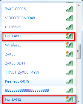
94 2.4G Band 5G Band (3) Apply AP profiles to the Local AP interface Go to Configuration > Wireless > AP Management and click the local AP (IP address is ) to edit the rule. Apply the AP profiles to this rule. Verification: If you have connected to For_LAN1 SSID, then you will get the LAN1 subnet IP address. If you connect to For_LAN2, then you will get the LAN2 subnet IP address. 93
95 94
96 Scenario 15 Device HA on the USG 15.1 Application Scenario Setup the Device HA environment. Master device Backup device WAN interface IP / /24 WAN Management IP / /24 LAN1 Interface IP / /24 LAN1 Management IP / /24 Cluster ID Configuration Guide On Master setting: (1) Go to Configuration > Network > Interface > Ethernet to check the WAN and LAN interface setting. WAN interface is: /24 LAN interface is: /24 95
97 (2) Go to Configuration > Device HA > Activate-Passive Mode to add the management interface on the master device. The Device Role must be set as Master. WAN management IP address is: LAN management IP address is: (3) Go to Configuration > Device HA > General to enable the Device HA function. After you have enabled the Device HA function, you will see the interface that was monitored above. On Backup setting: (4) Go to Configuration > Network > Interface > Ethernet to check the WAN and LAN interface setting. WAN interface is: /24 LAN interface is: /24 (5) Go to Configuration > Device HA > Activate-Passive Mode to add the management interface on the backup device. The Device Role must se as Backup. WAN management IP address is: LAN management IP address is:

98 (6) Go to Configuration > Device HA > General to enable Device HA function. After you have enabled the Device HA function, you will saw the interface that was monitored above. Verification: You can check the status of the Device HA in the GUI. The status of the master device will be Master/Activate. The status of the backup device will be Backup/Stand-By 97
99 Tutorial 1: How to Set Up Your Network Here are examples of using the Web Configurator to set up your network in the USG. Note: The tutorials featured here require a basic understanding of connecting to and using the Web Configurator,. For field descriptions of individual screens, see the Web Configurator Online Help. 1.1 Wizard Overview Use the wizards to quickly configure Internet connection and VPN settings as well as activate subscription services. WIZARD Installation Setup Wizard Quick Setup WAN Interface VPN Setup DESCRIPTION Use this wizard the first time log into the Web Configurator to configure WAN connections and register your USG. You can find the following wizards in the CONFIGURATION navigation panel. Use these wizard screens to quickly configure a WAN interface s encapsulation and IP address settings. Use these wizard screens to quickly configure an IPSec VPN or IPSec VPN configuration provisioning. After you complete a wizard, you can go to the CONFIGURATION screens to configure advanced settings. 1.2 How to Configure Interfaces, Port Roles, and Zones This tutorial shows how to configure Ethernet interfaces, port roles, and zones for the following example configuration. The wan1 interface uses a static IP address of
100 Add P5 (lan2) to the DMZ interface (Note: In USG 20/20W, use P4 (lan2) instead of P5 in this example). The DMZ interface is used for a protected local network. It uses IP address and serves as a DHCP server by default. You want to be able to apply specific security settings for the VPN tunnel created by the Quick Setup - VPN Setup wizard (named WIZ_VPN). So you create a new zone and add WIZ_VPN to it. Figure 21 Ethernet Interface, Port Roles, and Zone Configuration Example Configure a WAN Ethernet Interface You need to assign the USG s wan1 interface a static IP address of Click Configuration > Network > Interface > Ethernet and double-click the wan1 interface s entry in the Configuration section. Select Use Fixed IP Address and configure the IP address, subnet mask, and default gateway settings and click OK Configure Port Roles Here is how to take the P5 port from the lan2 interface and add it to the dmz interface. 1 Click Configuration > Network > Interface > Port Role. 99
101 2 Under P5 select the dmz (DMZ) radio button and click Apply Configure Zones In this example you have created a WIZ_VPN tunnel through the Quick Setup - VPN Setup wizard. By default, it is assigned to the IPSec_VPN zone. Do the following to move WIZ_VPN from the IPSec_VPN zone to a new zone. 1 Click Configuration > Network > Zone and then double-click the IPSec_VPN entry. 2 Select WIZ_VPN and remove it from the Member box and click OK. 3 Back to the Configuration > Network > Zone screen and click Add in the User Configuration section. 4 Enter VPN as the new zone s name. Select WIZ_VPN and move it to the Member box and click OK. 100


102 Then you can configure firewall rules to apply specific security settings to this VPN zone. 1.3 How to Configure a Cellular Interface Use 3G cards for cellular WAN (Internet) connections. See for a supported 3G card. In this example you connect the 3G USB card before you configure the cellular interfaces but is also possible to reverse the sequence. 1 Make sure the 3G device s SIM card is installed. 2 Connect the 3G device to one of the USG s USB ports. 3 Click Configuration > Network > Interface > Cellular. Select the 3G device s entry and click Edit. 4 Enable the interface and add it to a zone. It is highly recommended that you set the Zone to WAN to apply your WAN zone security settings to this 3G connection. Leaving Zone set to none has the USG not apply any security settings to the 3G connection. Enter the PIN Code provided by the cellular 3G service provider (0000 in this example). 101

103 Note: The Network Selection is set to auto by default. This means that the 3G USB modem may connect to another 3G network when your service provider is not in range or when necessary. Select Home to have the 3G device connect only to your home network or local service provider. This prevents you from being charged using the rate of a different ISP. 5 Go to the Dashboard. The Interface Status Summary section should contain a cellular entry. When its connection status is Connected you can use the 3G connection to access the Internet. 6 The USG automatically adds the cellular interface to the system default WAN trunk. If the USG is using a user-configured trunk as its default trunk and you want this cellular interface to be part of it, use the Trunk screens to add it. This way the USG can automatically balance the traffic load amongst the available WAN connections to enhance overall network throughput. Plus, if a WAN connection goes down, the USG still sends traffic through the remaining WAN connections. For a simple test, disconnect all of the USG s wired WAN connections. If you can still access the Internet, your cellular interface is properly configured and your cellular device is working. 102
104 1.4 How to Set Up a Wireless LAN This tutorial applies only to models that include wireless LAN. You can configure different interfaces to use on the wireless LAN card. This lets you have different wireless LAN networks using different SSIDs. You can configure the WLAN interfaces before or after you install the wireless LAN card. This example shows how to create a WLAN interface that uses WPA or WPA2 security and the USG s local user database for authentication Set Up User Accounts Besides WPA-PSK, the USG also supports TTLS using PAP so you can use the USG s local user database with WPA or WPA2 instead of needing an external RADIUS server. For each WLAN user, set up a user account containing the user name and password the WLAN user needs to enter to connect to the wireless LAN. 1 Click Configuration > Object > User/Group > User and the Add icon. 2 Set the User Name to wlan_user. Enter (and re-enter) the user s password. Click OK. 3 Use the Add icon in the Configuration > Object > User/Group > User screen to set up the remaining user accounts in similar fashion Create the WLAN Interface 1 Click Configuration > Network > Interface > WLAN > Add to open the WLAN Add screen. 2 Edit this screen as follows. A (internal) name for the WLAN interface displays. You can modify it if you want to. The USG s security settings are configured by zones. Select to which security zone you want the WLAN interface to belong (the WLAN zone in this example). This determines which security settings the USG applies to the WLAN interface. Configure the SSID (ZYXEL_WPA in this example). If all of your wireless clients support WPA2, select WPA2-Enterprise as the Security Type, otherwise select WPA/WPA-2-Enterprise. Set the Authentication Type to Auth Method. The 103


105 USG can use its default authentication method (the local user database) and its default certificate to authenticate the users. Configure the interface s IP address and set it to DHCP Server. Click OK. 2 Turn on the wireless LAN and click Apply. 4 Configure your wireless clients to connect to the wireless network. 104

106 Wireless Clients Import the USG s Certificate You must import the USG s certificate into the wireless clients if they are to validate the USG s certificate. Use the Configuration > Object > Certificate > Edit screen to export the certificate the USG is using for the WLAN interface. Then do the following to import the certificate into each wireless client computer. 1 In Internet Explorer, click Tools > Internet Options > Content and click the Certificates button. 2 Click Import. 3 Use the wizard screens to import the certificate. You may need to change the Files of Type setting to All Files in order to see the certificate file. 4 When you get to the Certificate Store screen, select the option to automatically select the certificate store based on the type of certificate. 5 If you get a security warning screen, click Yes to proceed. 6 The Internet Explorer Certificates screen remains open after the import is done. You can see the newly imported certificate listed in the Trusted Root Certification Authorities tab. The values in the Issued To and Issued By fields should match those in the USG s My Certificates screen s Subject and Issuer fields (respectively). The My Certificates screen indicates what type of information is being displayed, such as Common Name (CN), Organizational Unit (OU), Organization (O) and Country (C). 105
107 Repeat the steps to import the certificate into each wireless client computer that is to validate the USG s certificate when using the WLAN interface Wireless Clients Use the WLAN Interface Wireless clients enter their username and password when they connect to the wireless network. 106
108 1.5 How to Configure Ethernet, PPP, VLAN, Bridge and Policy Routing The following table describes when to configure the Ethernet, PPP, VLAN, Bridge screens under Configuration > Network > Interface and the Configuration > Network > Routing > Policy Routing screen. Table 10 Ethernet, PPP, VLAN, Bridge and Policy Routing Screen Relationships SCREEN DESCRIPTION Ethernet PPP VLAN Bridge Policy Routing Configure this if any interface on the USG is connecting to an Ethernet network. Ethernet interfaces are the foundation for defining other interfaces and network policies. Configure this if you need your service provider to provide an IP address through PPPoE or PPTP in order to access the Internet or another network. Configure this if you want to divide your physical networks into multiple VLANs, or your service provider or an aggregated network needs the USG to recognize the VLAN tags in the packets flowing through the USG. Configure this if you want the USG to combine two or multiple network segments into one single network. Although the USG is transparent in this mode, you can still apply security checking on packets flowing through the USG. Configure this if you want to override the USG s default routing behavior in order to send packets through the appropriate interface or VPN tunnel. Since firmware version 3.00, the USG supports IPv6 configuration in these Ethernet, PPP, VLAN, Bridge and Policy Route screens under Configuration > Network > Interface and Configuration > Network > Routing. Basically, these are the same as the ones for IPv4 networks except the following differences: You have to enable IPv6 globally in the CONFIGURATION > System > IPv6 screen to make the IPv6 settings work. An Enable IPv6 setting - Select this in the screens listed above to enable the USG to be able to send and receive IPv6 packets through the interface. Otherwise, the USG discards IPv6 packets flowing through the interface. IPv6 Address Assignment - This section allows you to enable auto-configuration and configure prefix delegation. DHCPv6 Setting - This section allows you to configure the DHCPv6 role and the corresponding settings for the interface. 107
109 1.6 How to Set Up IPv6 Interfaces For Pure IPv6 Routing This example shows how to configure your USG Z s WAN and LAN interfaces which connects two IPv6 networks. USG Z periodically advertises a network prefix of 2006:1111:1111:1111::/64 to the LAN through router advertisements. Note: Instead of using router advertisement, you can use DHCPv6 to pass the network settings to the computers on the LAN. Figure 22 Pure IPv6 Network Example Setting Up the WAN IPv6 Interface 1 In the CONFIGURATION > Network > Interface > Ethernet screen s IPv6 Configuration section, double-click the wan1. 2 The Edit Ethernet screen appears. Select Enable Interface and Enable IPv6. Select Enable Auto-Configuration. Click OK. Note: Your ISP or uplink router should enable router advertisement Setting Up the LAN Interface 108
110 1 In the CONFIGURATION > Network > Interface > Ethernet screen, double-click the lan1 in the IPv6 Configuration section. 2 The Edit Ethernet screen appears. Select Enable Interface and Enable IPv6. Select Enable Router Advertisement and click Add and configure a network prefix for the LAN1 (2006:1111:1111:1111::/64 in this example). Click OK. You have completed the settings on the USG. But if you want to request a network address prefix from your ISP for your computers on the LAN, you can configure prefix delegation Prefix Delegation and Router Advertisement Settings This example shows how to configure prefix delegation on the USG s WAN and router advertisement on the LAN Apply a Network Prefix From Your ISP First of all, you have to apply a network prefix from your ISP or the uplink router s administrator. The WAN port s DUID is required when you apply the prefix. You can check the DUID information in the WAN IPv6 Interface Edit screen. This example assumes that you were given a network prefix of 2001:b050:2d::/48 and you decide to divide it and give 2001:b050:2d:1111::/64 to the LAN network. LAN1 s IP address is 2001:b050:2d:1111::1/128. Figure 23 Pure IPv6 Network Example Using Prefix Delegation 109

111 Setting Up the WAN IPv6 Interface 1 In the Configuration > Network > Interface > Ethernet screen s IPv6 Configuration section, double-click the wan1. 2 The Edit Ethernet screen appears. Select Enable Interface and Enable IPv6. Click Create new Object to add a DHCPv6 Request object with the Prefix Delegation type. Select Enable Auto-Configuration. Select Client in the DHCPv6 field. (WAN1 s DUID appears.) Click Add in the DHCPv6 Request Options table and select the DHCPv6 request object you just created. You cannot see the prefix your ISP gave you in the Value field until you click OK and then come back to this screen again. It is 2001:b050:2d::/48 in this example. Note: Your ISP or a DHCPv6 server in the same network as the WAN should assign an IPv6 IP address for the WAN interface. 110
112 Setting Up the LAN Interface 1 In the Configuration > Network > Interface > Ethernet screen, double-click the lan1 in the IPv6 Configuration section. 2 The Edit Ethernet screen appears. Click Show Advanced Settings to display more settings on this screen. Select Enable Interface and Enable IPv6. In the Address from DHCPv6 Prefix Delegation table, click Add and select the DHCPv6 request object from the drop-down list, type ::1111:0:0:0:1/128 in the Suffix Address field. (The combined address 2001:b050:2d:1111::1/128 will display as LAN1 s IPv6 address after you click OK and come back to this screen again). Note: You can configure the IPv6 Address/Prefix Length field instead if the delegated prefix is never changed. Select Enable Router Advertisement. In the Advertised Prefix from DHCPv6 Prefix Delegation table, click Add and select the DHCPv6 request object from the drop-down list, type ::1111/64 in the Suffix Address field. (The combined prefix 2001:b050:2d:1111::/64 will display for the LAN1 s network prefix after you click OK and come back to this screen again). 111
113 1.6.4 Test 1 Connect a computer to the USG s LAN1. 112
114 2 Enable IPv6 support on you computer. In Windows XP, you need to use the IPv6 install command in a Command Prompt. In Windows 7, IPv6 is supported by default. You can enable IPv6 in the Control Panel > Network and Sharing Center > Local Area Connection screen. 3 Your computer should get an IPv6 IP address (starting with 2001:b050:2d:1111: for this example) from the USG. 4 Open a web browser and type If your IPv6 settings are correct, you can see a dancing turtle in the website What Can Go Wrong? 1 If you forgot to enable Auto-Configuration on the WAN1 IPv6 interface, you will not have any default route to forward the LAN s IPv6 packets. 2 To use prefix delegation, you must set the WAN interface to a DHCPv6 client, enable router advertisements on the LAN interface as well as configure the Advertised Prefix from DHCPv6 Prefix Delegation table. 3 If the Value field in the WAN1 s DHCPv6 Request Options table displays n/a, contact your ISP for further support. 4 In Windows, some IPv6 related tunnels may be enabled by default such as Teredo and 6to4 tunnels. It may cause your computer to handle IPv6 packets in an unexpected way. It is recommended to disable those tunnels on your computer. 1.7 How to Set Up an IPv6 6to4 Tunnel This example shows how to use the interface configuration screens to create the following 6to4 tunnel. Figure 24 6to4 Tunnel Example In this example, the USG (Z) acts as a 6to4 router which connects the IPv4 Internet (through WAN1 with an IP address of ) and an IPv6 intranet network. In the 6to4 tunnel application, you must configure the LAN1 with an IP address starting with 2002:7a64:dcee::/48 if you decide to use the WAN1 IP address to forward 6to4 packets to the IPv4 network. The second and third sets of 16-bit IP address from the left must be converted from It becomes 7a64:dcee in hexadecimal. You are free to use the fourth set of 16-bit IP address from the left in order to allocate different network addresses (prefixes) to IPv6 interfaces. In this example, 113
115 the LAN1 network address is assigned to use 2002:7a64:dcee:1::/64 and the LAN1 IP address is set to 2002:7a64:dcee:1::111/128. A relay router R ( ) is used in this example in order to forward 6to4 packets to any unknown IPv6 addresses Configuration Concept After the 6to4 tunnel settings are complete, IPv4 and IPv6 packets transmitted between WAN1 and LAN1 will be handled by the USG through the following flow. Figure 25 6to4 Tunnel Configuration Concept Setting Up the LAN IPv6 Interface 1 In the CONFIGURATION > Network > Interface > Ethernet screen s IPv6 Configuration section, double-click the lan1. 2 The Edit Ethernet screen appears. Select Enable Interface and Enable IPv6. Type 2002:7a64:dcee:1::111/128 in the IPv6 Address/Prefix Length field for the LAN1 s IP address. Enable Router Advertisement. Then click Add in the Advertised Prefix Table to add 2002:7a64:dcee:1::/64. The LAN1 hosts will get the network prefix through the router advertisement messages sent by the LAN1 IPv6 interface periodically. Click OK. 114
116 1.7.3 Setting Up the 6to4 Tunnel 1 Click Add in the CONFIGURATION > Network > Interface > Tunnel screen. 2 The Add Tunnel screen appears. Select Enable. Enter tunnel0 as the Interface Name and select 6to4 as the Tunnel Mode. In the 6to4 Tunnel Parameter section, this example just simply uses the default 6to4 Prefix, 2002:://16. Enter your relay router s IP address ( in this example). Select wan1 as the gateway. Click OK. 115
117 1.7.4 Testing the 6to4 Tunnel 1 Connect a computer to the USG s LAN1. 2 Enable IPv6 support on you computer. In Windows XP, you need to use the IPv6 install command in a Command Prompt. In Windows 7, IPv6 is supported by default. You can enable IPv6 in the Control Panel > Network and Sharing Center > Local Area Connection screen. 3 You should get an IPv6 IP address starting with 2002:7a64:dcee:1:. 4 Type ping -6 ipv6.google.com in a Command Prompt to test. You should get a response What Can Go Wrong? 1 Do not enable Auto-Configuration for the LAN1 IPv6 interface. Enabling it will cause two default routes, however, the USG only needs a default route generated by your relay router setting. In 6to4, the USG doesn t need a policy route to determine where to forward a 6to4 packet (starting with 2002 in the IPv6 IP address). The next gateway information of where to forward a 6to4 packet can be retrieved from the packet s destination IP address. The USG only forwards a 6to4 packet to the relay router using the default route if the packet s destination is not an IP address starting with You don t need to activate the WAN1 IPv6 interface but make sure you enable the WAN1 IPv4 interface. In 6to4, the USG uses the WAN1 IPv4 interface to forward your 6to4 packets over the IPv4 network. Note: For 6to4, you do not need to enable IPv6 in the wan1 since the IPv6 packets will be redirected into the 6to4 tunnel. 116

118 3 In Windows, some IPv6 related tunnels may be enabled by default such as Teredo and 6to4 tunnels. It may cause your computer to handle IPv6 packets in an unexpected way. It is recommended to disable those tunnels on your computer. 1.8 How to Set Up an IPv6-in-IPv4 Tunnel This example shows how to use the interface and policy route configuration screens to create an IPv6-in-IPv4 tunnel. Figure 26 IPv6-in-IPv4 Tunnel Example In this example, the USGs (Z and Y) act as IPv6-in-IPv4 routers which connect the IPv4 Internet and an individual IPv6 network. This configuration example only shows the settings on USG Z. You can use similar settings to configure USG Y. Note: In the IPv6-in-IPv4 tunnel application, you must configure the peer gateway s WAN IPv4 address as the remote gateway IP Configuration Concept After the IPv6-in-IPv4 tunnel settings are complete, IPv4 and IPv6 packets transmitted between WAN1 and LAN1 will be handled by the USG through the following flow. Figure 27 IPv6-in-IPv4 Tunnel Configuration Concept Setting Up the IPv6-in-IPv4 Tunnel 1 Click Add in the CONFIGURATION > Network > Interface > Tunnel screen. 117

119 2 The Edit Tunnel screen appears. Select Enable. Enter tunnel0 as the Interface Name and select IPv6-in-IPv4 as the Tunnel Mode. Select wan1 in the Interface field in the Gateway Settings section. Enter as the remote gateway s IP address. Click OK Setting Up the LAN IPv6 Interface 1 Select lan1 in the IPv6 Configuration section in the CONFIGURATION > Network > Interface > Ethernet screen and click Edit. 2 The Edit Ethernet screen appears. Select Enable Interface and Enable IPv6. Type 2003:1111:1111:1::1/128 in the IPv6 Address/Prefix Length field for the LAN1 s IP address. Enable Router Advertisement. Then click Add in the Advertised Prefix Table to add 2003:1111:1111:1::/64. The LAN1 hosts will get the network prefix through router advertisements sent by the LAN1 IPv6 interface periodically. Click OK. 118

120 1.8.4 Setting Up the Policy Route 1 Go to the CONFIGURATION > Network > Routing screen and click Add in the IPv6 Configuration table. 2 The Add Policy Route screen appears. Click Create New Object to create an IPv6 address object with the address prefix of 2003:1111:1111:1::/64. Select Enable. Select the address object you just created in the Source Address field. Select any in the Destination Address field. Select Interface as the next-hop type and then tunnel0 as the interface. Click OK. 119

121 1.8.5 Testing the IPv6-in-IPv4 Tunnel 1 Connect a computer to the USG s LAN1. 2 Enable IPv6 support on you computer. In Windows XP, you need to use the IPv6 install command in a Command Prompt. In Windows 7, IPv6 is supported by default. You can enable IPv6 in the Control Panel > Network and Sharing Center > Local Area Connection screen. 3 You should get an IPv6 IP address starting with 2003:1111:1111:1000:. 4 Use the ping -6 [IPv6 IP address] command in a Command Prompt to test whether you can ping a computer behind USG Y. You should get a response What Can Go Wrong? 1 You don t need to activate the WAN1 IPv6 interface but make sure you enable the WAN1 IPv4 interface. In IPv6-in-IPv4, the USG uses the WAN1 IPv4 interface to forward your 6to4 packets to the IPv4 network. 2 In Windows, some IPv6 related tunnels may be enabled by default such as Teredo and 6to4 tunnels. It may cause your computer to handle IPv6 packets in an unexpected way. It is recommended to disable those tunnels on your computer. 120
122 Tutorial 2: Protecting Your Network These sections cover configuring the USG to protect your network. 2.1 Firewall The firewall controls the travel of traffic between or within zones for services using static port numbers. Use application patrol to control services using flexible/dynamic port numbers. The firewall can also control traffic for NAT (DNAT) and policy routes (SNAT). Firewall rules can use schedule, user, user groups, address, address group, service, and service group objects. To-USG firewall rules control access to the USG itself including management access. By default the firewall allows various types of management from the LAN, HTTPS from the WAN and no management from the DMZ. The firewall also limits the number of user sessions. This example shows the USG s default firewall behavior for WAN to LAN traffic and how stateful inspection works. A LAN user can initiate a Telnet session from within the LAN zone and the firewall allows the response. However, the firewall blocks Telnet traffic initiated from the WAN zone and destined for the LAN zone. The firewall allows VPN traffic between any of the networks. Figure 28 Default Firewall Action 121
123 2.1.1 What Can Go Wrong The USG checks the firewall rules in order and applies the first firewall rule the traffic matches. If traffic is unexpectedly blocked or allowed, make sure the firewall rule you want to apply to the traffic comes before any other rules that the traffic would also match. Even if you have configured the firewall to allow access for a management service such as HTTP, you must also enable the service in the service control rules. The USG is not applying your firewall rules for certain interfaces. The USG only apply s a zone s rules to the interfaces that belong to the zone. Make sure you assign the interfaces to the appropriate zones. When you create an interface, there is no security applied on it until you assign it to a zone. 2.2 User-aware Access Control You can configure many policies and security settings for specific users or groups of users. Users can be authenticated locally by the USG or by an external (AD, RADIUS, or LDAP) authentication server. Here is how to have the USG use a RADIUS server to authenticate users before giving them access. 1 Set up user accounts in the RADIUS server. 2 Set up user accounts and groups on the USG (Configuration > Object > User/Group). 3 Configure an object for the RADIUS server. Click Configuration > Object > AAA Server > RADIUS and double-click the radius entry. 4 Then, set up the authentication method, Click Configuration > Object > Auth. Method. Doubleclick the default entry. Click the Add icon. 5 Configure the USG s security settings. The USG can use the authentication method in authenticating wireless clients, HTTP and HTTPS clients, IPSec gateways (extended authentication), L2TP VPN, and authentication policy What Can Go Wrong The USG always authenticates the default admin account locally, regardless of the authentication method setting. You cannot have the RADIUS server authenticate the USG s default admin account. The authentication attempt will always fail if the USG tries to use the local database to authenticate an ext-user. An external server such as AD, LDAP or RADIUS must authenticate the ext-user accounts. Attempts to add the admin users to a user group with access users will fail. You cannot put 122


124 access users and admin users in the same user group. Attempts to add the default admin account to a user group will fail. You cannot put the default admin account into any user group. 2.3 Device and Service Registration This tutorial shows you how to create a myzyxel.com account and register the USG. You can then activate your service subscription. 1 You can directly create a myzyxel.com account and register the USG on the Registration screen. Click Configuration > Licensing > Registration to open the following screen. Select new myzyxel.com account. Fill in the fields marked in red in this screen. Click Apply to create your account and register the device. 2 Click the Service tab. To activate or extend a standard service subscription enter your icard s license key in the License Key field. The license key can be found on the reverse side of the icard. 123
125 2.4 Anti-Virus Policy Configuration This tutorial shows you how to configure an Anti-Virus policy. Note: You need to first activate your Anti-Virus service license or trial. See 1 Click Configuration > Anti-X > Anti-Virus to display the Anti-Virus General screen. In the Policies section click Add to display the Add Rule screen. Select Enable. In the Direction section, you can select the From and To zones for traffic to scan for viruses. You can also select traffic types to scan for viruses under Protocols to Scan. Click OK. 124

. Traffic through custom (non-standard) ports.")
126 2 The policy configured in the previous step will display in the Policies section. Select Enable Anti- Virus and Anti-Spyware and click Apply What Can Go Wrong The USG does not scan the following file/traffic types: Simultaneous downloads of a file using multiple connections. For example, when you use FlashGet to download sections of a file simultaneously. Encrypted traffic. This could be password-protected files or VPN traffic where the USG is not the endpoint (pass-through VPN traffic). Traffic through custom (non-standard) ports. The only exception is FTP traffic. The USG scans whatever port number is specified for FTP in the ALG screen. ZIP file(s) within a ZIP file. 125

127 2.5 IDP Profile Configuration IDP (Intrusion, Detection and Prevention) detects malicious or suspicious packets and protects against network-based intrusions. Note: You need to first activate your IDP service license or trial. You may want to create a new profile if not all signatures in a base profile are applicable to your network. In this case you should disable non-applicable signatures so as to improve USG IDP processing efficiency. You may also find that certain signatures are triggering too many false positives or false negatives. A false positive is when valid traffic is flagged as an attack. A false negative is when invalid traffic is wrongly allowed to pass through the USG. As each network is different, false positives and false negatives are common on initial IDP deployment. You could create a new monitor profile that creates logs but all actions are disabled. Observe the logs over time and try to eliminate the causes of the false alarms. When you re satisfied that they have been reduced to an acceptable level, you could then create an inline profile whereby you configure appropriate actions to be taken when a packet matches a signature Procedure To Create a New Profile To create a new profile: 1 Click Configuration > Anti-X > IDP > Profile and in the Profile Management section of this screen, click the Add icon. A pop-up screen will appear allowing you to choose a base profile. Select a base profile to go to the profile details screen. Note: If Internet Explorer opens a warning screen about a script making Internet Explorer run slowly and the computer maybe becoming unresponsive, just click No to continue. 2 Type a new profile Name. Enable or disable individual signatures by selecting a row and clicking Activate or Inactivate. Click OK. 126
 protects against anomalies based on violations of protocol standards (RFCs Requests for Comments) and abnormal traffic flows such as")
128 3 Edit the default log options and actions. 2.6 ADP Profile Configuration ADP (Anomaly Detection and Prevention) protects against anomalies based on violations of protocol standards (RFCs Requests for Comments) and abnormal traffic flows such as port scans. You may want to create a new profile if not all traffic or protocol rules in a base profile are applicable to your network. In this case you should disable non-applicable rules so as to improve USG ADP processing efficiency. You may also find that certain rules are triggering too many false positives or false negatives. A false positive is when valid traffic is flagged as an attack. A false negative is when invalid traffic is wrongly allowed to pass through the USG. As each network is different, false positives and false negatives are common on initial ADP deployment. You could create a new monitor profile that creates logs but all actions are disabled. Observe the logs over time and try to eliminate the causes of the false alarms. When you re satisfied that they have been reduced to an acceptable level, you could then create an inline profile whereby you configure appropriate actions to be taken when a packet matches a detection Procedure To Create a New ADP Profile To create a new profile: 1 Click Configuration > Anti-X > ADP > Profile and in the Profile Management section of this screen, click the Add icon. A pop-up screen will appear allowing you to choose a base profile. Select a base profile to go to the profile details screen. 127

129 Note: If Internet Explorer opens a warning screen about a script making Internet Explorer run slowly and the computer maybe becoming unresponsive, just click No to continue. 2 The Traffic Anomaly screen will display. Type a new profile Name. Enable or disable individual scan or flood types by selecting a row and clicking Activate or Inactivate. Selecting different levels in the Sensitivity drop-down menu adjusts levels for scan thresholds and sample times. Edit the default log options and actions by selecting a row and making a selection in the Log or Action drop-down menus. Click OK. 3 Click the Protocol Anomaly tab. Type a new profile Name. Enable or disable individual rules by selecting a row and clicking Activate or Inactivate. Edit the default log options and actions by selecting a row and making a selection in the Log or Action drop-down menus. Click OK. 128
130 2.7 Content Filter Profile Configuration Content filter allows you to control access to specific web sites or filter web content by checking against an external database. This tutorial shows you how to configure a Content Filter profile. Note: You need to first activate your Content Filter service license or trial to use Commtouch or BlueCoat content filtering service. 1 You will first configure a content filter profile. Click Configuration > Anti-X > Content Filter > Filter Profile > Add to open the following screen. Enter a profile Name and select Enable Content Filter Category Service and select desired actions for the different web page categories. Then select the categories to include in the profile or select Select All Categories. Click Apply. 129

131 2 Click the General tab and in the Policies section click Add. In the Add Policy screen that appears, select the Filter Profile you created in the previous step. Click OK. 3 In the General screen, the configured policy will appear in the Policies section. Select Enable Content Filter and select BlueCoat. Then select Enable Content Filter Report Service to collect content filtering statistics for reports. Click Apply. 130
132 2.8 Viewing Content Filter Reports Content filtering reports are generated statistics and charts of access attempts to web sites belonging to the categories you selected in your device content filter screen. You need to register your icard before you can view content filtering reports. Alternatively, you can also view content filtering reports during the free trial (up to 30 days). 1 Go to Fill in your myzyxel.com account information and click Login. 2 A welcome screen displays. Click your USG s model name and/or MAC address under Registered ZyXEL Products (the USG 20W is shown as an example here). You can change the descriptive name for your USG using the Rename button in the Service Management screen. 131


133 3 In the Service Management screen click Content Filter (BlueCoat) or Content Filter (Commtouch) in the Service Name column to open the content filter reports screens. 4 In the Web Filter Home screen, click Commtouch Report or BlueCoat Report. 5 Select items under Global Reports to view the corresponding reports. 6 Select a time period in the Date Range field, either Allowed or Blocked in the Action Taken field and a category (or enter the user name if you want to view single user reports) and click Run Report. 132


134 The screens vary according to the report type you selected in the Report Home screen. 7 A chart and/or list of requested web site categories display in the lower half of the screen. 8 You can click a category in the Categories report or click URLs in the Report Home screen to see the URLs that were requested. 133
135 2.9 Anti-Spam Policy Configuration This tutorial shows you how to configure an Anti-Spam policy with Mail Scan functions and DNS Black List (DNSBL). Note: You need to first activate your Anti-Spam service license or trial to use the Mail Scan functions (Sender Reputation, Mail Content Analysis and Virus Outbreak Detection). 1 To use the Mail Scan functions (Sender Reputation, Mail Content Analysis and Virus Outbreak Detection) you need to enable them in the Mail Scan screen. Click Configuration > Anti-X > Anti-Spam > Mail Scan to open this screen. Enable the desired Mail Scan functions. Click Apply. 2 To configure DNS Black List (DNSBL), click the DNSBL tab. Select Enable DNS Black List (DNSBL) Checking. In the DNSBL Domain section click Add. Enter the DNSBL Domain for a DNSBL service. In this example, zen.spamhaus.org is used. Click Apply. 134

136 3 Click the General tab. In the Policy Summary section, click Add to display the Add rule screen. Select from the list of available Scan Options and click OK to return to the General screen. 4 In the General screen, the policy configured in the previous step will display in the Policy Summary section. Select Enable Anti-Spam and click Apply. 135
137 Tutorial 3: Create Secure Connections Across the Internet These sections cover using VPN to create secure connections across the Internet. 3.1 IPSec VPN Besides using the VPN quick setup wizard to configure settings for an IPSec VPN tunnel, you can use the Configuration > VPN > IPSec VPN screens to configure and activate or deactivate VPN gateway and IPSec VPN connection policies. You can also connect or disconnect IPSec VPN connections. Use the VPN Gateway screens to manage the USG s VPN gateways. A VPN gateway specifies the IPSec routers at either end of a VPN tunnel and the IKE SA settings (phase 1 settings). You can also activate or deactivate each VPN gateway. Use the VPN Connection screens to specify which IPSec VPN gateway an IPSec VPN connection policy uses, which devices behind the IPSec routers can use the VPN tunnel, and the IPSec SA settings (phase 2 settings). You can also activate or deactivate and connect or disconnect each VPN connection (each IPSec SA) Test the VPN Connection 136
138 After you configure the VPN gateway and VPN connection settings, set up the VPN settings on the peer IPSec router and try to establish the VPN tunnel. To trigger the VPN, either try to connect to a device on the peer IPSec router s LAN or click Configuration > VPN > IPSec VPN > VPN Connection and use the VPN connection screen s Connect icon Configure Security Policies for the VPN Tunnel You configure security policies based on zones. The new VPN connection was assigned to the IPSec_VPN zone. By default, there are no security restrictions on the IPSec_VPN zone, so, next, you should set up security policies that apply to the IPSec_VPN zone What Can Go Wrong If the IPSec tunnel does not build properly, the problem is likely a configuration error at one of the IPSec routers. Log into both IPSec routers and check the settings in each field methodically and slowly. Make sure both the USG and remote IPSec router have the same security settings for the VPN tunnel. It may help to display the settings for both routers side-by-side. Here are some general suggestions. The system log can often help to identify a configuration problem. If you enable NAT traversal, the remote IPSec device must also have NAT traversal enabled. Both routers must use the same authentication method to establish the IKE SA. Both routers must use the same negotiation mode, encryption algorithm, authentication algorithm, and DH key group. When using manual keys, both routers must use the same encryption key and authentication key. When using pre-shared keys, both routers must use the same pre-shared key. The USG s local and peer ID type and content must match the remote IPSec router s peer and local ID type and content, respectively. Both routers must use the same active protocol, encapsulation, and SPI. If the sites are/were previously connected using a leased line or ISDN router, physically disconnect these devices from the network before testing your new VPN connection. The old route may have been learnt by RIP and would take priority over the new VPN connection. To test whether or not a tunnel is working, ping from a computer at one site to a computer at the other. Before doing so, ensure that both computers have Internet access (via the IPSec routers). It is also helpful to have a way to look at the packets that are being sent and received by the USG and remote IPSec router (for example, by using a packet analyzer such as Wireshark). Check the configuration for the following USG features. Make sure the To-USG firewall rules allow IPSec VPN traffic to the USG. IKE uses UDP port 500, AH uses IP protocol 51, and ESP uses IP protocol 50. The USG supports UDP port 500 and UDP port 4500 for NAT traversal. If you enable this, make sure the To-USG firewall rules allow UDP port 4500 too. Make sure regular firewall rules allow traffic between the VPN tunnel and the rest of the network. Regular firewall rules check packets the USG sends before the USG encrypts them and check packets the USG receives after the USG decrypts them. This depends on the zone to which you assign the VPN tunnel and the zone from which and to which traffic may be routed. If you set up a VPN tunnel across the Internet, make sure your ISP supports AH or ESP (whichever you are using). If you have the USG and remote IPSec router use certificates to authenticate each other, You must set up the certificates for the USG and remote IPSec router first and make sure they trust each other s certificates. If the USG s certificate is self-signed, import it into the remote IPsec router. If it is signed by a CA, make sure the remote IPsec router trusts that CA. The USG uses one of its Trusted Certificates to authenticate the remote IPSec router s certificate. The trusted certificate can be the remote IPSec router s self-signed certificate or that of a trusted CA that signed the 137
139 remote IPSec router s certificate. Multiple SAs connecting through a secure gateway must have the same negotiation mode. If you have the Configuration > VPN > IPSec VPN > VPN Connection screen s Use Policy Route to control dynamic IPSec rules option enabled and the VPN connection is up but VPN traffic cannot be transmitted through the VPN tunnel, check the routing policies to see if they are sending traffic elsewhere instead of through the VPN tunnels. 3.2 VPN Concentrator Example A VPN concentrator uses hub-and-spoke VPN topology to combine multiple IPSec VPN connections into one secure network. The hub routes VPN traffic between the spoke routers and itself. This reduces the number of VPN connections to set up and maintain. Here a VPN concentrator connects ZLD-based USGs at headquarters (HQ) and branch offices A and B in one secure network. Branch A s USG uses one VPN rule to access both the headquarters (HQ) network and branch B s network. Branch B s USG uses one VPN rule to access branch A s network only. Branch B is not permitted to access the headquarters network. Figure 29 IPSec VPN Concentrator Example This IPSec VPN concentrator example uses the following settings. Branch Office A VPN Gateway (VPN Tunnel 1): My Address: Peer Gateway Address: VPN Connection (VPN Tunnel 1): Local Policy: / Remote Policy: / Disable Policy Enforcement Policy Route Source:
140 Destination: Next Hop: VPN Tunnel 1 Headquarters VPN Gateway (VPN Tunnel 1): My Address: Peer Gateway Address: VPN Connection (VPN Tunnel 1): Local Policy: / Remote Policy: / Disable Policy Enforcement VPN Gateway (VPN Tunnel 2): My Address: Peer Gateway Address: VPN Connection (VPN Tunnel 2): Local Policy: / Remote Policy: / Disable Policy Enforcement Concentrator Add VPN tunnel 1 and VPN tunnel 2 to an IPSec VPN concentrator. Firewall Block traffic from VPN tunnel 2 from accessing the LAN. Branch Office B VPN Gateway (VPN Tunnel 2): My Address: Peer Gateway Address: VPN Connection (VPN Tunnel 2): Local Policy: / Remote Policy: / Disable Policy Enforcement Policy Route Source: Destination: Next Hop: VPN Tunnel What Can Go Wrong 139
141 Consider the following when using the VPN concentrator. The local IP addresses configured in the VPN rules should not overlap. The concentrator must have at least one separate VPN rule for each spoke. In the local policy, specify the IP addresses of the networks with which the spoke is to be able to have a VPN tunnel. This may require you to use more than one VPN rule for each spoke. To have all Internet access from the spoke routers go through the VPN tunnel, set the VPN rules in the spoke routers to use (any) as the remote IP address. Your firewall rules can still block VPN packets. If on a USG USG or USG 1050 the concentrator s VPN tunnels are members of a single zone, make sure it is not set to block intra-zone traffic. 3.3 Hub-and-spoke IPSec VPN Without VPN Concentrator Here is an example of a hub-and-spoke VPN that does not use the USG s VPN concentrator feature. Here branch office A has a ZyNOS-based USG and headquarters (HQ) and branch office B have ZLD-based USGs. Branch A s USG uses one VPN rule to access both the headquarters (HQ) network and branch B s network. Branch B s USG uses one VPN rule to access both the headquarters and branch A s networks. Figure 30 Hub-and-spoke VPN Example This hub-and-spoke VPN example uses the following settings. Branch Office A (ZyNOS-based USG): Gateway Policy (Phase 1): My Address: Primary Remote Gateway: Network Policy (Phase 2): Local Network: / ; Remote Network: ~ Headquarters (ZLD-based USG): VPN Gateway (VPN Tunnel 1): 140
142 My Address: Peer Gateway Address: VPN Connection (VPN Tunnel 1): Local Policy: ~ Remote Policy: / Disable Policy Enforcement VPN Gateway (VPN Tunnel 2): My Address: Peer Gateway Address: VPN Connection (VPN Tunnel 2): Local Policy: ~ Remote Policy: / Disable Policy Enforcement Branch Office B (ZLD-based USG): VPN Gateway: My Address: Peer Gateway Address: VPN Connection: Local Policy: / Remote Policy: ~ Disable Policy Enforcement What Can Go Wrong Consider the following when implementing a hub-and-spoke VPN. This example uses a wide range for the ZyNOS-based USG s remote network, to use a narrower range. The local IP addresses configured in the VPN rules should not overlap. The hub router must have at least one separate VPN rule for each spoke. In the local policy, specify the IP addresses of the hub-and-spoke networks with which the spoke is to be able to have a VPN tunnel. This may require you to use more than one VPN rule. To have all Internet access from the spoke routers to go through the VPN tunnel, set the VPN rules in the spoke routers to use (any) as the remote IP address. Your firewall rules can still block VPN packets. If the ZLD-based USGs VPN tunnels are members of a single zone, make sure it is not set to block intra-zone traffic. The ZyNOS based USGs don't have user-configured policy routes so the only way to get traffic destined for another spoke router to go through the ZyNOS USG's VPN tunnel is to make the remote policy cover both tunnels. Since the ZLD-based USGs automatically handle the routing for VPN tunnels, if a ZLD-based USG USG is a hub router and the local policy covers both tunnels, the automatic routing takes care of it without needing a VPN concentrator. 141

143 If a ZyNOS-based USG s remote network setting overlaps with its local network settings, set ipsec swskipoverlapip to on to send traffic destined to A s local network to A s local network instead of through the VPN tunnel. 3.4 USG IPSec VPN Client Configuration Provisioning VPN configuration provisioning gives USG IPSec VPN Client users VPN rule settings automatically. Figure 31 IPSec VPN Configuration Provisioning Process 1 User Charlotte with the USG IPSec VPN Client sends her user name and password to the USG. 2 The USG sends the settings for the matching VPN rule Overview of What to Do 1 Create a VPN rule on the USG using the VPN Configuration Provisioning wizard. 2 Configure a username and password for the rule on the USG. 3 On a computer, use the USG IPSec VPN Client to get the VPN rule configuration. Now user Charlotte can access the network behind the USG through the VPN tunnel. Figure 32 USG IPSec VPN Client with VPN Tunnel Connected Configuration Steps 1 In the USG Quick Setup wizard, use the VPN Settings for Configuration Provisioning wizard to create a VPN rule that can be used with the USG IPSec VPN Client. 142
144 2 Click Configuration > Object > User/Group and create a user account for the USG IPSec VPN Client user. 3 Then, enable Configuration Provisioning in Configuration > VPN > IPSec VPN > Configuration Provisioning and configure it to allow the newly created user to retrieve this rule s settings using the USG IPSec VPN Client. 4 On the USG IPSec VPN Client, select Configuration > Get From Server. 5 Enter the WAN IP address or URL for the USG. If you changed the default HTTPS port on the USG, then enter the new one here. Enter the user name (Login) and and password exactly as configured on the USG or external authentication server. Click Next. 6 Click OK. The rule settings are now imported from the USG into the USG IPSec VPN Client What Can Go Wrong VPN rule settings violate the the USG IPSec VPN Client restrictions: Check that the rule does not contain AH active protocol, NULL encryption, SHA512 authentication, or a subnet/range remote policy. The USG IPSec VPN Client can also indicate rule violations. Check its warning screen. Although the rule settings may be valid, whether the tunnel actually works depends on the network environment. For example, a remote policy IP address for a server may be valid, but the server may be down or have an actual different IP address. There is a login problem: Reenter the user name (Login) and password in the USG IPSec VPN Client exactly as configured on the USG or the external authentication server. Check that the client authentication method selected on the USG is where the user name and password are configured. For example, if the user name and password are configured on the USG, then the configured authentication method should be Local. There s a network connectivity problem between the USG and the USG IPSec VPN Client: 143
145 Check that the correct USG IP address and HTTPS port (if the default port was changed) was entered. Ping the USG from the computer on which the USG IPSec VPN Client is installed. If there is no reply, check that the computer has Internet access. If the computer has Internet access, contact the USG administrator. The entry is not activated: Make sure that both Enable Configuration Provisioning in Configuration > VPN > IPSec VPN > Configuration Provisioning is selected and that the entry has a yellow Status icon. 3.5 SSL VPN SSL VPN uses remote users web browsers to provide the easiest-to-use of the USG s VPN solutions. A user just types the USG s web address and enters his user name and password to securely access the USG s network. Here a user uses his browser to securely connect to network resources in the same way as if he were part of the internal network. Figure 33 SSL VPN Click Configuration > Object > SSL Application and configure an SSL application object to specify the type of application and the address of the local computer, server, or web site SSL users are to be able to access. Click Configuration > VPN > SSL VPN > Access Privilege to configure SSL access policies. Use the Configuration > VPN > SSL VPN > Global Setting screen to set the IP address of the USG (or a gateway device) on your network for full tunnel mode access, enter access messages or upload a custom logo to be displayed on the remote user screen. Remote users can access resources on the local network using one of the following methods: Using a supported web browser Once you have successfully logged in through the USG, you can access intranet sites, web- based applications, or web-based s using one of the supported web browsers. Using the USG SecuExtender client Once you have successfully logged into the USG, if the SSL VPN access policy has network extension enabled the USG automatically loads the USG SecuExtender client program to your computer. With the USG SecuExtender, you can access network resources, remote desktops and manage files as if you were on the local network What Can Go Wrong If you uploaded a logo to show in the SSL VPN user screens but it does not display properly, check that the logo graphic is in GIF, JPG, or PNG format. The graphic should use a resolution of 144
146 103 x 29 pixels to avoid distortion when displayed. The USG automatically resizes a graphic of a different resolution to 103 x 29 pixels. The file size must be 100 kilobytes or less. Transparent background is recommended. If users can log into the SSL VPN but cannot see some of the resource links check the SSL application object s configuration. If the user account is not included in an SSL VPN access policy, the USG redirects the user to the user aware screen. Operating system and browser requirements for the remote user s computer: Windows 7 (32 or 64-bit), Vista (32 or 64-bit), 2003 (32-bit), XP (32-bit), or 2000 (32-bit) Internet Explorer 7 and above or Firefox 1.5 and above Using RDP requires Internet Explorer Sun s Runtime Environment (JRE) version 1.6 or later installed and enabled. Changing the HTTP/HTTPS configuration disconnects SSL VPN network extension sessions. Users need to re-connect if this happens. 3.6 L2TP VPN with Android, ios, and Windows L2TP VPN uses the L2TP and IPSec client software included in remote users Android, ios, or Windows operating systems for secure connections to the network behind the USG. 1 L2TP VPN uses one of the USG s IPSec VPN connections. Edit Default_L2TP_VPN_GW as follows: Set My Address to the WAN interface domain name or IP address you want to use. Replace the default Pre-Shared Key. 2 Create a host-type address object containing the My Address IP address configured in the Default_L2TP_VPN_GW and set the Default_L2TP_VPN_Connection s Local Policy to use it. 3 In Configuration > VPN > L2TP VPN enable the connection and set the VPN connection L2TP VPN uses, the L2TP client IP address pool, the authentication method, and the allowed users. 4 Configure a policy route to let remote users access resources on the network behind the USG. Set the policy route s Source Address to the address object that you want to allow the remote users to access (LAN1_SUBNET in the following example). Set the Destination Address to the IP address pool that the USG assigns to the remote users (L2TP_POOL in the following example). Set the next hop to be the VPN tunnel you are using for L2TP L2TP VPN Example Here a sales representative uses a laptop to securely connect to the USG s network. Figure 34 L2TP VPN Example 145
147 The USG has a WAN interface with a static IP address of The remote user has a dynamic public IP address and connects through the Internet. You configure an IP address pool object named L2TP_POOL to assign the remote users IP addresses from to for use in the L2TP VPN tunnel. The VPN rule allows the remote user to access the LAN1_SUBNET (the x subnet). Do the following to configure the L2TP VPN example: 146


148 1 Click Configuration > VPN > IPSec VPN > VPN Gateway and double-click the Default_L2TP_VPN_GW entry. Select Enable. Set My Address. This example uses a WAN interface with static IP address Set Authentication to Pre-Shared Key and configure a password. This example uses topsecret. Click OK. 2 Click the VPN Connection tab and double-click the Default_L2TP_VPN_Connection entry. Click Create New Object > Address and create a host type address object that contains the My Address IP address you configured in the Default_L2TP_VPN_GW. The address object in this example uses the WAN interface s IP address ( ) and is named L2TP_IFACE. Select Enable, set Application Scenario to Remote Acces and Local Policy to L2TP_IFACE, and click OK. 147
149 3 Click Configuration > VPN > L2TP VPN and then Create New Object > Address to create an IP address pool for the L2TP VPN clients. This example uses L2TP_POOL with a range of to Click Create New Object > User/Group to create a user object for the users allowed to use the tunnel. This example uses a user object named L2TP-test. Enable the connection. Set VPN Connection to Default_L2TP_VPN_Connection. Set IP Address Pool to L2TP_POOL. Select the authentication method (default in this example), and select the users that can use the tunnel (L2TP-test in this example) Configuring Policy Routing You must also configure a policy route to let remote users access resources on the network behind the USG. Set the policy route s Source Address to the address object that you want to allow the remote users to access (LAN_1SUBNET in this example). Set the Destination Address to the IP address pool that the USG assigns to the remote users (L2TP_POOL in this example)). Set the next hop to be the VPN tunnel that you are using for L2TP VPN. 148
150 USG s return traffic back through the L2TP VPN tunnel. Set Incoming to USG. Set Destination Address to the L2TP address pool. Set the next hop to be the VPN tunnel that you are using for L2TP. If some of the traffic from the L2TP clients needs to go to the Internet, create a policy route to send traffic from the L2TP tunnels out through a WAN trunk. Set Incoming to Tunnel and select your L2TP VPN connection. Set the Source Address to the L2TP address pool. Set the Next-Hop Type to Trunk and select the appropriate WAN trunk To configure L2TP VPN in an Android device, go to Menu > Settings > Wireless & networks > VPN settings > Add VPN > Add L2TP/IPSec PSK VPN and configure as follows.. 149
151 VPN name is for the user to identify the VPN configuration. Set VPN server is the USG s WAN IP address. Set IPSec pre-shared key is the pre-shared key of the IPSec VPN gateway the USG uses for L2TP VPN over IPSec (top-secret in this example). Enable L2TP secret turn this off. DNS search domain leave this on. When dialing the L2TP VPN, the user will have to enter his account and password Configuring L2TP VPN in ios To configure L2TP VPN in an ios device, go to Settings > VPN > Add VPN Configuration > L2TP and configure as follows. Description is for the user to identify the VPN configuration. Server is the USG s WAN IP address. Account is the user s account for using the L2TP VPN (L2TP-test in this example). RSA SecurID leave this off. Password is the password for the user s account. Secret is the pre-shared key of the IPSec VPN gateway the USG uses for L2TP VPN over IPSec (top-secret in this example). Send All Traffic leave this on. Proxy leave this off Configuring L2TP VPN in Windows The following sections cover how to configure L2TP in remote user computers using Windows 7, Vista, or XP Configuring L2TP in Windows 7 or Windows Vista Do the following to establish an L2TP VPN connection. Create a Connection Object 1 Open the Network and Sharing Center screen. Windows 7: click Start > Control Panel > View network status and tasks > Set up a new connection or network. Windows Vista: click Start > Network > Network and Sharing Center > Set up a connection or network). 2 Select Connect to a workplace and click Next. 3 Select Use my Internet connection (VPN). 4 For the Internet address enter the My Address domain name or WAN IP address of the VPN gateway the USG is using for L2TP VPN ( in this example). 4a 4b For the Destination name, specify a name to identify this VPN (L2TP to USG for example). Select Don t connect now, just set it up so I can connect later and click Next. 150
. Then click Advanced settings.")
152 4 Enter your USG user name and password and click Create. 6 Click Close. Configure the Connection Object 1 In the Network and Sharing Center screen, click Connect to a network. Right-click the L2TP VPN connection and select Properties. 2 In Windows 7, click Security and set the Type of VPN to Layer 2 Tunneling Protocol with IPsec (L2TP/IPSec). Then click Advanced settings. In Windows Vista, click Networking. Set the Type of VPN to L2TP IPSec VPN and click IPSec Settings. 151
153 2 Select Use preshared key for authentication and enter the pre-shared key of the VPN gateway entry the USG is using for L2TP VPN (top-secret in this example). Click OK to save your changes and close the Advanced Properties screen. Then click OK again to close the Properties window. 4 If a warning screen about data encryption not occurring if PAP or CHAP is negotiated, click Yes. When you use L2TP VPN to connect to the USG, the USG establishes an encrypted IPSec VPN tunnel first and then builds an L2TP tunnel inside it. The L2TP tunnel itself does not need encryption since it is inside the encrypted IPSec VPN tunnel. Connect Using L2TP VPN 1 In the Network and Sharing Center screen, click Connect to a network, select the L2TP VPN connection and click Connect to display a login screen. Enter the user name and password of your USG user account and click Connect. 152
154 2 A window appears while the user name and password are verified. The Connect to a network screen shows Connected after the L2TP over IPSec VPN tunnel is built. 3 After the connection is up a connection icon displays in your system tray. Click it and then the L2TP connection to open a status screen. 4 Click the L2TP connection s View status link to open a status screen. 5 Click Details to see the address that you received is from the L2TP range you specified on the USG ( in the example). 153
 to make sure the computer is")

155 6 Access a server or other network resource behind the USG to make sure your access works Configuring L2TP in Windows XP In Windows XP, first issue the following command from the Windows command prompt (including the quotes) to make sure the computer is running the Microsoft IPSec service. net start "ipsec services". Then do the following to establish an L2TP VPN connection. 1 Click Start > Control Panel > Network Connections > New Connection Wizard. 2 Click Next in the Welcome screen. 3 Select Connect to the network at my workplace and click Next. 4 Select Virtual Private Network connection and click Next. 5 Type L2TP to USG as the Company Name. 154
156 6 Select Do not dial the initial connection and click Next. 7 Enter the domain name or WAN IP address configured as the My Address in the VPN gateway configuration that the USG is using for L2TP VPN ( in this example). 8 Click Finish. 9 The Connect L2TP to USG screen appears. Click Properties > Security. 10 Click Security, select Advanced (custom settings) and click Settings. 11 Select Optional encryption (connect even if no encryption) and the Allow these protocols 155


157 radio button. Select Unencrypted password (PAP) and clear all of the other check boxes. Click OK. 12 Click IPSec Settings. 13 Select the Use pre-shared key for authentication check box and enter the pre-shared key used in the VPN gateway configuration that the USG is using for L2TP VPN. Click OK. 14 Click Networking. Select L2TP IPSec VPN as the Type of VPN. Click OK. 156


158 15 Enter the user name and password of your USG account. Click Connect. 16 A window appears while the user name and password are verified. 17 A USG-L2TP icon displays in your system tray. Double-click it to open a status screen. 18 Click Details to see the address that you received from the L2TP range you specified on the USG ( ). 19 Access a server or other network resource behind the USG to make sure your access works What Can Go Wrong The IPSec VPN connection must: Be enabled Use transport mode Not be a manual key VPN connection 157
159 Use Pre-Shared Key authentication Use a VPN gateway with the Secure Gateway set to if you need to allow L2TP VPN clients to connect from more than one IP address. Disconnect any existing L2TP VPN sessions before modifying L2TP VPN settings. The remote users must make any needed matching configuration changes and re-establish the sessions using the new settings. 158
160 Tutorial 4: Managing Traffic These sections cover controlling the traffic going through the USG. 4.1 How to Configure Bandwidth Management Bandwidth management is very useful when applications are competing for limited bandwidth. Connection and Packet Directions Bandwidth management looks at the connection s direction from the interface it was initiated on to the interface it goes out. The connection initiator sends outbound traffic and receives inbound traffic. The USG controls each flow s bandwidth as it goes out through an interface or VPN tunnel. For example, a LAN1 to WAN connection is initiated from LAN1 and goes to the WAN. Figure 36 LAN1 to WAN Connection and Packet Directions 159
161 Outbound traffic goes from a LAN1 device to the WAN. The USG applies bandwidth management before sending the packets out a WAN interface. Inbound traffic comes back from the WAN to the LAN1 device. The USG applies bandwidth management before sending the traffic out a LAN1 interface. You can set outbound and inbound guaranteed and maximum bandwidths for an application Bandwidth Allocation Example Say a 10-person office has WAN1 connected to a 50 Mbps downstream and 5 Mbps upstream VDSL line and you want to allocate bandwidth for the following: SIP: Up to 10 simultaneous 100 Kbps calls guaranteed Video conferencing: Up to 10 simultaneous 128 Kbps Skype video calls guaranteed Video streaming: up to 10 simultaneous 256 Kbps sessions HTTP: Internet access including downloading files for 10 users SMTP: 10 users sending POP3: 10 users receiving FTP: 10 users uploading and downloading files Here is an example of allocating the any to WAN connection s inbound and outbound packet flows. Enable Maximize Bandwidth Usage (Max B.U.) on a packet flow to set no limit on it and let it use any available bandwidth on the out-going interface. Table Mbps / 5 Mbps Connection Any to WAN Bandwidth Allocation Example PRIORITY AND APPLICATION GUARANTEED K / MAXIMUM K OR MAX B.U. INBOUND OUTBOUND 1 SIP 1000/ / Video conferencing 1280/ / Video streaming 2560/3584 * 4 HTTP 10240/46080 * 4 SMTP * 2048/Max B.U. 4 POP /Max B.U. * 5 FTP 10240/ /3072 Total guaranteed bandwidth: Kbps 5120 Kbps * This application does not usually generate enough traffic in this direction to require management Setting the Interface s Bandwidth Use the Configuration > Interface screens to set the WAN1 interface s upstream (egress) bandwidth to be equal to (or slightly less than) what the connected device can support. This example uses 5120 Kbps SIP Bandwidth Management The most effective way to ensure the quality of SIP calls is to go to the Configuration > BWM screen and enable BWM and select Enable Highest Bandwidth Priority for SIP Traffic. See the following section if you prefer to configure specific bandwidth management rules for SIP instead SIP Any-to-WAN and WAN-to-Any Bandwidth Management Example 160

 and maximum bandwidth to 2000 kbps and priority 1. Click OK.")
162 Manage SIP traffic going to WAN1 from users on the LAN or DMZ. Inbound and outbound traffic are both guaranteed 1000 kbps and limited to 2000 kbps. Figure 37 SIP Any-to-WAN Guaranteed / Maximum Bandwidths Example 1 In the Configuration > BWM screen, click Add. 2 In the Add Policy screen, select Enable and type SIP Any-to-WAN as the policy s name. Leave the incoming interface to any and select wan1 as the outgoing interface. Select App Patrol Service and sip as the service type. Set the inbound and outbound guaranteed bandwidth to 1000 (kbps) and maximum bandwidth to 2000 kbps and priority 1. Click OK. Note: Use App Patrol Service for the services classified by the USG s IDP packet inspection signatures. Use Service Object for pre-defined services. 2 Repeat the steps above to create another policy named SIP WAN-to-Any for calls coming in from the SIP server on the WAN. It is the same as the SIP Any-to-WAN policy, but with the directions reversed (WAN-to-Any instead of Any-to-WAN) HTTP Any-to-WAN Bandwidth Management Example Set inbound guaranteed and maximum rates as the local users on the LAN and DMZ will probably download more than they upload to the Internet. Set fourth highest priority (4) for the HTTP traffic in both directions. Figure 38 HTTP Any-to-WAN Bandwidth Management Example 161
163 1 In the Configuration > BWM screen, click Add. 2 In the Add Policy screen, select Enable and type HTTP Any-to-WAN as the policy s name. Leave the incoming interface to any and select wan1 as the outgoing interface. Select App Patrol Service and http as the service type. Set the guaranteed inbound bandwidth to (kbps) and set priority 4. Set the maximum to (kbps). Set the outbound priority to 4. Click OK. 162
164 4.1.6 FTP WAN-to-DMZ Bandwidth Management Example Suppose the office has an FTP server on the DMZ. Here is how to limit WAN1 to DMZ FTP traffic so it does not interfere with SIP and HTTP traffic. Allow remote users only 2048 kbps inbound for downloading from the DMZ FTP server but up to kbps outbound for uploading to the DMZ FTP server. Set the fifth highest priority (5) for the FTP traffic. Figure 39 FTP WAN-to-DMZ Bandwidth Management Example 1 In the Configuration > BWM screen, click Add. 2 In the Add Policy screen, select Enable and type FTP WAN-to-DMZ as the policy s name. Select wan1 as the incoming interface and dmz as the outgoing interface. Select App Patrol Service and ftp as the service type. Set inbound guaranteed bandwidth to 792 kbps, priority 5, and maximum 2048 kbps. Set outbound guaranteed bandwidth to 5120 kbps, priority 5, and maximum kbps. Click OK. 163
165 4.1.7 FTP LAN-to-DMZ Bandwidth Management Example FTP traffic from the LAN1 to the DMZ can use more bandwidth since the interfaces support up to 1 Gbps connections, but give it lower priority and limit it to avoid interference with other traffic. Limit both outbound and inbound traffic to 50 Mbps. Set fifth highest priority (5) for the FTP traffic. Figure 40 FTP LAN-to-DMZ Bandwidth Management Example 1 In the Configuration > BWM screen, click Add. 2 In the Add Policy screen, select Enable and type FTP LAN-to-DMZ as the policy s name. 164
 with priority 5 for both the inbound and outbound guaranteed bandwidth. Do not select the Maximize Bandwidth Usage. Set the maximum to 51200 (kbps). Click OK.")

166 Select lan1 as the incoming interface and dmz as the outgoing interface. Select App Patrol Service and ftp as the service type. Type (kbps) with priority 5 for both the inbound and outbound guaranteed bandwidth. Do not select the Maximize Bandwidth Usage. Set the maximum to (kbps). Click OK. Finally, in the BWM screen, select Enable BWM. Click Apply What Can Go Wrong? The outbound in the guaranteed bandwidth settings apply to traffic going from the connection initiator to the outgoing interface. The inbound refers to the reverse direction. Make sure you have registered the IDP/App.Patrol service on the USG to use App Patrol Service as the service type in the bandwidth management rules. The application patrol service uses the 165
 and 512 Kbps (wan2 or cellular1) respectively.")
167 USG s IDP packet inspection signatures to classify services. 4.2 How to Configure a Trunk for WAN Load Balancing These examples show how to configure a trunk for two WAN connections to the Internet. The available bandwidth for the connections is 1 Mbps (wan1) and 512 Kbps (wan2 or cellular1) respectively. As these connections have different bandwidth, use the Weighted Round Robin algorithm to send traffic to wan1 and wan2 (or cellular1) in a 2:1 ratio. Figure 41 Trunk Example For Dual WANs Figure 42 Trunk Example For WAN and 3G Interface You do not have to change many of the USG s settings from the defaults to set up this trunk. You only have to set up the outgoing bandwidth on each of the WAN interfaces and configure the WAN_TRUNK trunk s load balancing settings Set Up Available Bandwidth on Ethernet Interfaces Here is how to set a limit on how much traffic the USG tries to send out through each WAN interface. 1 Click Configuration > Network > Interface > Ethernet and double-click the wan1 entry. Enter the available bandwidth (1000 kbps) in the Egress Bandwidth field. Click OK. 166


168 2 Repeat the process to set the egress bandwidth for wan2 to 512 Kbps. 3 For 3G interface settings, go to Configuration > Network > Interface > Cellular. Double-click the cellular1 entry and set the egress bandwidth for cellular1 to 512 Kbps Configure the WAN Trunk 1 Click Configuration > Network > Interface > Trunk. Click the Add icon. 2 Name the trunk and set the Load Balancing Algorithm field to Weighted Round Robin. Add wan1 and enter 2 in the Weight column. Add wan2 (or cellular1) and enter 1 in the Weight column. Click OK. 167

 to create the address object")
169 2 Select the trunk as the default trunk and click Apply. 4.3 How to Use Multiple Static Public WAN IP Addresses for LAN-to-WAN Traffic If your ISP gave you a range of static public IP addresses, this example shows how to configure a policy route to have the USG use them for traffic it sends out from the LAN Create the Public IP Address Range Object Click Configuration > Object > Address > Add (in IPv4 Address Configuration) to create the address object that represents the range of static public IP addresses. In this example you name it Public-IPs and it goes from to
. It is recommended to add a description. This example uses LAN-to-WAN-Range.")
170 4.3.2 Configure the Policy Route Now you need to configure a policy route that has the USG use the range of public IP addresses as the source address for WAN to LAN traffic. Click Configuration > Network > Routing > Policy Route > Add (in IPv4 Configuration). It is recommended to add a description. This example uses LAN-to-WAN-Range. Specifying a Source Address is also recommended. This example uses LAN1_SUBNET. Set the Source Network Address Translation to Public-IPs and click OK. 4.4 How to Use Device HA to Backup Your USG Use device high availability (HA) to set up an additional USG as a backup gateway to ensure the default gateway is always available for the network. Active-Passive Mode and Legacy Mode Active-passive mode has a backup USG take over if the master USG fails and is recommended for general device failover deployments. Use legacy mode if you need a more complex relationship between the master and backup USGs, such as having both USGs active or using different USGs as the master for individual interfaces. The USGs must all use the same device HA mode (either 169
171 active-passive or legacy). Management Access IP Addresses For each interface you can configure an IP address in the same subnet as the interface IP address to use to manage the USG whether it is the master or the backup. Synchronization Synchronize USGs of the same model and firmware version to copy the master USG s configuration, signatures (anti-virus, IDP/application patrol, and system protect), and certificates to the backup USG so you do not need to do it manually Active-Passive Mode Device HA Example Here active-passive mode device HA has backup USG B automatically takes over all of master USG A s functions if A fails or loses its LAN or WAN connection. An Ethernet switch connects both USGs LAN interfaces to the LAN. Whichever USG is functioning as the master uses the default gateway IP address of the LAN computers ( ) for its LAN interface and the static public IP address ( ) for its WAN interface. If USG A recovers (has both its LAN and WAN interfaces connected), it resumes its role as the master and takes over all of its functions again. Figure 43 Device HA: Master Fails and Backup Takes Over Each USG s LAN interface also has a separate management IP address that stays the same whether the USG functions as the master or a backup. USG A s management IP address is and USG B s is Figure 44 Device HA: Management IP Addresses Before You Start USG A should already be configured. You will use device HA to copy USG A s settings to B later. To 170
 and click Configuration > Device HA > Active-Passive Mode. Double-click the LAN interface s entry. 2 Configure 192.168.1.3 as the Manage IP and 255.")

172 avoid an IP address conflict, do not connect USG B to the LAN subnet until after you configure its device HA settings and the instructions tell you to deploy it Configure Device HA on the Master USG 1 Log into USG A (the master) and click Configuration > Device HA > Active-Passive Mode. Double-click the LAN interface s entry. 2 Configure as the Manage IP and as the Manage IP Subnet Mask. Click OK. 3 Set the Device Role to Master. This example focuses on the connection from the LAN to the Internet through the WAN interface, so select the LAN and WAN interfaces and click Activate. Enter a Synchronization Password ( mysyncpassword in this example). Retype the password and click Apply. 4 Click the General tab, enable device HA, and click Apply. 171
173 4.4.4 Configure the Backup USG 1 Connect a computer to USG B s LAN interface and log into its Web Configurator. Connect USG B to the Internet and subscribe it to the same subscription services (like content filtering and anti-virus) to which USG A is subscribed. See the Registration screens for more on the subscription services. 2 In USG B click Configuration > Device HA > Active-Passive Mode and the LAN interface Edit icon. 3 Configure as the Manage IP and as the Subnet Mask. Click OK. 4 Set the Device Role to Backup. Activate monitoring for the LAN and WAN interfaces. Set the Synchronization Server Address to , the Port to 21, and the Password to mysyncpassword. Retype the password, select Auto Synchronize, and set the Interval to 60. Click Apply. 172
174 5 In the General tab enable device HA and click Apply Deploy the Backup USG Connect USG B s LAN interface to the LAN network. Connect USG B s WAN interface to the same router that USG A s WAN interface uses for Internet access. USG B copies A s configuration (and re-synchronizes with A every hour). If USG A fails or loses its LAN or WAN connection, USG B functions as the master Check Your Device HA Setup 1 To make sure USG B copied USG A s settings, you can log into USG B s management IP address ( ) and check the configuration. You can use the Maintenance > File Manager > Configuration File screen to save copies of the USGs configuration files that you can compare. 2 To test your device HA configuration, disconnect USG A s LAN or WAN interface. Computers on LAN should still be able to access the Internet. If they cannot, check your connections and device HA configuration. Congratulations! Now that you have configured device HA for LAN, you can use the same process for any of the USG s other local networks. For example, enable device HA monitoring on the DMZ interfaces and use an Ethernet switch to connect both USGs DMZ interfaces to your publicly available servers. 4.5 How to Configure DNS Inbound Load Balancing This example shows you how to configure the USG to respond to DNS query messages with the least loaded interface s IP address. The DNS query senders will then transmit packets to that interface instead of an interface that has a heavy load. This example assumes that your company s domain name is You want your USG s WAN1 ( ) and WAN2 ( ) to use DNS inbound load balancing to balance traffic loading coming from the Internet. 1 In the CONFIGURATION > Network > Inbound LB screen, select Enable DNS Load Balancing. Click Apply. 2 Click Add in the Configuration table. The following screen appears. Select Enable, enter *.example.com as the Query Domain Name. Enter 300 in the Time to Live field to have DNS query senders keep the resolved DNS entries on 173
175 their computers for 5 minutes. Select any in the IP Address field and WAN in the Zone field to apply this rule for all DNS query messages the WAN zone receives. Select Least Load - Total as the load balancing algorithm. Click Add to add WAN1 and WAN2 as the member interfaces. Click OK. Continue to go to the Configuration > Firewall and Configuration > Network > NAT screens to configure the corresponding firewall rules and NAT virtual server for the inbound service access What Can Go Wrong? Using a greater TTL value makes DNS inbound load balancing become ineffective, although it can reduce the USG s loading as the DNS request senders does not need to send new queries to the USG that often. If you choose Custom in the Load Balancing Member screen and enter another IP address for a member interface, make sure the entered IP address is configured in the corresponding firewall and NAT virtual server rules. 174
176 4.6 How to Allow Public Access to a Web Server This is an example of making an HTTP (web) server in the DMZ zone accessible from the Internet (the WAN zone). In this example you have public IP address that you will use on the WAN interface and map to the HTTP server s private IP address of Figure 45 Public Server Example Network Topology Configure NAT Create a NAT rule to send HTTP traffic coming to WAN IP address to the HTTP server s private IP address of Click Configuration > Network > NAT > Add > Create New Object > Address and create an IPv4 host address object named DMZ_HTTP for the HTTP server s private IP address of Repeat to create a host address object named Public_HTTP_Server_IP for the public WAN IP address Configure the NAT rule. For the Incoming Interface select the WAN interface. Set the Original IP to the Public_HTTP_Server_IP object and the Mapped IP to the DMZ_HTTP object. HTTP traffic and the HTTP server in this example both use TCP port 80. So you set the Port Mapping Type to Port, the Protocol Type to TCP, and the original and mapped ports to 80. Keep Enable NAT Loopback selected to allow users connected to other interfaces to access the HTTP server. 175

177 4.6.2 Set Up a Firewall Rule Create a firewall rule to allow the public to send HTTP traffic to IP address in order to access the HTTP server. If a domain name is registered for IP address , users can just go to the domain name to access the web server. Click Configuration > Firewall > Add. Set the From field as WAN and the To field as DMZ. Set the Destination to the HTTP server s DMZ IP address object (DMZ_HTTP). DMZ_HTTP is the destination because the USG applies NAT to traffic before applying the firewall rule. Set the Access field to allow and the Service to HTTP, and click OK What Can Go Wrong 176
178 The USG checks the firewall rules in order and applies the first firewall rule the traffic matches. If traffic matches a rule that comes earlier in the list, it may be unexpectedly blocked. The USG does not apply the firewall rule. The USG only apply s a zone s rules to the interfaces that belong to the zone. Make sure the WAN interface is assigned to WAN zone. 4.7 How to Manage Voice Traffic Here are examples of allowing H.323 and SIP traffic through the USG How to Allow Incoming H.323 Peer-to-peer Calls Suppose you have a H.323 device on the LAN for VoIP calls and you want it to be able to receive peer-to-peer calls from the WAN. Here is an example of how to configure NAT and the firewall to have the USG forward H.323 traffic destined for WAN IP address to a H.323 device located on the LAN and using IP address Figure 46 WAN to LAN H.323 Peer-to-peer Calls Example Turn On the ALG Click Configuration > Network > ALG. Select Enable H.323 ALG and Enable H.323 transformations and click Apply. Figure 47 Configuration > Network > ALG Set Up a NAT Policy For H.323 In this example, you need a NAT policy to forward H.323 (TCP port 1720) traffic received on the 177
.")
179 USG s WAN IP address to LAN IP address Click Configuration > Network > NAT > Add > Create New Object > Address and create an IPv4 host address object for the public WAN IP address (called WAN_IP-for-H323 here). Repeat to create an address object for the H.323 device s private LAN IP address (called LAN_H323 here). Configure a name for the rule (WAN-LAN_H323 here). You want the LAN H.323 device to receive peer-to-peer calls from the WAN and also be able to initiate calls to the WAN so you set the Classification to NAT 1:1. Set the Incoming Interface to the WAN interface. Set the Original IP to the WAN address object (WAN_IP-for-H323). Set the Mapped IP to the H.323 device s LAN IP address object (LAN_H323). Set the Port Mapping Type to Port, the Protocol Type to TCP and the original and mapped ports to Click OK Set Up a Firewall Rule For H.323 Configure a firewall rule to allow H.323 (TCP port 1720) traffic received on the WAN_IP-for-H323 IP address to go to LAN IP address Click Configuration > Firewall > Add. In the From field select WAN. In the To field select LAN1. Configure a name for the rule (WAN-to-LAN_H323 here). Set the Destination to the H.323 device s LAN1 IP address object (LAN_H323). LAN_H323 is the destination because the USG applies NAT to traffic before applying the firewall rule. Set the Service to H.323. Click OK. 178


180 4.7.2 How to Use an IPPBX on the DMZ This is an example of making an IPPBX x6004 using SIP in the DMZ zone accessible from the Internet (the WAN zone). In this example you have public IP address that you will use on the WAN interface and map to the IPPBX s private IP address of The local SIP clients are on the LAN. Figure 48 IPPBX Example Network Topology Turn On the ALG Click Configuration > Network > ALG. Select Enable SIP ALG and Enable SIP Transformations and click Apply. Figure 49 Configuration > Network > ALG Set Up a NAT Policy for the IPPBX Click Configuration > Network > NAT > Add > Create New Object > Address and create an IPv4 host address object for the IPPBX s private DMZ IP address of Repeat to create a host address object named IPPBX-Public for the public WAN IP address Configure a name for the rule (WAN-DMZ_IPPBX here). You want the IPPBX to receive calls from the WAN and also be able to send calls to the WAN so you set the Classification to NAT 1:1. 179
.")
181 Set the Incoming Interface to use the WAN interface. Set the Original IP to the WAN address object (IPPBX-Public). If a domain name is registered for IP address , users can use it to connect to for making SIP calls. Set the Mapped IP to the IPPBX s DMZ IP address object (IPPBX-DMZ). Set the Port Mapping Type to Port, the Protocol Type to UDP and the original and mapped ports to Keep Enable NAT Loopback selected to allow the LAN users to use the IPPBX. Click OK. Figure 50 Configuration > Network > NAT > Add Set Up a WAN to DMZ Firewall Rule for SIP The firewall blocks traffic from the WAN zone to the DMZ zone by default so you need to create a firewall rule to allow the public to send SIP traffic to the IPPBX. If a domain name is registered for IP address , users can use it to connect to for making SIP calls. Click Configuration > Firewall > Add. Set the From field as WAN and the To field as DMZ. Set the Destination to the IPPBX s DMZ IP address object (DMZ_SIP). IPPBX_DMZ is the destination because the USG applies NAT to traffic before applying the firewall rule. Set the Access field to allow and click OK. 180


182 Set Up a DMZ to LAN Firewall Rule for SIP The firewall blocks traffic from the DMZ zone to the LAN1 zone by default so you need to create a firewall rule to allow the IPPBX to send SIP traffic to the SIP clients on the LAN. 1 Click Configuration > Firewall > Add. Set the From field as DMZ and the To field as LAN1. Set the Destination to the IPPBX s DMZ IP address object (DMZ_SIP). Set the Source to IPPBX_DMZ. Leave the Access field to allow and click OK What Can Go Wrong The USG checks the firewall rules in order and applies the first firewall rule the traffic matches. If traffic matches a rule that comes earlier in the list, it may be unexpectedly blocked. The USG does not apply the firewall rule. The USG only apply s a zone s rules to the interfaces that belong to the zone. Make sure the WAN interface is assigned to WAN zone. 4.8 How to Limit Web Surfing and MSN to Specific People The following is an example of using application patrol (AppPatrol) to enforce web surfing and MSN 181

183 policies for the sales department of a company Set Up Web Surfing Policies Before you configure any policies, you must have already subscribed for the application patrol service. You can subscribe using the Configuration > Licensing > Registration screens or using one of the wizards. 1 Click Configuration > AppPatrol. If application patrol is not enabled, enable it, and click Apply. 2 Click Configuration > AppPatrol > Query. In the first drop down menu select By Category and in the second drop down menu select Web, then click Search. Double-click the http entry to edit it. 3 Double-click the Default policy. 182
 Click OK. 4.8.")
184 4 Change the access to Drop because you do not want anyone except authorized user groups to browse the web. Click OK. 5 Click the Add icon in the policy list. In the new policy, select Sales as the user group allowed to browse the web. (The user group should be set in the Configuration > Object > User/Group > Group > Add screen.) Click OK Set Up MSN Policies In this part of the tutorial, you can set up a recurring schedule and apply it to the MSN application patrol rule so that only the sales department is allowed to use MSN during work hours on weekdays. 1 Click Configuration > AppPatrol > Query, and in the second dropdown menu, select Instant Messager, and click Search. Then, double-click the msn entry to edit it. 183

185 2 Double-click the Default policy. 3 Change the access to Drop because you do not want anyone except the authorized user group (sales) to use MSN. Click OK. 4 Now you will need to set up a recurring schedule object first. Click Configuration > Object > Schedule. Click the Add icon for recurring schedules. 5 Give the schedule a descriptive name such as WorkHours. Set up the days (Monday through Friday) and the times (08:00-17:30) when the sales group is allowed to use MSN. Click OK. 184

186 6 Click Configuration > AppPatrol > Query, and in the second dropdown menu, select Instant Messager, and click Search. Then, double-click the msn entry to edit it. 7 Click the Add icon in the policy list. In the new policy, select WorkHours as the schedule and Sales as the user group that is allowed to use MSN at the appointed schedule. Then select forward in the Access field. Click OK to finish the setup. Now only the sales group may use MSN during work hours on week days. 185
How To Balance Out The Power Of The Usg On A Network On A Pc Or Mac Mac 2.5 (For A Mac 2) On A 2G Network On An Ipnet 2.2 (For An Ipro) On An Un
 On A 2G Network On An Ipnet 2.2 (For An Ipro) On An Un") ZyWALL USG 20/20W/50 ZLD 2.21 Support Notes Revision 1.00 August, 2010 Written by CSO Table of Contents Scenario 1 Connecting your USG to the Internet... 4 1.1 Application Scenario... 4 1.2 Configuration
ZyWALL USG 20/20W/50 ZLD 2.21 Support Notes Revision 1.00 August, 2010 Written by CSO Table of Contents Scenario 1 Connecting your USG to the Internet... 4 1.1 Application Scenario... 4 1.2 Configuration
How To Configure A Kiwi Ip Address On A Gbk (Networking) To Be A Static Ip Address (Network) On A Ip Address From A Ipad (Netware) On An Ipad Or Ipad 2 (
 To Be A Static Ip Address (Network) On A Ip Address From A Ipad (Netware) On An Ipad Or Ipad 2 (") UAG715 Support Note Revision 1.00 August, 2012 Written by CSO Scenario 1 - Trunk Interface (Dual WAN) Application Scenario The Internet has become an integral part of our lives; therefore, a smooth Internet
UAG715 Support Note Revision 1.00 August, 2012 Written by CSO Scenario 1 - Trunk Interface (Dual WAN) Application Scenario The Internet has become an integral part of our lives; therefore, a smooth Internet
ZyWALL USG ZLD 3.0 Support Notes
 2012 ZyWALL USG ZLD 3.0 Support Notes CSO ZyXEL 2/1/2012 Scenario 1 - Reserving Highest Bandwidth Management Priority for VoIP Traffic 1.1 Application scenario In an enterprise network, there are various
ISG50 Application Note Version 1.0 June, 2011
 ISG50 Application Note Version 1.0 June, 2011 Scenario 1 - ISG50 is placed behind an existing ZyWALL 1.1 Application Scenario For companies with existing network infrastructures and demanding VoIP requirements,
CREATING AN IKE IPSEC TUNNEL BETWEEN AN INTERNET SECURITY ROUTER AND A WINDOWS 2000/XP PC
 CREATING AN IKE IPSEC TUNNEL BETWEEN AN INTERNET SECURITY ROUTER AND A WINDOWS 2000/XP PC 1 Introduction Release date: 11/12/2003 This application note details the steps for creating an IKE IPSec VPN tunnel
V310 Support Note Version 1.0 November, 2011
 1 V310 Support Note Version 1.0 November, 2011 2 Index How to Register V310 to Your SIP server... 3 Register Your V310 through Auto-Provision... 4 Phone Book and Firmware Upgrade... 5 Auto Upgrade... 6
ZyWALL 5. Internet Security Appliance. Quick Start Guide Version 3.62 (XD.0) May 2004
 May 2004") ZyWALL 5 Internet Security Appliance Quick Start Guide Version 3.62 (XD.0) May 2004 Introducing the ZyWALL The ZyWALL 5 is the ideal secure gateway for all data passing between the Internet and the LAN.
ZyWALL 5 Internet Security Appliance Quick Start Guide Version 3.62 (XD.0) May 2004 Introducing the ZyWALL The ZyWALL 5 is the ideal secure gateway for all data passing between the Internet and the LAN.
Using a VPN with Niagara Systems. v0.3 6, July 2013
 v0.3 6, July 2013 What is a VPN? Virtual Private Network or VPN is a mechanism to extend a private network across a public network such as the Internet. A VPN creates a point to point connection or tunnel
How To Set Up A Vpn Tunnel Between Winxp And Zwall On A Pc 2 And Winxp On A Windows Xp 2 On A Microsoft Gbk2 (Windows) On A Macbook 2 (Windows 2) On An Ip
 On A Macbook 2 (Windows 2) On An Ip") WINXP VPN to ZyWALL Tunneling 1. Setup WINXP VPN 2. Setup ZyWALL VPN This page guides us to setup a VPN connection between the WINXP VPN software and ZyWALL router. There will be several devices we need
WINXP VPN to ZyWALL Tunneling 1. Setup WINXP VPN 2. Setup ZyWALL VPN This page guides us to setup a VPN connection between the WINXP VPN software and ZyWALL router. There will be several devices we need
ZyWALL USG Series. User s Guide. Quick Start Guide. Unified Security Gateway. Default Login Details. Version 3.30 Edition 2, 9/2013
 ZyWALL USG Series Unified Security Gateway Version 3.30 Edition 2, 9/2013 Quick Start Guide User s Guide Default Login Details LAN IP Address http://192.168.1.1 User Name admin Passwordwww.zyxel.com 1234
How To Industrial Networking
 How To Industrial Networking Prepared by: Matt Crites Product: Date: April 2014 Any RAM or SN 6xxx series router Legacy firmware 3.14/4.14 or lower Subject: This document provides a step by step procedure
VPN Configuration Guide. ZyWALL USG Series / ZyWALL 1050
 VPN Configuration Guide ZyWALL USG Series / ZyWALL 1050 2011 equinux AG and equinux USA, Inc. All rights reserved. Under copyright law, this configuration guide may not be copied, in whole or in part,
Using a VPN with CentraLine AX Systems
 Using a VPN with CentraLine AX Systems User Guide TABLE OF CONTENTS Introduction 2 What Is a VPN? 2 Why Use a VPN? 2 How Can I Set Up a VPN? 2 Important 2 Network Diagrams 2 Network Set-Up with a VPN 2
Astaro Security Gateway V8. Remote Access via L2TP over IPSec Configuring ASG and Client
 Astaro Security Gateway V8 Remote Access via L2TP over IPSec Configuring ASG and Client 1. Introduction This guide contains complementary information on the Administration Guide and the Online Help. If
UIP1868P User Interface Guide
 UIP1868P User Interface Guide (Firmware version 0.13.4 and later) V1.1 Monday, July 8, 2005 Table of Contents Opening the UIP1868P's Configuration Utility... 3 Connecting to Your Broadband Modem... 4 Setting
This chapter describes how to set up and manage VPN service in Mac OS X Server.
 6 Working with VPN Service 6 This chapter describes how to set up and manage VPN service in Mac OS X Server. By configuring a Virtual Private Network (VPN) on your server you can give users a more secure
Barracuda Link Balancer
 Barracuda Networks Technical Documentation Barracuda Link Balancer Administrator s Guide Version 2.2 RECLAIM YOUR NETWORK Copyright Notice Copyright 2004-2011, Barracuda Networks www.barracuda.com v2.2-110503-01-0503
Multi-Homing Security Gateway
 Multi-Homing Security Gateway MH-5000 Quick Installation Guide 1 Before You Begin It s best to use a computer with an Ethernet adapter for configuring the MH-5000. The default IP address for the MH-5000
Lab 4.4.8a Configure a Cisco GRE over IPSec Tunnel using SDM
 Lab 4.4.8a Configure a Cisco GRE over IPSec Tunnel using SDM Objective Scenario Topology In this lab, the students will complete the following tasks: Prepare to configure Virtual Private Network (VPN)
Technical Notes TN 1 - ETG 3000. FactoryCast Gateway TSX ETG 3021 / 3022 modules. How to Setup a GPRS Connection?
 FactoryCast Gateway TSX ETG 3021 / 3022 modules How to Setup a GPRS Connection? 1 2 Table of Contents 1- GPRS Overview... 4 Introduction... 4 GPRS overview... 4 GPRS communications... 4 GPRS connections...
STATIC IP SET UP GUIDE VERIZON 7500 WIRELESS ROUTER/MODEM
 STATIC IP SET UP GUIDE VERIZON 7500 WIRELESS ROUTER/MODEM Verizon High Speed Internet for Business Verizon High Speed Internet for Business SETTING UP YOUR NEW STATIC IP CONNECTION AND IP ADDRESS(ES) This
Gigabit Multi-Homing VPN Security Router
 As Internet becomes essential for business, the crucial solution to prevent your Internet connection from failure is to have more than one connection. PLANET is a ideal to help the SMBs increase the broadband
Windows XP VPN Client Example
 Windows XP VPN Client Example Technote LCTN0007 Proxicast, LLC 312 Sunnyfield Drive Suite 200 Glenshaw, PA 15116 1-877-77PROXI 1-877-777-7694 1-412-213-2477 Fax: 1-412-492-9386 E-Mail: support@proxicast.com
OvisLink 8000VPN VPN Guide WL/IP-8000VPN. Version 0.6
 WL/IP-8000VPN VPN Setup Guide Version 0.6 Document Revision Version Date Note 0.1 11/10/2005 First version with four VPN examples 0.2 11/15/2005 1. Added example 5: dynamic VPN using TheGreenBow VPN client
Configuring TheGreenBow VPN Client with a TP-LINK VPN Router
 Configuring TheGreenBow VPN Client with a TP-LINK VPN Router This chapter describes how to configure TheGreenBow VPN Client with a TP-LINK router. This chapter includes the following sections: Example
MN-700 Base Station Configuration Guide
 MN-700 Base Station Configuration Guide Contents pen the Base Station Management Tool...3 Log ff the Base Station Management Tool...3 Navigate the Base Station Management Tool...4 Current Base Station
Static Business Class HSI Basic Installation NETGEAR 7550
 Static Business Class HSI Basic Installation Table of Contents Multiple LAN Support... 3 Full BHSI Install Summary... 7 Physical Connections... 8 Auto Configuration... 9 Auto Configuration... 9 Gateway
Professional Integrated SSL-VPN Appliance for Small and Medium-sized businesses
 Professional Integrated Appliance for Small and Medium-sized businesses Benefits Clientless Secure Remote Access Seamless Integration behind the Existing Firewall Infrastructure UTM Security Integration
If you have questions or find errors in the guide, please, contact us under the following e-mail address:
 1. Introduction... 2 2. Remote Access via PPTP... 2 2.1. Configuration of the Astaro Security Gateway... 3 2.2. Configuration of the Remote Client...10 2.2.1. Astaro User Portal: Getting Configuration
Break Internet Bandwidth Limits Higher Speed. Extreme Reliability. Reduced Cost.
 Break Internet Bandwidth Limits Higher Speed. Extreme Reliability. Reduced Cost. Peplink. All Rights Reserved. Unauthorized Reproduction Prohibited Presentation Agenda Peplink Balance Pepwave MAX Features
Create a VPN on your ipad, iphone or ipod Touch and SonicWALL NSA UTM firewall - Part 1: SonicWALL NSA Appliance
 Create a VPN on your ipad, iphone or ipod Touch and SonicWALL NSA UTM firewall - Part 1: SonicWALL NSA Appliance This article will easily explain how to configure your Apple ipad, iphone or ipod Touch
Broadband Phone Gateway BPG510 Technical Users Guide
 Broadband Phone Gateway BPG510 Technical Users Guide (Firmware version 0.14.1 and later) Revision 1.0 2006, 8x8 Inc. Table of Contents About your Broadband Phone Gateway (BPG510)... 4 Opening the BPG510's
UTM - VPN: Configuring a Site to Site VPN Policy using Main Mode (Static IP address on both sites) i...
 i...") Page 1 of 10 Question/Topic UTM - VPN: Configuring a Site to Site VPN Policy using Main Mode (Static IP address on both sites) in SonicOS Enhanced Answer/Article Article Applies To: SonicWALL Security
Page 1 of 10 Question/Topic UTM - VPN: Configuring a Site to Site VPN Policy using Main Mode (Static IP address on both sites) in SonicOS Enhanced Answer/Article Article Applies To: SonicWALL Security
Quick Installation Guide DAP-1360. Wireless N 300 Access Point & Router
 DAP-1360 Wireless N 300 Access Point & Router BEFORE YOU BEGIN Delivery Package Access point DAP-1360 Power adapter DC 12V Ethernet cable (CAT 5E) (brochure). If any of the items are missing, please contact
Barracuda Link Balancer Administrator s Guide
 Barracuda Link Balancer Administrator s Guide Version 1.0 Barracuda Networks Inc. 3175 S. Winchester Blvd. Campbell, CA 95008 http://www.barracuda.com Copyright Notice Copyright 2008, Barracuda Networks
Sophos UTM. Remote Access via PPTP. Configuring UTM and Client
 Sophos UTM Remote Access via PPTP Configuring UTM and Client Product version: 9.000 Document date: Friday, January 11, 2013 The specifications and information in this document are subject to change without
ZyWALL USG 100/200. Unified Security Gateway. Support Notes. Revision 2.10 March, 2008
 ZyWALL USG 100/200 Unified Security Gateway Support Notes Revision 2.10 March, 2008 1 INDEX The comparison of ZyNOS and ZLD... 8 1. Deploying VPN... 9 1.1 Extended Intranets... 11 1.1.2 Site to Site VPN
Chapter 2 Connecting the FVX538 to the Internet
 Chapter 2 Connecting the FVX538 to the Internet Typically, six steps are required to complete the basic connection of your firewall. Setting up VPN tunnels are covered in Chapter 5, Virtual Private Networking.
UAG Series. Application Note. Unified Access Gateway. Version 4.00 Edition 1, 04/2014. Copyright 2014 ZyXEL Communications Corporation
 UAG Series Unified Access Gateway Version 4.00 Edition 1, 04/2014 Application Note Copyright 2014 ZyXEL Communications Corporation Table of Contents Scenario 1 How to Activate a Paid Access Hotspot...
Gigabit Multi-Homing VPN Security Router
 Gigabit Multi-Homing VPN Security Router Physical Port 1~2 x 10/100/1000 Base-T RJ-45, configurable with LAN 1 (Mirror Port) 3~4 x 10/100/1000 Base-T RJ-45, configurable with WAN 4 (WAN 4 / LAN2 / DMZ)
UAG4100 Support Notes
 2013 UAG4100 Support Notes CSO ZyXEL 2013/07/29 Table of Contents Scenario 1 Activate a Paid Access Hotspot... 2 Print ticket to access the Internet... 3 Pay with PayPal payment service to access the Internet...
NETASQ MIGRATING FROM V8 TO V9
 UTM Firewall version 9 NETASQ MIGRATING FROM V8 TO V9 Document version: 1.1 Reference: naentno_migration-v8-to-v9 INTRODUCTION 3 Upgrading on a production site... 3 Compatibility... 3 Requirements... 4
Configuring IPSec VPN Tunnel between NetScreen Remote Client and RN300
 Configuring IPSec VPN Tunnel between NetScreen Remote Client and RN300 This example explains how to configure pre-shared key based simple IPSec tunnel between NetScreen Remote Client and RN300 VPN Gateway.
Configuring the WT-4 for ftp (Infrastructure Mode)
") Introduction En Configuring the WT-4 for ftp (Infrastructure Mode) This document provides basic instructions on configuring the WT-4 wireless transmitter and a ftp server for transmission over an infrastructure
Introduction En Configuring the WT-4 for ftp (Infrastructure Mode) This document provides basic instructions on configuring the WT-4 wireless transmitter and a ftp server for transmission over an infrastructure
Configuring Global Protect SSL VPN with a user-defined port
 Configuring Global Protect SSL VPN with a user-defined port Version 1.0 PAN-OS 5.0.1 Johan Loos johan@accessdenied.be Global Protect SSL VPN Overview This document gives you an overview on how to configure
Basic IPv6 WAN and LAN Configuration
 Basic IPv6 WAN and LAN Configuration This quick start guide provides basic IPv6 WAN and LAN configuration information for the ProSafe Wireless-N 8-Port Gigabit VPN Firewall FVS318N. For complete IPv6 configuration
Linksys E800. User Guide
 User Guide Contents Contents Product overview Package contents 1 Features 1 Back view 2 Bottom view 2 Setting Up: Basics How to create a home network 3 What is a network? 3 How to set up a home network
Chapter 6 Basic Virtual Private Networking
 Chapter 6 Basic Virtual Private Networking This chapter describes how to use the virtual private networking (VPN) features of the FVG318 wireless VPN firewall. VPN communications paths are called tunnels.
P-2302HWUDL-P1. Quick Start Guide. 802.11g Wireless VoIP Station Gateway. with Built-in DECT Base Station
 P-2302HWUDL-P1 802.11g Wireless VoIP Station Gateway with Built-in DECT Base Station Quick Start Guide Version 3.60 Edition 1 3/2007 Overview The P-2302HWUDL-P1 model is a router with IEEE 802.11g wireless
Lab 8.4.2 Configuring Access Policies and DMZ Settings
 Lab 8.4.2 Configuring Access Policies and DMZ Settings Objectives Log in to a multi-function device and view security settings. Set up Internet access policies based on IP address and application. Set
F-Secure Messaging Security Gateway. Deployment Guide
 F-Secure Messaging Security Gateway Deployment Guide TOC F-Secure Messaging Security Gateway Contents Chapter 1: Deploying F-Secure Messaging Security Gateway...3 1.1 The typical product deployment model...4
DI-804HV with Windows 2000/XP IPsec VPN Client Configuration Guide
 DI-804HV with Windows 2000/XP IPsec VPN Client Configuration Guide This guide will show how to configure a Windows 2000/XP machine to make an IPsec VPN Tunnel connection to a DI-804HV. Below is the example
Advanced Administration
 BlackBerry Enterprise Service 10 BlackBerry Device Service Version: 10.2 Advanced Administration Guide Published: 2014-09-10 SWD-20140909133530796 Contents 1 Introduction...11 About this guide...12 What
Gigabit SSL VPN Security Router
 As Internet becomes essential for business, the crucial solution to prevent your Internet connection from failure is to have more than one connection. PLANET is the ideal to help the SMBs increase the
Prestige 623R-T. Quick Start Guide. ADSL Dual-link Router. Version 3.40
 Prestige 623R-T ADSL Dual-link Router Quick Start Guide Version 3.40 February 2004 Introducing the Prestige The Prestige 623R-T ADSL Dual-link Router is the ideal all-in-one device for small networks connecting
Chapter 4 Customizing Your Network Settings
 . Chapter 4 Customizing Your Network Settings This chapter describes how to configure advanced networking features of the Wireless-G Router Model WGR614v9, including LAN, WAN, and routing settings. It
Wireless Broadband Router. Manual
 Wireless Broadband Router Manual 1 Introduction... 4 Features... 4 Minimum Requirements... 4 Package Content... 4 Note... 4 Get to know the Broadband Router... 5 Back Panel... 5 Front Panel... 6 Setup
Prestige 202H Plus. Quick Start Guide. ISDN Internet Access Router. Version 3.40 12/2004
 Prestige 202H Plus ISDN Internet Access Router Quick Start Guide Version 3.40 12/2004 Table of Contents 1 Introducing the Prestige...3 2 Hardware Installation...4 2.1 Rear Panel...4 2.2 The Front Panel
Application Note: Integrate Juniper IPSec VPN with Gemalto SA Server. SASolutions@gemalto.com October 2007. www.gemalto.com
 Application Note: Integrate Juniper IPSec VPN with Gemalto SA Server SASolutions@gemalto.com October 2007 www.gemalto.com Table of contents Overview... 3 Architecture... 5 Configure Juniper IPSec on an
Configuring IPsec VPN with a FortiGate and a Cisco ASA
 Configuring IPsec VPN with a FortiGate and a Cisco ASA The following recipe describes how to configure a site-to-site IPsec VPN tunnel. In this example, one site is behind a FortiGate and another site
SingTel VPN as a Service. Quick Start Guide
 SingTel VPN as a Service Quick Start Guide Document Control # Date of Release Version # 1 25 April 2014 PT_SN20_1.0 2 3 4 5 6 Page Affected Remarks 2/33 Table of Contents 1. SingTel VPN as a Service Administration...
NF1Adv VOIP Setup Guide (for Pennytel)
") NF1Adv VOIP Setup Guide (for Pennytel) Configuring your NF1Adv for VOIP Service The following steps will take you through the process of setting up your VOIP connection. Step 1: Checking Computer Network
NF1Adv VOIP Setup Guide (for Pennytel) Configuring your NF1Adv for VOIP Service The following steps will take you through the process of setting up your VOIP connection. Step 1: Checking Computer Network
ZyWALL SSL 10. Integrated SSL-VPN Appliance. Support Notes. Revision 2.0 April. 2007
 ZyWALL SSL 10 Integrated SSL-VPN Appliance Support Notes Revision 2.0 April. 2007 1 INDEX 1. Deployment... 4 1.1 DMZ Zone...4 1.1.1 Deploy ZYWALL SSL 10 in DMZ zone... 4 1.2 NAT Mode... 20 1.2.1 Deploy
STATIC IP SET UP GUIDE
 STATIC IP SET UP GUIDE VERIZON D-LINK 2750B & ACTIONTEC GT784 WNV WIRELESS GATEWAY Verizon High Speed Internet for Business Verizon High Speed Internet for Business YOUR NEW STATIC IP CONNECTION AND SET
VPN. VPN For BIPAC 741/743GE
 VPN For BIPAC 741/743GE August, 2003 1 The router supports VPN to establish secure, end-to-end private network connections over a public networking infrastructure. There are two types of VPN connections,
INTEGRATION GUIDE. DIGIPASS Authentication for Cisco ASA 5505
 INTEGRATION GUIDE DIGIPASS Authentication for Cisco ASA 5505 Disclaimer DIGIPASS Authentication for Cisco ASA5505 Disclaimer of Warranties and Limitation of Liabilities All information contained in this
Initial Access and Basic IPv4 Internet Configuration
 Initial Access and Basic IPv4 Internet Configuration This quick start guide provides initial and basic Internet (WAN) configuration information for the ProSafe Wireless-N 8-Port Gigabit VPN Firewall FVS318N
Contents. Platform Compatibility. SonicOS
 SonicOS Contents Platform Compatibility... 1 Licensing... 2 Key Features... 2 Known Issues... 5 Resolved Issues... 7 Upgrading SonicOS Image Procedures... 8 Related Technical Documentation... 13 Platform
Firewall Defaults and Some Basic Rules
 Firewall Defaults and Some Basic Rules ProSecure UTM Quick Start Guide This quick start guide provides the firewall defaults and explains how to configure some basic firewall rules for the ProSecure Unified
Configuring High Availability for Embedded NGX Gateways in SmartCenter
 Configuring High Availability for Embedded NGX Gateways in SmartCenter February 2008 Active and Passive Gateway States Contents Introduction...1 High Availability Basics and Terminology...2 Active and
Viewing VPN Status, page 335. Configuring a Site-to-Site VPN, page 340. Configuring IPsec Remote Access, page 355
 VPN This chapter describes how to configure Virtual Private Networks (VPNs) that allow other sites and remote workers to access your network resources. It includes the following sections: About VPNs, page
A Guide to New Features in Propalms OneGate 4.0
 A Guide to New Features in Propalms OneGate 4.0 Propalms Ltd. Published April 2013 Overview This document covers the new features, enhancements and changes introduced in Propalms OneGate 4.0 Server (previously
Kerio Control. Administrator s Guide. Kerio Technologies
 Kerio Control Administrator s Guide Kerio Technologies 2015 Kerio Technologies s.r.o. Contents Installing Kerio Control....................................................... 17 Product editions.........................................................
Dramatically simplifying voice and data networking HOW-TO GUIDE. Bundle Quick Start Guide
 Dramatically simplifying voice and data networking HOW-TO GUIDE Bundle Quick Start Guide 2 edgebox How-To Guide - Table of Contents Scope of the Quick-Start Guide...3 edgebox bundles...3
Configuring Routers and Their Settings
 Configuring Routers and Their Settings When installing a router on your home network the routers settings are usually defaulted to automatically protect your home, and simplify setup. This is done because
NETASQ SSO Agent Installation and deployment
 NETASQ SSO Agent Installation and deployment Document version: 1.3 Reference: naentno_sso_agent Page 1 / 20 Copyright NETASQ 2013 General information 3 Principle 3 Requirements 3 Active Directory user
ADMINISTRATION GUIDE Cisco Small Business
 ADMINISTRATION GUIDE Cisco Small Business SA500 Series Security Appliances Cisco and the Cisco logo are trademarks or registered trademarks of Cisco and/or its affiliates in the U.S. and other countries.
Scenario: IPsec Remote-Access VPN Configuration
 CHAPTER 3 Scenario: IPsec Remote-Access VPN Configuration This chapter describes how to use the security appliance to accept remote-access IPsec VPN connections. A remote-access VPN enables you to create
SonicOS Enhanced 5.7.0.2 Release Notes
 SonicOS Contents Platform Compatibility... 1 Key Features... 2 Known Issues... 3 Resolved Issues... 4 Upgrading SonicOS Enhanced Image Procedures... 6 Related Technical Documentation... 11 Platform Compatibility
Application Note. Using a Windows NT Domain / Active Directory for User Authentication NetScreen Devices 8/15/02 Jay Ratford Version 1.
 Application Note Using a Windows NT Domain / Active Directory for User Authentication NetScreen Devices 8/15/02 Jay Ratford Version 1.0 Page 1 Controlling Access to Large Numbers of Networks Devices to
Using Cisco UC320W with Windows Small Business Server
 Using Cisco UC320W with Windows Small Business Server This application note explains how to deploy the Cisco UC320W in a Windows Small Business Server environment. Contents This document includes the following
ZyXEL IP PBX Support Note. ZyXEL IP PBX (X2002) VoIP. Support Notes
 VoIP. Support Notes") ZyXEL IP PBX (X2002) VoIP Support Notes Version 1.00 October 2008 1 Contents Overview ZyXEL IP PBX Support Note 1. How to manage and maintain your IPPBX?...3 1.1 Firmware Upgrade..3 1.2 Backing up your
ZyXEL IP PBX (X2002) VoIP Support Notes Version 1.00 October 2008 1 Contents Overview ZyXEL IP PBX Support Note 1. How to manage and maintain your IPPBX?...3 1.1 Firmware Upgrade..3 1.2 Backing up your
ZyWALL 1050. Support Notes. Internet Security Appliance. ZyWALL 1050 Support Notes. Revision 2.02 July. 2007
 ZyWALL 1050 Internet Security Appliance Support Notes Revision 2.02 July. 2007 1 INDEX 1. Deploying VPN... 8 1.1 Extended Intranets... 10 1.1.1 Site to Site VPN solutions (ZyWALL 1050 ZyWALL 1050):...
Unified Services Routers
 High-Performance VPN Protocols IPSec PPTP L2TP SSL VPN Tunnels Up to 25 (DSR-250N) Up to 35 (DSR-500/500N) Up to 70 (DSR-1000/1000N) SSL VPN tunnels Up to 5 (DSR-250N) Up to 10 (DSR-500/500N) Up to 20
Steps for Basic Configuration
 1. This guide describes how to use the Unified Threat Management appliance (UTM) Basic Setup Wizard to configure the UTM for connection to your network. It also describes how to register the UTM with NETGEAR.
Citrix Access on SonicWALL SSL VPN
 Citrix Access on SonicWALL SSL VPN Document Scope This document describes how to configure and use Citrix bookmarks to access Citrix through SonicWALL SSL VPN 5.0. It also includes information about configuring
Chapter 15: Advanced Networks
 Chapter 15: Advanced Networks IT Essentials: PC Hardware and Software v4.0 1 Determine a Network Topology A site survey is a physical inspection of the building that will help determine a basic logical
How to setup PPTP VPN connection with DI-804HV or DI-808HV using Windows PPTP client
 How to setup PPTP VPN connection with DI-804HV or DI-808HV using Windows PPTP client Make sure your DI-804HV or DI-808HV is running firmware ver.1.40 August 12 or later. You can check firmware version
Chapter 8 Router and Network Management
 Chapter 8 Router and Network Management This chapter describes how to use the network management features of your ProSafe Dual WAN Gigabit Firewall with SSL & IPsec VPN. These features can be found by
Configuring an IPSec Tunnel between a Firebox & a Check Point FireWall-1
 Configuring an IPSec Tunnel between a Firebox & a Check Point FireWall-1 This document describes how to configure an IPSec tunnel with a WatchGuard Firebox II or Firebox III (software version 4.5 or later)
WiNG 5.X How-To Guide
 WiNG 5.X How-To Guide Captive Portals Part No. TME-12-2012-01 Rev. A MOTOROLA, MOTO, MOTOROLA SOLUTIONS and the Stylized M Logo are trademarks or registered trademarks of Motorola Trademark Holdings, LLC
BR-6104K / BR-6104KP Fast Ethernet Broadband Router User s Manual
 BR-6104K / BR-6104KP Fast Ethernet Broadband Router User s Manual 1 Introduction... 4 Features... 4 Minimum Requirements... 4 Package Content... 4 Note... 4 Get to know the Broadband Router... 4 Back Panel...
Step-by-Step Guide for Creating and Testing Connection Manager Profiles in a Test Lab
 Step-by-Step Guide for Creating and Testing Connection Manager Profiles in a Test Lab Microsoft Corporation Published: May, 2005 Author: Microsoft Corporation Abstract This guide describes how to create
NBG6816. User s Guide. Quick Start Guide. Simultaneous Dual-Band Wireless AC2350 Ultra HD Media Router. Default Login Details
 NBG6816 Simultaneous Dual-Band Wireless AC2350 Ultra HD Media Router Version 1.00 Edition 1, 03/2015 Quick Start Guide User s Guide Default Login Details LAN IP http://192.168.1.1 Address (Router Mode)
1. Hardware Installation
 4 Port 10/100M Internet Broadband Router with USB Printer server Quick Installation Guide #4824904AXZZ0 1. Hardware Installation A. System Requirement Before you getting started, make sure that you meet
Chapter 8 Lab B: Configuring a Remote Access VPN Server and Client
 Chapter 8 Lab B: Configuring a Remote Access VPN Server and Client Topology Note: ISR G2 devices have Gigabit Ethernet interfaces instead of FastEthernet Interfaces. All contents are Copyright 1992 2012
NF1Adv VOIP Setup Guide (for Generic VoIP Setup)
") NF1Adv VOIP Setup Guide (for Generic VoIP Setup) Configuring your NF1Adv for VOIP Service The following steps will take you through the process of setting up your VOIP connection. Step 1: Checking Computer
NF1Adv VOIP Setup Guide (for Generic VoIP Setup) Configuring your NF1Adv for VOIP Service The following steps will take you through the process of setting up your VOIP connection. Step 1: Checking Computer
What s New in Fireware XTM v11.5.1
 What s New in Fireware XTM v11.5.1 New Features in Fireware XTM v11.5.1 Major Changes IPv6 Network Configuration and Routing FIPS 140-2 Dynamic Routing Enhancements Clientless SSO Log and Report Manager
TW100-BRV204 VPN Firewall Router
 TW100-BRV204 VPN Firewall Router Cable/DSL Internet Access 4-Port Switching Hub User's Guide Table of Contents CHAPTER 1 INTRODUCTION... 1 TW100-BRV204 Features... 1 Package Contents... 3 Physical Details...
Hosting more than one FortiOS instance on. VLANs. 1. Network topology
 Hosting more than one FortiOS instance on a single FortiGate unit using VDOMs and VLANs 1. Network topology Use Virtual domains (VDOMs) to divide the FortiGate unit into two or more virtual instances of