Ultrastab 866R Six-Channel Current Transducer User Manual
|
|
|
- Andrea Dixon
- 8 years ago
- Views:
Transcription
1 Ultrastab 866R Six-Channel Current Transducer User Manual Distributed by: GMW Associates 955 Industrial Road, San Carlos, CA USA Tel: (650) Fax: (650) Website: Manufactured by: Danfysik A/S Mollehaven 31 DK 4040 Jyllinge Denmark Tel: Fax: April Industrial Road, San Carlos, CA Tel: (650) Fax: (650) GMW Web site:

2 TABLE OF CONTENTS PAGE 1. INTRODUCTION AND SPECIFICATIONS. 1.1 Introduction Working principle Warranty RECEIVING AND UNPACKING. 2.1 Receiving the goods Instructions for unpacking INSTALLATIONS. 3.1 Installation Interlock circuit OPERATING INSTRUCTIONS. 4.1 Switching ON and Operating Instructions THEORY OF OPERATION. 5.1 General description of the Electronics Current transducer 866 & Programming of the output voltage MAINTENANCE....9 APPENDIX A - SALES REPRESENTATIVE AND SERVICE APPENDIX B VOLTAGE OUTPUT MODULES APPENDIX C SPECIFICATIONS 866R- 09A APPENDIX D DRAWINGS 88729B & 88201G & APPENDIX E DRAWINGS OA, 866R Outline... APPENDIX DRAWINGS OA, 866R Schematic... DANFYSIK A/S - DK-4040 JYLLINGE - DENMARK DOC.NO. 12A03

3 2 1.1 INTRODUCTION. The ULTRASTAB 866R system is based on the very proven precision current transducer technology. In this new configuration, named Model 866R, we have packaged the modules into a 3 to 6 channel system with a measuring capacity of up to 600A DC or 425A AC (RMS). The system can be used either as a stand-alone system or as a current range extender on high performance Power Analysers. The system is delivered as a complete system, including auxiliary power supply, mounted in a 19 rack mount cabinet, transducer heads type or or a combinations of both types and connecting cables. The basic version is equipped with 3 channels, but can be extended up to totally 6 channels. The 866R system has a standard analog output of +/- 1V and an analog current output that is depending on the chosen type of transducer, and the selected maximum primary current, when the instrument was ordered, please refer to chapter 5.3. Front view of the Ultrastab 866R with LED status information for the individual channels. Rear view of the Ultrastab 866R with connectors for the individual Transducers/ channels and 25 pole female D-sub socket for interlock connections. The grounding option is located in the left side of the cabinet. DANFYSIK A/S - DK-4040 JYLLINGE - DENMARK DOC.NO. 12A03

4 Working principle. The DANFYSIK ULTRASTAB 866R Current Transducer system is a unique design, based on the zero-flux principle for galvanic isolated precision current measurement. With the primary current conductor through the transducer head center hole and current flowing, the electronics will generate a current in the built-in compensation winding, counter-balancing the primary ampere-turns. A very sensitive and extremely low noise detector circuit will detect when zero-flux is obtained, and an analog 0 max. ±400mA or 0 - ±1V signal will be generated at the output terminals in direct proportion to the primary current. The front panels of the modules are equipped with LED s giving you the information: - Power - Normal operation - Transducer connected DANFYSIK A/S - DK-4040 JYLLINGE - DENMARK DOC.NO. 12A03

5 4 1.2 Warranty DANFYSIK A/S warrants the equipment delivered from the company to be free from any defects in materials and workmanship for a period of: 12 Months from the date of installation or max. 18 months from the date of shipment. Whichever is shortest. Within this warranty period DANFYSIK A/S will repair or replace any defective parts free of charge either on the customers site or at our factory at our choice. DANFYSIK A/S will pay or reimburse the lowest two-way freight charges on any items returned to DANFYSIK A/S or our designated agent/representative provided DANFYSIK A/S has given prior written authorisation for such return. This warranty shall not apply to any equipment which our inspection shows to our satisfaction, to have become defective or unworkable due to mishandling, improper maintenance, incorrect use, or any other circumstances, not generally acceptable for equipment of a similar type. DANFYSIK A/S reserves the right on standard products to make changes in design without incurring any obligation to modify previously manufactured units. The foregoing is the full extent of the warranty and no other warranty is expressed or implied. If no event Danfysik shall be liable for special damage arising from the delivery, late delivery, or use of the equipment. If any fault develops the following steps should be taken: Notify DANFYSIK A/S giving full details of the problems and include Model, Type, Serial number, and Order number. On receipt of this information DANFYSIK A/S will send you either service information or instructions for shipping. All shipments of DANFYSIK A/S equipment should be made according to our instructions and shipped in the original or a similar package. For smaller parts a cardboard carton will be sufficient, providing the parts are wrapped in plastic or paper and surrounded with at least 10 centimetres of shock-absorbing material. DANFYSIK A/S - DK-4040 JYLLINGE - DENMARK DOC.NO. 12A03

6 5 2. RECEIVING AND UNPACKING RECEIVING THE GOODS The shipping package and the ULTRASTAB should be thoroughly inspected for signs of obvious physical damage immediately upon receipt. All materials in the package should be checked against the enclosed packing list and the list of standard delivery below. DANFYSIK A/S will not be responsible for any shortages unless notified immediately. ULTRASTAB 866R. Standard Delivery: - Electronics 19 inch crate - Three Transducer heads type A or three type Three Connections cables 5m - AC power cable - Manual INSTRUCTIONS FOR UNPACKING The ULTRASTAB is shipped in a cardboard carton. If the equipment is damaged in any way, a claim should be filed with the shipping agent, and a full report of the damage should be forwarded to Danfysik A/S or our local agent/representative immediately upon arrival. Upon receipt of this report, Danfysik will forward instructions concerning the repair, replacement or return shipment. Please include the Type No., Serial No., and Order No. for the ULTRASTAB 866R on any communication with DANFYSIK or our representative. DANFYSIK A/S - DK-4040 JYLLINGE - DENMARK DOC.NO. 12A03

7 6 3. INSTALLATION 1. Check that the specified AC voltage and current are available and that the ambient temperature is within the range specified in this manual. 2. Establish the Ground connection according to the local authority regulations and the requirements of the equipment via the AC power plug. 3. Connection cables: Mount the provided connection cables between the Electronics crate rear side sockets and the Transducer Heads. Use channel 1 to 3 as default. 4. Concerning Output terminals on the rear side of the cabinet: If the Voltage output shall used, the shorting clamp on the Current output must always be mounted. The value of the internal shunt is written on a label. If output current is used - i.e. for connecting an external shunt - the shortening clamp must be opened. The grounding clamp shall normally be mounted to obtain best noise performance. 5. Check that all cables terminated in plugs are pushed fully home. 6. Transducer head. The transducer head may be installed in any orientation, but be careful to keep it away from power transformers, and other units producing significant magnetic stray fields. Please refer to the busbar free zone in the technical specifications of the 866R If above checkpoints are fulfilled the system is ready for use. 3.2 INTERLOCK CIRCUIT The interlock circuit is present at a 25 pole D-Sub socket at the rear side of the cabinet. The output signal can be used in any general safety interlock set up circuit. There is an Opto coupler output for each channel which are ON at NORMAL OPERATION. Interlock plug: Channel 1: pin 12 Collector & pin 11 Emitter Channel 2: pin 10 Collector & pin 9 Emitter Channel 3: pin 8 Collector & pin 7 Emitter Channel 4: pin 6 Collector & pin 5 Emitter Channel 5: pin 4 Collector & pin 3 Emitter Channel 6: pin 2 Collector & pin 1 Emitter DANFYSIK A/S - DK-4040 JYLLINGE - DENMARK DOC.NO. 12A03

8 7 VCC Maximum 5mA RESISTOR User side One example of the interlock output 4. SWITCHING ON AND OPERATING INSTRUCTIONS When the instructions for installation in pos. 3.1 have been completed, the ULTRASTAB 866R Electronics can be switched ON. Please note: If two voltage output is connected to the same instrument e.g. an oscilloscope, the output will not be valid, due to the internal shorting of the two channels GND. Any instrument connected to the Voltage output MUST have a differential input to avoid a grounding loop via power ground. 1. Switch ON the AC power and the green LED Control Power will be on. The Green LED - NORMAL OPERATION on the units connected will be "ON" 2 The total assembly is in NORMAL OPERATION, and an analogue current/voltage proportional to the measured current will be generated by the electronics circuitry and presented at the output terminals. NORMAL OPERATION means: Cable connected, measured current is within 115 % of programmed maximum current and internal aux. power supplies are working. 3. If the Green LED - NORMAL OPERATION is not "ON", please recheck that all connections are properly made and secured by the screws. 4. If any problem should occur during this operation, please contact our local representative or Danfysik direct. 5. All performance data refers to max. Current for the type or transducer head. In order to obtain maximum accuracy of the instrument, lower currents can be measured by applying more primary turns through the transducer head and divide the output signal with the number of turns or program to a lower maximum current. For high sensitivity measurements it is important to distribute the turns with even space all around on the transducer head. 6. In order to avoid excessive saturation of the iron core in the transducer head, this unit must be switched on before the actual primary current source is applied. DANFYSIK A/S - DK-4040 JYLLINGE - DENMARK DOC.NO. 12A03

9 8 7. THEORY OF OPERATION. 5.1 GENERAL DESCRIPTION OF THE ELECTRONICS The ULTRASTAB 866R electronic crate is equipped with a switch mode power supply delivering the +/-15V to the transducer heads. This power supply covers the following range of mains input voltages: Vac / 47-63Hz. The build in interlock and Voltage Output module( VOM ) receives the compensation current from the transducer heads and make it possible to measure the current or the voltage on the internal precision resistors. 5.2 ULTRASTAB & CURRENT TRANSDUCERS The transducers have an arrow sticker on the side face. With the main current flowing in the direction of the arrow, a positive voltage will be developed across an internal or external Burden resistor. The transducers can be mounted in any orientation, and the influence from external stray fields is very low. Please note: The transducer contains fragile materials in the zero detector assembly, and care should be taken in handling. DANFYSIK A/S - DK-4040 JYLLINGE - DENMARK DOC.NO. 12A03

10 9 5.3 Programming the output Voltage The output voltage is factory programmed to match the ordered number of channels and the maximum current to be measured. If a need for more channels or other current values is desired, please contact Danfysik or our representative. For information on how to field install new Voltage Output modules, please see appendix B. The output voltage is always +/- 1V at maximum primary current, provided that the correct primary current has been selected when ordering. The value of the internal shunt is indicated on a label for each channel. The configuration of your system is labelled on the lid of the 866R unit and shown in appendix B in this manual. 6.0 MAINTENANCE The ULTRASTAB 866R assembly does not require any maintenance under normal operation. Please note: Faults within the calibrated components and the zero flux detector can only be repaired by returning the ULTRASTAB 866R assembly to Danfysik A/S direct or via our local representative. Failing to follow this procedure will make the warranty null and void. DANFYSIK A/S - DK-4040 JYLLINGE - DENMARK DOC.NO. 12A03

11 10 APPENDIX A. - SALES REPRESENTATIVE AND SERVICE. DANFYSIK A/S, Moellehaven 31, DK-4040 Jyllinge DENMARK. Phone No.: Fax No.: sales@danfysik.dk DISTRIBUTORS EUROPE: SIGNALTEC GmbH Dr. Carlo-Schmid-Straße 112 D Nürnberg Germany Telephone: Fax: info@signaltec.com Web: ( USA: GMW ASSOCIATES, 955 Industrial Road San Carlos CA P.O. Box 2578 Redwood City CA Phone No.: (650) Fax No.: (650) sales@gmw.com INDIA: TRANSACT INDIA CORPORATION 5/1A, Grants Building Arthur Bunder Road Colaba Mumbai Phone No.: (22) Fax No.: (22) trans@vsnl.com DANFYSIK A/S - DK-4040 JYLLINGE - DENMARKDOC.NO. 866R-12A03 Manual.doc
 285 5261 Fax No.: (22) 285 2326 E-mail: trans@vsnl.")
12 11 APPENDIX B: Installation of Voltage Output Modules ( VOM ): If there is a need for adding more channels or changing the maximum current value of the Ultrastab 866R the following should be done: Remove the mains power cable from the unit The lid is removed by unscrewing the two screws on the side of the cabinet. The new VOM module can now be installed between the ribbon cable and the main circuit board, please see photo. Voltage Output module DANFYSIK A/S - DK-4040 JYLLINGE - DENMARKDOC.NO. 866R-12A03 Manual.doc

13 12 List of available VOM s: Product Description Part No. 866-VOM75 Voltage Output Module with ± 10V analog output for ± 75A VOM150 Voltage Output Module with ± 10V analog output for ± 150A VOM300 Voltage Output Module with ± 10V analog output for ± 300A VOM600 Voltage Output Module with ± 10V analog output for ± 600A DANFYSIK A/S - DK-4040 JYLLINGE - DENMARKDOC.NO. 866R-12A03 Manual.doc

14 13 Programming label for ULTRASTAB 866R Transducer type Primary current Output Current A 600A (425A RMS) 400mA B 300A (210A RMS) 200mA C 150A (105a RMS) 100mA D 75A (52A RMS) 50mA A Not used Not used B 400A (280A RMS) 200mA C 200A (140A RMS) 100mA D 100A (70A RMS) 50mA DANFYSIK A/S - DK-4040 JYLLINGE - DENMARKDOC.NO. 866R-12A03 Manual.doc
 50mA DANFYSIK A/S - DK-4040 JYLLINGE - DENMARKDOC.NO.")
15 ULTRASTAB 866R 3 6 Channel Current Transducer System BASIC SPECIFICATION FOR A SINGLE CHANNEL Primary current I (max.) Polarity Output at max. primary current: - Current output (screw terminals) - Voltage output (BNC) Load capacity: - Normal load - Overload (basic function maintained) - Overload (fault) Transfer ratio accuracy: - Current I(max) / 400mA - Voltage I(max)/1V Linearity: - Current mode - Voltage mode Measuring / ratio stability: Current mode: - v.s. temperature - v.s. time Voltage mode: - v.s. temperature - v.s. time Offset: - Initial - Drift v.s. temperature - Drift v.s. time Noise feedback to main conductor DC 50 khz (RMS) (Measured on the primary current cable one turn) Output noise (RMS): DC 10 Hz DC 10 khz DC 50 khz Slew rate (10-90%) 600ADC / 425A RMS Bipolar ± 400mA *) ± 1V 0 100% 0 110% 500% (0.1 s) < 2 ppm < 0,01% < 1 ppm < 25 ppm <0,3 ppm/ C 1 ppm/month <3 ppm/ C 10 ppm/month < 25 ppm < 0,3 ppm/ C < 2 ppm/month < 10µV < 1 ppm < 10 ppm < 30 ppm 10kA / ms spec866r_09a03.doc 09A03
 (Measured on the primary current cable one turn) Output noise (RMS): DC 10 Hz DC 10 khz DC 50 khz Slew rate (10-90%)")
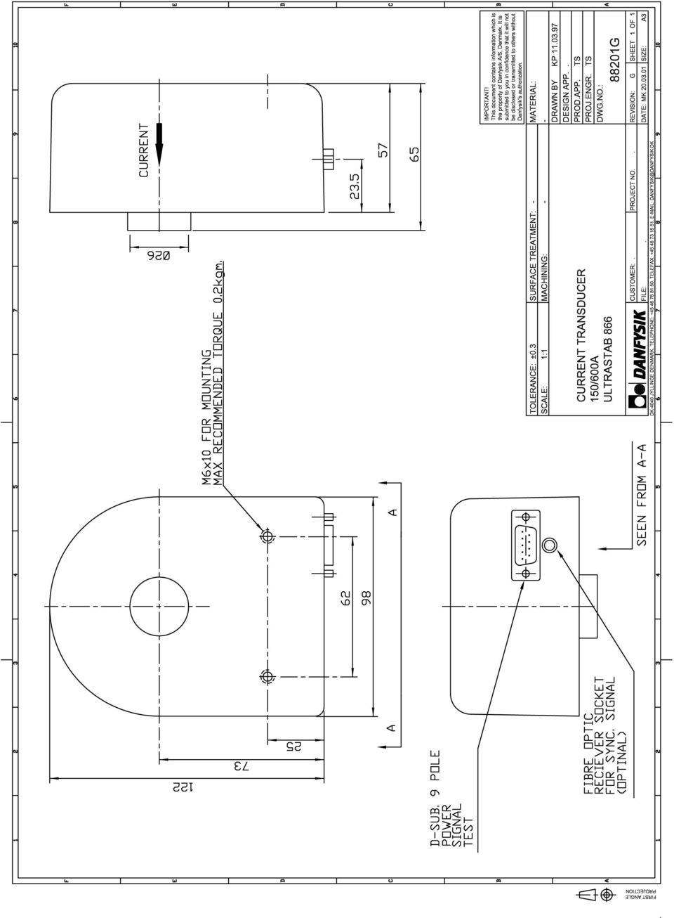
16 BASIC SPECIFICATION FOR A SINGLE CHANNEL Channel separation at max nominal current, and slew rate at 40kA/ms Bandwidth (small signal 0.5%) 3 db Busbar free zone to be within linearity specification: Cylinder shape (diameter x length) Test voltage transducer head 0.05% / 66dB DC to 100 khz ø 150 x 150 mm 5 kv AC (RMS) Cable length electronics measuring head 5 m Operating temperature C Storage temperature 0 60 C Input power requirement Emission complying standard Immunity complying standard V, AC, 50/60Hz max. 100V A EN EN Operating humidity 20 80% Mechanical dimensions: A. Electronics Weight 483 x 88 x 250 mm Approx. 4 kg B. Transducer (dwg ) Hole for conductor Weight (each transducer) 122 x 98 x 65 mm ø 26 mm 1 kg All ppm figures refer to max. output. Specifications are subject to change without notice. *) Optional output data: The 866R can be delivered factory programmed for: ± 200mA / ± 1V at 300A primary current - or ± 100mA / ± 1V at 150A primary current - or ± 50mA / ± 1V at 75A primary current DANFYSIK A/S DK-4040 Jyllinge Denmark Tel.: Fax: Web: sales@danfysik.dk spec866r_09a03.doc 09A03

17

18

19
20

21 D D PSU1 +15V C Main PCB Channel 1 Channel 2 Channel 3 Channel 4 Channel 5 Channel 6 C PSU1-17V Filter VOM module VOM module VOM module VOM module VOM module VOM module B B Power Status/Interlock VAC 50/60 Hz. A A 5 4 Ultrastab 866R main blockdiagram SCHEMATIC FILE. T:\PROJEKTER-IGANG\PC STYRET TEST SYSTEM\TEST BOX\866R MAIN SCHEMATIC.DSN CUSTM ORDER NO DRAWN BY. JB DESIGN APP. PROD APP. PROJ. ENGR. DWG.NO.: MØLLEHAVEN 31 DK-4040 JYLLINGE DENMARK TELEPHONE: TELEFAX: DANFYSIK@DANFYSIK.DK (820) REV. SHEET. 1 OF 1 Modified. Friday, September 26, :22:39 Created. Wednesday, September 24, :17: SI ZE A4 5 Uout +/- 1V Iout + Iout - Transducer Uout +/- 1V Iout + Iout - Transducer Uout +/- 1V Iout + Iout - Transducer Uout +/- 1V Iout + Iout - Transducer Uout +/- 1V Iout + Iout - Transducer Uout +/- 1V Iout + Iout - Transducer LED Power LED Normal operation LED 866 Powered LED Normal operation LED 866 Powered LED Normal operation LED 866 Powered LED Normal operation LED 866 Powered LED Normal operation LED 866 Powered LED Normal operation LED 866 Powered
22
23 ULTRASTAB 866 R CURRENT TRANSDUCER SYSTEM CONTROL POWER NORMAL OPERATION NORMAL OPERATION NORMAL OPERATION NORMAL OPERATION NORMAL OPERATION NORMAL OPERATION 866 POWERED 866 POWERED 866 POWERED 866 POWERED 866 POWERED 866 POWERED DANFYSIK R A B C D Not in use A B C D Not in use A C B D Not in use C A B D Not in use SN: 100XXXXX Programming Transducer type Primary current Output current A 600A 400mA C A B D C A B 300A 200mA B C 150A 100mA D 75A 50mA D B 400A 200mA Not in use Not in use C 200A 100mA D 100A 50mA GND ±1V ANALOG OUTPUT ±I OUT ±1V ±1V ANALOG OUTPUT ANALOG OUTPUT ±I OUT ±I OUT ±1V ±1V ANALOG OUTPUT ANALOG OUTPUT ±I OUT ±I OUT ±1V ANALOG OUTPUT ±I OUT WARNING! Do not connect or disconnect Analog output and/or Transducer head with power on POWER V AC/50-60Hz CHASSIS TRANSDUCER 6 TRANSDUCER 5 TRANSDUCER 4 TRANSDUCER 3 TRANSDUCER 2 TRANSDUCER 1 DANFYSIK UltraStab 866R Part No: Serie No: STATUS/INTERLOCK
24
25
26
ABB Drives. User s Manual. Pulse Encoder Interface Module RTAC-01
 ABB Drives User s Manual Pulse Encoder Interface Module RTAC-0 Pulse Encoder Interface Module RTAC-0 User s Manual 3AFE 64486853 REV A EN EFFECTIVE:.5.00 00 ABB Oy. All Rights Reserved. Safety instructions
DUAL%CHANNEL BROADBAND%LINEAR%AMPLIFIER Model&A800D
 ELECTRONICS AB DUAL%CHANNEL BROADBAND%LINEAR%AMPLIFIER Model&A800D & HIGH&VOLTAGE& FIXED&GAIN& BROADBAND & 800Vpp&60mA& 100x& DC&to&ca&200&kHz & LOW&OUTPUT&IMPEDANCE& HIGH&SLEW&RATE &
BroadBand PowerShield. User Manual
 BroadBand PowerShield User Manual 990-0375G 12/2006 Chapter 1 General Information The PowerShield provides a power source for broadband telephony and other DC applications. Safety This Safety Guide contains
Instructions A622 100 Amp AC/DC Current Probe 070-8883-03
 Instructions A622 100 Amp AC/DC Current Probe 070-8883-03 Revision A www.tektronix.com 070888303 Copyright Tektronix, Inc. All rights reserved. Tektronix products are covered by U.S. and foreign patents,
DS 600. A contact free flux gate based current measurement sensor 600A rms
 DS 600 A contact free flux gate based current measurement sensor 600A rms DS 600 is member of the small housing sensor family. The family includes a 200A and a 600A version. 600A rms - 900A peak Maximum
RI-215A Operator s Manual. Part Number: 71-0045RK Revision 0 Released: 10/3/05
 RI-215A Operator s Manual Part Number: 71-0045RK Revision 0 Released: 10/3/05 Warranty RKI Instruments, Inc., warrants gas alarm equipment sold by us to be free from defects in materials and workmanship,
Contents. Document information
 User Manual Contents Document information... 2 Introduction... 3 Warnings... 3 Manufacturer... 3 Description... Installation... Configuration... Troubleshooting...11 Technical data...12 Device Scope: PCB
Isolated AC Sine Wave Input 3B42 / 3B43 / 3B44 FEATURES APPLICATIONS PRODUCT OVERVIEW FUNCTIONAL BLOCK DIAGRAM
 Isolated AC Sine Wave Input 3B42 / 3B43 / 3B44 FEATURES AC averaging technique used to rectify, amplify, and filter 50 Hz to 400 Hz sine-wave signals. Accepts inputs of between 20 mv to 550 V rms to give
THERMAL ANEMOMETRY ELECTRONICS, SOFTWARE AND ACCESSORIES
 TSI and TSI logo are registered trademarks of TSI Incorporated. SmartTune is a trademark of TSI Incorporated. THERMAL ANEMOMETRY ELECTRONICS, SOFTWARE AND ACCESSORIES IFA 300 Constant Temperature Anemometry
PS 155 WIRELESS INTERCOM USER MANUAL
 PS 155 INTERFACE TO SIMPLEX WIRELESS INTERCOM USER MANUAL Issue 2011 ASL Intercom BV DESIGNED AND MANUFACTURED BY: ASL INTERCOM BV ZONNEBAAN 42 3542 EG UTRECHT THE NETHERLANDS PHONE: +31 (0)30 2411901
GAE953 Electrical Alarm Unit 19" with Indicator
 Master Instruction 08.95 MI EIO2211 A-(en) GAE953 Electrical Alarm Unit 19" with Indicator The electrical alarm unit GAE953 gives a signal when one or two set alarm values have been exceeded. Input signals
Contents. Safety Warnings... 1
 Contents Safety Warnings... 1 Unpacking the GQ600... 1 Introduction... 2 GQ600 Filter Characteristics... 2 1/3 Octave Centre Frequencies... 4 Front Panel Functions... 5 Rear Panel Functions... 6 Specifications...
RISH CON - Hz. Salient Features : Application : Product Features: FREQUENCY TRANSDUCER
 Application : The RISH CON - Hz transducer is used for frequency measurement. The output signal is proportional to measured frequency and is either load independent DC Current or load independent DC Voltage.
Product Information Sheet UH28CS-12kV Hi Pot Tester
 Product Information Sheet UH28CS-12kV ETL Prüftechnik GmbH Telefon: +49 711 83 99 39-0 E-Mail: info@etl-prueftechnik.de Carl-Peters-Straße 23 D-70825 Korntal-Münchingen Telefax: +49 711 83 99 39-9 Internet:
IRT Eurocard. Types DAX-3200
 I R T Electronics Pty Ltd A.B.N. 35 000 832 575 26 Hotham Parade, ARTARMON N.S.W. 2064 AUSTRALIA National: Phone: (02) 9489 3744 Fax: (02) 9439 7439 International: +61 2 9439 3744 +61 2 9439 7439 Email:
Differential Charge Amplifier
 Electronics Differential Type 58A... The differential charge amplifier is used for signal conversion of piezoelectric sensors with differential output. Executions Aluminum die-cast enclosure (IP64) Plastic
How To Test A Power Distribution Unit
 PDUAC3U SERIES AC POWER DISTRIBUTIO UITS www.unipowerco.com Manual o. PDUAC3U-1 pduac3u-man-rev1-1015.indd 2015 UIPOWER LLC All Rights Reserved ORTH AMERICA 3900 Coral Ridge Drive, Coral Springs, Florida
The table below lists the symbols used on the Clamp and/or in this manual. Important Information. See manual.
 i800 AC Current Clamp Instruction Sheet Introduction The i800 AC Current Clamp, the Clamp, has been designed for use with multimeters, recorders, power analyzers, safety testers, etc., for accurate non-intrusive
Quick Connect. quick - simple - efficient. www.g-mw.de
 Quick Connect quick - simple - efficient www.g-mw.de Phone: +49 9103 7129-0 Fax: +49 9103 7129-207 Innovative connection technology to plug three single-phase current transformers to multifunctional power
Advantium 2 Plus Alarm
 ADI 9510-B Advantium 2 Plus Alarm INSTALLATION AND OPERATING INSTRUCTIONS Carefully Read These Instructions Before Operating Carefully Read These Controls Corporation of America 1501 Harpers Road Virginia
CX Zoner Installation & User Guide
 CX Zoner Installation & User Guide Cloud Electronics Limited 140 Staniforth Road, Sheffield, S9 3HF England Tel +44 (0)114 244 7051 Fax +44 (0)114 242 5462 e-mail info@cloud.co.uk web site http://www.cloud.co.uk
Research RF Sputtering Packages
 Research RF Sputtering Packages Shown with 3" Polaris Adjustable Position Source with Tilt and Shutter 300 or 600 Watt Low Cost Packages for Those With Limited Budgets Desiring Full Capability 13.56 MHz
Physical Specifications (Custom design available.)
") Helmholtz Coils A useful laboratory technique for getting a fairly uniform magnetic field, is to use a pair of circular coils on a common axis with equal currents flowing in the same sense. For a given
Helmholtz Coils A useful laboratory technique for getting a fairly uniform magnetic field, is to use a pair of circular coils on a common axis with equal currents flowing in the same sense. For a given
AIR QUALITY SURVEILLANCE BRANCH ACCEPTANCE TEST PROCEDURE (ATP) FOR. Teledyne Advanced Pollution Instruments Model 400 E Ozone Analyzer AQSB ATP 002
 FOR. Teledyne Advanced Pollution Instruments Model 400 E Ozone Analyzer AQSB ATP 002") AIR QUALITY SURVEILLANCE BRANCH ACCEPTANCE TEST PROCEDURE (ATP) FOR Teledyne Advanced Pollution Instruments Model 400 E Ozone Analyzer AQSB ATP 002 First Edition MONITORING AND LABORATORY DIVISION August
AIR QUALITY SURVEILLANCE BRANCH ACCEPTANCE TEST PROCEDURE (ATP) FOR Teledyne Advanced Pollution Instruments Model 400 E Ozone Analyzer AQSB ATP 002 First Edition MONITORING AND LABORATORY DIVISION August
AMU PROFESSIONAL VIDEO AND AUDIO MONITORING UNIT OPERATOR'S HANDBOOK ISSUE A3
 AMU PROFESSIONAL VIDEO AND AUDIO MONITORING UNIT OPERATOR'S HANDBOOK ISSUE A3 2008 Hamlet Video International Ltd. All rights reserved This handbook contains proprietary information of Hamlet Video International
Modular I/O System Analog and Digital Interface Modules
 OPERATING INSTRUCTIONS Modular I/O System Analog and Digital Interface Modules Installation Operation Maintenance Document Information Document ID Title: Operating Instructions Modular I/O System Part
ATS Overhead Table Shelf System INSTRUCTION MANUAL
 ATS Overhead Table Shelf System INSTRUCTION MANUAL ATS Overhead Table Shelf System Instruction Manual Warranty Newport Corporation warrants this product to be free of defects in material and workmanship
ABB Drives. User s Manual HTL Encoder Interface FEN-31
 ABB Drives User s Manual HTL Encoder Interface FEN-31 HTL Encoder Interface FEN-31 User s Manual 3AUA0000031044 Rev B EN EFFECTIVE: 2010-04-06 2010 ABB Oy. All Rights Reserved. 5 Safety instructions
Model SRMD Setra Remote Monitoring Display
 Model SRMD Setra Remote Monitoring Display 1.0 GENERAL INFORMATION Thank you for purchasing the Setra Remote Monitoring Display (SRMD). The SRMD is a digital panel meter with a bright 1 LED display for
PERF10 Rubidium Atomic Clock
 Owner s Manual Audio Stanford Research Systems Revision 1.0 February, 2011 2 Certification Stanford Research Systems certifies that this product met its published specifications at the time of shipment.
Features. Display. Measurements. Intelligent. Accuracy. Models. Installation DEIF A/S. Multi-instrument 4921210109D
 7000/7000C/7020 Multi-instrument 4921210109D Features Measurements All 3-phase AC measurements True RMS Replaces analogue meters Demand on each phase current Accuracy U, I and F class 0.5 Other values
MODEL 1211 CURRENT PREAMPLEFIER
 MODEL 1211 CURRENT PREAMPLEFIER Phone: (607)539-1108 Email: info@dlinstruments.com www.dlinstruments.com The Model 1211 Current Preamplifier was designed to provide all of the features required of a modern
T0118 T2118 T3118. Instruction Manual
 Programmable indoor transmitter of temperature T0118 Programmable indoor transmitter of atmospheric pressure T2118 Programmable indoor transmitter of temperature, relative humidity and other derived humidity
SETUP GUIDE SNMP ALARM ADAPTOR COMPATIBLE WITH SIGMA, RADIAN, TPCMQ, auro-he & BLUEstreak POWER SHELVES
 SNMP ALARM ADAPTOR COMPATIBLE WITH SIGMA, RADIAN, TPCMQ, auro-he & BLUEstreak POWER SHELVES www.unipowerco.com 2014 UNIPOWER LLC All Rights Reserved NORTH AMERICA 3900 Coral Ridge Drive, Coral Springs,
PEDAL POWER. User s Manual
 PEDAL POWER AC User s Manual Copyright 2005-2008 by Digital Music Corporation. This publication is protected by copyright and all rights are reserved. No part of it may be reproduced or transmitted by
User's Guide. Integrating Sound Level Datalogger. Model 407780. Introduction
 User's Guide 99 Washington Street Melrose, MA 02176 Phone 781-665-1400 Toll Free 1-800-517-8431 Visit us at www.testequipmentdepot.com Back to the Extech 407780 Product Page Integrating Sound Level Datalogger
FREQUENCY RESPONSE ANALYZERS
 FREQUENCY RESPONSE ANALYZERS Dynamic Response Analyzers Servo analyzers When you need to stabilize feedback loops to measure hardware characteristics to measure system response BAFCO, INC. 717 Mearns Road
HSP GmbH Zum Handwerkerhof 2 90530 Wendelstein Tel. 09129 / 2852-0 Fax: 09129 / 2852-11 Web: www.hsshsp.de EMAIL: HSP@hsshsp.de NTG-3000.
 NTG-3000 Transducer Data Sheet Document Version 2.8 Page 1 of 10 Versions / Revisions: Document Creation Author Description version date 2.0 2012-07-25 P. Compensis First official version 2.1 2012-08-24
APG-XT APG-HPD. Operating Manual. Internal APG (Analog Programming) Interface for XT/HPD Series Programmable DC Power Supply
 Interface for XT/HPD Series Programmable DC Power Supply") APG-XT APG-HPD Operating Manual Internal APG (Analog Programming) Interface for XT/HPD Series Programmable DC Power Supply Operating Manual for Internal APG (Analog Programming) Interface for XT 60 Watt
APG-XT APG-HPD Operating Manual Internal APG (Analog Programming) Interface for XT/HPD Series Programmable DC Power Supply Operating Manual for Internal APG (Analog Programming) Interface for XT 60 Watt
IRT Eurocard. Type DAX-3206. Audio Extractor for 270 Mb/s SDI
 I R T Electronics Pty Ltd A.B.N. 35 000 832 575 26 Hotham Parade, ARTARMON N.S.W. 2064 AUSTRALIA National: Phone: (02) 9439 3744 Fax: (02) 9439 7439 International: 61 2 9439 3744 61 2 9439 7439 Email:
Series AMLDL-Z Up to 1000mA LED Driver
 FEATURES: Click on Series name for product info on aimtec.com Series Up to ma LED Driver Models Single output Model Input Voltage (V) Step Down DC/DC LED driver Operating Temperature range 4ºC to 85ºC
Amplified High Speed Fiber Photodetectors
 Amplified High Speed Fiber Photodetectors User Guide (800)697-6782 sales@eotech.com www.eotech.com Page 1 of 7 EOT AMPLIFIED HIGH SPEED FIBER PHOTODETECTOR USER S GUIDE Thank you for purchasing your Amplified
GREISINGER electronic GmbH
 T38.0.0X.6C-03 CO2 - Transmitter Operating Manual GT10 - CO2-1R GREISINGER electronic GmbH D - 93128 Regenstauf, Hans-Sachs-Straße 26 Tel.: +49 9402 / 9383-0, Fax: +49 9402 / 9383-33, email: info@greisinger.de
14.5GHZ 2.2KW CW GENERATOR. GKP 22KP 14.5GHz WR62 3x400V
 14.5GHZ 2.2KW CW GENERATOR GKP 22KP 14.5GHz WR62 3x400V UTILIZATION OF GKP 22KP GENERATOR With its characteristics of power stability whatever the load, very fast response time at a pulse, low ripple,
USER MANUAL. Model 6103 3U ForeFront Alarm Card SALES OFFICE (301) 975-1000 TECHNICAL SUPPORT (301) 975-1007. An ISO-9001 Certified Company
 975-1000 TECHNICAL SUPPORT (301) 975-1007. An ISO-9001 Certified Company") USER MANUAL Model 6103 3U ForeFront Alarm Card An ISO-9001 Certified Company Part# 07M6103 Doc# 123011U Rev. A Revised 7/15/03 SALES OFFICE (301) 975-1000 TECHNICAL SUPPORT (301) 975-1007 CONTENTS 1.0
USER MANUAL Model 6103 3U ForeFront Alarm Card An ISO-9001 Certified Company Part# 07M6103 Doc# 123011U Rev. A Revised 7/15/03 SALES OFFICE (301) 975-1000 TECHNICAL SUPPORT (301) 975-1007 CONTENTS 1.0
EC4.8. BalancedReferencePreamplifier. Owner smanual ENG
 EC4.8 BalancedReferencePreamplifier Owner smanual ENG Unpacking the EC 4.8 Immediately upon receipt of the EC 4.8, inspect the carton for possible damage during shipment. The carton and packaging have
Electronic Pressure Switch EDS 300
 Electronic Pressure Switch EDS 300 User manual Page 2 of 16 Content 1. Functions of the EDS 300...3 2. Mounting...3 3. Operating keys on the membrane keypad...4 4. Digital display...4 5. Output function...5
User manual Rev. 1.2 (17/04/2015)
") User manual Rev. 1.2 (17/04/2015) CompactPCI Serial power supply CompactPCI Serial power supply (for illustration only) CompactPCI Serial is a new standard that supports the fast serial protocols PCI Express,
User manual Rev. 1.2 (17/04/2015) CompactPCI Serial power supply CompactPCI Serial power supply (for illustration only) CompactPCI Serial is a new standard that supports the fast serial protocols PCI Express,
TECHNICAL DATASHEET #TD1404AX PWM CONTROLLED SOLENOID DRIVER
 TECHNICAL DATASHEET #TD1404AX PWM CONTROLLED SOLENOID DRIVER (PWM Input, 1.2A or 2A Output, Metal Box or PCB) PCB Board - P/N: PWMC-PCB-2A, PWMC-PCB-1.2A Packaged Driver (metal box with 1.5 m (5 ft.) cable)
Technical Note Series
 Technical Note Series SKIN CONDUCTANCE SENSOR (SA9309M) S TN0 0 0 8-0 0 S k i n C o n d u c t a n c e S e n s o r Page 2 IMPORTANT OPERATION INFORMATION WARNING Type BF Equipment Internally powered equipment
SECTION 28 23 23 VIDEO SURVEILLANCE SYSTEMS INFRASTRUCTURE
 PART 1 - GENERAL 1.1 SUMMARY SECTION 28 23 23 VIDEO SURVEILLANCE SYSTEMS INFRASTRUCTURE A. Section Includes 1. Video Surveillance Systems Infrastructure B. Related Sections 1. Section [28 23 16 Video Surveillance
Agilent N8973A, N8974A, N8975A NFA Series Noise Figure Analyzers. Data Sheet
 Agilent N8973A, N8974A, N8975A NFA Series Noise Figure Analyzers Data Sheet Specifications Specifications are only valid for the stated operating frequency, and apply over 0 C to +55 C unless otherwise
High Voltage Power Supplies
 Source voltages up to 5kV and 10kV 1µA current measurement resolution Multi-channel programmable DC power supplies Low noise for precision sourcing and sensitive measurements; selectable filters reduce
Process modules Digital input PMI for 24 V DC inputs for 120 V AC inputs
 E031026 000823 Process modules Digital input PMI for inputs for 120 V AC inputs PMI Input E4, E5, GND L- PMI 120 V AC Input E4, E5, Common C E6, E7, GND L- E6, E7, Common C LEDs for the inputs operation
ADM1TE 5/30A DIN rail single phase two wire energy meter
 ADMTE 5/30A DIN rail single phase two wire energy meter. Safety instruction.2 Foreword.3 Performance criteria.4 Specifications.5 Basic errors.6 Description.7 Dimensions.8 Installation.9 Operating.0 Troubleshooting.
Rack mounted telephone- and leased line modem for industrial applications
 Rack mounted telephone- and leased line modem for industrial applications TR-6 Rack modem for industrial PSTNand /-wire leased line applications The TR-6 is an analogue V. 9 -rack PSTN modem as well as
USER MANUAL. Kramer Electronics, Ltd. Models:
 Kramer Electronics, Ltd. USER MANUAL Models: VP-200N, 1:2 High Resolution XGA DA VP-300N, 1:3 High Resolution XGA DA VP-400N, 1:4 High Resolution XGA DA Contents Contents 1 Introduction 1 2 Getting Started
User Manual. CFG253 3 MHz Function Generator 070-8362-04
 User Manual CFG253 3 MHz Function Generator 070-8362-04 Copyright Tektronix, Inc. 1993. All rights reserved. Tektronix products are covered by U.S. and foreign patents, issued and pending. Information
USER MANUAL. 914 Power Amplifier MODEL: P/N: 2900-300280 Rev 1
 KRAMER ELECTRONICS LTD. USER MANUAL MODEL: 914 Power Amplifier P/N: 2900-300280 Rev 1 Contents 1 Introduction 1 2 Getting Started 2 2.1 Achieving the Best Performance 2 3 Overview 3 3.1 Energy Star 3
Current Probes. User Manual
 Current Probes User Manual ETS-Lindgren L.P. reserves the right to make changes to any product described herein in order to improve function, design, or for any other reason. Nothing contained herein shall
QUICK START GUIDE FOR DEMONSTRATION CIRCUIT 956 24-BIT DIFFERENTIAL ADC WITH I2C LTC2485 DESCRIPTION
 LTC2485 DESCRIPTION Demonstration circuit 956 features the LTC2485, a 24-Bit high performance Σ analog-to-digital converter (ADC). The LTC2485 features 2ppm linearity, 0.5µV offset, and 600nV RMS noise.
Duct Humidity Transmitter
 SDC-H Duct Humidity Transmitter Features Replaceable sensor element Humidity measurement for air ducts Minimum and maximum value memory 0 0V, 0 0mA or 0V, 4 0mA measuring signals selectable with jumpers
AC/DC Power Modules C B. TML Series, 20 & 40 Watt. Features. 20 Watt Models
 TML Series, 0 & 0 Watt Features C B Scheme LVD UL 090- Encapsulated power supplies with increased power density Replaces TML and TML 0 series PCB mount or chassis mount with screw terminals Single, dual
Keysight N4877A Clock Data Recovery and Demultiplexer 1:2
 Keysight N4877A Clock Data Recovery and Demultiplexer 1:2 Getting Started Getting Started with the Keysight N4877A Clock Data Recovery and Demultiplexer 1:2 You only need a few minutes to get started
T7560A,B,C Digital Wall Module
 T7560A,B,C Digital Wall Module HONEYWELL EXCEL 5000 OPEN SYSTEM BEFORE INSTALLATION All wiring must comply with local electrical codes and ordinances or as specified on installation wiring diagrams. Digital
Option field bus: without bus with profibus DP. Design-Index (Subject to change)
") Amplifier / controller cards ED1 Digital amplifier / controller card ED1 for 1 or 2 proportional solenoids 4 analogue inputs, of which 2 for differential inputs 8 digital inputs Card setting via PC, multi-function
Amplifier / controller cards ED1 Digital amplifier / controller card ED1 for 1 or 2 proportional solenoids 4 analogue inputs, of which 2 for differential inputs 8 digital inputs Card setting via PC, multi-function
Model 3000-51 20 SPDT Relays 90401460
 Model 3000-51 20 SPDT Relays 90401460 Page 1 All technical data and specifications in this publication are subject to change without prior notice and do not represent a commitment on the part of Giga-tronics,
DRTS 33. The new generation of advanced test equipments for Relays, Energy meters, Transducers and Power quality meters
 The new generation of advanced test equipments for Relays, Energy meters, Transducers and Power quality meters Testing all relay technologies: electromechanical, solid state, numerical and IEC61850 Manual
HERZ-Thermal Actuators
 HERZ-Thermal Actuators Data Sheet 7708-7990, Issue 1011 Dimensions in mm 1 7710 00 1 7710 01 1 7711 18 1 7710 80 1 7710 81 1 7711 80 1 7711 81 1 7990 00 1 7980 00 1 7708 11 1 7708 10 1 7708 23 1 7709 01
Analog Servo Drive 25A8
 Description Power Range NOTE: This product has been replaced by the AxCent family of servo drives. Please visit our website at www.a-m-c.com or contact us for replacement model information and retrofit
Agilent 87421A/87422A Power Supply
 Agilent 87421A/87422A Power Supply Technical Overview Designed specifically for Agilent Technologies microwave system amplifiers Bias cable permits remote placement Compact size for easy system integration
MPC 4. Machinery Protection Card Type MPC 4 FEATURES. Continuous on-line Machinery Protection Card
 Machinery Protection Card Type FEATURES Continuous on-line Machinery Protection Card Real-time measurement and monitoring using state-of-the-art DSP techniques Fully VME-compatible slave interface Fully
Congratulations! Thank you!
 TM-47 ORDERCODE D1370 Congratulations! You have bought a great, innovative product from DAP Audio. The DAP Audio Microphone range brings excitement to any venue. Whether you want simple plug-&-play action
USER MANUAL. Kramer Electronics, Ltd. Models:
 Kramer Electronics, Ltd. USER MANUAL Models: VP-200N, 1:2 High Resolution XGA DA VP-300N, 1:3 High Resolution XGA DA VP-400N, 1:4 High Resolution XGA DA Contents Contents 1 Introduction 1 2 Getting Started
Series 6000 Torque measured metal bellow coupling
 Properties Free of float metal bellow coupling with integrated torque measurement Non-contact measurement system, high robustness High torsional stiffness Limited torque of inertia Performance Measurement
How To Install A Power Supply (Uplast) With A Battery Pack
 With A Battery Pack") APC Smart-UPS RT SURTA48XLBP/SURTA48XLBPJ External Battery Pack User Manual Introduction/Before Installation About this Manual The APC Smart-UPS RT external battery pack (SURTA48XLBP or SURTA48XLBPJ) connects
APC Smart-UPS RT SURTA48XLBP/SURTA48XLBPJ External Battery Pack User Manual Introduction/Before Installation About this Manual The APC Smart-UPS RT external battery pack (SURTA48XLBP or SURTA48XLBPJ) connects
HP UPS R1500 Generation 3
 HP UPS R1500 Generation 3 Installation Instructions Part Number 650952-001 NOTE: The rating label on the device provides the class (A or B) of the equipment. Class B devices have a Federal Communications
PagePac PAGEPAL V-5335700
 PagePac Issue 3 by PAGEPAL V-5335700 INTRODUCTION The PagePal unit interfaces most telephone systems (PBX, KTS, Centrex) to virtually any public address audio system. In addition, PagePal furnishes inputs
DRM75A 230V 20/100A DIN rail single phase two wire energy meter
 DRM75A 230V 20/100A DIN rail single phase two wire energy meter 1.1 Safety instruction 1.2 Foreword 1.3 Performance criteria 1.4 Specifications 1.5 Basic errors 1.6 Description 1.7 Dimensions 1.8 Installation
GT Sensors Precision Gear Tooth and Encoder Sensors
 GT Sensors Precision Gear Tooth and Encoder Sensors NVE s GT Sensor products are based on a Low Hysteresis GMR sensor material and are designed for use in industrial speed applications where magnetic detection
www.kem-kueppers.com info@kem-kueppers.com Certified according to DIN EN ISO 9001 Technical Datasheet C-Flow Coriolis Mass Flow Meter
 www.kem-kueppers.com info@kem-kueppers.com Certified according to DIN EN ISO 9001 Technical Datasheet C-Flow Coriolis Mass Flow Meter Description The coriolis mass flow meters measure simultaneously mass
Telephone- and leased line modem for industrial applications TD-36
 Telephone- and leased line modem for industrial applications TD-36 Modem for industrial PSTN- and leased line applications The TD-36 is an analogue V.34 PSTN modem as well as an industrial 2-wire leased
For a complete explanation of all the functions and configurations available please refer to the SC6006: Manual of operation.
 PRELIMINARY TECHNICAL INFORMATION Three-phase Digital SCR Firing Board HIGHLIGHTS - Up to 480 V AC input supply voltage - Up to 700 V AC sync input - DSP controlled - Digital or analog input signaling
HIH-4000 Series Humidity Sensors
 HIH-4000 Series Humidity Sensors DESCRIPTION The HIH-4000 Series Humidity Sensors are designed specifically for high volume OEM (Original Equipment Manufacturer) users. Direct input to a controller or
zseries 18-Slot Chassis 18-Slot 3U PXI Express Chassis with AC Up to 8 GB/s
 TECHNICAL SPECIFICATIONS zseries 18-Slot Chassis 18-Slot 3U PXI Express Chassis with AC Up to 8 GB/s 2015 LitePoint, A Teradyne Company. All rights reserved. The LitePoint zseries 18-slot chassis is an
F2400 FOM II Series Fiber Optic Modem Technical Manual
 F2400 FOM II Series Fiber Optic Modem Technical Manual T1 Revision B Copyright April 2003 VERSITRON, Inc. 83 Albe Drive / Suite C Newark, DE 19702 www.versitron.com A030430283T PROPRIETARY DATA All data
Differential Pressure Sensors for air and non-corrosive gases, with calibration certificate
 1 919 1919P01 1919P03 QBM65/C, QBM75-1U/C Differential Pressure Sensors for air and non-corrosive gases, with calibration certificate QBM751-1/C QBM65/C QBM75/C Highly accurate measurements with calibration
ALARM ANNUNCIATOR ME - 3010 INSTRUCTION MANUAL
 ALARM ANNUNCIATOR ME - 3010 INSTRUCTION MANUAL INTRODUCTION... 2.. TECHNICAL DATA... 3 ACCESSORIES... 5. INSTALLATION... 7 OPERATION... 12. TECHNICAL INFORMATION... 13 MAINTENANCE... 14. CONFIGURATIONS...
INSTRUCTION MANUAL for UNIBLITZ MODEL DM412 SHUTTER DRIVE MODULE
 INSTRUCTION MANUAL for UNIBLITZ MODEL DM412 SHUTTER DRIVE MODULE VINCENT ASSOCIATES 803 LINDEN AVE. ROCHESTER, NEW YORK 14625 SERVICE/ORDERS (800) 828-6972 In NY State (585) 385-5930 Fax (585) 385-6004
Multi-Protocol decoder 76 200 with Load regulation
 Multi-Protocol decoder 76 2 with Load regulation For locomotives with universal motors on digital layouts operating in the DCC and Motorola data format. Features 76 2 Load regulated multi-protocol decoder
MINI MCR-SL-R-UI(-SP)
") Resistance/potiposition transducer INTERFACE Data Sheet 0807_en_05 Description PHOENIX CONTACT - 0/008 Features The slim MINI MCR-SL-R-UI... potiposition transducer has a width of only 6. mm and converts
Resistance/potiposition transducer INTERFACE Data Sheet 0807_en_05 Description PHOENIX CONTACT - 0/008 Features The slim MINI MCR-SL-R-UI... potiposition transducer has a width of only 6. mm and converts
Current Monitoring Kit
 Current Monitoring Kit QUICK START GUIDE DO090-6 CONTENTS Issues: 1) 2.10.02 WP A4 format 2) 2.10.02 Added safety warning 3) 17.3.06 Word A5 format. S1: Removed relay modules. S2: Added MI010. S4.1: added
JUMPFLEX 857 Series. 0...20 ma 2...10 V. 4...20 ma. Transducers / Relay and Optocoupler Modules
 0888-0172/0002-3601 JUMPFLEX 857 Series 2.0 E 12/08 Printed in Germany Subject to design changes 2...10 V 0...20 ma 4...20 ma WAGO Kontakttechnik GmbH & Co. KG Postfach 2880 32385 Minden Hansastraße 27
Voltage Regulator SPAU 341 C. Product Guide
 Issued: July 1998 Status: Updated Version: D/25.04.2006 Data subject to change without notice Features Comprehensive voltage regulation for power transformers with on-load tapchangers in distribution substations
TELIKOU Intercom System. MS-500(4+1 channel) Main Station Instruction Manual
 Main Station Instruction Manual") TELIKOU Intercom System MS-500(4+1 channel) Main Station Instruction Manual TELIKOU Systems All Rights Reserved While TELIKOU makes every attempt to maintain the accuracy of the information contained in
TELIKOU Intercom System MS-500(4+1 channel) Main Station Instruction Manual TELIKOU Systems All Rights Reserved While TELIKOU makes every attempt to maintain the accuracy of the information contained in
T-SERIES INDUSTRIAL INCLINOMETER ANALOG INTERFACE
 T-SERIES INDUSTRIAL INCLINOMETER ANALOG INTERFACE T-Series industrial inclinometers are compact high performance sensors used to determine inclination in roll and pitch axes with excellent precision and
CAUTION! THE 7I29 USES VOLTAGE AND POWER LEVELS THAT REPRESENT A HAZARD TO LIFE AND LIMB.
 7I29 MANUAL Rev 1.5 CAUTION! THE 7I29 USES VOLTAGE AND POWER LEVELS THAT REPRESENT A HAZARD TO LIFE AND LIMB. THE 7I29 IS INTENDED FOR USE BY OEMS THAT WILL INTEGRATE IT INTO A SYSTEM WITH INTERLOCKS AND
PSP3. Stereo M/S preamplifier. User manual
 PSP3 Stereo M/S preamplifier User manual AETA AUDIO 361, avenue du Général de Gaulle 92140 Clamart FRANCE Tél. +33 (0)1 41361212 Fax +33 (0)1 41361213 Telex 631178 Web : http://www.aetausa.com 55 000 020
LOXONE 12 Channel Amplifier
 LOXONE 12 Channel Amplifier Item no.: 200110 Thank you for purchasing the Loxone Twelve Channel Amplifier. The versatility of the Amplifier makes it the perfect choice for almost every type of custom multi-room
MCR1900 Media Converter 19-Slot Chassis
 MCR1900 Media Converter 19-Slot Chassis Installation Guide Part #5500304-11 Copyright Statement This document must not be reproduced in any way whatsoever, either printed or electronically, without the