SERVICE MANUAL GENERATORS NGK-2900H, NGK-4300H, NGK-6000H, NGK-7000H
|
|
|
- Annabella Merritt
- 8 years ago
- Views:
Transcription
1 SERVICE MANUAL GENERATORS NGK-2900H, NGK-4300H, NGK-6000H, NGK-7000H MMD Equipment Inc. 121 High Hill Road Swedesboro, NJ Tel: (800) Fax: (856)
 433-1382 Fax: (856) 467-5235 www.")
2 TABLE OF CONTENTS Safety Precautions 1 Specifications and Maintenance Schedule 2 Repair Questionnaire 3 Pre-Operation Checks 5 Starting Procedures 5 Using A.C. Electric Power 6 Stopping Procedures 7 Component Function GFCIs Circuit Breakers Idle Control Oil Sensor Wattage Information 8 Extension Cord Usage 9 Special Tools 10 Disassembly Instructions 11 Assembly Instructions 14 Troubleshooting Trees Engine Generator Detailed Troubleshooting Instructions 20 Test Values for Rotor, Stator, and Condensers 23 Full Power Switch and Circuit Breaker 25 Wiring Diagrams 26 Exploded Views of Generator 32 Torque Values 34

3 SAFETY PRECAUTIONS: Your safety is very important to us. While we cannot warn you about every possible hazard associated with operating your NAC portable generator, following the precautions listed below will assist you in operating your NAC generator safely. It is the operator s responsibility to be familiar with and to follow these important safety precautions. 1. Use extreme caution near gasoline and other flammables. Do not fill the fuel tank while the engine is running. WARNING! Do not smoke or use open flame near the generator. WARNING! Do not place flammables such as gasoline, oily rags, straw, trash, or matches near the generator. Take care not to spill fuel on the generator when re-fueling. If fuel is spilled, wipe it off and allow it to dry completely. 2. Operate the generator in a well-ventilated area. WARNING! Engine exhaust contains poisonous carbon monoxide gas, which can be fatal if inhaled. WARNING! Do not operate the generator indoors. If the generator must be operated indoors, the area MUST be well ventilated and EXTREME CAUTION must be taken to prevent inhalation of poisonous carbon monoxide gasses. Do not enclose the generator or cover it with a box. The engine and generator are air-cooled and may overheat if operated in an enclosed space. Keep the generator at least 3 feet (1 meter) from building walls and other equipment during operation. 3. Operate the generator on a dry, level surface. Operating the generator on an inclined surface may cause the splash lubrication system to operate improperly. The engine oil may flow away from the oil scraper and over the oil sensor. Therefore, the oil sensor will not stop the engine, even though there is no oil lubricating the engine components. This could cause the engine to seize and is not covered under warranty. 4. Always operate the generator in a dry environment. WARNING! Do not operate the generator in the rain, snow, or with wet hands. Severe electrical shock may occur. WARNING! Do not clean the generator with a pressure washer or any other water hose. Use a damp cloth to wipe down the generator, and be especially careful not to get water into the receptacles. WARNING! Ensure there is no electrical wiring underneath the generator frame. Vibration from the generator frame could wear through the wiring and cause sparks, fire, or shock hazard. 5. Additional safety information. WARNING! Do not connect the generator directly to household or other indoor wiring or to any commercial power line. This could cause fatal injuries to Utility Service Personnel or damage to the generator. A licensed electrician must install a Manual Transfer Switch to the main circuit breaker panel in order to use a generator for back-up power. Although NAC generators are neutral grounded to the frame and should provide more than adequate safety, use a grounding rod in accordance with local and OSHA safety requirements for optimum grounding. The muffler and engine crankcase are extremely hot during and after operation. Allow the engine adequate time to cool before touching the muffler or crankcase. 1

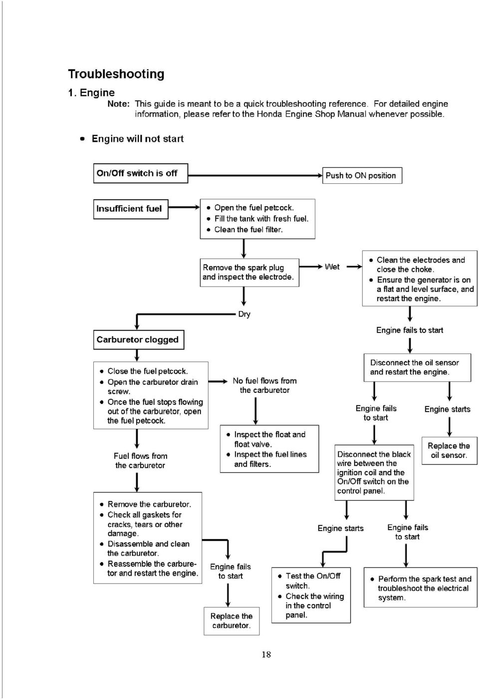
4 SPECIFICATIONS: Model NGK-2900H NGK-4300H NGK-6000H/E NGK-7000H/E Type Brushless, 2-pole, self-exciting, revolving field type Max AC output 2900W 4300W 6000W 7000W GENERATOR Rated AC output 2400W 3800W 5000W 6000W Rated voltage 120 V 120/240 V 120/240 V 120/240 V Rated current 20 A 31.7/15.9 A 41.7/20.8 A 50/25 A Phase Single Voltage regulation Condenser type Frequency 60 Hz Model Honda GX-160 Honda GX-240 Honda GX-340 Honda GX-390 Spec. number ED2 ED2 ED6 / EDD2 ED6 / EDD2 ENGINE Horsepower Fuel tank capacity 3.0 gal. 4.5 gal. 4.5 gal. 4.5 gal. Recommended fuel Unleaded gasoline (86 Octane or higher) Oil capacity 0.63 US qt US qt US qt US qt. Recommended oil SAE 10W-30 API SF or SG Starting system Recoil Recoil Recoil or electric* Recoil or electric* Dimensions (in.) (L x W x H) 22.4 x 17.3 x x 20.2 x x 21.3 x x 21.3 x 20.5 Dry weight 95 lbs. 150 lbs. 176 lbs. 191 lbs. * Electric start models are available as NGK-6000HE AND NGK-7000HE generators only. Recoil start models cannot be converted to electric start. **Use a GROUP 51 battery on electric start models. MAINTENANCE SCHEDULE: REGULAR SERIVCE PERIOD Perform at every indicated month or operating period, whichever comes first. Each use First month or 20 hrs. Every 3 months or 50 hrs. Every 6 months or 100 hrs. Every year or 300 hrs. Engine oil Check level Change Air cleaner Inspect Clean ℵ Fuel strainer cup Clean Spark plug Inspect-Clean Spark arrester Clean Valve clearance Check-Adjust Fuel tank and filter Clean Inspect Fuel line (Replace if necessary) * For detailed engine information, refer to the Honda Engine Shop Manual. Note: ℵ Service more frequently in dusty areas. 2 Every 2 years
 Oil capacity 0.63 US qt. 1.16 US qt.")
5 QUESTIONS TO ASK WHEN A CUSTOMER BRINGS A GENERATOR IN FOR SERVICE 1. What brand is the generator? 2. Which model? 3. What is the serial number of the generator? 4. Briefly describe the problem with the generator. 5. When did the failure occur? 6. Were there any tools connected to the generator when the failure occurred? Yes No a. Which tools were being used when the failure occurred? Tool #1 Quantity used: Tool #2 Quantity used: Brand: Model: Running amps (found on tool nameplate): Brand: Model: Running amps (found on tool nameplate): Tool #3 Quantity used: Brand: Model: Running amps (found on tool nameplate): Tool #4 Quantity used: Brand: Model: Running amps (found on tool nameplate): b. Which receptacle was the tool plugged into? Circle one i) Tool #1: GFCI (left) GFCI (right) 120V twist-lock (left) 120V twist-lock (right) 240V twist- lock Did you use an extension cord? Yes No How many feet? What gauge? ii) Tool #2: GFCI (left) GFCI (right) 120V twist-lock (left) 120V twist-lock (right) 240V twist- lock Did you use an extension cord? Yes No How many feet? What gauge? iii) Tool #3: GFCI (left) GFCI (right) 120V twist-lock (left) 120V twist-lock (right) 240V twist- lock Did you use an extension cord? Yes No How many feet? What gauge? iv) Tool #4: GFCI (left) GFCI (right) 120V twist-lock (left) 120V twist-lock (right) 240V twist- lock Did you use an extension cord? Yes No How many feet? What gauge? 7. Is the engine running properly? Yes No If not, explain symptoms. 3
: Brand: Model: Running amps (found on tool nameplate): Tool #3 Quantity used: Brand: Model: Running")
6 SERVICE QUESTIONAIRE PAGE 2 8. Did the circuit breaker trip? Yes No If yes, which one? 30A (left) 30A (right) Main a. Did you reset the circuit breaker and try to continue using the generator? Yes No b. If yes, did the circuit breaker trip again? Yes No c. If yes, how long did it take for the breaker to trip again? Immediately 30 sec. 1min. 2 min. 5 min. other d. How many times did you try to reset the breaker? Did the GFCI trip? Yes No a. Did you reset the GFCI and try to continue using the generator? Yes No b. If yes, did the GFCI trip again? Yes No 10. Was the IDLE CONTROL SWITCH On or Off 11. Which position was the FULL-POWER SWITCH in? / What was the approximate temperature where the generator was operating? 13. What were the weather conditions where the generator was operating? Rain Snow Dry 4

7 PRE-OPERATION CHECKS: Note: Before performing pre-operational checks, ensure the generator is located on a clean and level surface with the engine stopped. INSPECT THE OVERALL CONDITION OF THE GENERATOR 1. Look around the generator for signs of oil or gasoline leaks. 2. Ensure the cooling vents on the engine s recoil assembly and generator head are free of debris or obstructions. 3. Check that all nuts, bolts, and screws are tightened. 4. Inspect the generator for any signs of damage (especially on the control panel, fuel tank, and fuel hoses). 5. Ensure the green, grounding wire located between the aluminum generator cover and the frame is securely connected. CHECK ENGINE OIL Note: The generator MUST be located on a level surface with the engine stopped when checking the oil level. Failure to do so could result in improper lubrication of the engine, which could cause engine damage! 1. Remove the oil dipstick and wipe it clean. 2. Insert and remove the dipstick (without screwing it into the filler neck). 3. Fill the crankcase to the lower edge of the dipstick hole with the recommended oil. Honda recommends that you use API SERVICE category SF or SG oil. SAE 10W-30 is recommended for general use (-5 F to 110 F). (Consult the Honda engine owner s manual for additional information) 4. Inspect the color of the oil. If the oil appears excessively dark, cloudy, or has a metallic tint, change the oil. (Consult the Honda engine owner s manual for instructions about changing the oil) CHECK AIR CLEANER 1. Remove the air cleaner cover and inspect the foam filter (element). Clean or replace dirty filters. If the foam filter is damaged, replace the filter. To clean the filter, wash it in warm soapy water, rinse, and allow it to dry thoroughly. Coat the filter in engine oil, then squeeze out the excess. The engine will smoke when started if too much oil is left in the filter. CHECK ENGINE FUEL WARNING! Never check the fuel level or refuel the tank while the engine is running, near open flame, or while smoking. 1. Remove the fuel cap and check fuel level. If level is low, refuel with fresh, clean, unleaded gasoline (86 Octane or higher). STARTING PROCEDURES: RECOIL START MODELS 1. Ensure the switches on the generator control panel are in the correct position prior to starting the engine. a) All CIRCUIT BREAKERS should be turned off. b) IDLE CONTROL switch should be turned off. c) Engine RUN/STOP switch should be switched to RUN. 2. Open the fuel cock located at the base of the fuel tank just above the recoil starter. When the fuel cock lever is perpendicular to the ground (straight up & down), the fuel cock is open. 3. Close the choke valve by pulling the CHOKE LEVER. 4. Grasp the black starter handle and pull slowly until you feel resistance. Return the starter handle to its original position, then pull briskly. Slowly return the starter handle to its original position. 5. Once the engine has started, push the CHOKE LEVER back to its original position. 6. Allow the engine to warm up for 3 minutes before you use the generator. 5
. 5.")
8 ELECTRIC START MODELS 1. Follow steps 1) through 3) of the RECOIL START section. (Disregard step 1c) 2. Insert the key into the key slot and turn it clockwise to the START position. 3. Release the key as soon as the engine starts (the key should automatically return to the RUN position). CAUTION! If the engine does not start within 5 seconds, release the key. Wait at least 30 seconds and try to start the engine again. Do not turn the key to the START position while the engine is running. 4. Once the engine has started, push the CHOKE LEVER back to its original position. 5. Allow the engine to warm up for 3 minutes before you use the generator. USING A.C. POWER FROM THE GENERATOR: 1. Single Voltage (120V only) a) Leave the CIRCUIT BREAKERS off until your electrical appliances are properly connected to the generator. b) Turn off the switches on all electrical appliances before connecting them to the generator. Note: Before plugging any appliances into the generator, check the wattage of each appliance to be used. The TOTAL wattage of all appliances should not exceed the rated output of the generator. c) Insert the plugs from your electrical appliances into the generator. Note: To use power from the round, locking receptacles, insert the plug into the receptacle and turn it clockwise to lock the plug. d) Place the FULL POWER switch in the 120V position (The 240V receptacle can NOT be used when the FULL POWER switch is in the 120V position). e) Switch the CIRCUIT BREAKERS on. 2. Dual Voltage (120V/240V) a) Follow steps a) through c) above. b) Place the FULL POWER switch in the 120V/240V position. c) Switch the CIRCUIT BREAKERS on. CAUTION! The FULL POWER switch should always be kept in the 120V position unless you are using the 240V receptacle. 6

9 STOPPING PROCEDURES: 1. Ensure all appliances are turned off. 2. Place CIRCUIT BREAKERS in the OFF position. 3. Turn the IDLE CONTROL switch to the OFF position. 4. Before stopping the engine, allow it to run for at least three minutes with all appliances turned off, so the engine can cool down. 5. Once the engine has cooled down, turn the ON/OFF switch on the generator control panel to the OFF position. 6. On Electric Start generators (NGK-6000HE & NGK-7000HE), turn the key switch to the OFF position. 7. Close the fuel cock located at the base of the fuel tank just above the recoil starter. When the fuel cock lever is parallel to the ground (left to right), the fuel cock is closed. Note: If the engine does not stop when the ON/OFF switch is placed in the OFF position, there are two ways to stop the engine. a) Close the fuel cock located at the base of the fuel tank just above the recoil starter. When the fuel cock lever is parallel to the ground (left to right), the fuel cock is closed. After a few minutes, the engine will stop. b) If you need to stop the engine quickly, grasp the spark plug cap and gently pull it off the spark plug. This will stop the engine immediately. Note: If you are not going to use the generator for 48 hours or more, stop the engine by following the instructions in step a) above. This will prevent old gas from clogging fuel passages in the carburetor. FUNCTION OF ADDITIONAL FEATURES: GFCI RECEPTACLES GFCI stands for Ground Fault Circuit Interrupter. The GFCI compares the amount of current leaving the GFCI receptacle with the amount of current returning to the GFCI receptacle. If the amount of current leaving the GFCI receptacle exceeds the amount of current returning to the GFCI receptacle by 5 milliamps or more, the GFCI will trip. The GFCI is designed to stop the flow of electricity leaving the receptacle, in order to protect the person operating the appliances that are plugged into the GFCI. The GFCI will not limit the amount of current experienced if you are shocked, but it will limit the duration of the shock. This is why it is important to regularly test the GFCIs on your NAC generator. TESTING GFCIs 1. The generator must be running with the CIRCUIT BREAKERS in the ON position to test the GFCIs. 2. Press the TEST button located between the two outlets on the GFCI. The RESET button should pop out. If the RESET button does not pop out, the receptacle may be defective. Do not use the generator; contact your authorized NAC service center for repair. 3. To restore power, depress the RESET button until an audible click is heard. The TEST and RESET buttons should be level to each other. If the GFCI trips during operation, turn the CIRCUIT BREAKERS off and unplug the appliances connected to the GFCI. Test the appliance for ground faults and repair faulty appliances before reconnecting them to the GFCI. If the GFCI continues to trip, stop the generator and contact your authorized NAC service center. CIRCUIT BREAKERS The circuit breakers on NAC generators are NO-FUSE circuit breakers. These circuit breakers protect the GENERATOR from damage due to overload or short circuit in the appliance. They do NOT protect the operator from shock or electrocution. When the circuit breaker trips, there is no voltage present at the receptacles. 7
, turn the key switch to the OFF position. 7. Close the fuel cock located at the base of the fuel tank just above the recoil starter.")
10 WHAT TO DO IF THE CIRCUIT BREAKER TRIPS: If the circuit breaker trips during operation, the generator may be overloaded or the appliance being used is defective. 1. Add the wattage from all appliances being used on the generator. If the total wattage exceeds the RATED output of the generator, the generator is overloaded. Reduce the number of appliances used on the generator. Use a NAC generator with higher wattage output. 2. If the total wattage being used is less than the RATED output of the generator, check the appliance for defects and repair faulty appliances before reconnecting them to the generator. 3. If the circuit breaker continues to trip, do not use the generator. Contact your authorized NAC service center. IDLE CONTROL SYSTEM (NGK-4300H/6000H/7000H): The idle control system automatically reduces the engine speed to improve fuel economy, reduce noise, and prolong engine life. HOW TO USE THE IDLE CONTROL SYSTEM: 1. After the engine has warmed up, place the IDLE CONTROL switch in the ON position. The engine will idle at approximately 2400 rpm until the appliance is turned ON. 1~2 seconds after the appliance is activated, the engine speed will increase to the rated rpm. 5~10 seconds after the appliance is turned off, the engine will idle back down. 2. Turn the IDLE CONTROL switch OFF when you are finished using the appliances, and allow the engine to cool down for at least 3 minutes before stopping the engine. OIL SENSOR The oil sensor is designed to protect the engine from damage if you forget to maintain the proper oil level. If the oil level in the engine drops too low, the oil sensor will automatically stop the engine. If the engine stops automatically, check to ensure there is fuel in the gas tank and oil in the engine. Refill with fresh gasoline and/or oil if necessary and re-start the engine. If the engine fails to start, follow the steps in the Troubleshooting section of this manual. WATTAGE INFORMATION: Some appliances require more power to start than they do during operation. All NAC generators have an overload capacity designed to allow overload for short periods. It is extremely important to use the proper size generator for the appliances you need to use. The information below gives the additional wattage required by certain appliances. The additional starting wattage required by these appliances must be considered when choosing the NAC generator best suited for your needs. 1) Incandescent lamps require no additional wattage to start. 2) Fluorescent lamps and mercury lamps require 1.2 to 2 times the running wattage to start. 3) Motor driven tools require 1.2 to 3 times the running wattage to start. 4) Motors that start under heavy loads such as compressors, refrigeration systems, and submersible pumps require high current for long periods while starting. These appliances require 3~5 times the running wattage to start. Check with the manufacturer of the appliance for specific information about the running and starting wattage requirements. Note: To determine running wattage, multiply the amperage on the tool nameplate by the voltage used. To determine starting wattage, multiply the running wattage by the factors listed above. For example: A 5 amp submersible pump that runs on 120 volts has a running wattage of 600 watts (5A x 120V = 600W) and requires about 3000 watts to start (600W x 5 = 3000W). 8

11 EXTENSION CORD USAGE: It important to use the proper gauge extension cord with any power tool or other electrical equipment. Improper selection of extension cords can reduce the voltage leading to your tools. Low voltage at the tool results in loss of speed and power, overheating, and possible damage to the tool. To assure the proper selection of extension cords, locate the ampere rating from the tool nameplate. Then apply the amperage from this nameplate to the chart below to determine the proper gauge for the length of cable you are using. Always use UL approved extension cords. CONTINUOUS LOAD MAXIMUM GUAGE (AWG) AMPERES 240V 0~50 feet 50~100 feet 100~150 feet

12 Special Tools Recommended: Digital Multimeter capable of measuring: AC Voltage up to 250VAC Frequency up to 70Hz Capacitance up to 100µF Resistance with: Low-Ohms range Max resolution of 0.01Ω True RMS feature is recommended but not necessary Rotor Puller Kit (Available from NAC Construction Equipment) Part Number: K-RPK Test Harness Kit (Available from NAC Construction Equipment) Part Number: K-THK Tachometer Contact-less type or one that clamps to the ignition wire is preferred Rotor Puller Kit Test harness Kit 10
 Part Number: K-THK Tachometer Contact-less type or one that")
13
14

15 Troubleshooting the Generator: 1. Inspect the overall condition of the generator a. Does it appear that the generator has been properly maintained? b. Check the entire generator for damage, paying extra attention to: i) Frame- Look for abnormal bends, dents, or other indications that the generator has been dropped or abused (the generator should not wobble on a flat surface). ii) Control Panel- Inspect the panel for damage and loose or missing bolts or screws. Ensure all receptacles, switches, and circuit breakers are not broken. iii) Control Boxes- Inspect both control boxes behind the control panel for damage. iv) Engine and Generator Isolators-Look to see if the isolators are twisted or damaged (this may indicate the generator was dropped). v) Muffler Bracket- Inspect the bracket for damage. vi) Nuts and Bolts- Check all nuts, and bolts for tightness. vii) Engine and Generator Cooling Fins- Remove any obstructions from the cooling fins. viii) Air Cleaner- Inspect and clean the engine air cleaner if necessary. ix) Oil- Check the engine oil level. Look for signs of neglect or engine wear (oil that is excessively dirty or cloudy, or oil with a metallic tint). Refill crankcase or change the engine oil if necessary. x) Gas- Ensure the tank has plenty of FRESH gasoline. Inspect the engine and generator for signs of gas or oil leaks. 2. Start the generator a. Always start the generator at No-Load by disconnecting all tools from the receptacles. b. Ensure all the circuit breakers are switched OFF. c. The FULL-POWER SWITCH should be in the 120 position (NOT the 120/240 position). d. The IDLE CONTROL SWITCH should be in the OFF position. e. Place the ENGINE SWITCH in the RUN position and start the engine (allow the engine to warm up for at least five minutes at no-load). 3. Begin testing the generator a. Check the engine speed. i) It should be between 3700~3800rpm at no-load. If not, ensure the IDLE CONTROL SWITCH is OFF. If the rpm is not between 3700 and 3800rpm, refer to the Honda Engine Shop Manual and adjust the engine speed to the proper rpm. b. The PILOT LAMP should be illuminated. c. Turn all the circuit breakers ON. d. Test all GFCIs by pressing the TEST button in the center of the receptacle. i) If the RESET button on the GFCI pops out, the GFCI is functioning properly. Press the RESET button until you hear a click and continue testing. ii) If the RESET button does NOT pop out, ensure all circuit breakers are turned ON and attempt to test the GFCI again. (1) If the generator has two GFCIs and only one of the GFCIs tests properly, replace the defective GFCI. e. Test the frequency of the generator at the receptacles. It should be roughly between 62~63Hz at No-Load. (If the engine rpm was set between 3700~3800rpm, the frequency should be accurate). 20
. ii) Control Panel- Inspect the panel for damage and loose or missing bolts or screws. Ensure all receptacles, switches, and circuit breakers are not broken.")
16 3. Begin testing the generator (Continued) f. Test the AC voltage from ALL receptacles. i) The voltage at each GFCI and the 120V/30A twist-lock receptacles should be between 124~132VAC. ii) The voltage at the 240V twist-lock should be as follows: Ground ~ X hot = 124~132 VAC Ground ~ Y hot = 124~132 VAC Neutral ~ X hot = 124~132 VAC Neutral ~ Y hot = 124~132 VAC Ground ~ Neutral = 0 VAC X hot ~ Y hot = 0 VAC g. Place the FULL POWER SWITCH in the 120/240V position and test the voltage from ALL receptacles again. i) The voltage at each GFCI and the 120V/30A twist-lock receptacles should be between 124~132 VAC. ii) The voltage at the 240V twist-lock should be as follows: Ground ~ X hot = 124~132 VAC Ground ~ Y hot = 124~132 VAC Neutral ~ X hot = 124~132 VAC Neutral ~ Y hot = 124~132 VAC Ground ~ Neutral = 0 VAC X hot ~ Y hot = 245~260 VAC h. If the voltage is correct at all the receptacles except one, that receptacle is defective. Replace the receptacle. i. If the voltage is lower than specified above, check the engine rpm. j. If the voltage from ALL receptacles is still low, stop the engine and follow the troubleshooting steps below. 4. No or Low Voltage a. FIRST, ENSURE THE ENGINE SPEED IS BETWEEN 3700RPM AND 3800RPM! b. Remove the End Cover from the generator head (three screws). c. Separate the plastic connectors from the Stator. d. Install the Test Adapters (sold as an accessory kit from NAC) by matching the wire colors on the Test Adapters to the wire colors at the stator connectors. e. Ensure the connectors are secure. f. Start the engine and allow it to warm up for a few minutes. g. Measure the AC voltage from the leads of the Test Adapters. WARNING! Do not touch any metal portion of the meter leads or connectors while the engine is running. There is live voltage produced from the generator, which could cause severe shock or electrocution! i) The AC voltage between the Blue and White leads should be 124~ 132VAC. ii) The AC voltage between the Brown and Yellow leads should be 124~ 132VAC. (1) If the voltage in steps i and ii is lower than 120VAC, test the Condensers, Stator, and Rotor (refer to step 4h). (2) If the voltage measured in steps i and ii are within tolerance, the Rotor, Stator, and Condensers are functioning properly. Possibly, one of the connectors at the Stator was loose when testing the voltage at the receptacles. Remove the Test Adapters and securely connect the Stator wires. Retest the voltage at the receptacles (step 3f-g). 21
 The voltage at each GFCI and the 120V/30A twist-lock receptacles should be between 124~132 VAC. VAC X hot ~ Y hot = 245~260 VAC h.")
17 4. No or Low Voltage (Continued) (3) If the voltage is still low at the receptacles, the defective component is in the Control Panel. (a) Test the Circuit Breakers. (i) Disconnect the Circuit Breaker and check for continuity. 1. When the Circuit Breaker is ON there should be continuity between the terminals. 2. When the Circuit Breaker is OFF there should be no continuity between the terminals. Replace the Circuit Breaker if it does not pass the tests in the steps listed above. (b) Verify that all wiring in the control panel is correct (refer to the appropriate wiring diagram). (c) Test the Full POWER SWITCH (refer to the wiring diagram). h. Testing the Condensers, Stator, and Rotor (1) Condensers (a) Remove the End Cover from the generator and disconnect the plastic connector with the two black wires. (b) Discharge the condensers by shorting the two black wires leading into the control box. Failure to do so may result in inaccurate readings. (c) Use a meter capable of measuring capacitance up to 100µF and measure the capacitance of the condensers (values are listed in the table below). (d) If the Condensers are more than 10% above or below their rated capacitance, they are defective. (2) Stator (a) Use a high quality meter capable of measuring resistance values as low as 0.1Ω. (b) Touch and hold your meter leads together for at least 10 seconds. Record the value shown on the meter display (It will be somewhere between 0.1Ω and 0.3Ω). You MUST subtract this value from any resistance readings you measure. (c) If your meter has a manual setting for range, set the range to the lowest setting. (d) Test the stator by measuring the resistance between the wires of each connector (values are listed in the table below). (3) Rotor (a) Touch and hold your meter leads together for at least 10 seconds. Record the value shown on the meter display (It will be somewhere between 0.1Ω and 0.3Ω). You MUST subtract this value from any resistance readings you measure. (b) If your meter has a manual setting for range, set the range to the lowest setting. (c) Test the rotor by measuring the resistance between one of the two posts of the rotor diode, to one of the posts on the other diode. This can be done without disassembling the generator, but it is somewhat difficult. (d) If you cannot obtain accurate readings from the rotor while the unit is assembled, follow the instructions for removing the stator, and test the rotor. (e) Do NOT remove the diodes or de-solder the wires attached to the diodes. (f) Ensure you have a good contact point on the diode posts, and do not allow the meter leads to touch any other metal portion of the generator. Doing so will give erroneous readings. Values are listed in the table below. 22
 Verify that all wiring in the control panel is correct (refer to the appropriate wiring diagram). (c) Test the Full POWER SWITCH (refer to the wiring diagram). h.")
18 h) Testing the Condensers, Stator, and Rotor (Continued) (4) If all values are within the ranges listed below, measure the insulation resistance of the stator and rotor with a Megger Tester. The insulation resistance should be greater that 10MΩ. ROTOR (a) Replace any component that fails the insulation test. MODEL NGK-2900H NGK-4300H NGK-6000H/HE NGK-7000H/HE RESISTANCE 3.25 ~ 4.0 Ω 4..9 ~ 6.0 Ω 5.5 ~ 6.7 Ω 5.9 ~7.2 Ω STATOR MODEL AC WINDINGS CONDENSER WINDING BLUE-WHITE YELLOW-BROWN BLACK-BLACK NGK-2900H 0.5 ~ 0.6Ω 0.5 ~ 0.6Ω 2.0 ~ 2.4 Ω NGK-4300H 0.4 ~ 0.5 Ω 0.4 ~ 0.5 Ω 1.3 ~ 1.6 Ω NGK-6000H/HE 0.4 ~ 0.5 Ω 0.4 ~ 0.5 Ω 0.8 ~ 1.0 Ω NGK-7000H/HE 0.17 ~ 0.21 Ω 0.17 ~ 0.21 Ω 0.4 ~ 0.44 Ω CONDENSERS MODEL CAPACITANCE NGK-2900H 15 µf (±10%) NGK-4300H 20 µf (±10%) NGK-6000H 15 µf x 2 (±10%) NGK-7000H 20 µf x 2 (±10%) 23
 NGK-4300H 20 µf (±10%) NGK-6000H 15 µf x 2 (±10%) NGK-7000H 20 µf x 2 (±10%) 23")
19 5. Idle Control a) If the engine will not idle down when the switch is ON. i) Test the engine solenoid (1) Ensure the solenoid connectors are not loose. (2) Disconnect the 2P connector at the Solenoid. (3) Connect the Green/White wire to the positive (+) terminal of a 6.0 V battery and the Green wire to the negative (-) terminal. If the solenoid plunger moves toward the solenoid body, the solenoid is good. If the solenoid does not move, replace the solenoid. ii) Test the lamp coil Measure the resistance of the two leads (0.36Ω ~ 0.46Ω). iii) Test the switch There should be continuity between terminals 1 and 2 when the switch is on. iv) If the above components test GOOD, check the wiring and replace the Idle Board. b) If the engine speed will not increase when the tool is turned on. ii) Ensure the circuit breakers are ON. iii) Test the GFCI by pressing the TEST button. (1) If the RESET button pops out, push it back in and try to use the tool again. (2) If the RESET button does not pop out, replace the GFCI. iv) Ensure the engine rpm at low idle is set to v) Open the control panel and check the wiring. The blue and yellow wires must pass through the coil on the Idle Control Board in the same direction. vi) If the wiring is correct, replace the idle control board. 24
. iii) Test the switch There should be continuity between terminals 1 and 2 when the switch is on. iv) If the above components test GOOD, check the wiring and replace the Idle Board.")
20

21 NGK-2900H WIRING DIAGRAM KEY 26
22 NGK-4300H WIRING DIAGRAM KEY 27
23 NGK-6000H WIRING DIAGRAM KEY 28
24 NGK-7000H WIRING DIAGRAM KEY 29
25 NGK-6000HE WIRING DIAGRAM KEY 30
26 NDK-4100YE WIRING DIAGRAM KEY
27 NDK-6000YE WIRING DIAGRAM KEY
28 NGK-7000HE WIRING DIAGRAM KEY 31
29
30
31 Torque Values for Bolts: Size Torque Value Remarks M4 0.4 ~ 0.6 ft/lbs. (To attach plastic End Cover) M4 0.8 ~ 1.8 ft/lbs. (Other than plastic End Cover) M5 1.3 ~ 2.9 ft/lbs. M6 3.6 ~ 5.8 ft/lbs. M8 15 ~ 18 ft/lbs. (To attach Rotor to engine crankshaft) M8 11 ~ 18 ft/lbs. (Other than Rotor) M10 15 ~ 22 ft/lbs. 34
FOR THE FOLLOWING MODELS: EE-8075W EE-8075O EE-8075R EE-8075BK
 FIREPLACE HEATER FOR THE FOLLOWING MODELS: EE-8075W EE-8075O EE-8075R EE-8075BK If you have any questions about the operation of your fireplace heater, please contact Crane Customer Care. Toll Free: 888-599-0992
PC1130 Electric Air Compressor
 Senco Products Inc. 8485 Broadwell Road Cincinnati, Ohio 45244 PC1130 Electric Air Compressor Operating Instructions 2006 by Senco Products, Inc. Warnings for the safe use of this tool are included in
GENERATOR MODEL NO: FG3050 OPERATION & MAINTENANCE INSTRUCTIONS PART NO: 8857705 LS0310
 GENERATOR MODEL NO: FG3050 PART NO: 8857705 OPERATION & MAINTENANCE INSTRUCTIONS LS0310 INTRODUCTION Thank you for purchasing this CLARKE Generator. Before attempting to use this product, please read this
3620 W 11th Streetб Houston, TX 77008 Telephone: 713-635-6291 Email: sales@kellogg-american.com Website: www.kellogg-american.com
 Unpackaging & Handling Be sure to carefully inspect the unit before accepting the shipment. If any damage has occurred document it with the trucking company immediately. Contact your Kellogg Distributor
PC1131 Electric Air Compressor
 Senco Products Inc. 8485 Broadwell Road Cincinnati, Ohio 45244 PC1131 Electric Air Compressor Operating Instructions 2006 by Senco Products, Inc. Warnings for the safe use of this tool are included in
OASIS-PLUS 120V READ ALL INSTRUCTIONS BEFORE OPERATING READ ALL INSTRUCTIONS BEFORE OPERATING OZONE IS A POWERFUL OXIDIZER AND MUST BE USED WITH CARE
 OASIS-PLUS 120V INFORMATION & OPERATING INSTRUCTIONS READ ALL INSTRUCTIONS BEFORE OPERATING READ ALL INSTRUCTIONS BEFORE OPERATING OZONE IS A POWERFUL OXIDIZER AND MUST BE USED WITH CARE 56041852 WARNING:
Operating instructions Cordless K 10253 impact wrench
 Operating instructions Cordless K 10253 impact wrench Operational precautions General safety instructions warning! 1. Consider work area environment. Do not expose tools to rain. Do not use tools in damp
INVERTER GENERATOR OWNER S MANUAL FOR YOUR SAFETY PLEASE READ THESE INSTRUCTIONS CAREFULLY AND RETAIN THEM FOR FUTURE USE.
 INVERTER GENERATOR OWNER S MANUAL FOR YOUR SAFETY PLEASE READ THESE INSTRUCTIONS CAREFULLY AND RETAIN THEM FOR FUTURE USE. GENERATOR SAFETY EXHAUST GAS PRECAUTIONS Only use outdoors! Exhaust fumes can
CARING FOR YOUR WATER HEATER
 http://waterheatertimer.org/troubleshoot-rheem-tankless-water-heater.html Water Heater Inspections CARING FOR YOUR WATER HEATER Venting System (Direct Vent Only) The venting system should be inspected
accidents which arise due to nonobservance and the safety information herein.
 20 GALLON COMPRESSOR Model: 7342 CALIFORNIA PROPOSITION 65 WARNING: You can create dust when you cut, sand, drill or grind materials such as wood, paint, metal, concrete, cement, or other masonry. This
Trouble Shooting. Pump
 Trouble Shooting Pump Trouble Possible Cause Remedy Oil leaking in the area of water pump crankshaft Worn crankshaft seal, bad bearing, grooved shaft, or failure of retainer o-ring. Excessive play on crankshaft
The engine exhaust from this product contains chemicals known to the State of California to cause cancer, birth defects or other reproductive harm.
 o The engine exhaust from this product contains chemicals known to the State of California to cause cancer, birth defects or other reproductive harm. Exhaust contains poisonous carbon monoxide gas that
USER INSTRUCTIONS FOR GET PORTABLE 12k BTU AIR CONDITIONER MODEL No. GPACU12HR
 USER INSTRUCTIONS FOR GET PORTABLE 12k BTU AIR CONDITIONER MODEL No. GPACU12HR CONTENTS Introduction Safety Notes Identification of parts Installation instructions Operation instructions Maintenance Troubleshooting
Portable Evaporative Air Cooler for Outdoor, Indoor & Commercial Use. OWNER S MANUAL Read and save these instructions before use.
 OFF COOL 0 3 2 1 OFF Portable Evaporative Air Cooler for Outdoor, Indoor & Commercial Use ON SPEED ON SWING OWNER S MANUAL Read and save these instructions before use Model: CO60PM Power rating: 220 Watts
Portable Air Conditioner. OWNER S MANUAL Read these instructions before use. Model: MF08CESWW. Voltage rating: 115V~60Hz Power rating : 800W
 MODE ALARM Portable Air Conditioner OWNER S MANUAL Read these instructions before use 8 Model: MF08CESWW Voltage rating: 115V~60Hz Power rating : 800W Customer Support : 1-800-474-2147 For product inquiries
Owner s Manual. GENERATOR EU3000is. o2001-2012 Honda Motor Co., Ltd. -All Rights Reserved. See page 89 for Initial Use Instructions
 Owner s Manual GENERATOR EU3000is o2001-2012 Honda Motor Co., Ltd. -All Rights Reserved See page 89 for Initial Use Instructions The engine exhaust from this product contains chemicals known to the State
Dehumidifier Users manual. For Models: DH45S DH65S
 Dehumidifier Users manual For Models: DH45S DH65S 950-0062-revD Jan. 9 2007 FORWARD The appearance of the units that you purchase might be slightly different from the ones described in the Manual, but
Carpet Washer. vax.co.uk VRS5W. Vax Careline: (UK) 0844 412 8455 (ROI) 1-800 928 308. Vax model number: Version 1.0
 0844 412 8455 (ROI) 1-800 928 308. Vax model number: Version 1.0") VRS5W Powermax User Guide V1.0.qxd:V1.0 23/7/10 15:35 Page 1 Vax Careline: (UK) 0844 412 8455 (ROI) 1-800 928 308 Carpet Washer Vax model number: VRS5W instruction manual Version 1.0 Please read carefully
VRS5W Powermax User Guide V1.0.qxd:V1.0 23/7/10 15:35 Page 1 Vax Careline: (UK) 0844 412 8455 (ROI) 1-800 928 308 Carpet Washer Vax model number: VRS5W instruction manual Version 1.0 Please read carefully
Installation and Operating Instructions (for chargers shown below)
") Installation and Operating Instructions (for chargers shown below) For additional information please call our Technical Support Group 800.742.2740 PRO CHARGING SYSTEMS, LLC 1551 Heil Quaker Boulevard,
Installation and Operating Instructions (for chargers shown below) For additional information please call our Technical Support Group 800.742.2740 PRO CHARGING SYSTEMS, LLC 1551 Heil Quaker Boulevard,
800-292-3279 916 638-0828
 800-292-3279 916 638-0828 http://easycleansystems.com/heaters/heater-parts.html VAL6 KBE5S and KBE5L Service manual KBE5S 1 2 Specifications Type VAL6 KBE5S Heat Output 111,000BTU/h Fuel Kerosene, Diesel
IMPORTANT INSTRUCTIONS & OPERATING MANUAL. Houston 50 Inch Electric Wall Mounted Fireplace Black / White
 IMPORTANT INSTRUCTIONS & OPERATING MANUAL Houston 50 Inch Electric Wall Mounted Fireplace Black / White Model Number:MFE5050BK Model Number:MFE5050WH Read these instructions carefully before attempting
Service manual. Website: www.andico.com.au CAUTION - BEFORE SERVICING THE UNIT, READ THE SAFETY - PRECAUTIONS IN THIS MANUAL.
 Website: www.andico.com.au Service manual CAUTION - BEFORE SERVICING THE UNIT, READ THE SAFETY - PRECAUTIONS IN THIS MANUAL. - ONLY FOR AUTHORISED SERVICE PERSONNEL. MODELS: MPK1-09CR-QB8 MPK1-12ER-QB6
SWIMMING POOL HEAT PUMP
 SWIMMING POOL HEAT PUMP Installation & User Manual Model HP40B HP50B HP65B Hayward Pool Products Canada, Inc. T: 1-888-238-7665 www.haywardpool.ca CONTENT I. Application 4 II. Features 4 III. Technical
MACBlower Model Number: MAC40R MAC60R MAC80R MAC100R. MAC120R MAC150R MAC 200R Serial # www.macblowers.com
 MACBlower Model Number: MAC40R MAC60R MAC80R MAC100R MAC120R MAC150R MAC 200R Serial # Fuji Clean USA 41-2 Greenwood Road Brunswick, Maine 04011 207-406-2729 www.macblowers.com MACBlowers The Intelligent
Portable Air Conditioner
 Portable Air Conditioner Owner's Manual Model:3 in 1 12,000 Btu/h Series 3 Please read this owner s manual carefully before operation and retain it for future reference. CONTENTS 1. SUMMARY...1 2. PORTABLE
ATS Overhead Table Shelf System INSTRUCTION MANUAL
 ATS Overhead Table Shelf System INSTRUCTION MANUAL ATS Overhead Table Shelf System Instruction Manual Warranty Newport Corporation warrants this product to be free of defects in material and workmanship
Portable Air Conditioner. OWNER S MANUAL Read these instructions before use. Model: MN12CES / MN10CESWW
 Portable Air Conditioner OWNER S MANUAL Read these instructions before use 8 Model: MN12CES / MN10CESWW Voltage rating: 120V~60Hz Power rating : 1100W (MN12CES) Power rating : 900W (MN10CESWW) Customer
Name of Equipment Silver King Model SKMCD1P/C1. This equipment chapter is to be inserted in the appropriate section of the Equipment Manual.
 Name of Equipment Silver King Model SKMCD1P/C1 This equipment chapter is to be inserted in the appropriate section of the Equipment Manual. Manufactured exclusively for McDonald s By Silver King Refrigeration,
Installation and Operating Instructions (for chargers shown below)
") Installation and Operating Instructions (for chargers shown below) For additional information please call our Technical Support Group 800.742.2740 PRO CHARGING SYSTEMS, LLC 1551 Heil Quaker Boulevard,
Installation and Operating Instructions (for chargers shown below) For additional information please call our Technical Support Group 800.742.2740 PRO CHARGING SYSTEMS, LLC 1551 Heil Quaker Boulevard,
The engine exhaust from this product contains chemicals known to the State of California to cause cancer, birth defects or other reproductive harm.
 o The engine exhaust from this product contains chemicals known to the State of California to cause cancer, birth defects or other reproductive harm. Exhaust contains poisonous carbon monoxide gas that
15GAL STEEL OIL DRAIN WITH 110V PUMP
 15GAL STEEL OIL DRAIN WITH 110V PUMP OWNER S MANUAL WARNING: Read carefully and understand all ASSEMBLY AND OPERATION INSTRUCTIONS before operating. Failure to follow the safety rules and other basic safety
Portable Air Conditioner. OWNER S MANUAL Read these instructions before use. Model: MM14CCS. Voltage rating: 115V~60Hz Power rating : 1400W
 Portable Air Conditioner OWNER S MANUAL Read these instructions before use Model: MM14CCS Customer Support : 1-800-474-2147 Voltage rating: 115V~60Hz Power rating : 1400W For product inquiries or support
NewAir AC-10000E, AC-10000H Portable Air Conditioner Owner s Manual PLEASE READ AND SAVE THESE INSTRUCTIONS
 NewAir AC-10000E, AC-10000H Portable Air Conditioner Owner s Manual PLEASE READ AND SAVE THESE INSTRUCTIONS BEFORE USE GENERAL SAFETY INSTRUCTIONS: ALWAYS OPERATE THE UNIT IN AN UPRIGHT POSITION AND PLACE
Owners & Installation Manual for the Sheridan, Mountainair, Pine Valley and Old Forge Ceiling Fan Family
 Owners & Installation Manual for the Sheridan, Mountainair, Pine Valley and Old Forge Ceiling Fan Family Part of the Kiva Lighting Family Custom Lighting and Fans Since 1992 1312 12th St NW Albuquerque,
3000W Power Inverter
 3000W Power Inverter OWNER S MANUAL Model number-4573000 TO REDUCE THE RISK OF INJURY, USER MUST READ AND UNDERSTAND THIS INSTRUCTIONAL MANUAL. THIS MANUAL CONTAINS IMPORTANT INFORMATION REGARDING THE
IMPORTANT SAFETY RULES TO FOLLOW
 WARNING FLOOR & CARPET CLEANER Any piece of equipment can be dangerous if not operated properly. YOU are responsible for the safe operation of this equipment. The operator must carefully read and follow
Installation Instructions for Alarm Module Kit A043F059
 Instruction Sheet 07-2013 Installation Instructions for Alarm Module Kit A043F059 1 Introduction The information contained within is based on information available at the time of going to print. In line
NewAir AC-10100E / AC-10100H Portable Air Conditioner Owner s Manual PLEASE READ AND SAVE THESE INSTRUCTIONS
 NewAir AC-10100E / AC-10100H Portable Air Conditioner Owner s Manual PLEASE READ AND SAVE THESE INSTRUCTIONS ELECTRICAL SAFETY This appliance is for indoor use only. Always turn off the unit and unplug
WWW.CALIFORNIAAIRTOOLS.COM Customer Support 1-866-409-4581
 sound proof AIr CoMprEssor CAbInEt owner's MAnuAl spc03 WWW.CALIFORNIAAIRTOOLS.COM Customer Support 1-866-409-4581 TAbLe OF CONTeNTS INTROduCTION IntroductIon 2 Important Safety InStructIonS 5 components
English. Symbols used to mark instructions...3. Congratulations...5 Getting the best results...5. Warnings...6 Operating Procedure...
 2 Contents Components Attachments Guidance Installation Operation Maintenance Service Technical Troubleshooting Symbols used to mark instructions...3 Included Attachments...4 Congratulations...5 Getting
Meaco 30L and Meaco 40L dehumidifier instruction manual
 Meaco 30L and Meaco 40L dehumidifier instruction manual Please read this instruction manual before using the dehumidifier and keep safe for future reference SAFETY INSTRUCTIONS PLEASE READ ALL INSTRUCTIONS
SERVICE MANUAL. Room Air Conditioner Multi Split Wall-Mounted Type Indoor. FSAI-Pro-91AE2 FSAI-Pro-121AE2 FSAIF-Pro-181AE2
 SERVICE MANUAL Room Air Conditioner Multi Split Wall-Mounted Type Indoor FSAI-Pro-91AE2 FSAI-Pro-121AE2 FSAIF-Pro-181AE2 NOTE: Before servicing the unit, please read this at first. Always contact with
PORTABLE AIR CONDITIONER
 PORTABLE AIR CONDITIONER MAC 7500 Owner s Manual Air Conditioner Dehumidifier Oscillating Fan Please read this owner s manual carefully before operating the unit. POWERED BY 66126113.p65 17 INTRODUCTION
CHAPTER 4 UTILITY SYSTEMS ELECTRICAL. Utility Systems Electrical. Main Panel
 CHAPTER 4 UTILITY SYSTEMS ELECTRICAL Utility Systems Electrical The electrical supply to your home begins outside, where you will see either an overhead feed and piping down the side of your home or (if
The engine exhaust from this product contains chemicals known to the State of California to cause cancer, birth defects or other reproductive harm.
 The engine exhaust from this product contains chemicals known to the State of California to cause cancer, birth defects or other reproductive harm. Exhaust contains poisonous carbon monoxide gas that can
Battery Tester. GxT Incorporated, Cheboygan MI, U.S.A. All Rights Reserved E040-01G. 40 & 42HD Operator s Manual
 Battery Tester GxT Incorporated, Cheboygan MI, U.S.A. All Rights Reserved E040-01G 40 & 42HD Operator s Manual SPECIFICATIONS Measurement Range...Ferret 40... Ferret 42HD Battery Volts... 4.0 to 19.99...
USER GUIDE TURBOCORD TM PORTABLE CHARGER 120V/240V: DUAL VOLTAGE. AeroVironment EV Solutions
 USER GUIDE TURBOCORD TM PORTABLE CHARGER 120V/240V: DUAL VOLTAGE AeroVironment EV Solutions 2013 AeroVironment, Inc. All rights reserved. AeroVironment, EV Solutions, and the AeroVironment logo are trademarks
HOUSING QUALITY STANDARDS (HQS)
") HOUSING QUALITY STANDARDS (HQS) Series 5 Electrical Safety And INSPECTIONS 5.01 ELS Revised 8-17-06 Electricity is Dangerous All electrical repairs should be made by licensed professionals. Touching any
HOUSING QUALITY STANDARDS (HQS) Series 5 Electrical Safety And INSPECTIONS 5.01 ELS Revised 8-17-06 Electricity is Dangerous All electrical repairs should be made by licensed professionals. Touching any
Operator s Manual. PUMP Model: PAC25 SAVE THIS MANUAL FOR FUTURE REFERENCE. Distributed by: Pacer Pumps
 Operator s Manual PUMP Model: PAC25 CAUTION: Before using this product, read this manual and follow all Safety Rules and Operating Instructions. SAVE THIS MANUAL FOR FUTURE REFERENCE Distributed by: Pacer
Tablet 30W Tablet 92W
 Tablet 30W Tablet 92W Owner s Manual 1 CONTENTS TABLE OF CONTENTS Important Safety Instructions 3-4 Parts Exploded View & Identification Tablet 30 5 Tablet 92 6 Introduction Tablet 30 7-8 Tablet 92 9-10
CTV-1500 Cooling Tower Vacuum Operating & Maintenance Manual
 CTV-1500 Cooling Tower Vacuum Operating & Maintenance Manual Goodway Technologies Corporation 420 West Avenue Stamford, CT 06902-6384 (203)359-4708 Sales: 1-800-333-7467 Customer Service: 1-800-370-2855
Owner s Manual GENERATOR EG4000CL EG5000CL EG6500CL. 2011 Honda Motor Co., Ltd. All Rights Reserved. See page 67 for Initial Use Instructions
 Owner s Manual GENERATOR EG4000CL EG5000CL EG6500CL 2011 Honda Motor Co., Ltd. All Rights Reserved See page 67 for Initial Use Instructions The engine exhaust from this product contains chemicals known
Portable Evaporative Air Cooler. OWNER S MANUAL Read and save these instructions before use. Model: CL30XC
 Portable Evaporative Air Cooler OWNER S MANUAL Read and save these instructions before use Model: CL30XC Power rating: 250 Watts Voltage rating: 230 Volt, 50Hz Made in P.R.C. QUICK START GUIDE Fill with
Electric Fryers Instruction Manual Models: 8047D, 8048D, 8049D, 8050D, 8051D 8066, 8068, 8068FL, 8073, 8073BF and 8075
 Part No. 89047 Electric Fryers Instruction Manual Models: 8047D, 8048D, 8049D, 8050D, 8051D 8066, 8068, 8068FL, 8073, 8073BF and 8075 Cincinnati, OH 45241-4807 USA ELECTRIC FRYER SAFETY PRECAUTIONS Installation
TECHNICAL DATA & SERVICE MANUAL SPLIT SYSTEM AIR CONDITIONER INDOOR UNIT: AW52AL AW64AL AW52AL 387030095 AW64AL 0.8180.463.0 07/05
 TECHNICAL DATA & SERVICE MANUAL INDOOR UNIT: AW52AL AW64AL SPLIT SYSTEM AIR CONDITIONER Model No. Product Code No. AW52AL 387030095 AW64AL 387030096 0.8180.463.0 07/05 IMPORTANT! Please read before installation
How To Use A Power Supply Unit (Upu)
") BRAVER UPS (Uninterruptible Power System) User s Manual Safety CAUTION! This UPS utilizes voltages that may be hazardous. Do not attempt to disassemble the unit. The unit contains no user replaceable parts.
BRAVER UPS (Uninterruptible Power System) User s Manual Safety CAUTION! This UPS utilizes voltages that may be hazardous. Do not attempt to disassemble the unit. The unit contains no user replaceable parts.
A.Y. McDonald Mfg. Co. Troubleshooting Submersible and Jet Pumps
 A.Y. McDonald Mfg. Co. Troubleshooting Submersible and Jet Pumps Troubleshooting Submersible Pumps Fuse overload or circuit breaker trips when motor is started 1. Incorrect line voltage. Check the line
BATHROOM HEATER. User's Manual. Page 2...A515 Page 9...A716
 BATHROOM HEATER User's Manual Page 2...A515 Page 9...A716 BATHROOM HEATER User's Manual A515 SAVE THESE INSTRUCTIONS AND READ ALL INSTRUCTIONS BEFORE USING THE HEATER. Dear customers, Thank you for selecting
Thermo Top - Troubleshooting Tree
 Thermo Top - Troubleshooting Tree 07-15-2002 CAUTION Troubleshooting requires comprehensive knowledge about the structure and theory of operation of the Thermo Top heater. Troubleshooting and repairs may
with MERCURY FREE 1 HP Relays ! WARNING Before using this product read and understand instructions.
 B Installation & Maintenance Instructions MM-414 Series 150E and 157E Low Water Cut-Off/Pump Controllers For Steam Boilers and Other Level Control Applications A Typical Applications: Primary or secondary
601 International Ave. Washington, Missouri 63090 (636)239-2772 (636)239-5652 (FAX) M14486-0010 REV C
239-2772 (636)239-5652 (FAX) M14486-0010 REV C") 601 International Ave. Washington, Missouri 63090 (636)239-2772 (636)239-5652 (FAX) M14486-0010 REV C Table of Contents 1. Features 3 PAGE 2. Introduction 3 3. Installation 3-5 4. Pre-Operating Procedure
601 International Ave. Washington, Missouri 63090 (636)239-2772 (636)239-5652 (FAX) M14486-0010 REV C Table of Contents 1. Features 3 PAGE 2. Introduction 3 3. Installation 3-5 4. Pre-Operating Procedure
Doorbell Intercom Security System
 Doorbell Intercom Security System POWER IN USE OFF A B C LOCK CALL TALK Installation Guide Model WHDB-301 EXPLANATION OF GRAPHIC WARNING SYMBOLS This symbol is intended to alert the user to the presence
OPL BASIC. Dosing System for Professional Laundry machines. Contents
 OPL BASIC Dosing System for Professional Laundry machines Contents 1 Getting Started. Page 2 2 Installation. Page 4 3 Set Up & Operation. Page 8 4 Maintenance & Accessories. Page 10 5 Troubleshooting Page
For Models #6-5001, #6-7501, #10-7501 & #10-12K1
 EmerGen Switch Manual Transfer Switch Manufactured by CONNECTICUT ELECTRIC SWITCH MFG. CO. 1-800-730-2557 OWNER S MANUAL & INSTALLATION INSTRUCTIONS For Models #6-5001, #6-7501, #10-7501 & #10-12K1 PLEASE
Safety, Operation and Maintenance Manual with Parts List
 Safety, Operation and Maintenance Manual with Parts List 20-Gallon Wet/Dry Vac Important Information and Safety Instructions PLEASE READ BEFORE USE! # 961130020 9/10-Rev 1 20-Gallon Wet/Dray Vac TABLE
Operator Manual 100 Series Coffee Grinders
 Operator Manual 100 Series Coffee Grinders Models 100 and 190SS Model 100 Model 190SS Specifications...2 Safety Information...2 Installation...3 Operation...3 Table of Contents Cleaning & Maintenance...6
Use & Care. of your Iron. All about the TA B L E O F C O N T E N T S. USA and Canada 1-888-845-7330
 All about the Use & Care of your Iron Important Safeguards... 2 Iron Safety Instructions... 3 Parts and Features...4 TA B L E O F C O N T E N T S Using Your Iron...6 Cleaning and Maintenance... 8 Warranty...9
National- Spencer Inc.
 9-27-2010 National- Spencer Inc. 19.2V HEAVY DUTY GREASE GUN PRODUCT SPECIFICATION Charger Input Power 110 VAC Battery Output Power 19.2V Battery Capacity 1500 MAH Battery Pack Charge Time 1 Hour Maximum
HYLA NST Cleaning System
 Owner s Manual HYLA NST Cleaning System The HYLA NST Cleaning System aspirates and cleans the air through a waterbased filtration process. The system is intended for household use only. Applications: Usual
i ChatterBox! Motorcycle Security
 i Before you Start the Installation * Please read this manual to become familiar with the requirements necessary to complete the installation. * Use a high quality multi-meter to test all wires before
Refrigerant Charging Unit ICOGD. 020AH1000 Operating Manual. FR.8.2.4-09 İ-COLD 12.03.2014 Rev. 00
 E Refrigerant Charging Unit ICOGD 020AH1000 Operating Manual FR.8.2.4-09 İ-COLD 12.03.2014 Rev. 00 Contents Technical Specifications... 20 Safety... 21 A/C System... 22 Components... 23 Control Panel...
IMPORTANT SAFETY INSTRUCTIONS WARNING READ AND SAVE THESE OPERATING AND SAFETY INSTRUCTIONS BEFORE USING THIS HEATER.
 THERMAWAVE CERAMIC HEATER Model HZ-850 Series Model HZ-860 Series IMPORTANT SAFETY INSTRUCTIONS WARNING READ AND SAVE THESE OPERATING AND SAFETY INSTRUCTIONS BEFORE USING THIS HEATER. Warning Failure to
Utility Distribution Systems
 Utility Distribution Systems 6/2012 A0011037 1 WARRANTY This equipment is warranted to be free from defects in materials and workmanship, under normal use and service, for a period of 12 months from date
OPERATING INSTRUCTIONS. Shortening Filter Model No. 99-A, 102-A, & 107-A Series LIMITED WARRANTY PRODUCT SPECIFICATION
 OPERATING INSTRUCTIONS Shortening Filter Model No. 99-A, 102-A, & 107-A Series TABLE OF CONTENTS PAGE Installation... 2 Operating... 3 Cleaning... 5 Parts List... 6 & 7 Troubleshooting... 8 LIMITED WARRANTY
Electrical Grounding. Appendix C
 Appendix C Electrical Grounding Low-Voltage Equipment Grounding The most frequently cited Office of Safety and Health Administration (OSHA) electrical violation is improper occupational grounding of equipment
WHYNTER ECO-FRIENDLY 14,000 BTU PORTABLE AIR CONDITIONER WITH HEATER
 WHYNTER ECO-FRIENDLY 14,000 BTU PORTABLE AIR CONDITIONER WITH HEATER o MODEL#: ARC-14SH Instruction Manual Congratulations on your new WHYNTER product. To ensure proper operation, please read this Instruction
NOTE: Gives helpful information. If a problem should arise, or if you have any questions about the generator, consult an authorized Honda dealer.
 Thank you for purchasing a Honda generator. This manual covers operation and maintenance of the EX800 generator. All information in this publication is based on the latest product information available
Electric generator buying and safety tips.
 Electric generator buying and safety tips. Safety. You don't think much about electricity until the power goes out. The right type of generator can help keep you up and running. Depending on their wattage
MICA HEATER INSTRUCTION MANUAL Model No: UHM-786 230V 50Hz 2200W
 MICA HEATER INSTRUCTION MANUAL Model No: UHM-786 230V 50Hz 2200W Safety Precautions To reduce the risk of personal injury or damage to property, basic safety precautions must be observed including the
Owner s Guide and Installation Manual. Vancouver Model Name. 21321, 21328 Model No. English Español
 For Your Records and Warranty Assistance For reference, also attach your receipt or a copy of your receipt to the manual. Vancouver Model Name 21321, 21328 Model No. Type A Models Owner s Guide and Installation
Use and Care Manual. Model CPA12KH AIR CONDITIONER
 Use and Care Manual Model CPA12KH AIR CONDITIONER Introduction Thank you for choosing this air conditioner to provide you and your family with all of the "Home Comfort" requirements for your home, cottage
3053 Electrical Safety Training Program Course Outline
 3053 Electrical Safety Training Program Course Outline The following outline summarizes the major points of information presented in the program. The outline can be used to review the program before conducting
Wilo SP Series Submersible Sump Pumps ECS. ECS19-15.25 ECS22-15.33 ECS24-15.50 Installation and operating instructions
 Wilo SP Series Submersible Sump Pumps ECS ECS19-15.25 ECS22-15.33 ECS24-15.50 Installation and operating instructions PREINSTALLATION CHECK Inspect this pump before it is used. Occasionally, pumps can
400 Amp Rechargeable Jump Start System RAC-HP082
 400 Amp Rechargeable Jump Start System RAC-HP082 MAINTENANCE Always inspect the tool before use to ensure the cables are in good condition and the clamps are clean and free from corrosion. Keep clean by
Volkswagen Jetta, Golf, GTI 1999, 2000 2.8 Liter VR6 2V Engine Mechanical, Engine Code(s): AFP 17 Engine-Lubrication (Page GR-17)
: AFP 17 Engine-Lubrication (Page GR-17)") 17 Engine-Lubrication (Page GR-17) Lubrication system components, removing and installing Oil filter housing, disassembling and assembling Oil pan, removing and installing Oil pressure and oil pressure
17 Engine-Lubrication (Page GR-17) Lubrication system components, removing and installing Oil filter housing, disassembling and assembling Oil pan, removing and installing Oil pressure and oil pressure
Generator Parts List. GXi Part Number. Model Year. 5650,5650EL, 6500, 6500EL, 4550 Pro, 7550EL Pro DEK, STANLEY
 G01006 Air check valve for models 2006, G01107 Air filter Air filter module The air filter module comes with all the components ready to be assembled. The module includes the filter cover, filter media,
Portable Air Conditioner. OWNER S MANUAL Read these instructions before use. Model: MM14CHCSCS
 Portable Air Conditioner OWNER S MANUAL Read these instructions before use Model: MM14CHCSCS Voltage rating: 120V~60Hz Power rating : 1400W(Cooling) Power rating : 1350W(Heating) Customer Support : 1-800-474-21477
USER S, MAINTENANCE and SERVICE INFORMATION MANUAL
 CONTENTS SAFETY INFORMATION................ 2 FOR YOUR SAFETY....................... 2 SYSTEM OPERATION.................. 2 THERMOSTATS........................... 2 INTERMITTENT IGNITION DEVICE...........
D I G I T A L C L A M
 T h e M A X X P r e s s D I G I T A L C L A M O P E R A T O R S M A N U A L 6 x0 x5 5 x5 Folie & Papper Sweden AB Box 90 00 9 Göteborg Telefon 03-9 00 80 Fax 03-9 00 89 www.foliepapper.se Safety Instructions
543-0032-00, 943-0032-00. User s Manual
 543-0032-00, 943-0032-00 User s Manual 1 Comfort Alert Diagnostics Faster Service And Improved Accuracy The Comfort Alert diagnostics module is a breakthrough innovation for troubleshooting heat pump and
Get Cleaning... User Guide Vax Careline: (UK) 0844 412 8455 (ROI) 1-800 928 308. Carpet Washer. vax.co.uk. Rapide Ultra series
 0844 412 8455 (ROI) 1-800 928 308. Carpet Washer. vax.co.uk. Rapide Ultra series") W90-RU & W89-RU Series User Guide v1.4.qxd:user guide 2/3/11 10:03 Page 1 Carpet Washer User Guide Vax Careline: (UK) 0844 412 8455 Get Cleaning... What s your Vax model number? (Located on the top flap
W90-RU & W89-RU Series User Guide v1.4.qxd:user guide 2/3/11 10:03 Page 1 Carpet Washer User Guide Vax Careline: (UK) 0844 412 8455 Get Cleaning... What s your Vax model number? (Located on the top flap
OWNER S MANUAL BIG BEAR VORTEX FAN MODEL #BB-1 INTRODUCTION OPERATION SAFETY SERVICE WARRANTY CONTACT SPECIFICATIONS TROUBLESHOOTING
 OWNER S MANUAL BIG BEAR VORTEX FAN MODEL #BB-1 INTRODUCTION OPERATION SAFETY SERVICE WARRANTY CONTACT SPECIFICATIONS TROUBLESHOOTING PLEASE READ AND SAVE THESE INSTRUCTIONS - 2 - INTRODUCTION TO THE BIG
Split Type Room Air Conditioner. KSWM units
 OWNER S MANUAL Split Type Room Air Conditioner KSWM units Please read the operating instructions and safety precautions carefully and thoroughly before installing and operating your room air conditioner.
EKOS Cart. Instructions for Use
 EKOS Cart Instructions for Use EKOS Corporation 11911 North Creek Parkway South Bothell, WA 98011 USA (425) 415-3100 (tel) (425) 415-3102 (fax) info@ekoscorp.com (e-mail) - 1-4913-002 REV E Intended Use
Instruction Manual. Image of SP-3015 & SP-3815. Important Safeguards. Automatic Dispensing Hot Water Pot with Reboil Function
 Important Safeguards READ ALL INSTRUCTIONS BEFORE USE. Instruction Manual Automatic Dispensing Hot Water Pot with Reboil Function Image of SP-3015 & SP-3815 SP-3015: 3.0L SP-3815: 3.8L SP-3017: 3.0L (Stainless
User s Manual Before using the inverter, you need to read and save the safety instructions.
 User s Manual Before using the inverter, you need to read and save the safety instructions. STI SERIES (STI200, STI300, STI500, STI700, STI1000) Power Frequency Pure Sine Wave Inverter The information
VLT Series 300 Watt True Sine Wave Inverter
 VLT Series 300 Watt True Sine Wave Inverter PURE SINE WAVE INVERTER I ON 0 OFF REMOTE CONTROL AC OUTPUT POWER STATUS Vout Vin Models VLT12-300 VLT24-300 300 Watt VLT Series Inverter - 1 - TABLE OF CONTENTS
Dear Customer, User Memo: Please visit us on facebook or twitter! Thank you for purchasing this product.
 Owner s Manual 1 Dear Customer, Thank you for purchasing this product. For optimum performance and safety, please read these instructions carefully. User Memo: Date of purchase: Dealer name: Dealer address:
OPERATING & MAINTENANCE AIR COMPRESSOR RANGER 35 INSTRUCTIONS. Part No: 2331000
 RANGER 35 AIR COMPRESSOR Part No: 2331000 OPERATING & MAINTENANCE INSTRUCTIONS 1102 Clarke International. All rights reserved. Dec. 1998 2 SPECIFICATIONS Rotational Speed... 2850 rpm Max. Pressure... 8
Owner s Manual. SRCOOL12K (120V, 60 Hz) SRXCOOL12K (230V, 50 Hz) Portable Air Conditioning Unit. Introduction 2. Important Safety Instructions 2
 SRXCOOL12K (230V, 50 Hz) Portable Air Conditioning Unit. Introduction 2. Important Safety Instructions 2") Warranty Registration: register online today for a chance to win a FREE Tripp Lite product www.tripplite.com/warranty Owner s Manual SRCOOLK (0V, 60 Hz) SRXCOOLK (30V, 50 Hz) Portable Air Conditioning
Warranty Registration: register online today for a chance to win a FREE Tripp Lite product www.tripplite.com/warranty Owner s Manual SRCOOLK (0V, 60 Hz) SRXCOOLK (30V, 50 Hz) Portable Air Conditioning