Los Angeles International Airport North Airfield Assessment
|
|
|
- Marion Margaret Boone
- 8 years ago
- Views:
Transcription
1 Appendix H-3 LAX SPECIFIC PLAN AMENDMENT STUDY REPORT Los Angeles International Airport North Airfield Assessment May 2007 Prepared for: Los Angeles World Airports One World Way Los Angeles, California Prepared by: URS Corporation.

2

3 LOS ANGELES INTERNATIONAL AIRPORT North Airfield Assessment Prepared for: Los Angeles World Airports Prepared by: URS Corporation May 2007

4 Los Angeles International Airport North Airfield Assessment TABLE OF CONTENTS LIST OF TABLES Section Page Table Page Executive Summary Introduction The Need to Separate Existing Runways and Provide a Center Taxiway The Need to Accommodate Design Group VI Aircraft on the North Airfield Potential North Airfield Layouts Airport Design Standards North Airfield Alternatives Review of LAX Master Plan Alternative D Recommendation...8 Appendix A Modification of Standards Appendix B Runway Length Requirements for the Airbus A380 and Boeing Taxiway Hold Line Penetrations Air Carrier Design Day Total Operations by Aircraft Type North Airfield Alternatives Comparison...8 Figure LIST OF FIGURES 1 Taxiway Names & Locations 2 Taxiway Hold Line Penetrations 3 Design Day Air Carrier Operations Versus Potential North Airfield Operational Conflicts 4 Proposed A380 Taxi Routes East Flow 5 Proposed A380 Taxi Routes West Flow 6 Airport Design Standards 7 Option 1 8 Alternatives 1A & 1B Cross Section View 9 Alternative 1A 10 Alternative 1B 11 Alternatives 2A & 2B cross Section View 12 Alternative 2A 13 Alternative 2B 14 Alternatives 3A & 3B Cross Section View 15 Alternative 3A 16 Alternative 3B 17 Alternatives 4A & 4B Cross Section View 18 Alternative 4A 19 Alternative 4B 20 Alternatives 5A & 5B Cross Section View 21 Alternative 5A 22 Alternative 5B 23 LAX Master Plan Alternative D All figures except Figure 3 follow text. i

5 Los Angeles International Airport North Airfield Assessment EXECUTIVE SUMMARY This study examines options for reconfiguring the North Airfield at Los Angeles International Airport (LAX) to address a variety of issues including airfield safety and the need to accommodate Design Group VI aircraft operations on the North Airfield. The need to address these issues is based upon a recurring and persistent problem with runway incursions that threaten the safety of aircraft operations and the impending arrival of Design Group VI aircraft operations such as the Airbus A-380 and the Boeing These larger aircraft require wider taxiways and runways, as well as greater separations between runways and taxiways and between taxiways and parallel taxiways. After applying the latest Federal Aviation Administration (FAA) design standards and developing a variety of airfield layouts, the study found that there is a potentially viable alternative to the airport s current master plan alternative for the reconstruction of the North Airfield. This alternative, referred to as Alternative 2B, consists of maintaining the inboard runway in its present location and reconstructing the outboard runway 350 feet farther north of its present location to allow the construction of a center parallel taxiway between the runways. The option of holding the outboard runway in its present location and rebuilding the inboard runway and associated taxiways toward the terminals was explored. However, it would not provide the ability to retain more of the concourse or gates in Terminal 1, 2, 3, and the Tom Bradley International Terminal than the LAX master plan s Alternative D and; therefore, is not recommended. Alternative 2B proposes the construction of the outboard runway to Design Group VI standards to allow it to accommodate takeoffs and landings of Design Group VI aircraft. The inboard runway would be restricted to the operations of Design Group V aircraft (i.e., ) and smaller. In order to more fully accommodate Design Group VI aircraft operations to long-haul destinations, Alternative 2B also proposes lengthening Runway 6L/24R to a length of 11,000 feet by crossing over Pershing Drive on the west end and acquiring property in the vicinity of S. Sepulveda Boulevard and Westchester Parkway on the east end. Alternative 2B would require the reconstruction of outboard runway, but would allow the inboard runway to remain in its existing location. This would eliminate the need to rebuild both runways as proposed by some other alternatives examined in this study. Considering the study objectives, operational efficiencies, and cost factors, Alternative 2B offers substantial advantage and is recommended. Additional study is required to assess the full range of environmental engineering and construction issues associated with this alternative. 1.0 INTRODUCTION This study was undertaken by Los Angeles World Airports (LAWA) at the request of Mayor Antonio Villaraigosa in response to concerns of nearby residents regarding plans and options for reconstructing the North Airfield at LAX. The study examined options for reconfiguring the North Airfield at LAX to address a variety of issues including airfield safety related to runway incursions and the need to accommodate Design Group VI aircraft operations on the North Airfield. Airfield safety, and especially the issue of runway incursions, has been an item of significant concern at LAX for many years. LAWA has been addressing this issue through a number of operational initiatives including Aircraft Surface Detection Equipment (a type of radar that tracks the movement of aircraft and vehicles on the airport and warns air traffic controllers of potential runway incursions) and Runway Status Lights that will warn pilots through pavement lighting when it is not safe to cross a runway or begin a takeoff roll. However, even with the implementation of all possible operational controls, there is still a need for physical improvements to further reduce the potential for runway incursions and thereby increase airfield safety. The existing airfield configuration at LAX, which consist of closely-spaced parallel runways, is no longer an efficient airfield configuration for modern airfield operations. Current FAA design standards require greater spacing between parallel runways and between runways and taxiways to safely and efficiently accommodate aircraft operations. FAA design standards have evolved over the years as more demanding aircraft have entered the fleet. Although certain airfield design standards were grandfathered for existing infrastructure at LAX, this study applies the very latest FAA design standards to a variety of airfield development concepts. Current FAA design standards are more demanding than even the design standards previously applied in the LAX master plan. This study addresses three questions regarding the North Airfield at LAX. The questions are as follows: 1. What is the need to separate the existing runways and provide a center parallel taxiway? 2. What is the need to accommodate Design Group VI aircraft, such as the Airbus A380 and Boeing , on the North Airfield? 3. What are potential layouts for separating the runways, providing a center parallel taxiway and accommodating Design Group VI aircraft on the North Airfield? The following sections address each of these questions. 2.0 THE NEED TO SEPARATE EXISTING RUNWAYS AND PROVIDE A CENTER TAXIWAY The need to separate the existing Runway 6L/24R and Runway 6R/24L is due to safety concerns related to recurring runway incursions and the inability of most large air carrier aircraft to land on Runway 6L/24R (i.e., the outboard runway) and hold short of Runway 6R/24L (i.e., the inboard runway) without violating clearance requirements established by the FAA to ensure the safe movement of aircraft on airports. Therefore, air traffic control personnel must carefully control and meter the movement of aircraft across the inboard runway to maintain compliance with the clearance requirements. The inability to hold certain large aircraft between the runways increases airfield delays and has led to instances of aircraft crossing the inboard runway without proper air traffic control clearances. Such occurrences are defined as runway incursion and are a serious safety issue. The FAA defines a runway incursion as any occurrence at an airport involving an aircraft, vehicle, person, or object on the ground that creates a collision hazard or results in a loss of separation with an aircraft taking off, intending to takeoff, landing, or intending to land. Reducing runway incursions is one of the highest objectives of the FAA in its effort to reduce aircraft accidents. Each year the FAA sets forth its goals for the nation s air transportation system in a document entitled FAA Flight Plan. The Number 3 objective in the 1

6 Los Angeles International Airport North Airfield Assessment plan covering 2007 through 2011 is to Reduce the Risk of Runway Incursions. This high ranking is a reflection of the importance that the FAA places on reducing runway incursions to improve the safety of the nation s air transportation system. Currently, there is no center parallel taxiway between the North Airfield s two parallel runways. The existing separation between the centerlines of Runway 6R/24L and Runway 6L/24R is 700 feet. Six exit taxiways connect these two runways (Taxiways V, W, Y, Z, AA, and BB). Taxiways V, W, and BB are 90 degree exit taxiways, while Taxiways Y, Z, and AA are angled/high speed exit taxiways as shown in Figure 1. There are two types of operational constraints associated with the existing exit taxiways. The first constraint is the locations of Taxiway Z and Taxiway Y, which are too close to the landing thresholds for most large air carrier aircraft to slow enough to make turns onto these exits. Therefore, these exit taxiways are unsuitable for most landings by large air carriers. As shown in Figure 1, the distance from the landing threshold on Runway 24R to Taxiway Z is slightly more than 4,700 feet. Likewise, the distance from the landing threshold on Runway 6L to Taxiway Y is approximately 4,000 feet. The efficiency of the North Airfield would be improved if these exists were located approximately 5,500 to 6,000 feet from the landing threshold with additional exits located another 1,000 to 1,500 feet beyond the first exit. The second operational constraint associated with the existing exit taxiways is the small distance between the hold lines on each exit taxiway. There are two sets of hold lines on each exit taxiway, one for aircraft holding short of Runway 6R/24L and a second for aircraft holding short of Runway 6L/24R. The distance between the hold lines on the 90 degree exit taxiways (V, W, and BB) are approximately 195 feet. The distance between the hold lines on the angled/high speed exit taxiways range from 197 feet on Taxiway Y to 278 feet on Taxiway Z. Table 1 presents a list of aircraft that currently or would likely operate at LAX, their lengths, and the existing distances between the hold lines to quantify operational constraints on the North Airfield. Aircraft lengths were obtained from Airbus and Boeing Airplane Characteristics for Airport Planning manuals. Aircraft lengths were compared to the existing distance between the respective taxiway hold lines. Aircraft lengths that exceed the distance between the two taxiway hold lines result in the aircraft s tail penetrating the outboard runway s Runway Safety Area (RSA) as shown in Figure 2. Table 1 indicates there are 11 aircraft currently operating at LAX that penetrate the RSA when these aircraft hold short of Runway 6R/24L. (These penetrations are indicated by the red shaded cells in Table 1.) With the future introduction of the Airbus A380 and the Boeing (passenger and freighter versions) a total of 14 aircraft would penetrate the RSA. These aircraft are typically wide-body Airbus and Boeing aircraft that serve long haul domestic and international markets. The impacts of these large aircraft operations at LAX were quantified by analyzing the forecast Design Day activity levels outlined in the LAX Final Master Plan. Table 2 lists the forecast Design Day aircraft operations at LAX for the years 2005, 2008, and These data were obtained from the Final LAX Master Plan, Appendix F, Aircraft Operations and Passenger Activity Profiles, Tables F-1, F-2, and F-3. Manufacturer Airbus Boeing Other Large Air Carrier Aircraft TABLE 1 TAXIWAY HOLD LINE PENETRATIONS A-300-B2/B4/C4 175' 6" A ' 8.1" A ' 6.7" A ' 5.5" A ' 11.5" A ' 11.4" A ' 11.5" A ' A ' A ' 0" A ' B 747 SP 184' 9" B ' 10" B / ' 10" B ' 10.25" B ' 8" B F 250' 8" B ' 3" B ' 7" B /LR 209' 1" B /ER 242' 4" B ' 2" B /ER 180' 3" B ' 4" B ' 1" L / ' 8" DC ' 3.1" DC ' 7.2" DC ' 2.6" MD ' 2" Distance Between Taxiway Hold Lines 90 Degree Exits Angled/High Speed Overall V W BB AA Z Y Length Indicates overall aircraft length exceeds or would exceed distance between existing hold lines. Indicates the taxiway is too close to the landing threshold to be used by most large air carrier arrivals. Total air carrier aircraft operations are forecast to remain nearly constant at slightly more than 1,600 operations per day between 2005 and The aircraft types forecast for the respective horizon years were referenced to the aircraft listed in Table 1. This effort provided the opportunity to better gauge the potential impacts of forecast large aircraft operations at LAX. Figure 3 illustrates the changing composition of the design day aircraft fleet mix forecast for LAX. 2
.")
7 Los Angeles International Airport North Airfield Assessment TABLE 2 AIR CARRIER DESIGN DAY OPERATIONS BY AIRCRAFT TYPE FIGURE 3 DESIGN DAY AIR CARRIER OPERATIONS VERSUS POTENTIAL NORTH AIRFIELD OPERATIONAL CONFLICTS Aircraft Type S S M X AB D M M M M M D9S ILU L Total Air Carrier Operations 1,638 1,637 1,621 Large Air Carrier Operations with Holding Line Conflicts Represents aircraft that could create conflicts, given the existing distances between North Airfield taxiway exit hold lines. Source: LAX Final Master Plan, Appendix F, June

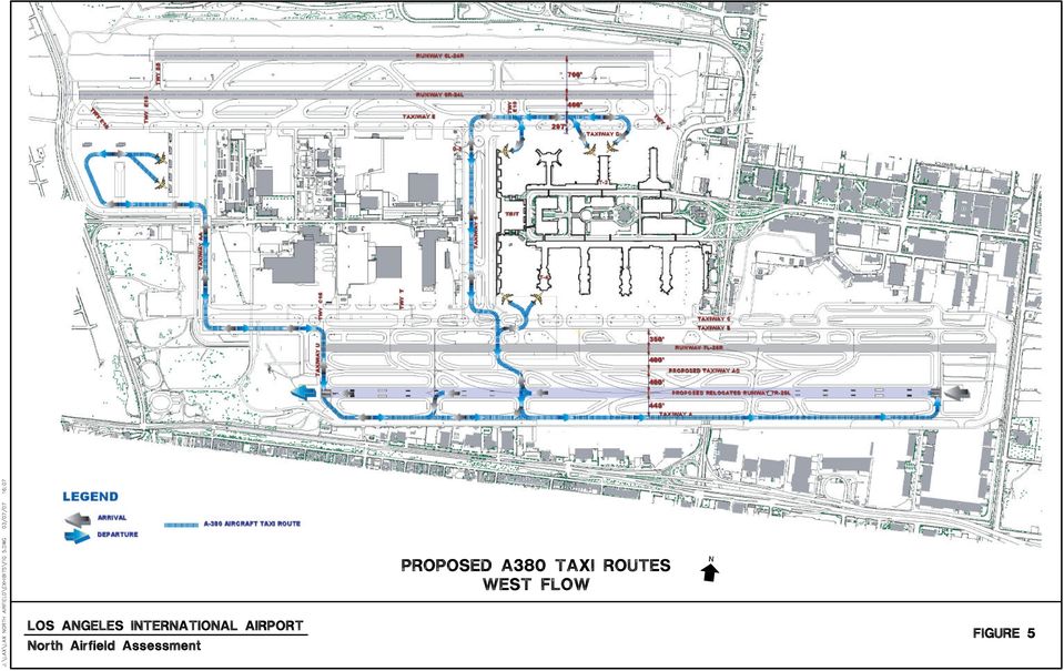
8 Los Angeles International Airport North Airfield Assessment For 2005, a total of 359 of the forecast 1,638 total design day air carrier operations at LAX were performed by large aircraft that generated potential North Airfield conflicts representing just over 22 percent of total air carrier operations. By the year 2008, operations by these larger aircraft would comprise 380 of the 1,637 total design day air carrier aircraft operations or just over 23 percent of the total. By the year 2015, large aircraft operations would total 496 of the forecast 1,621 total design day air carrier aircraft operations, an increase to more than 31 percent of the total forecast design day air carrier operations. Even though the majority of large air carrier aircraft operations presently occur on the South Airfield, the growth of these operations at LAX will result in increasing levels of delay unless an ability to hold these aircraft between the North Airfield s parallel runways is achieved. This is because the outboard runway is closed to additional aircraft landings until the aircraft that penetrates the hold lines is cleared from between the runways. Construction of a center taxiway would eliminate this problem and would greatly assist in FAA operational efforts to reduce runway incursions by providing a taxiing route clear of both runways and their associated clearance requirements. 3.0 THE NEED TO ACCOMMODATE DESIGN GROUP VI AIRCRAFT ON THE NORTH AIRFIELD The introduction of regularly scheduled Design Group VI aircraft operations at LAX should commence sometime within the next 10 to 14 months. Operations by the Airbus A380 were originally scheduled to begin at LAX during However, manufacturing delays have prevented airlines from initiating service. Deliveries of these aircraft to the airlines should begin in the latter half of 2007 with entrance into revenue service shortly thereafter if current schedules are met by Airbus. Based on recent announcements from Airbus, their inaugural flight to LAX is scheduled for later this year. Regarding future Airbus A380 activity, the LAWA has estimated that there will be 17 to 19 daily flights for a total of 34 to 38 daily operations by This estimate is used in this analysis. LAWA previously undertook a study that investigated options to minimize runway incursions on the South Airfield and accommodate Design Group VI aircraft operations. The Southside Airfield and New Large Aircraft (NLA) Study recommended shifting Runway 7L/25R to the south to provide 800 feet of separation from Runway 7R/25L. By providing the 800-foot runway-to-runway centerline separation distance, a parallel center taxiway could be constructed between these two runways. This parallel center taxiway would provide a 400-foot separation from both runways, thereby meeting FAA design criteria for Design Group V aircraft operations. Construction of this center parallel taxiway was ultimately intended to help mitigate the potential for runway incursions on the South Airfield. Runway 7R/25L was originally designated as the South Airfield runway for all Design Group VI aircraft operations, due to the runway s width of 200 feet and available clearances from its parallel taxiways even though it does not meet all Design Group VI standards. Runway 7R/25L is currently the only runway at LAX with a 200-foot width required by FAA design criteria for Design Group VI aircraft operations. The runway s takeoff length of 11,095 feet would also be capable of accommodating virtually all Design Group VI aircraft operations. Taxiway A, which is parallel to and south of Runway 7R/25L, currently has a 500-foot centerline separation distance from Runway 7R/25L. However, the on-going relocation of Runway 7R/25L to the south will result in a slight reduction of the centerline separation distance to approximately 445 feet. This distance is less than the new FAA recommended separation distance of 550 feet on runways with CAT II/III approaches and 500 feet for all other approaches when Design Group VI operations are occurring. Consequently, Design Group VI aircraft will be required to hold 4,000 feet west of the threshold of Runway 25L on Taxiway A during CAT II/III arrivals. Neither the proposed runway to taxiway separation distance between Runway 7R/25L and existing Taxiway A (445 feet) or the future center parallel taxiway (400 feet) will meet FAA design criteria between a runway and a parallel taxiway during operations by Design Group VI aircraft operations. Therefore, both of these parallel taxiways would have to be cleared of aircraft when Design Group VI aircraft operations occur on Runway 7R/25L. The need to clear these taxiways of aircraft when Design Group VI aircraft operations occur will cause significant delays to aircraft operations on the South Airfield unless provisions are made to accommodate Design Group VI aircraft on the North Airfield. Development of the North Airfield with FAA recommended runway-to-taxiway separation distances of 500 feet for all operations other than during CAT II/III conditions and 550 feet during CAT II/III conditions will alleviate the potential for increased airfield delays by providing access to the North and South airfields by Design Group VI aircraft operations. Given the nature of international operations at LAX, wherein most arrivals occur during the mid-morning period and departures occur in the evening, it is likely that there could be a closely timed bank of both arrivals and departures, which could exacerbate airfield delays if Design Group VI aircraft operations are limited to the South Airfield with its taxiway clearance deficiencies and the associated restrictions on aircraft movements. The proposed A380 taxi routes to and from the South Airfield (see Figures 4 and 5) will also impact airline operating costs as all departures to the west will require a significant taxi distance, particularly from the remote gates and the gates at the north end of Tom Bradley International Terminal and Terminal T-2. Development of the North Airfield to accommodate Design Group VI aircraft operations would result in a significant decrease of time and distance required for these aircraft to taxi to and from the runway. 4.0 POTENTIAL NORTH AIRFIELD LAYOUTS The following section provides a brief description of airport design standards and, in particular, the issue of runway centerline to taxiway centerline separation requirements. This information will assist the reader in understanding the rationale for the North Airfield layouts presented in the subsequent section. 4.1 Airport Design Standards This section provides a discussion of current FAA airport design standards and how they compare to the design standards developed in the LAX master plan. Current airport design standards are defined in FAA Advisory Circular 150/ , Airport Design, Change 11, which was published on March 28, By comparison, the LAX master plan references the same FAA Advisory Circular through Change 4, which was published on November 11, Consequently, significant changes occurred to FAA airport design standards during the 13 years between the two publications. One of the most significant changes is the distance required between a runway centerline and a taxiway centerline when accommodating operations by Design Group VI aircraft. At the time of the master plan s preparation, the required distance between a runway centerline and a taxiway separation when accommodating Design Group VI aircraft was 600 feet. The current FAA standard for Design Group VI aircraft is a runway to taxiway separation of 500 feet to accommodate operations during CAT I conditions and 550 feet to accommodate operations during CAT II/III conditions. CAT I 4

9 Los Angeles International Airport North Airfield Assessment conditions include weather minimums down to a 200-foot cloud ceiling height and 0.5 mile horizontal visibility. Category II/III conditions include weather minimums during periods with lower cloud ceilings and lower visibilities. The LAX master plan examined options for providing a runway to taxiway separation less than the 600-foot requirement. The master plan focused on the fact that the required runway-to-taxiway separation distance is based on keeping all parts of an aircraft outside the runway s Obstacle Free Zone (OFZ). The OFZ is a protected volume of airspace that must be kept clear of all obstructions to provide clearance protection for aircraft taking off, landing, or conducting a missed approach. The master plan concluded that a runway to taxiway separation of 520 feet would satisfy the OFZ requirement and proposed its use when planning future runway and taxiway systems at LAX. Recent changes to FAA airport design standards, in particular the requirements associated with conducting missed approaches on runway s accommodating CAT II/III landings, require runway-to-taxiway separations greater than the 520-foot standard proposed by the LAX master plan. A cross section of the 520-foot standard proposed by the LAX master plan is depicted in the upper left corner of Figure 6. The 520-foot clearance would provide proper separation from the runway s CAT II/III OFZ. However, as shown in the upper right corner of Figure 6 the 520 foot separation does not provide sufficient clearance from the missed approach surface associated with CAT II/III operations. This is because a Design Group VI aircraft s tail would penetrate the missed approach surface by more than 3 feet. This missed approach surface has been changed by the FAA since the preparation of the master plan and would present an operational constraint with the proposed 520 foot separation. The operational constraint would consist of the inability to have a Design Group VI aircraft taxi on the parallel taxiway when conducting CAT II/III approaches on the parallel runway. The cross section shown at the bottom of Figure 6 shows that a runway-to-taxiway separation of 550 feet would allow a Design Group VI aircraft to taxi clear of the CAT II/III missed approach surface. This clearance is the basis for the current FAA design standard of a runway to taxiway separation of 550 feet for CAT II/III operations and 500 feet for CAT I operations. These design standards are applied in the proposed North Airfield layouts described in the following section. A benchmarking exercise was conducted to determine how some other major airports in the United States are planning to accommodate operations by Design Group VI aircraft. Many of these airports are site constrained and; therefore, have requested a Modifications of Standards from the FAA. Some of the requested modifications have been approved, while others have been disapproved by the FAA. Appendix A summarizes these Modifications of Standards for the airports contacted. Modification of standards are typically obtained when attempting to accommodate aircraft operations on existing or modified facilities. However, modification of standards are less common when building new facilities. New facilities are expected to meet FAA standards to maximize operational effectiveness. 4.2 North Airfield Alternatives Potential North Airfield layouts were developed to provide proper separation between the inboard and outboard runway, a center taxiway, and proper runway geometrics and runway length to accommodate Design Group VI aircraft operations. Two options were examined for developing airfield layouts. The first option is to maintain the outboard runway in its current location and shift taxiways and the inboard runway south toward existing terminal facilities. This approach requires the reconfiguration of existing terminal concourses and aircraft gates. The second option is to maintain the existing terminal concourses and gates in their current location and shift taxiways and runways to the north. The LAX Master Plan s, Alternative D, proposed the first option. A similar concept was examined in this assessment that maintained the outboard runway in its existing location and shifted all taxiways and the inboard runway south to attain the construction of a center taxiway between the runways and to enable the North Airfield to accommodate Design Group VI aircraft. Figure 7 depicts the required separations to meet current FAA design standards. These separations assume the outboard runway would accommodate Design Group V aircraft, while the inboard runway would accommodate Design Group VI aircraft. The results of this layout indicate that a significant reconfiguration of the existing concourses and aircraft gates at Terminals 1, 2, 3, and at the Tom Bradley International Terminal would be required and; therefore, no significant improvement could be realized over the design proposed by Alternative D. Consequently, layouts were developed for the North Airfield that pursued a second option of maintaining existing terminal courses and gates and shifted existing runways and taxiways to the north. These layouts, which are labeled Alternatives 1 through 5, explore a range of potential runway and taxiway separations that would provide various operational capabilities. Each alternative has been prepared with an A version and a B version. The A version limits each alternative to Pershing Drive to the west and the existing landing threshold of Runway 24R to the east. The A version of the alternatives assumes crossing Pershing Drive is not viable and any extension of the outboard runway is not viable east of the existing Runway 24R landing threshold. The B version of the alternatives assumes Pershing Drive could be crossed with a structure to provide the required RSA beyond the west ends of the runways. The B version also assumes whatever land use and roadway changes are needed at the east end of the runway to accommodate additional runway length could occur. Consequently, runway lengths are constrained with the A version of alternatives and are unconstrained with the B version of alternatives. Appendix B reveals that approximately 11,000 feet of runway is required to accommodate long-haul operations by Design Group VI aircraft without incurring payload penalties. All of the alternatives require changes to surrounding roadway systems and land uses, particularly those in the vicinity of the intersection of South Sepulveda Boulevard and Westchester Parkway. The required changes become more extensive as the separation between the taxiways and runways increase and the outboard runway is shifted farther north. Alternative 1 The purpose of Alternative 1 is to explore the amount of separation needed between the inboard runway and outboard runway to hold Design Group V aircraft between the runways and still comply with FAA clearance requirements during visual and instrument conditions. Alternative 1 would resolve existing operational problems associated with the inability to hold larger aircraft between the runways and would assist the effort to reduce the potential for runway incursions. However, it would not provide the ability to accommodate Design Group VI aircraft on the North Airfield. Alternative 1 would shift the outboard runway 300 feet north of its existing centerline. 5
.")
10 Los Angeles International Airport North Airfield Assessment Alternative 1A Alternative 1A reveals that the existing runways must be separated by 1,000 feet to provide the ability to hold a aircraft short of the inboard runway and attain the required clearances from the outboard runway associated with Category II/III weather conditions. Figure 8 illustrates these clearance requirements with a cross-section drawing. Alternative 1A establishes the west end of the outboard runway so that the required RSA and Runway Object Free Area (ROFA) remain clear of Pershing Drive as depicted in Figure 9. The alternative establishes the east end of the runway perpendicular to the existing landing threshold for Runway 24R. The resulting runway length provides approximately 9,600 feet for takeoffs to the west and approximately 9,700 feet for takeoffs to the east. These runway length are adequate for most aircraft operations, but would not be adequate for long-haul international aircraft operations. The alternative requires the acquisition of property in the vicinity of South Sepulveda Boulevard and Westchester Parkway to provide the required approach lighting system on the east end of the outboard runway. Alternative 1B Alternative 1B provides the same separations as Alternative 1A, but provides a longer runway by assuming that the RSA and ROFA at the west end of the runway could cross over Pershing Drive with the construction of an appropriate bridge structure (see Figure 10). Alternative 1B also assumes that additional runway length could be attained on the east end by extending the runway for takeoffs to the west. Similar to Alternative 1A, this alternative would require the acquisition of additional property to provide the required approach lighting system on the east end of the runway. The resulting runway length with Alternative 1B would be 11,000 feet in each direction. Alternative 2 The purpose of Alternative 2 is to provide proper separation between the inboard and outboard runway that would enable the construction of a center taxiway, provide the ability to hold aircraft between the runways, and accommodate Design Group VI aircraft on the outboard runway. Figure 11 depicts a cross-section drawing of Alternatives 2A and 2B. These alternatives would provide 550 feet of separation between the outboard runway and a center taxiway and an additional 500 feet of separation between the center taxiway and the existing inboard runway. These separations would allow Design Group VI aircraft to operate without restrictions on the outboard runway and comply with all FAA clearance requirements including those associated with CAT II/ III weather conditions. The net effect of this alternative would be that the outboard runway would shift 350 feet north of its existing location. The overall strategy of Alternative 2 is to accommodate Design Group VI aircraft operations exclusively on the outboard runway, thereby eliminating the need to move or change the inboard runway or its parallel taxiways. Alternative 2A Alternative 2A sets the west end of the runway so that the required RSA and ROFA remain clear of Pershing Drive as depicted in Figure 12. The east end of the runway is set abeam the existing landing threshold for Runway 24R. The resulting runway length is approximately 9,600 feet for takeoffs to the west and approximately 9,700 feet for takeoffs to the east. These lengths are not sufficient to accommodate Design Group VI aircraft operations without incurring payload limitations. Alternative 2B Figure 13 depicts Alternative 2B. It provides the 11,000 feet of runway length required for Design Group VI aircraft operations at the same separations proposed by Alternative 2A. This is achieved by proposing that the RSA and ROFA on the west end of the runway cross over Pershing Drive with the construction of an appropriate bridge structure. The alternative also proposes the construction of additional runway east of the existing Runway 24R landing threshold. This additional runway could be used to increase takeoff lengths for departures on the outboard runway. This alternative requires the acquisition of property in the vicinity of South Sepulveda Boulevard and Westchester Parkway to provide the required approach lighting system on the east end of the runway. Alternative 3 Alternative 3 proposes that Design Group VI aircraft operations be accommodated exclusively on the inboard runway and that approaches to both Runway 24L and Runway 24R be Category II/III capable. This would eliminate the need to provide Design Group VI clearances and facilities on the outboard runway, but would require that both runways be shifted to the north. In an effort to further minimize the distance that the North Airfield would have to shift northward, this alternative also proposes that arrivals to Runway 24R be limited to Design Group IV and lower during CAT II/III conditions. During CAT I conditions Design Group V arrivals would be permitted on the outboard runway. This operating configuration would allow the separation between the outboard runway and the center taxiway to be limited to 400 feet. Alternative 3 would shift the outboard runway 390 feet north of its existing centerline. Figure 14 depicts a cross-section drawing of Alternatives 3A and 3B during CAT II/III weather conditions. Sufficient space would be provided to allow a Design Group IV aircraft to hold clear of the CAT II/III OFZ for both the inboard and outboard runway. The figure indicates that a separation of 500 feet would be provided between the center taxiway and the inboard runway and a separation of 550 feet would be provided between the inboard runway and the south parallel taxiway. These respective separations are required to keep Design Group V and VI aircraft clear of the CAT II/III missed approach surface for Runway 24L. In addition to providing the required runway to taxiway separations, Alternative 3 also proposes that the centerline of Taxilane D be shifted 13 feet to the north of its present location to provide the required 138 feet clearance to the aircraft containment line. This would bring the majority of Taxiway D into conformance with the Design Group V standard for a Taxilane Object Free Area (OFA) except for the area near Concourse 1, which extends farther north than Terminals 2 and 3. Alternative 3A Figure 15 depicts Alternative 3A. The west ends of the runways are placed to retain their respective RSAs and OFAs on the east side of Pershing Drive, thereby eliminating the need to bridge the roadway. The east end of the outboard runway is set abeam the existing threshold for the outboard runway. The east end of the inboard runway has two thresholds. The landing threshold is abeam the existing runway threshold. 6
 remain clear of Pershing Drive as depicted in Figure 9.")
11 Los Angeles International Airport North Airfield Assessment However, the departure threshold is shifted eastward to maximize the takeoff distance for departures. The resulting distances for takeoffs on the inboard runway is approximately 10,400 feet. While this distance is adequate for most operations, it is somewhat short of the 11,000 feet previously noted as being required to accommodate long-haul operations. Alternative 3B Figure 16 depicts Alternative 3B. This alternative establishes the east ends of the runways in the same location as proposed by Alternative 3A. However, the west ends of the runways are shifted farther west and require a bridge structure over Pershing Drive to provide the required RSAs. The net effect of this change is to provide a runway length of over 11,300 feet on the inboard runway and nearly 11,000 feet of the outboard runway. These runway lengths would be sufficient to accommodate long-haul operations by Design Groups V and VI aircraft. Alternative 4 Alternative 4 expands on the concept of accommodating Design Group VI aircraft operations on the inboard runway established by Alternative 3, but goes one step further and allows up to Design Group V arrivals on the outboard runway, even during CAT II/III conditions. This is accomplished by increasing the separation between the outboard runway and the center taxiway to 500 feet from the 400 feet proposed by Alternative 3. Figure 17 depicts the resulting cross section of runway and taxiway separations with Alternative 4. Impacts to surrounding roadways and land uses increase with Alternative 4 because of the larger taxiway separation, which results in the outboard runway moving 490 feet north of its existing location. Alternative 4A Figure 18 depicts Alternative 4A. It proposes the same threshold locations and hence the same runway lengths proposed by Alternative 3A. This alternative also corrects the Taxilane D deficiency noted in Alternative 3. However, impacts to surrounding roadway systems and land use become more extensive with Alternative 4A. The ROFA on the north side of the outboard runway encompasses portions of Westchester Parkway. As with Alternative 3A and 3B, this alternative would require that all Design Group VI aircraft operations occur on the inboard runway. Alternative 4B Figure 19 depicts Alternative 4B. This proposes the same threshold locations and hence the same runway lengths proposed by Alternative 3B. Hence, this alternative provides the ability to accommodate long range Design Group VI aircraft operations similar to Alternative 3B. Alternative 5 Alternative 5 is similar to Alternative 4; however, it allows Design Group VI aircraft operations on both the inboard runway and the outboard runway. This would allow the North Airfield to operate in the same manner as it presently does with all takeoffs occurring on the inboard runway and all landings occurring on the outboard runway. This method of operation would simplify air traffic control procedures because aircraft departures on the inboard runway would not need to be metered to allow landings by Design Group VI aircraft. Alternative 5 results in the same total distance (1,550 feet) between the inboard parallel taxiway and the outboard runway centerline as proposed by Alternative 4. However, the larger runway-to-taxiway separation of 550 feet is provided between the center taxiway and the outboard runway instead of between the inboard runway and its south parallel taxiway. This is because the larger separation of 550 feet is only required on the runway where CAT II/III landings are conducted. Alternative 5 would result in the outboard runway s centerline being 490 feet north of the existing outboard runway. Figure 20 provides a crosssection drawing of this alternative and shows the ability to hold a Design Group VI aircraft short of inboard runway while also remaining clear of the CAT II/III OFZ for the outboard runway. Alternative 5A Figure 21 depicts Alternative 5A. This alternative has the same threshold locations on the east and west end of the runway as proposed by Alternative 4A. Thus, it provides the same runway lengths. Runway lengths are limited to approximately 10,400 feet for takeoffs and approximately 9,500 feet for landings. The alternative avoids any impacts to Pershing Drive to the west, but does impact roadway and other land uses to the east. Alternative 5B Figure 22 depicts Alternative 5B. This alternative is essentially the same as Alternative 5A except that it assumes the RSAs on the west will cross over Pershing Drive. This would allow for longer runway lengths and require a bridge structure to be constructed over Pershing Drive. The resulting runways lengths would be approximately 10,200 feet on the outboard runway and approximately 11,000 feet on the inboard runway. This alternative would provide the required runway length for takeoffs of Design Group VI aircraft to longhaul destinations. 4.3 Review of LAX Master Plan Alternative D The LAX master plan s recommended layout for the North Airfield is contained in Alternative D as depicted in Figure 23. That plan used modified Design Group VI standards and significant changes to passenger terminal facilities to provide a center taxiway between the inboard and outboard runways and accommodate Design Group VI aircraft on the North Airfield. The alternative would maintain the existing outboard runway s centerline in its existing location and would rebuild all other North Airfield taxiways and runways by moving them south. The alternative proposes a separation of 520 feet between the outboard runway and the center taxiway and another 520 feet between the center taxiway and the inboard runway. A separation of 400 feet is proposed between the inboard runway and the parallel taxiway to the south (Taxiway E). Finally, a separation of 369 feet is proposed between Taxiway E and the parallel Taxiway D. This concept proposes that all landings, including those by Design Group VI aircraft, occur on the outboard runway and all takeoffs, including those by Design Group VI aircraft, occur on the inboard runway. The alternative also assumes that operational controls are put into effect by air traffic control that would allow Design Group VI aircraft to takeoff on the inboard runway even though the proposed separation of 400 feet to the south parallel taxiway is 100 feet less than the current FAA design standard of 500 feet. The proposed operational control would consist of clearing all aircraft from the parallel taxiway (Taxiway E) when a Design Group VI aircraft takes off from the inboard runway. 7

12 Los Angeles International Airport North Airfield Assessment This concept would achieve the objective of providing a center taxiway between the runways and; therefore, would improve the safety and efficiency of North Airfield operations. It would also enable Design Group VI aircraft operations to use the North Airfield thereby improving efficiency and reducing aircraft delay on the South Airfield. However, Alternative D does not provide the required separation between the inboard runway and the parallel taxiway to the south (Taxiway E). Consequently, all aircraft would have to be cleared from Taxiway E when a Design Group VI aircraft takes off from the inboard runway. This is a significant constraint that would require air traffic control procedures be developed to accommodate this mode of operation. Aircraft delay would increase due to this constraint and would increase in significance with increasing numbers of operations by Design Group VI aircraft on the North Airfield. 5.0 RECOMMENDATION The alternatives presented in the preceding section explore a range of solutions for providing a center taxiway and accommodating Design Group VI aircraft on the North Airfield. Each alternative has advantages and disadvantages in terms of operational, land use, and other factors. Table 3 provides a brief comparison of the alternatives on the basis of some key physical characteristics and operational criteria. TABLE 3 NORTH AIRFIELD ALTERNATIVES COMPARISON Alternative Shifts Outboard Runway Runway Takeoff Length Accommodates Design Group VI Aircraft Rebuilds Option 1 No 10,700 On Inboard Runway 6R/24L 1A 300 North 9,580 No Runway 6L/24R 1B 300 North 11,000 No Runway 6L/24R 2A 350 North 9,621 On Outboard Runway 6L/24R 2B 350 North 11,000 On Outboard Runway 6L/24R 3A 390 North 10,416 On Inboard Both Runways 3B 390 North 11,000 On Inboard Both Runways 4A 490 North 10,416 On Inboard Both Runways 4B 490 North 10,976 On Inboard Both Runways 5A 490 North 10,416 On Both Both Runways 5B 490 North 10,976 On Both Both Runways Source: URS Corporation, As noted at the beginning of Section 4.2, airfield layouts began with an assessment of holding the outboard runway s centerline in its existing location and rebuilding the inboard runway and taxiway to the south (i.e., Option 1). The assessment revealed that Option 1 would not provide the ability to retain more of the concourses or gates in Terminals 1, 2, 3, and the Tom Bradley International Terminal than the proposed LAX master plan Alternative D. Therefore, Option 1 was not examined further and is not recommended. The second option was to examine alternatives that shift the runway system northward from its existing location. These alternatives are labeled 1 through 5 and were developed with A and B versions that varied runway lengths. Alternative 1 would move the outboard runway 300 feet north and would provide the ability to construct a center taxiway between the runways. This would enable aircraft up to and including Design Group V to hold between the runways and remain clear of the OFZs from both runways. This alternative would help address the problem of runway incursions and would improve airfield efficiency, but it would not accommodate Design Group VI aircraft operations. The mode of operation with Alternative 1 (i.e., landings on the outboard runway and takeoffs on the inboard runway) would remain the same as with the existing North Airfield. Alternative 1 is not recommended because it does not provide the ability to accommodate Design Group VI aircraft operations on the North Airfield. This would force all Design Group VI aircraft operations to occur on the South Airfield and would result in significant delays due to the numerous constraints described in Section 3.0. As indicated in the far right column of Table 3, Alternatives 3, 4, and 5 would require rebuilding the entire North Airfield (i.e., both the inboard and outboard runway and all associated taxiways) and consequently would have substantially higher construction costs. Of these alternatives, Alternative 5 would have the highest construction cost due to the need to provide taxiways and runways that meet Design Group VI standards on both the inboard runway and the outboard runway. The ROFAs associated with Alternatives 4 and 5 would encompass portions of Westchester Parkway and; therefore, may require modifications to that roadway in addition to Lincoln Boulevard. Considering the higher cost, impacts and disruption to airfield operations Alternative 3, 4, and 5 are not recommended. Alternative 2 would provide a center taxiway and would accommodate Design Group VI aircraft operations with minimal disruption by allowing Design Group VI aircraft operations to taxi along the center taxiway. A disadvantage of Alternative 2 is that it would change the current mode of operations at the airport by requiring Design Group VI aircraft to takeoff from the outboard runway. However, all other aircraft takeoffs could continue to occur on the inboard runway. Air traffic control would need to coordinate the taxiing of Design Group VI aircraft along the center taxiway so that they do not conflict with arrivals on the outboard runway. The B version of Alternative 2 would provide sufficient runway length (i.e., 11,000 feet) to accommodate long-haul flights by Design Group VI aircraft. The A version of Alternative 2 is limited to a runway length of approximately 9,600 feet. This length would not be sufficient to accommodate long-haul operations and; therefore, is not recommended. Alternative 2B would move the outboard runway 350 feet north of its present location and would require crossing Pershing Boulevard with structure to provide sufficient RSA at the runway s west end. However, the northward shift of this runway would place the portion of the RSA that crosses Pershing Boulevard north of the Blue Butterfly Preserve that exists on the west side of Pershing Drive. Considering the study objectives, operational efficiencies, and cost factors, Alternative 2B offers substantial advantages and is; therefore, recommended. Additional study is required to assess the full range of advantages and disadvantages associated with this alternative including engineering, construction, and environmental impacts. 8
.")
13

14

15

16

17

18

19
20

The total estimated PFC revenue for the application is $266,900,000. The estimated charge effective date for this application is December 1, 2016.
 Public Notice of Application for Authority to Impose and Use Passenger Facility Charges (PFCs) at EWR, LGA, JFK and SWF and Amendment to Approved PFC Applications at EWR, LGA, and JFK The Port Authority
Appendix E FAA ALP Sheet Checklist
 Appendix E FAA ALP Sheet Checklist AC 150/5070-6B (incl. Chg. 1, 5/1/07) Airport Layout Plan Drawing Set The following list provides general guidelines in preparing the Airport Layout Plan set. The individual
MASTER PLAN PREPARATION
 Located in the East Valley of the Phoenix Metropolitan Area, Phoenix-Mesa Gateway Airport is a former military airfield that has successfully made the transition to a full service commercial passenger
AIRCRAFT NOISE ABATEMENT OPERATING PROCEDURES AND RESTRICTIONS
 AIRCRAFT NOISE ABATEMENT OPERATING PROCEDURES AND RESTRICTIONS This section sets forth the Los Angeles World Airports (LAWA s) informal noise abatement traffic; flight and runway use procedures and includes
MASTER PLAN DRAFT RECOMMENDED PLAN
 MASTER PLAN DRAFT RECOMMENDED PLAN City of Atlanta, Department of Aviation September 19, 2014 Draft Recommended Plan This document presents an overview of the findings and recommendations from the Master
INITIAL TEST RESULTS OF PATHPROX A RUNWAY INCURSION ALERTING SYSTEM
 INITIAL TEST RESULTS OF PATHPROX A RUNWAY INCURSION ALERTING SYSTEM Rick Cassell, Carl Evers, Ben Sleep and Jeff Esche Rannoch Corporation, 1800 Diagonal Rd. Suite 430, Alexandria, VA 22314 Abstract This
Current and Forecast Demand
 Existing Facilities A new terminal opened in September 2005 at the Southwest Florida International Airport (RSW), replacing the 17-gate original terminal that opened in 1983. The $438 million Midfield
Radio Communications in Class D Airspace by Russell Still, Master CFI
 Radio Communications in Class D Airspace by Russell Still, Master CFI Class D airspace is one of the most common parts of the airspace system that requires specific radio communications. Although you can
Snohomish County Airport Paine Field
 Snohomish County Airport Paine Field PUGET SOUND REGIONAL COUNCIL AND THE REGIONAL AIRPORT SYSTEM The Puget Sound Regional Council (PSRC) is the planning agency for the central Puget Sound region, which
CHAPTER 3 ALTERNATIVES CONSIDERED
 3.0 INTRODUCTION CHAPTER 3 ALTERNATIVES CONSIDERED The existing Afton Airport parallel taxiway, with its approximate 4,360 foot length, only accommodates one half of the runway s length, and is too short
AIR TRAFFIC INITIAL ENVIRONMENTAL REVIEW
 AIR TRAFFIC INITIAL ENVIRONMENTAL REVIEW Operational Test Period #2 to Evaluate the Feasibility of Changing Runway Configurations at Two Times during the Day at Boston-Logan Airport FAA Order 7400.2 Appendix
10 Aviation Element. 10.1 Introduction. 10.1.1 Purpose of Chapter
 10 Aviation Element 10.1 Introduction 10.1.1 Purpose of Chapter This chapter provides the aviation element of the RFATS 2035 Long Range Transportation Plan. It describes the existing conditions and trends
AGENCY: Federal Aviation Administration (FAA), Department of Transportation.
, Department of Transportation.") This document is scheduled to be published in the Federal Register on 05/11/2016 and available online at http://federalregister.gov/a/2016-11116, and on FDsys.gov [4910-13] DEPARTMENT OF TRANSPORTATION
This document is scheduled to be published in the Federal Register on 05/11/2016 and available online at http://federalregister.gov/a/2016-11116, and on FDsys.gov [4910-13] DEPARTMENT OF TRANSPORTATION
WHICH AIR TRAFFIC CONTROLLER TO CONTACT
 WHICH AIR TRAFFIC CONTROLLER TO CONTACT 1. Introduction This article is written in order to explain to all beginners in the IVAO network the basics for any pilot to contact the correct air traffic controller.
Alternatives RIAC 5.1 INTRODUCTION 5.2 WORKING ASSUMPTIONS
 CHAPTER 5 Runway/Taxiway Alternatives 5.1 INTRODUCTION This chapter presents the development and analysis of different layouts and configurations of both Runway 10-28 and its related taxiways. A primary
CHAPTER 7. AIRSPACE 7.1 AFFECTED ENVIRONMENT
 CHAPTER 7. AIRSPACE 7.1 AFFECTED ENVIRONMENT 7.1.1 Definition of Resource Airspace management is defined as directing, controlling, and handling flight operations in the volume of air that overlies the
Mary C. Frederick, RCE PMP Division Chief. Caltrans Division of Aeronautics 1
 Mary C. Frederick, RCE PMP Division Chief Caltrans Division of Aeronautics 1 Aeronautics Mission Assist in the development and preservation of a safe and environmentally compatible air transportation system
Appendix D GENERAL AVIATION AIRPORTS GROUND VEHICLE OPERATIONS TRAINING PROGRAM
 Appendix D GENERAL AVIATION AIRPORTS GROUND VEHICLE OPERATIONS TRAINING PROGRAM Section 1. Airport Driving Rules and Regulations I. Applicability. This training program applies to all users of, and persons
Airline Fleet Planning Models. 16.75J/1.234J Airline Management Dr. Peter P. Belobaba April 10, 2006
 Airline Fleet Planning Models 16.75J/1.234J Airline Management Dr. Peter P. Belobaba April 10, 2006 Lecture Outline Fleet Planning as part of Strategic Planning Process Airline Evaluation Process Approaches
Airport Safety Management Systems and New Technologies
 Airport Safety Management Systems and New Technologies Presented to: By: Eduardo Angeles, FAA Associate Administrator for Airports Date: Overview Safety Management Systems (SMS) Runway Incursions and Excursion
WATSONVILLE MUNICIPAL AIRPORT MASTER PLAN CITY OF WATSONVILLE, SANTA CRUZ COUNTY, CALIFORNIA CHAPTER 3. AVIATION FORECASTS REVISED APRIL 2010
 WATSONVILLE MUNICIPAL AIRPORT MASTER PLAN CITY OF WATSONVILLE, SANTA CRUZ COUNTY, CALIFORNIA CHAPTER 3. AVIATION FORECASTS REVISED APRIL 2010 TABLE OF CONTENTS WATSONVILLE MUNICIPAL AIRPORT MASTER PLAN
U.S. DEPARTMENT OF TRANSPORTATION FEDERAL AVIATION ADMINISTRATION. National Policy. SUBJ: OpSpec A021, Helicopter Air Ambulance (HAA) Operations
 Operations") NOTICE U.S. DEPARTMENT OF TRANSPORTATION FEDERAL AVIATION ADMINISTRATION National Policy N 8900.A021 Effective Date: XX/XX/XX Cancellation Date: XX/XX/XX SUBJ: OpSpec A021, Helicopter Air Ambulance (HAA)
NOTICE U.S. DEPARTMENT OF TRANSPORTATION FEDERAL AVIATION ADMINISTRATION National Policy N 8900.A021 Effective Date: XX/XX/XX Cancellation Date: XX/XX/XX SUBJ: OpSpec A021, Helicopter Air Ambulance (HAA)
4 EXISTING AND FORECAST NOISE EXPOSURE MAPS
 Updated 14 C.F.R. Part 150 Noise Exposure Maps page 53 4 EXISTING AND FORECAST NOISE EXPOSURE MAPS 4.1 Introduction As discussed in Section 1.3.1, the most fundamental elements of the NEMs submission are
Cessna 172SP & NAV III Maneuvers Checklist
 Cessna 172SP & NAV III Maneuvers Checklist Introduction Power Settings This document is intended to introduce to you the standard method of performing maneuvers in Sunair Aviation s Cessna 172SP and NAV
Airport Master Plan Demand/Capacity Analysis and Facility Requirements Summary
 Hartsfield-Jackson Atlanta International Airport Airport Demand/Capacity Analysis and Facility Requirements Summary PREPARED FOR: City of Atlanta, Department of Aviation PREPARED BY: RICONDO & ASSOCIATES,
IFR Operators Briefing Pack. May 2013
 IFR Operators Briefing Pack May 2013 Uncontrolled If Printed. Not Valid After 30/12/2012 Contents Introduction 4 Runways And Operation Modes 4 ATC Control Procedures 5 Arriving IFR Aircraft 5 Speed Control
Departures to the south from Runways 16L and 16R.
 Mode 5 Method of operation Departures to the south from Runways 16L and 16R. Arrivals from the east on Runway 25. Arrivals from the north for those aircraft requiring to use the long runway. This runway
(3) CATEGORY III means a permanent heliport facility. (4) COMMISSION means the City of Austin Airport Advisory Commission.
 CATEGORY III means a permanent heliport facility. (4) COMMISSION means the City of Austin Airport Advisory Commission.") 13-1-171 DEFINITIONS. (A) Terms not otherwise defined in this article have the meaning prescribed by applicable aviation law, including Federal Aviation Administration Advisory Circular 150/5390-2A (Heliport
13-1-171 DEFINITIONS. (A) Terms not otherwise defined in this article have the meaning prescribed by applicable aviation law, including Federal Aviation Administration Advisory Circular 150/5390-2A (Heliport
AVIATION INVESTIGATION REPORT A06F0014 MISALIGNED TAKE-OFF
 AVIATION INVESTIGATION REPORT A06F0014 MISALIGNED TAKE-OFF AIR CANADA AIRBUS A319-114 C-FYKR LAS VEGAS, NEVADA 30 JANUARY 2006 The Transportation Safety Board of Canada (TSB) investigated this occurrence
2006 Report Card for Pennsylvania s Infrastructure
 AVIATION C- 2006 Report Card for Pennsylvania s Infrastructure Philadelphia International Airport (PHL) is currently one of the fastest growing airports in the world. It is also one of the most delay-prone
LONG-TERM INFRASTRUCTURE DEVELOPMENT PLAN
 Louis Armstrong New Orleans International Airport LONG-TERM INFRASTRUCTURE DEVELOPMENT PLAN April 2013 TABLE OF CONTENTS 03. INTRODUCTION 04. PURPOSE AND NEED 06. ALTERNATIVES ANALYSIS 10. KEY ELEMENTS
Analytics That Allow You To See Beyond The Cloud. By Alex Huang, Ph.D., Head of Aviation Analytics Services, The Weather Company, an IBM Business
 Analytics That Allow You To See Beyond The Cloud By Alex Huang, Ph.D., Head of Aviation Analytics Services, The Weather Company, an IBM Business Table of Contents 3 Ways Predictive Airport Analytics Could
Airport Safety and Construction Management Under The FAA
 U.S. Department of Transportation Federal Aviation Administration Advisory Circular Subject: Quality Management for Federally Funded Airport Construction Projects Date: DRAFT Initiated by: AAS-100 AC No.:
12.0 SAFETY AND SECURITY
 12.0 SAFETY AND SECURITY 12.0 SAFETY AND SECURITY Key points The development plan within this Master Plan: Will improve airfield safety by reducing the towed aircraft runway crossings and other airfield
and Implementing Rules for Air Operations of Community Operators F. Cross Reference Tables
 European Aviation Safety Agency 30 Jan 2009 NOTICE OF PROPOSED AMENDMENT (NPA) NO 2009 02F DRAFT OPINIONS OF THE EUROPEAN AVIATION SAFETY AGENCY, FOR A COMMISSION REGULATION establishing the implementing
Mercer County Multi-Modal Transportation Plan Year 2025 Travel Demand Model
 Mercer County Multi-Modal Transportation Plan Year 2025 Travel Demand Model Prepared For West Virginia Department of Transportation Transportation Planning Division Building 5, Room 824 1900 Kanawha Blvd.
Air Medical Transport Planning Good planning can save lives. Planning for air medical transport
 Chapter 1 2 15 Air Medical Transport Planning Good planning can save lives. Planning for air medical transport is important to maximize efficiency and safety; it helps create the best care for patients.
The Port of Oakland executed various settlement
 Executive Summary 1 The executive summary provides a brief summary of the master plan for Oakland International Airport (OAK). It has the following sections: Background and Overview Background The Port
Aviation Demand Forecasting
 Airports Commission Discussion Paper 01 Aviation Demand Forecasting The Mayor of London s response March 2013 1. Purpose of paper 1.1. In February 2013, the Airports Commission issued a Discussion Paper
How To Know The History Of The Airport
 Pekin Municipal Airport (C1) John C. Kriegsman Air Field: Fact Sheet General aviation airport included in the National Plan of Integrated Airport Systems (NPIAS) Federally funded at an estimated $6,81,412
3.0 FACILITY REQUIREMENTS
 3.0 FACILITY REQUIREMENTS This chapter identifies the facility requirements necessary to meet existing and forecast airport requirements, satisfy FAA design standards, and improve safety. The facility
Presentation to Morse Study Area Taskforce. Executive Airport Area Compatibility Plan and One-Mile Zoning Reviews March 1, 2011
 Presentation to Morse Study Area Taskforce Executive Airport Area Compatibility Plan and One-Mile Zoning Reviews March 1, 2011 151st Street and Pflumm Road: In the cities of Olathe and Overland Park. Its
The Basis for Our Decision
 October 31, 2014 Exemption No. 10009C Regulatory Docket No. FAA-2009-0702 Mr. Stephen Craven Angel Flight Mid-Atlantic Airlift Hope of America Mercy Medical Airlift 4620 Haygood Road, Suite 1 Virginia
Date: 10/10/2014 Initiated by: AAS-100
 U.S. Department of Transportation Federal Aviation Administration Advisory Circular Subject: Airport Pavement Management Program (PMP) Date: 10/10/2014 Initiated by: AAS-100 AC No: 150/5380-7B Change:
Training program for S2 (TWR) rating
 rating") Training program for S2 (TWR) rating Introduction This is the official Vatsim Scandinavia training program for students training for the TWR (S2) Rating. Each mentor is expected to take his student through
Training program for S2 (TWR) rating Introduction This is the official Vatsim Scandinavia training program for students training for the TWR (S2) Rating. Each mentor is expected to take his student through
The Need for Traffic Incident Management
 The Need for Traffic Incident Management With traffic incidents responsible for approximately 50-60% of the congestion delays motorists encounter on the nation s roadways every day, increased roadway capacity
Airspace. Chapter 14. Introduction
 Chapter 14 Airspace Introduction The two categories of airspace are: regulatory and nonregulatory. Within these two categories there are four types: controlled, uncontrolled, special use, and other airspace.
Existing Facilities. Current and Forecast Demand
 Existing Facilities JIA is served by a number of airside and landside facilities. There are two runways that serve the airport in an open V configuration. The Annual Service Volume (ASV) of the runway
STRESS FRACTURE ON A BOEING 757 : OBSERVATIONS BY A GEOLOGIST May 21, 2012
 STRESS FRACTURE ON A BOEING 757 : OBSERVATIONS BY A GEOLOGIST Richard R. Donofrio May 21, 2012 Oklahoma City, OK As geologists we are accustomed to observing rock fractures in outcrops, cores, and elsewhere,
Environmental Impact Statement for Las Vegas Supplemental Commercial Service Airport. Peter Byrne, Deputy Project Manager
 Environmental Impact Statement for Las Vegas Supplemental Commercial Service Airport Peter Byrne, Deputy Project Manager Supplemental Commercial Service Airport Roles and Responsibilities in the EIS Process
COMMERCIAL AND GENERAL AVIATION
 Existing Facilities Daytona Beach International Airport is served by a number of airside and landside facilities. The airport has three asphalt runways: Runway 7L/25R (10,500 feet long by 150 feet wide),
INTERNATIONAL CIVIL AVIATION ORGANIZATION
 INTERNATIONAL CIVIL AVIATION ORGANIZATION AOP/WG/3 WP/18 THE THIRD MEETING OF THE AERODROMES OPERATIONS AND PLANNING WORKING GROUP (AOP/WG/3) Putrajaya, Malaysia, 2 4 June 2015 Agenda Item 4: Provision
NATIONAL TRANSPORTATION SAFETY EOARD WASH IN GTO N, D. C.
 NATIONAL TRANSPORTATION SAFETY EOARD WASH IN GTO N, D. C. ISSUED: November 17. 1978 Honorable Langhorne M. Bond Admini strator Federal Aviation Administration Washington, D. C. 20591 -----------------_--
Airline Schedule Development
 Airline Schedule Development 16.75J/1.234J Airline Management Dr. Peter Belobaba February 22, 2006 Airline Schedule Development 1. Schedule Development Process Airline supply terminology Sequential approach
VDFP General Aviation Firefighting for Structural Firefighters
 VIRGINIA DEPARTMENT OF FIRE PROGRAMS Aviation Firefighting for Chapter 3 Communications 3-1 Learning Objectives Understand the correct radio procedures for talking to pilots or airport personnel List examples
 Federal Aviation Administration Report on NextGen Performance Metrics Pursuant to FAA Modernization and Reform Act of 2012, H.R. 658, Section 214 2013 Introduction The Next Generation Air Transportation
ADS-B is intended to transform air traffic control by providing more accurate and reliable tracking of airplanes in flight and on the ground.
 ADS-B is intended to transform air traffic control by providing more accurate and reliable tracking of airplanes in flight and on the ground. New Air Traffic Surveillance Technology Air traffic service
AN AIRCRAFT TAXI SIMULATION MODEL FOR THE UNITED PARCEL SERVICE LOUISVILLE AIR PARK. W. Swain Ottman Angela C. Ford Gregory R.
 Proceedings of the 1999 Winter Simulation Conference P. A. Farrington, H. B. Nembhard, D. T. Sturrock, and G. W. Evans, eds. AN AIRCRAFT TAXI SIMULATION MODEL FOR THE UNITED PARCEL SERVICE LOUISVILLE AIR
Table of Contents 1. INTRODUCTION 2 2. DEFINITION 4 3. UAS CLASSIFICATION 6 4. REGULATORY PRINCIPLES 16 5. INTERACTION WITH AIR TRAFFIC CONTROL 16
 FOREWORD Table of Contents 1. INTRODUCTION 2 2. DEFINITION 4 3. UAS CLASSIFICATION 6 4. REGULATORY PRINCIPLES 16 5. INTERACTION WITH AIR TRAFFIC CONTROL 16 6. SENSE AND AVOID ( required for applicants
Background on Airspace
 Background on Airspace There are six classifications of airspace in the United States; A, B, C, D, E, and G. Class A is the most restrictive and Class G the least restrictive. They can be categorized as:
4.27 Schools (CEQA) 4.27.1 Introduction. 4.27.2 General Approach and Methodology
 4.27.1 Introduction. 4.27.2 General Approach and Methodology") 4.27.1 Introduction The schools analysis addresses the project-generated changes in public school enrollment in the Los Angeles Unified School District (LAUSD) and the extent to which such changes could
4.27.1 Introduction The schools analysis addresses the project-generated changes in public school enrollment in the Los Angeles Unified School District (LAUSD) and the extent to which such changes could
3.1 Introduction. Ronald Reagan Washington National Airport
 III. 3.1 Introduction FAA Order 1050.1E 1 and FAA Order 5050.4B 2 establish the FAA s policies and procedures for compliance with NEPA and the implementing regulations issued by the CEQ (40 CFR Parts 1500-1508).
COMMERCIAL AND GENERAL AVIATION
 Existing Facilities Melbourne International Airport is served by three runways and a number of airside and landside facilities. The runways include Runway 05/23 (3,001 feet long by 75 feet wide), Runway
Document Name: Driving Skills. Purpose: To outline necessary driving skills required to maximize driving safety.
 Document Name: Driving Skills Date Created: 8 October 2013 Date Reviewed: 4 February 2014 Date Approved: 29 July 2015 Purpose: To outline necessary driving skills required to maximize driving safety. Overview:
ADA POST INSPECTION CHECKLIST. Job No. Route County Location
 ADA POST INSPECTION CHECKLIST Job No. Route County Location SIDEWALKS All sidewalks constructed within the project limits are ADA compliant. Sidewalks are 5 or greater in width. Exception, existing sidewalks
VATSIM CODE OF CONDUCT
 VATSIM CODE OF CONDUCT VATSIM is an online community created for enthusiasts of flight simulation and air traffic control. One of the main goals of VATSIM is to create an environment which is fun and,
Welcome! To the. Public Open House
 Welcome To the Public Open House What is an Environmental Assessment? An Environmental Assessment (EA) is a concise document used to describe a proposed action s anticipated environmental impacts. The
3.1 Historical Considerations
 3. Recommended Scope of Bridge improvements 3.1 Historical Considerations In the fall of 2000, an outside consultant, Fraser Design, suggested that the existing 4 th St. Bridge is potentially eligible
Table of Contents for Model Airport Affected Area Regulations
 Table of Contents for Model Airport Affected Area Regulations Section I. General Provisions A. Title...1 B. Authority...1 C. Purpose and Intent...1 D. Designation of Airport Affected Area...1 E. Jurisdiction...2
100% SucceSSfull at Stopping overruns
 100% SucceSSfull at Stopping overruns CouRTeSY of YeAGer AIRpoRT Yeager Airport, Charleston, WV, January 19, 2010 CRJ 200 safely arrested, saving 34 lives ESCO AEROSAFETY & TECHNOLOGY Emergency Arresting
> Current Operations & Business Context. Bankstown Airport Master Plan 2004/05. Bankstown Airport / Master Plan > 29
 Bankstown Airport Master Plan 2004/05 Bankstown Airport / Master Plan > 29 8.1 Bankstown Airport s Role in the Sydney Basin Bankstown Airport is the premier GA airport in NSW. In addition to servicing
Current Market. Predicting the future is a risky business. Meet your new
 By Dawsalee Griffin Meet your new Current Market Outlook What s in store for the next 20 years of the global jetliner market? The just-released version of this annual Boeing report offers the company s
H is for HELP! He was employed as an EMS pilot in Buffalo New York for about 2 years, than transferred to work as a relief pilot through out WI.
 H is for HELP! Wind Turbines and EMS helicopters in Wisconsin This interview with retired EMS pilot Ray Slavik, was submitted to the Calumet County Ad Hoc Committee researching proposed ordinances governing
9988 REDWOOD AVENUE PROJECT TRAFFIC IMPACT ANALYSIS. April 24, 2015
 9988 REDWOOD AVENUE PROJECT TRAFFIC IMPACT ANALYSIS April 24, 2015 Kunzman Associates, Inc. 9988 REDWOOD AVENUE PROJECT TRAFFIC IMPACT ANALYSIS April 24, 2015 Prepared by: Bryan Crawford Carl Ballard,
Springdale Fire Department Policy & Procedures Manual Volume 2 Operations Section 203 Fire Operations 203.20 City Airport Emergency Plan
 Springdale Fire Department Policy & Procedures Manual Volume 2 Operations Section 203 Fire Operations 203.20 City Airport Emergency Plan In order to better protect the lives and property on and around
Data Review and Analysis Program (DRAP) Flight Data Visualization Program for Enhancement of FOQA
 Flight Data Visualization Program for Enhancement of FOQA") 86 Data Review and Analysis Program (DRAP) Flight Data Visualization Program for Enhancement of FOQA Koji MURAOKA and Noriaki OKADA, Flight Systems Research Center, E-mail: muraoka@nal.go.jp Keywords:
86 Data Review and Analysis Program (DRAP) Flight Data Visualization Program for Enhancement of FOQA Koji MURAOKA and Noriaki OKADA, Flight Systems Research Center, E-mail: muraoka@nal.go.jp Keywords:
Capacity Analysis and Facility Requirements
 Capacity Analysis and Facility Requirements Introduction The capacity analysis for is composed of two distinct elements: the ability of airport facilities to accommodate existing and projected aircraft
CHICO MUNICIPAL AIRPORT MOVEMENT AREA DRIVER TRAINING PROGRAM
 CHICO MUNICIPAL AIRPORT MOVEMENT AREA DRIVER TRAINING PROGRAM Introduction In compliance with Federal Aviation Regulations (FAR) Part 139.329, and to provide for a safe operating environment for tenants,
OPERATING MINIMA FOR AEROPLANES AND HELICOPTER OPERATIONS PURPOSE REFERENCE 4.0 DEFINITION
 ORDER TCAA-O-OPS034A March 2013 OPERATING MINIMA FOR AEROPLANES AND HELICOPTER OPERATIONS PURPOSE 1. This Order gives guidance to the Authority s Operations Inspector on the procedures for approval of
The Mayor of London s Submission:
 Inner Thames Estuary Feasibility Study Response to Airports Commission Call for Evidence The Mayor of London s Submission: Supporting technical documents 23 May 2014 Title: Runway utilisation Author: Atkins
International Civil Aviation Organization WORLDWIDE AIR TRANSPORT CONFERENCE (ATCONF) SIXTH MEETING. Montréal, 18 to 22 March 2013
 SIXTH MEETING. Montréal, 18 to 22 March 2013") International Civil Aviation Organization ATConf/6-WP/11 10/12/12 WORKING PAPER WORLDWIDE AIR TRANSPORT CONFERENCE (ATCONF) SIXTH MEETING Montréal, 18 to 22 March 2013 Agenda Item 2: Examination of key
International Civil Aviation Organization ATConf/6-WP/11 10/12/12 WORKING PAPER WORLDWIDE AIR TRANSPORT CONFERENCE (ATCONF) SIXTH MEETING Montréal, 18 to 22 March 2013 Agenda Item 2: Examination of key
2014 NIFA CRM Contestant Briefing Guide San Diego, California
 2014 NIFA CRM Contestant Briefing Guide San Diego, California Region 2 SAFECON 2014 November 12 15 This document supports the 2014 NIFA Collegiate Cockpit Resource Management Simulation and is not for
CRQ MASTER PLAN Public Workshop #2 CRQ MASTER PLAN Public Workshop #2
 CRQ MASTER PLAN May 7, 2014 Overview/Agenda Welcome & Introductions Where we are Facility Requirements Optimum Targets Remaining within existing property limits Format of Workshop Station 1: Master Plan
Chicago Center Fire Contingency Planning and Security Review
 Chicago Center Fire Contingency Planning and Security Review Background In the early morning hours of September 26, 2014, the Federal Aviation Administration s (FAA) Chicago Air Route Traffic Control Center
Policy Regarding Datalink Communications Recording Requirements. AGENCY: Federal Aviation Administration (FAA), Department of Transportation (DOT).
, Department of Transportation (DOT).") [4910-13] DEPARTMENT OF TRANSPORTATION Federal Aviation Administration 14 CFR Parts 91, 121, 125, and 135 [Docket No. FAA 2015-0289] Policy Regarding Datalink Communications Recording Requirements AGENCY:
[4910-13] DEPARTMENT OF TRANSPORTATION Federal Aviation Administration 14 CFR Parts 91, 121, 125, and 135 [Docket No. FAA 2015-0289] Policy Regarding Datalink Communications Recording Requirements AGENCY:
Cuyahoga County Airport - A Guide to Funding Capital Improvements
 7.01 General CHAPTER 7 - FINANCIAL PLAN This chapter presents a financial plan to assist with future capital improvements and provide a guide for implementing the development of Cuyahoga County Airport.
CHAPTER 2 TRAFFIC SIGNS AND HIGHWAY MARKINGS
 CHAPTER 2 TRAFFIC SIGNS AND HIGHWAY MARKINGS This chapter summarizes traffic signs, signals and road markings that control the flow of traffic, making streets and highways safer for motorists, bicyclists
We look forward to the meeting, which will also address the next steps in the study process.
 Airport & Aviation Consultants November 26, 2013 Mr. Randall Malik Ms. Michelle Hannah Executive Director Project Manager Cuero Development Corporation TxDOT Aviation Division 212 East Main Street 125
Sixteenth Meeting of the Cross Polar Trans East Air Traffic Management Providers Work Group (CPWG/16) (Ottawa, Canada 3-6 December 2013)
 (Ottawa, Canada 3-6 December 2013)") CPWG/16 IP/19 03/12/13 Sixteenth Meeting of the Cross Polar Trans East Air Traffic Management Providers Work Group (CPWG/16) Agenda Item 5: Status on CPWG/15 Actions (Ottawa, Canada 3-6 December 2013)
CPWG/16 IP/19 03/12/13 Sixteenth Meeting of the Cross Polar Trans East Air Traffic Management Providers Work Group (CPWG/16) Agenda Item 5: Status on CPWG/15 Actions (Ottawa, Canada 3-6 December 2013)
AVIATION INVESTIGATION REPORT A02P0004 OPERATING IRREGULARITY
 AVIATION INVESTIGATION REPORT A02P0004 OPERATING IRREGULARITY NAV CANADA COMMUNICATIONS EQUIPMENT FAILURE VANCOUVER AREA CONTROL CENTRE 04 JANUARY 2002 The Transportation Safety Board of Canada (TSB) investigated
ICAO Standard Phraseology A Quick Reference Guide for Commercial Air Transport Pilots
 ICAO Standard Phraseology A Quick Reference Guide for Commercial Air Transport Pilots Communication error is the biggest causal factor in both level busts and runway incursions in Europe. This document
14.0 AVIATION. I. Introduction 6/142010
 14.0 AVIATION I. Introduction Aviation plays an important role in the MARC region. As a mode of transportation, aviation provides vital connections for people and goods to destinations inside and outside
CCTV PIPE INSPECTION AND EVALUATION RUNWAY 17L-35R
 CCTV PIPE INSPECTION AND EVALUATION For RUNWAY 17L-35R At ST. PETERSBURG CLEARWATER INTERNATIONAL AIRPORT February 2011 CCTV PIPE INSPECTION AND EVALUATION RUNWAY 17L-35R ST. PETERSBURG CLEARWATER INTERNATIONAL
Hospital Heliport Inspection Basics
 Hospital Heliport Inspection Basics Eric Peltier Aviation Representative Office of Aeronautics 222 E Plato Blvd St. Paul, MN 55107 651 234 7184 eric.peltier@state.mn.us Sources FAA AC 150/5390 2C Heliport
A380 Commercial Update for JP Morgan
 Jean-Pierre Dambrine A380 Marketing Director Commercial Update for JP Morgan 9 th Own the Sky All around the world All around the world The most efficient way to grow Network optimiser, yield booster The
Tauranga, Bay of Plenty
 19/12 720 NZZC Tauranga Aerodrome Airshow and Restricted Area NZR286 Effective: 28 to 29 JAN 12 PORTAVEX 2012 and CLAIC OF THE KY will be held at Tauranga AD during the period 27 to 29 JAN 12. This event
3 Tappan Zee Bridge Rehabilitation Options
 3 Tappan Zee Bridge Rehabilitation Options 3.1 Introduction This chapter describes possible options that rehabilitate and enhance the existing Tappan Zee Bridge. Four Rehabilitation Options have been developed:
Federal Aviation Administration
 Before the Subcommittee on Aviation, Committee on Transportation and Infrastructure U.S. House of Representatives For Release on Delivery Expected at 1:30 p.m. EST Wednesday March 14, 2001 Report Number:
Plan of Construction Operations (PCO)
") REQUEST FOR PROPOSAL APPENDIX G Plan of Construction Operations 13 006 A Taxi A Expansionn CLIENT: TradePort International Corporation, Operators of John C. Munro Hamilton International Airport (YHM) April
REQUEST FOR PROPOSAL APPENDIX G Plan of Construction Operations 13 006 A Taxi A Expansionn CLIENT: TradePort International Corporation, Operators of John C. Munro Hamilton International Airport (YHM) April
WATER SUPPLY SYSTEMS FOR 150/5220-4B AAS-100 AIRCRAFT FIRE AND RESCUE PROTECTION
 WATER SUPPLY SYSTEMS FOR 150/5220-4B AAS-100 AIRCRAFT FIRE AND RESCUE PROTECTION 1. PURPOSE. This Advisory Circular (AC) provides guidance for the selection of a water source and standards for the design