Prestige 2602R-D1A. Support Notes. Version 3.40 Sep. 2007
|
|
|
- Myron Doyle
- 8 years ago
- Views:
Transcription
1 Prestige 2602R-D1A Support Notes Version 3.40 Sep. 2007
2 INDEX APPLICATION NOTES... 5 GENERAL APPLICATION NOTES... 5 INTERNET CONNECTION... 5 Setup the Prestige as a DHCP Relay Configure an Internal Server Behind SUA Configure a PPTP server Behind SUA Using NAT / Multi-NAT About Filter & Filter Examples Using the Dynamic DNS (DDNS) Network Management Using SNMP Using syslog Using IP Alias Using Call Scheduling Using IP Multicast Using Prestige traffic redirect Using Universal Plug n Play (UPnP) VOIP APPLICATION NOTES Setup SIP Account Peer to Peer call Phone port settings Advanced voice settings configuration Phone book Speed dial Voice Common Settings Voice - QoS setup Call Forwarding setup Call Hold setup Call Waiting setup Three Way Conference setup Call Transfer setup Internal Call Call Fallback Call Park / Call Pickup Call Return Distinctive Ringing Do Not Disturb (DND)
3 Hot Line (Auto Dial) Music on hold MWI Caller ID enable/disable Early Media Country Code FAQ ZYNOS FAQ What is ZyNOS? How do I access the embedded web configurator? What is the default LAN IP address and Password? Moreover, how do I change it? How do I upload the ZyNOS firmware code via embeded web configurator? How do I upgrade/backup the ZyNOS firmware by using FTP client program via LAN? How do I upload or backup ROMFILE via web configurator? How do I backup/restore configurations by using FTP client program via LAN? Why can't I make Telnet to Prestige from WAN? What should I do if I forget the system password? What is SUA? When should I use SUA? What is the difference between NAT and SUA? How many network users can the SUA/NAT support? What are Device filters and Protocol filters? Why can't I configure device filters or protocol filters? PRODUCT FAQ What is the Prestige Integrated Access Device? Will the Prestige work with my Internet connection? What do I need to use the Prestige? What is PPPoE? Does the Prestige support PPPoE? How do I know I am using PPPoE? Why does my provider use PPPoE? Which Internet Applications can I use with the Prestige? How can I configure the Prestige? What network interface does the Prestige support? What can we do with Prestige? Does Prestige support dynamic IP addressing? What is the difference between the internal IP and the real IP from my ISP?
4 How does work through the Prestige? Is it possible to access a server running behind SUA from the outside Internet? If possible, how? What DHCP capability does the Prestige support? How do I used the reset button, more over what field of parameter will be reset by reset button? What network interface does the new Prestige series support? How does the Prestige support TFTP? Can the Prestige support TFTP over WAN? How fast can the data go? What is Multi-NAT? When do I need Multi-NAT? What IP/Port mapping does Multi-NAT support? What is the difference between SUA and Multi-NAT? What is BOOTP/DHCP? What is DDNS? When do I need DDNS service? What DDNS servers does the Prestige support? What is DDNS wildcard? Does the Prestige support DDNS wildcard? Can the Prestige SUA handle IPsec packets sent by the VPN gateway behind Prestige? How do I setup my Prestige for routing IPsec packets over SUA? VOIP FAQ What is Voice over IP? How does Voice over IP work? Why use VoIP? What is the relationship between codec and VoIP? What advantage does Voice over IP can provide? What is the difference between H.323 and SIP? Can H.323 and SIP interoperate with one another? What is voice quality? How are voice quality normally rated? What is codec? What is the relation of codec and VoIP? What codec does Prestige support? Which codec should I choose? What do I need in order to use SIP? Unable to register with the SIP server? I can register but can not establish a call?
5 I can make a call but the voice only goes one way not bothway? I can receive a call but the voice only goes one way not bothway? If all the about have been tried, but register still fail what should I do? I suspect there is a hardware problem with my Prestige what should I do? FIREWALL FAQ What is a network firewall? What makes Prestige firewall secure? What are the basic types of firewalls? What kind of firewall is the Prestige? Why do you need a firewall when your router has packet filtering and NAT built-in? What is Denials of Service (DoS)attack? What is Ping of Death attack? What is Teardrop attack? What is SYN Flood attack? What is LAND attack? What is Brute-force attack? What is IP Spoofing attack? What are the default ACL firewall rules in Prestige? How can I protect against IP spoofing attacks? CONTENT FILTER FAQ TROUBLE SHOOTING USING EMBEDDED PACKET TRACE DEBUG PPPOE CONNECTION CLI COMMAND LIST Application Notes General Application Notes Internet Connection A typical Internet access application of the Prestige is shown below. For a small office, there are some components needs to be checked before accessing the Internet. 5
6 Before you begin Setting up the Windows Setting up the Prestige router Troubleshooting Before you begin The Prestige is shipped with the following factory default: 1. IP address = , subnet mask = (24 bits) 2. DHCP server enabled with IP pool starting from Default SMT menu password = 1234 Setting up the PC (Windows OS) 1. Ethernet connection All PCs must have an Ethernet adapter card installed. If you only have one PC, connect the PC's Ethernet adapter to the Prestige's LAN port with a crossover (red one) Ethernet cable. If you have more than one PC, both the PC's Ethernet adapters and the Prestige's LAN port must be connected to an external hub with straight Ethernet cable. 2. TCP/IP Installation 6
7 You must first install TCP/IP software on each PC before you can use it for Internet access. If you have already installed TCP/IP, go to the next section to configure it; otherwise, follow these steps to install: In the Control Panel/Network window, click Add button. In the Select Network Component Type windows, select Protocol and click Add. In the Select Network Protocol windows, select Microsoft from the manufacturers, then select TCP/IP from the Network Protocols and click OK. 3. TCP/IP Configuration Follow these steps to configure Windows TCP/IP: In the Control Panel/Network window, click the TCP/IP entry to select it and click Properties button. In the TCP/IP Properties window, select obtain an IP address automatically. Note: Do not assign arbitrary IP address and subnet mask to your PCs, otherwise, you will not be able to access the Internet. Click the WINS configuration tab and select Disable WINS Resolution. Click the Gateway tab. Highlight any installed gateways and click the Remove button until there are none listed. Click the DNS Configuration tab and select Disable DNS. Click OK to save and close the TCP/IP properties window Click OK to close the Network window. You will be prompted to insert your Windows CD or disk. When the drivers are updated, you will be asked if you want to restart the PC. Make sure your Prestige is powered on before answering Yes to the prompt. Repeat the above steps for each Windows PC on your network. Setting up the Prestige router The following procedure is for the most typical usage of the Prestige where you have a single-user account (SUA). The Prestige supports embedded web server that allows you to use Web browser to configure it. Before configuring the router using Browser please be sure there is no Telnet or Console login. 1. Retrieve Prestige Web 7
8 Please enter the LAN IP address of the Prestige router in the URL location to retrieve the web screen from the Prestige. The default LAN IP of the Prestige is See the example below. Note that you can either use 2. Login first The default password is the default SMT password, '1234'. 3. Configure Prestige for Internet access by using WIZARD SETUP 8
9 The Web screen shown below takes PPPoE as the example. 9
10 Setup the Prestige as a DHCP Relay What is DHCP Relay? DHCP stands for Dynamic Host Configuration Protocol. In addition to the DHCP server feature, the P2602 supports the DHCP relay function. When it is configured as DHCP server, it assigns the IP addresses to the 10
11 LAN clients. When it is configured as DHCP relay, it is reponsable for forwarding the requests and responses negotiating between the DHCP clients and the server. See figure 1. Setup the Prestige as a DHCP Client 1. Toggle the DHCP to Relay in menu 3.2 and enter the IP address of the DHCP server in the 'Relay Server Address' field. Menu TCP/IP and DHCP Setup DHCP Setup DHCP= Relay Client IP Pool Starting Address= N/A Size of Client IP Pool= N/A Primary DNS Server= N/A Secondary DNS Server= N/A Remote DHCP Server= TCP/IP Setup: IP Address= IP Subnet Mask= RIP Direction= None Version= N/A Multicast= None IP Policies= 11
12 Edit IP Alias= No Press ENTER to Confirm or ESC to Cancel: Configure an Internal Server Behind SUA Introduction If you wish, you can make internal servers (e.g., Web, ftp or mail server) accessible for outside users, even though SUA makes your LAN appear as a single machine to the outside world. A service is identified by the port number. Also, since you need to specify the IP address of a server in the Prestige, a server must have a fixed IP address and not be a DHCP client whose IP address potentially changes each time it is powered on. In addition to the servers for specific services, SUA supports a default server. A service request that does not have a server explicitly designated for it is forwarded to the default server. If the default server is not defined, the service request is simply discarded. Configuration 12
13 To make a server visible to the outside world, specify the port number of the service and the inside address of the server in 'Menu ', Multiple Server Configuration. The outside users can access the local server using the Prestige's WAN IP address which can be obtained from menu For example (Configuring an internal Web server for outside access) : Menu NAT Server Setup Rule Start Port No. End Port No. IP Address Default Default Press ENTER to Confirm or ESC to Cancel: Port numbers for some services Service Port Number FTP 21 Telnet 23 SMTP 25 13
14 DNS (Domain Name Server) 53 www-http (Web) 80 Configure a PPTP server Behind SUA Introduction PPTP is a tunneling protocol defined by the PPTP forum that allows PPP packets to be encapsulated within Internet Protocol (IP) packets and forwarded over any IP network, including the Internet itself. In order to run the Windows 9x PPTP client, you must be able to establish an IP connection with a tunnel server such as the Windows NT Server 4.0 Remote Access Server. Windows Dial-Up Networking uses the Internet standard Point-to-Point (PPP) to provide a secure,optimized multiple-protocol network connection over dial-up telephone lines. All data sent over this connection can be encrypted and compressed, and multiple network level protocols (TCP/IP, NetBEUI and IPX) can be run correctly. Windows NT Domain Login level security is preserved even across the Internet. Window98 PPTP Client / Internet / NT RAS Server Protocol Stack PPTP appears as new modem type (Virtual Private Networking Adapter) that can be selected when setting up a connection in the Dial-Up Networking folder. The VPN Adapter type does not appear elsewhere in the system. 14
15 Since PPTP encapsulates its data stream in the PPP protocol, the VPN requires a second dial-up adapter. This second dial-up adapter for VPN is added during the installation phase of the Upgrade in addition to the first dial-up adapter that provides PPP support for the analog or ISDN modem. The PPTP is supported in Windows NT and Windows 98 already. For Windows 95, it needs to be upgraded by the Dial-Up Networking 1.2 upgrade. Configuration This application note explains how to establish a PPTP connection with a remote private network in the Prestige SUA case. In ZyNOS, all PPTP packets can be forwarded to the internal PPTP Server (WinNT server) behind SUA. The port number of the PPTP has to be entered in the SMT Menu 15 for Prestige to forward to the appropriate private IP address of Windows NT server. Example The following example shows how to dial to an ISP via the Prestige and then establish a tunnel to a private network. There will be three items that you need to set up for PPTP application, these are PPTP server (WinNT), PPTP client (Win9x) and the Prestige. o PPTP server setup (WinNT) Add the VPN service from Control Panel>Network Add an user account for PPTP logged on user Enable RAS port Select the network protocols from RAS such as IPX, TCP/IP NetBEUI Set the Internet gateway to Prestige 15
16 o PPTP client setup (Win9x) Add one VPN connection from Dial-Up Networking by entering the correct username & password and the IP address of the Prestige's Internet IP address for logging to NT RAS server. Set the Internet gateway to the router that is connecting to ISP o Prestige router setup Before making a VPN connection from Win9x to WinNT server, you need to connect Prestige router to your ISP first. Enter the IP address of the PPTP server (WinNT server) and the port number for PPTP as shown below. Menu NAT Server Setup (Used for SUA Only) Rule Start Port No. End Port No. IP Address Default Default Press ENTER to Confirm or ESC to Cancel: When you have finished the above settings, you can ping to the remote Win9x client from WinNT. This ping command is used to demonstrate that remote the Win9x can be reached across the 16

17 Internet. If the Internet connection between two LANs is achieve, you can place a VPN call from the remote Win9x client. For example: C:\ping When a dial-up connection to ISP is established, a default gateway is assigned to the router traffic through that connection. Therefore, the output below shows the default gateway of the Win9x client after the dial-up connection has been established. Before making a VPN connection from the Win9x client to the NT server, you need to know the exact Internet IP address that the ISP assigns to Prestige router in SUA mode and enter this IP address in the VPN dial-up dialog box. You can check this Internet IP address from PNC Monitor or SMT Menu If the Internet IP address is a fixed IP address provided by ISP in SUA mode, then you can always use this IP address for reaching the VPN server. In the following example, the IP address ' ' is dynamically assigned by ISP. You must enter this IP address in the 'VPN Server' dialog box for reaching the PPTP server. After the VPN link is established, you can start the network protocol application such as IP, IPX and NetBEUI. 17
18 Using NAT / Multi-NAT What is Multi-NAT? NAT (Network Address Translation-NAT RFC 1631) is the translation of an Internet Protocol address used within one network to a different IP address known within another network. One network is designated the inside network and the other is the outside. Typically, a company maps its local inside network addresses to one or more global outside IP addresses and "unmaps" the global IP addresses on incoming packets back into local IP addresses. The IP addresses for the NAT can be either fixed or dynamically assigned by the ISP. In addition, you can designate servers, e.g., a web server and a telnet server, on your local network and make them accessible to the outside world. If you do not define any servers, NAT offers the additional benefit of firewall protection. In such case, all incoming connections to your network will be filtered out by the Prestige, thus preventing intruders from probing your network. The SUA feature that the Prestige supports previously operates by mapping the private IP addresses to a global IP address. It is only one subset of the NAT. The Prestige with ZyNOS V3.40 supports the most of the features of the NAT based on RFC 1631, and we call this feature as 'Multi-NAT'. For more information on IP address translation, please refer to RFC 1631, The IP Network Address Translator (NAT). How NAT works If we define the local IP addresses as the Internal Local Addresses (ILA) and the global IP addresses as the Inside Global Address (IGA), see the following figure. The term 'inside' refers to the set of networks that are subject to translation. NAT operates by mapping the ILA to the IGA required for communication with hosts on other networks. It replaces the original IP source address (and TCP or UDP source port numbers) and then forwards each packet to the Internet ISP, thus making them appear as if they had come from the NAT system itself (e.g., the Prestige router). The Prestige keeps track of the original addresses and port numbers so incoming reply packets can have their original values restored. 18
19 1. NAT Mapping Types NAT supports five types of IP/port mapping. They are: 2. One to One In One-to-One mode, the Prestige maps one ILA to one IGA. 3. Many to One In Many-to-One mode, the Prestige maps multiple ILA to one IGA. This is equivalent to SUA (i.e., PAT, port address translation), ZyXEL's Single User Account feature that previous ZyNOS routers supported (the SUA only option in today's routers). 4. Many to Many Overload In Many-to-Many Overload mode, the Prestige maps the multiple ILA to shared IGA. 5. Many to Many No Overload In Many-to-Many No Overload mode, the Prestige maps each ILA to unique IGA. Server In Server mode, the Prestige maps multiple inside servers to one global IP address. This allows us to specify multiple servers of different types behind the NAT for outside access. Note, if you want to map each server to one unique IGA please use the One-to-One mode. 19
20 The following table summarizes these types. NAT Type IP Mapping Mapping Direction One-to-One ILA1<--->IGA1 Both Many-to-One (SUA/PAT) Many-to-Many Overload ILA1---->IGA1 ILA2---->IGA1... ILA1---->IGA1 ILA2---->IGA2 ILA3---->IGA1 ILA4---->IGA2... Outgoing Outgoing ILA1---->IGA1 Many-to-Many No ILA2---->IGA3 Overload ILA3---->IGA2 (Allocate by Connections) ILA4---->IGA4... Outgoing Server Server 1 IP<----IGA1 Server 2 IP<----IGA1 Incoming SUA Versus NAT SUA (Single User Account) in previous ZyNOS versions is a NAT set with 2 rules, Many-to-One and Server. The Prestige now has Full Feature NAT support to map global IP addresses to local IP addresses of clients or servers. With multiple global IP addresses, multiple severs of the same type (e.g., FTP servers) are allowed on the LAN for outside access. In previous ZyNOS versions (that supported SUA 'visible' servers had to be of different types. The Prestige supports NAT sets on a remote node basis. They are reusable, but only one set is allowed for each remote node. The Prestige 2602R supports 8 sets since there are 8 remote node. The default SUA (Read Only) Set in menu 15.1 is a convenient, pre-configured, read only, Many-to-One mapping set, sufficient for most purposes and helpful to people already familiar with SUA in previous ZyNOS versions. SMT Menus 1. Applying NAT in the SMT Menus 20
21 You apply NAT via menus 4 and 11.3 as displayed next. The next figure how you apply NAT for Internet access in menu 4. Enter 4 from the Main Menu to go to Menu 4-Internet Access Setup. Menu 4 - Internet Access Setup ISP's Name= MyISP Encapsulation= PPPoE Multiplexing= LLC-based VPI #= 0 VCI #= 33 ATM QoS Type= UBR Peak Cell Rate (PCR)= 0 Sustain Cell Rate (SCR)= 0 Maximum Burst Size (MBS)= 0 My Login= cso@zyxel My Password= ******** Idle Timeout (sec)= 0 IP Address Assignment= Dynamic IP Address= N/A Network Address Translation= Full Feature Address Mapping Set= 1 Press ENTER to Confirm or ESC to Cancel: The following table describes the options for Network Address Translation. Field Options Description Full Feature Network Address Translation None SUA Only When you select this option the SMT will use Address Mapping Set 1 (Menu 15.1-see later for further discussion). NAT is disabled when you select this option. When you select this option the SMT will use Address Mapping Set 255 (Menu 15.1-see later for further 21
22 discussion). This option use basically Many-to-One Overload mapping. Select Full Feature when you require other mapping types. It is a convenient, pre-configured, read only, Many-to-One mapping set, sufficient for most purposes and helpful to people already familiar with SUA in previous ZyNOS versions. Note that there is also a Server type whose IGA is in this set. Table: Applying NAT in Menu 4 and Menu Configuring NAT To configure NAT, enter 15 from the Main Menu to bring up the following screen. Menu 15 - NAT Setup 1. Address Mapping Sets 2. NAT Server Sets 3. Address Mapping Sets and NAT Server Sets Use the Address Mapping Sets menus and submenus to create the mapping table used to assign global addresses to LAN clients. Each remote node must specify which NAT Address Mapping Set to use. The P2602R has 8 remote nodes and so allows you to configure 8 NAT Address Mapping Set. You can see nine NAT Address Mapping sets in Menu You can only configure from Set 1 to Set 8. Set 255 is used for SUA. When you select Full Feature in menu 4 or When you select SUA Only, the SMT will use Set The NAT Server Set is a list of LAN side servers mapped to external ports. To use this set (one set for the Prestige), a server rule must be set up inside the NAT Address Mapping set. Please see NAT Server Sets for further information on these menus. Enter 1 to bring up Menu 15.1-Address Mapping Sets 22
23 Menu Address Mapping Sets SUA (read only) Enter Set Number to Edit: Let's first look at Option 255. Option 255 is equivalent to SUA in previous ZyXEL routers. The fields in this menu cannot be changed. Entering 255 brings up this screen. Menu Address Mapping Rules Set Name= SUA Idx Local Start IP Local End IP Global Start IP Global End IP Type M Server Press ENTER to Confirm or ESC to Cancel: 23
24 The following table explains the fields in this screen. Please note that the fields in this menu are read-only. Field Description Option/Example This is the name of the set you selected in Menu 15.1 or enter Set Name SUA the name of a new set you want to create. Idx This is the index or rule number for the Local Start IP This is the starting local IP address (ILA). Many-to-One type. This is the starting local IP address (ILA). If the rule is for all Local End IP local IPs, then the Start IP is and the End IP is Global Start This is the starting global IP address (IGA). If you have a IP dynamic IP, enter as the Global Start IP. Global End IP This is the ending global IP address (IGA). N/A Type This is the NAT mapping types. Many-to-One and Server Please note that the fields in this menu are read-only. However, the settings of the server set 1 can be modified in menu Now let's look at Option 1 in Menu Enter 1 to bring up this menu. Menu Address Mapping Rules Set Name=? Idx Local Start IP Local End IP Global Start IP Global End IP Type
25 Action= Edit, Select Rule= 0 Press ENTER to Confirm or ESC to Cancel: We will just look at the differences from the previous menu. Note that, this screen is not read only, so we have extra Action and Select Rule fields. Not also that the [?] in the Set Name field means that this is a required field and you must enter a name for the set. The description of the other fields is as described above. The Type, Local and Global Start/End IPs are configured in Menu (described later) and the values are displayed here. Field Description Option Set Name Action Select Rule Enter a name for this set of rules. This is a required field. Please note Rule1 that if this field is left blank, the entire set will be deleted. They are 4 actions. The default is Edit. Edit means you want to edit a selected rule (see following field). Insert Before means to insert a new Edit rule before the rule selected. The rule after the selected rule will then be Insert Before moved down by one rule. Delete means to delete the selected rule and Delete then all the rules after the selected one will be advanced one rule. Save Save Set Set means to save the whole set (note when you choose this action the Select Rule item will be disabled). When you choose Edit, Insert Before or Save Set in the previous field the cursor jumps to this field to allow you to select the rule to apply the 1 action in question. Note: Save Set in the Action field means to save the whole set. You must do this if you make any changes to the set-including deleting a rule. No changes to the set take place until this action is taken. Be careful when ordering your rules as each rule is executed in turn beginning from the first rule. Selecting Edit in the Action field and then selecting a rule brings up the following menu, Menu Address Mapping Rule in which you can edit an individual rule and configure the Type, Local and Global Start/End IPs displayed in Menu Menu Rule 1 Type: One-to-One 25
26 Local IP: Start= End = N/A Global IP: Start= End = N/A Press ENTER to Confirm or ESC to Cancel: The following table describes the fields in this screen. Field Description Option/Example One-to-One Type Many-to-One Press [SPACEBAR] to toggle through a total of 5 types. These Many-to-Many Overload are the mapping types discussed above plus a server type. Some Many-to-Many No examples follow to clarify these a little more. Overload Server Start This is the starting local IP address (ILA) Local IP End This is the ending local IP address (ILA). If the rule is for all local IPs, then put the Start IP as and the End IP as This field is N/A for One-to-One type. Start Global IP End This is the starting global IP address (IGA). If you have a dynamic IP, enter as the Global Start IP. This is the ending global IP address (IGA). This field is N/A for One-to-One, Many-to-One and Server types. Note: For all Local and Global IPs, the End IP address must begin after the IP Start address, i.e., you cannot have an End IP address beginning before the Start IP address. NAT Server Sets 26
27 The NAT Server Set is a list of LAN side servers mapped to external ports (similar to the old SUA menu of before). If you wish, you can make inside servers for different services, e.g., Web or FTP, visible to the outside users, even though NAT makes your network appears as a single machine to the outside world. A server is identified by the port number, e.g., Web service is on port 80 and FTP on port 21. As an example (see the following figure), if you have a Web server at and a FTP server at , then you need to specify for port 80 (Web) the server at IP address and for port 21 (FTP) another at IP address Please note that a server can support more than one service, e.g., a server can provide both FTP and Mail service, while another provides only Web service. The following procedures show how to configure a server behind NAT. Step 1. Enter 15 in the Main Menu to go to Menu 15-NAT Setup. Step 2. Enter 2 to go to Menu NAT Server Setup. Step 3. Enter the service port number in the Port# field and the inside IP address of the server in the IP Address field. Step 4. Press [SPACEBAR] at the 'Press ENTER to confirm...' prompt to save your configuration after you define all the servers or press ESC at any time to cancel. Menu NAT Server Setup (Used for SUA Only) Rule Start Port No. End Port No. IP Address Default Default
28 Press ENTER to Confirm or ESC to Cancel: The most often used port numbers are shown in the following table. Please refer RFC 1700 for further information about port numbers. Service Port Number FTP 21 Telnet 23 SMTP 25 DNS (Domain Name Server) 53 www-http (Web) 80 PPTP (Point-to-Point Tunneling 1723 Protocol) 1. Internet Access Only In our Internet Access example, we only need one rule where all our ILAs map to one IGA assigned by the ISP. See the following figure. 28
29 Menu 4 - Internet Access Setup ISP's Name= MyISP Encapsulation= PPPoE Multiplexing= LLC-based VPI #= 0 VCI #= 33 ATM QoS Type= UBR Peak Cell Rate (PCR)= 0 Sustain Cell Rate (SCR)= 0 Maximum Burst Size (MBS)= 0 My Login= cso@zyxel My Password= ******** Idle Timeout (sec)= 0 IP Address Assignment= Dynamic IP Address= N/A Network Address Translation= SUA Only Address Mapping Set= 1 Press ENTER to Confirm or ESC to Cancel: 29
30 From Menu 4 shown above simply choose the SUA Only option from the NAT field. This is the Many-to-One mapping discussed earlier. The SUA read only option from the NAT field in menu 4 and 11.3 is specifically pre-configured to handle this case. 2. Internet Access with an Internal Server In this case, we do exactly as above (use the convenient pre-configured SUA Only set) and also go to Menu 15.2-NAT Server Setup (Used for SUA Only) to specify the Internet Server behind the NAT as shown in the NAT as shown below. Menu NAT Server Setup (Used for SUA Only) Rule Start Port No. End Port No. IP Address Default Default
31 Press ENTER to Confirm or ESC to Cancel: 3. Using Multiple Global IP addresses for clients and servers (One-to-One, Many-to-One, Server Set mapping types are used) In this case we have 3 IGAs (IGA1, IGA2 and IGA3) from the ISP. We have two very busy internal FTP servers and also an internal general server for the web and mail. In this case, we want to assign the 3 IGAs by the following way using 4 NAT rules. 5. Rule 1 (One-to-One type) to map the FTP Server 1 with ILA1 ( ) to IGA1. 6. Rule 2 (One-to-One type) to map the FTP Server 2 with ILA2 ( ) to IGA2. 7. Rule 3 (Many-to-One type) to map the other clients to IGA3. 8. Rule 4 (Server type) to map a web server and mail server with ILA3 ( ) to IGA3. Type Server allows us to specify multiple servers, of different types, to other machines behind NAT on the LAN. 31
32 Step 1: In this case, we need to configure Address Mapping Set 1 from Menu 15.1-Address Mapping Sets. Therefore we must choose the Full Feature option from the NAT field in menu 4 or menu 11.3, and assign IGA3 to Prestige WAN IP Address. Menu 4 - Internet Access Setup ISP's Name= MyISP Encapsulation= PPPoE Service Type= N/A My Login= cso@zyxel My Password= ******** Retype to Confirm= ******** Idle Timeout= 100 IP Address Assignment= Static IP Address= IGA3 IP Subnet Mask= N/A Gateway IP Address= N/A Network Address Translation= Full Feature Press ENTER to Confirm or ESC to Cancel: Step 2: Go to menu 15.1 and choose 1 (not 255, SUA this time) to begin configuring this new set. Enter a Set Name, choose the Edit Action and then select 1 from Select Rule field. Press [ENTER] to confirm. See the following setup for the four rules in our case. Rule 1 Setup: Select One-to-One type to map the FTP Server 1 with ILA1 ( ) to IGA1. Menu Rule 1 Type: One-to-One Local IP: 32
33 Start= End = N/A Global IP: Start= [Enter IGA1] End = N/A Press ENTER to Confirm or ESC to Cancel: Rule 2 Setup: Selecting One-to-One type to map the FTP Server 2 with ILA2 ( ) to IGA2. Menu Rule 2 Type: One-to-One Local IP: Start= End = N/A Global IP: Start= [Enter IGA2] End = N/A Press ENTER to Confirm or ESC to Cancel: Rule 3 Setup: Select Many-to-One type to map the other clients to IGA3. Menu Rule 3 Type: Many-to-One Local IP: Start= End = Global IP: Start= [Enter IGA3] End = N/A 33
34 Press ENTER to Confirm or ESC to Cancel: Rule 4 Setup: Select Server type to map our web server and mail server with ILA3 ( ) to IGA3. Menu Rule 4 Type: Server Local IP: Start= N/A End = N/A Global IP: Start= [Enter IGA3] End = N/A Press ENTER to Confirm or ESC to Cancel: When we have configured all four rules Menu should look as follows. Menu Address Mapping Rules Set Name= Example3 Idx Local Start IP Local End IP Global Start IP Global End IP Type [IGA1] [IGA2] [IGA3] M-1 4. [IGA3] Server
35 Press ESC or RETURN to Exit: Step 3: Now we configure all other incoming traffic to go to our web server aand mail server from Menu NAT Server Setup (not Set 1, Set 1 is used for SUA Only case). Menu NAT Server Setup Rule Start Port No. End Port No. IP Address Default Default Press ENTER to Confirm or ESC to Cancel: 4. Support Non NAT Friendly Applications 35
36 Some servers providing Internet applications such as some mirc servers do not allow users to login using the same IP address. In this case it is better to use Many-to-Many No Overload or One-to-One NAT mapping types, thus each user login to the server using a unique global IP address. The following figure illustrates this. One rule configured for using Many-to-Many No Overload mapping type is shown below. Menu Rule 1 Type: Many-to-Many No Overload Local IP: Start= End = Global IP: Start= [Enter IGA1] End = [Enter IGA3] Press ENTER to Confirm or ESC to Cancel: The three rules configured for using One-to-One mapping type is shown below. Menu Rule 1 Type: One-to-One 36
37 Local IP: Start= End = N/A Global IP: Start= [Enter IGA1] End = N/A Press ENTER to Confirm or ESC to Cancel: Menu Rule 2 Type: One-to-One Local IP: Start= End = N/A Global IP: Start= [Enter IGA2] End = N/A Press ENTER to Confirm or ESC to Cancel: Menu Rule 3 Type: One-to-One Local IP: Start= End = N/A Global IP: Start= [Enter IGA3] End = N/A 37
38 Press ENTER to Confirm or ESC to Cancel: Prestige supports multiple type of NAT mapping rules SUA One to One Many to One Many to Many overload Many One to One Server The following table summarizes these types. NAT Type One-to-One Many-to-One (SUA/PAT) Many-to-Many Overload IP Mapping ILA1<--->IGA1 ILA1<--->IGA1 ILA2<--->IGA1... ILA1<--->IGA1 ILA2<--->IGA2 ILA3<--->IGA1 ILA4<--->IGA2 ILA1<--->IGA1 Many-to-Many No ILA2<--->IGA2 Overload ILA3<--->IGA3 ILA4<--->IGA4 38
39 ... Server (SUA) Server 1 IP<--->IGA1 Server 2 IP<--->IGA1 About Filter & Filter Examples How does ZyXEL filter work? Filter Structure The Prestige allows you to configure up to twelve filter sets with six rules in each set, for a total of 72 filter rules in the system. You can apply up to four filter sets to a particular port to block multiple types of packets. With each filter set having up to six rules, you can have a maximum of 24 rules active for a single port. The following diagram illustrates the logic flow when executing a filter rule. 39
40 Filter Types and SUA Conceptually, there are two categories of filter rules: device and protocol. The Generic filter rules belong to the device category; they act on the raw data from/to LAN and WAN. The IP and IPX filter rules belong to the protocol category; they act on the IP and IPX packets. 40
41 In order to allow users to specify the local network IP address and port number in the filter rules with SUA connections, the TCP/IP filter function has to be executed before SUA for WAN outgoing packets and after the SUA for WAN incoming IP packets. But at the same time, the Generic filter rules must be applied at the point when the Prestige is receiving and sending the packets; i.e. the ISDN interface. So, the execution sequence has to be changed. The logic flow of the filter is shown in Figure 1 and the sequence of the logic flow for the packet from LAN to WAN is: LAN device and protocol input filter sets. WAN protocol call and output filter sets. If SUA is enabled, SUA converts the source IP address from to and port number from 1023 to WAN device output and call filter sets. The sequence of the logic flow for the packet from WAN to LAN is: WAN device input filter sets. If SUA is enabled, SUA converts the destination IP address from to and port number from 4034 to WAN protocol input filter sets. LAN device and protocol output filter sets. Generic and TCP/IP (and IPX) filter rules are in different filter sets. The SMT will detect and prevent the mixing of different category rules within any filter set in Menu 21. In the following example, you will receive an error message 'Protocol and device filter rules cannot be active together' if you try to activate a TCP/IP (or IPX) filter rule in a filter set that has already had one or more active Generic filter rules. You will receive the 41
42 same error if you try to activate a Generic filter rule in a filter set that has already had one or more active TCP/IP (or IPX) filter rules. Menu : Menu Generic Filter Rule Filter #: 1,1 Filter Type= Generic Filter Rule Active= Yes Offset= 0 Length= 0 Mask= N/A Value= N/A More= No Log= None Action Matched= Check Next Rule Action Not Matched= Check Next Rule Menu : Menu TCP/IP Filter Rule Filter #: 1,2 Filter Type= TCP/IP Filter Rule Active= Yes IP Protocol= 0 IP Source Route= No Destination: IP Addr= IP Mask= Port #= 0 Port # Comp= None Source: IP Addr= IP Mask= Port #= 0 Port # Comp= None TCP Estab= N/A 42
43 More= No Log= None Action Matched= Check Next Rule Action Not Matched= Check Next Rule Saving to ROM. Please wait... Press ENTER to Confirm or ESC to Cancel: Protocol and device rule cannot be active together To separate the device and protocol filter categories; two new menus, Menu 11.5 and Menu 13.1, have been added, as well as some changes made to the Menu 3.1, Menu 11.1, and Menu 13. The new fields are shown below. Menu 3.1: Menu General Ethernet Setup Input Filter Sets: protocol filters= device filters= Output Filter Sets: protocol filters= device filters= Menu 11.1: Menu Remote Node Profile Rem Node Name= LAN Active= Yes Route= IP Bridge= No Encapsulation= PPP Edit PPP Options= No Incoming: Rem IP Addr=? Rem Login= test Edit IP/IPX/Bridge= No Rem Password= ******** 43
44 Outgoing: Session Options: My Login= testt Edit Filter Sets= Yes My Password= ***** Authen= CHAP/PAP Press ENTER to Confirm or ESC to Cancel: Menu 11.5: Menu Remote Node Filter Input Filter Sets: protocol filters= device filters= Output Filter Sets: protocol filters= device filters= SMT will also prevent you from entering a protocol filter set configured in Menu 21 to the device filters field in Menu 3.1, 11.5, or entering a device filter set to the protocol filters field. Even though SMT will prevent the inconsistency from being entered in ZyNOS, it is unable to resolve the intermixing problems existing in the filter sets that were configured before. Instead, when ZyNOS translates the old configuration into the new format, it will verify the filter rules and log the inconsistencies. Please check the system log (Menu ) before putting your device into use. In order to avoid operational problems later, the Prestige will disable its routing/bridging functions if there is an inconsistency among its filter rules. filter for blocking the web service Configuration Before configuring a filter, you need to know the following information: 44
45 1. The outbound packet type (protocol & port number) 2. The source IP address Generally, the outbound packets for Web service could be as following: a. HTTP packet, TCP (06) protocol with port number 80 b. DNS packet, TCP (06) protocol with port number 53 or c. DNS packet, UDP (17) protocol with port number 53 For all workstation on the LAN, the source IP address will be Otherwise, you have to enter an IP Address for the workstation you want to block. See the procedure for configuring this filter below. o Create a filter set in Menu 21, e.g., set 1 o Create three filter rules in Menu , Menu , Menu Rule 1- block the HTTP packet, TCP (06) protocol with port number 80 Rule 2- block the DNS packet, TCP (06) protocol with port number 53 Rule 3- block the DNS packet, UDP (17) protocol with port number 53 o Apply the filter set in menu 4 1. Create a filter set in Menu 21 Menu 21 - Filter Set Configuration Filter Filter Set # Comments Set # Comments Web Request Enter Filter Set Number to Configure= 1 Edit Comments= Press ENTER to Confirm or ESC to Cancel: 45
46 2. Rule one for (a). http packet, TCP(06)/Port number 80 Menu TCP/IP Filter Rule Filter #: 1,1 Filter Type= TCP/IP Filter Rule Active= Yes IP Protocol= 6 IP Source Route= No Destination: IP Addr= IP Mask= Port #= 80 Port # Comp= Equal Source: IP Addr= IP Mask= Port #= Port # Comp= None TCP Estab= No More= No Log= None Action Matched= Drop Action Not Matched= Check Next Rule Press ENTER to Confirm or ESC to Cancel: 3.Rule 2 for (b).dns request, TCP(06)/Port number 53 Menu TCP/IP Filter Rule Filter #: 1,2 Filter Type= TCP/IP Filter Rule Active= Yes IP Protocol= 6 IP Source Route= No Destination: IP Addr= IP Mask= Port #= 53 Port # Comp= Equal 46
47 Source: IP Addr= IP Mask= Port #= Port # Comp= None TCP Estab= No More= No Log= None Action Matched= Drop Action Not Matched= Check Next Rule Press ENTER to Confirm or ESC to Cancel: 4. Rule 3 for (c). DNS packet UDP(17)/Port number 53 Menu TCP/IP Filter Rule Filter #: 1,2 Filter Type= TCP/IP Filter Rule Active= Yes IP Protocol= 17 IP Source Route= No Destination: IP Addr= IP Mask= Port #= 53 Port # Comp= Equal Source: IP Addr= IP Mask= Port #= Port # Comp= None TCP Estab= No More= No Log= None Action Matched= Drop Action Not Matched= Forward Press ENTER to Confirm or ESC to Cancel: 5. After the three rules are completed, you will see the rule summary in Menu
48 Menu Filter Rules Summary # A Type Filter Rules M m n Y IP Pr=6, SA= , DA= , DP=80 N D N 2 Y IP Pr=6, SA= , DA= , DP=53 N D N 3 Y IP Pr=17, SA= , DA= ,DP=53 N D F 6. Apply the filter set to the 'Output Protocol Filter Set' in the remote node setup. A filter for blocking a specific client Configuration 1. Create a filter set in Menu 21, e.g., set 1 Menu 21 - Filter Set Configuration Filter Filter Set # Comments Set # Comments Block a client Enter Filter Set Number to Configure= 0 Edit Comments= Press ENTER to Confirm or ESC to Cancel: 48
49 2. One rule for blocking all packets from this client Menu TCP/IP Filter Rule Filter #: 1,1 Filter Type= TCP/IP Filter Rule Active= Yes IP Protocol= 0 IP Source Route= No Destination: IP Addr= IP Mask= Port #= Port # Comp= None Source: IP Addr= IP Mask= Port #= Port # Comp= None TCP Estab= N/A More= No Log= None Action Matched= Drop Action Not Matched= Forward Press ENTER to Confirm or ESC to Cancel: Key Settings: Source IP addr...enter the client IP in this field IP Mask...here the IP mask is used to mask the bits of the IP address given in the Addr=' field, for one workstation it is Action Matched...Set to 'Drop' to drop all the packets from this client Action Not Matched...Set to 'Forward' to allow the packets from other clients 'Source IP 3. Apply the filter set number '1' to the 'Output Protocol Filter Set' field in the remote node setup. A filter for blocking a specific MAC address 49
50 This configuration example shows you how to use a Generic Filter to block a specific MAC address of the LAN. Before you Begin Before you configure the filter, you need to know the MAC address of the client first. The MAC address can be provided by the NICs. If there is the LAN packet passing through the Prestige you can identify the uninteresting MAC address from the Prestige's LAN packet trace. Please have a look at the following example to know the trace of the LAN packets. ras> sys trcp channel enet0 bothway ras> sys trcp sw on Now a client on the LAN is trying to ping Prestige ras> sys trcp sw off ras> sys trcp disp TIME: 37c060 enet0-recv len:74 call=0 0000: [00 a0 c ] [00 80 c8 4c ea 63] : 00 3c eb 0c e3 ea ca 84 9b 5d ca : 9b c : a 6b 6c 6d 6e 6f : TIME: 37c060 enet0-xmit len:74 call=0 0000: [00 80 c8 4c ea 63] [00 a0 c ] : 00 3c fe 01 f0 ef ca 84 9b 63 ca : 9b 5d d 5c : a 6b 6c 6d 6e 6f : The detailed format of the Ethernet Version II: + Ethernet Version II - Address: C8-4C-EA-63 (Source MAC) ----> 00-A0-C (Destination MAC) - Ethernet II Protocol Type: IP 50
51 + Internet Protocol - Version (MSB 4 bits): 4 - Header length (LSB 4 bits): 5 - Service type: Precd=Routine, Delay=Normal, Thrput=Normal, Reli=Normal - Total length: 60 (Octets) - Fragment ID: Flags: May be fragmented, Last fragment, Offset=0 (0x00) - Time to live: 32 seconds/hops - IP protocol type: ICMP (0x01) - Checksum: 0xE3EA - IP address (Source IP address) ----> (Destination IP address) - No option + Internet Control Message Protocol - Type: 8 - Echo Request - Code: 0 - Checksum: 0x455C - Identifier: Sequence Number: Optional Data: (32 bytes) Configurations From the above first trace, we know a client is trying to ping request the Prestige router. And from the second trace, we know the Prestige router will send a reply to the client accordingly. The following sample filter will utilize the 'Generic Filter Rule' to block the MAC address [00 80 c8 4c ea 63]. 1. First, from the incoming LAN packet we know the uninteresting source MAC address starts at the 7th Octet TIME: 37c060 enet0-recv len:74 call=0 0000: [00 a0 c ] [00 80 c8 4c ea 63] : 00 3c eb 0c e3 ea ca 84 9b 5d ca : 9b c : a 6b 6c 6d 6e 6f : We are now ready to configure the 'Generic Filter Rule' as below. 51
52 Menu Generic Filter Rule Filter #: 1,1 Filter Type= Generic Filter Rule Active= Yes Offset= 6 Length= 6 Mask= ffffffffffff Value= 0080c84cea63 More= No Log= None Action Matched= Drop Action Not Matched= Forward Key Settings: Generic Filter Ruls Set the 'Filter Type' to 'Generic Filter Rule' Active Turn 'Active' to 'Yes' Offset (in bytes) Set to '6' since the source MAC address starts at 7th octets we need to skip the first octets of the destination MAC address. Length (in bytes) Set to '6' since MAC address has 6 octets. Mask (in hexadecimal) Specify the value that the Prestige will logically qualify (logical AND) the data in the packet. Since the Length is set to 6 octets the Mask for it should be 12 hexadecimal numbers. In this case, we intent to set to 'ffffffffffff' to mask the incoming source MAC address, [00 80 c8 4c ea 63]. Value (in hexadecimal) Specify the MAC address [00 80 c8 4c ea 63] that the Prestige should use to compare with the masked packet. If the result from the masked packet matches the 'Value', then the packet is considered matched. 52
53 Action Matched= Enter the action you want if the masked packet matches the 'Value'. In this case, we will drop it. Action Not Matched= Enter the action you want if the masked packet does not match the 'Value'. In this case, we will forward it. If you want to configure more rules please select 'Check Next Rule' to start configuring the next new rule. However, please note that the 'Filter Type' must be also 'Generic Filter Rule' but not others. Because the Generic and TCPIP (IPX) filter rules must be in different filter sets. Menu Generic Filter Rule Filter #: 1,2 Filter Type= Generic Filter Rule Active= Yes Offset= 6 Length= 6 Mask= ffffffffffff Value= 0080c810234a More= No Log= None Action Matched= Drop Action Not Matched= Forward You can now apply it to the 'General Ethernet Setup' in Menu 3.1. Please note that the 'Generic Filter' can only be applied to the 'Device Filter' but not the 'Protocol Filter' that is used for configuring the TCPIP and IPX filters. Menu General Ethernet Setup Input Filter Sets: protocol filters= device filters= 1 Output Filter Sets: protocol filters= device filters= 53
54 A filter for blocking the NetBIOS packets Introduction The NETBIOS protocol is used to share a Microsoft comupter of a workgroup. For the security concern, the NetBIOS connection to a outside host is blocked by Prestige router as factory defaults. Users can remove the filter sets applied to menu 3.1 and menu 4.1 for activating the NetBIOS services. The details of the filter settings are described as follows. Configuration The packets need to be blocked are as follows. Please configure two filter sets with 4 and 2 rules respectively based on the following packets in SMT menu 21. Filter Set 1: o o o o o o Rule 1-Destination port number 137 with protocol number 6 (TCP) Rule 2-Destination port number 137 with protocol number 17 (UDP) Rule 3-Destination port number 138 with protocol number 6 (TCP) Rule 4-Destination port number 138 with protocol number 17 (UDP) Rule 5-Destination port number 139 with protocol number 6 (TCP) Rule 6-Destination port number 139 with protocol number 17 (UDP) Filter Set 2: o Rule 1-Source port number 137, Destination port number 53 with protocol number 6 (TCP) o Rule 2-Source port number 137, Destination port number 53 with protocol number 17 (UDP) Before starting to set the filter rules, please enter a name for each filter set in the 'Comments' field first. Menu 21 - Filter Set Configuration Filter Filter 54
55 Set # Comments Set # Comments NetBIOS_WAN 7 2 NetBIOS_LAN Enter Filter Set Number to Configure= 1 Edit Comments= Press ENTER to Confirm or ESC to Cancel: Configure the first filter set 'NetBIOS_WAN' by selecting the Filter Set number 1. Rule 1-Destination port number 137 with protocol number 6 (TCP) Menu TCP/IP Filter Rule Filter #: 1,1 Filter Type= TCP/IP Filter Rule Active= Yes IP Protocol= 6 IP Source Route= No Destination: IP Addr= IP Mask= Port #= 137 Port # Comp= Equal Source: IP Addr= IP Mask= Port #= 0 Port # Comp= None TCP Estab= No More= No Log= None Action Matched= Drop Action Not Matched= Check Next Rule Press ENTER to Confirm or ESC to Cancel: 55
56 Rule 2-Destination port number 137 with protocol number 17 (UDP) Menu TCP/IP Filter Rule Filter #: 1,2 Filter Type= TCP/IP Filter Rule Active= Yes IP Protocol= 17 IP Source Route= No Destination: IP Addr= IP Mask= Port #= 137 Port # Comp= Equal Source: IP Addr= IP Mask= Port #= 0 Port # Comp= None TCP Estab= N/A More= No Log= None Action Matched= Drop Action Not Matched= Check Next Rule Press ENTER to Confirm or ESC to Cancel: Rule 3-Destination port number 138 with protocol number 6 (TCP) Menu TCP/IP Filter Rule Filter #: 1,3 Filter Type= TCP/IP Filter Rule Active= Yes 56
57 IP Protocol= 6 IP Source Route= No Destination: IP Addr= IP Mask= Port #= 138 Port # Comp= Equal Source: IP Addr= IP Mask= Port #= 0 Port # Comp= None TCP Estab= No More= No Log= None Action Matched= Drop Action Not Matched= Check Next Rule Press ENTER to Confirm or ESC to Cancel: Rule 4-Destination port number 138 with protocol number 17 (UDP) Menu TCP/IP Filter Rule Filter #: 1,4 Filter Type= TCP/IP Filter Rule Active= Yes IP Protocol= 17 IP Source Route= No Destination: IP Addr= IP Mask= Port #= 138 Port # Comp= Equal Source: IP Addr= IP Mask= Port #= 0 Port # Comp= None TCP Estab= N/A More= No Log= None 57
58 Action Matched= Drop Action Not Matched= Check Next Rule Press ENTER to Confirm or ESC to Cancel: Rule 5-Destination port number 139 with protocol number 6 (TCP) Menu TCP/IP Filter Rule Filter #: 1,5 Filter Type= TCP/IP Filter Rule Active= Yes IP Protocol= 6 IP Source Route= No Destination: IP Addr= IP Mask= Port #= 139 Port # Comp= Equal Source: IP Addr= IP Mask= Port #= 0 Port # Comp= None TCP Estab= No More= No Log= None Action Matched= Drop Action Not Matched= Check Next Rule Press ENTER to Confirm or ESC to Cancel: Rule 6-Destination port number 139 with protocol number 17 (UDP) Menu TCP/IP Filter Rule Filter #: 1,6 58
59 Filter Type= TCP/IP Filter Rule Active= Yes IP Protocol= 17 IP Source Route= No Destination: IP Addr= IP Mask= Port #= 139 Port # Comp= Equal Source: IP Addr= IP Mask= Port #= 0 Port # Comp= None TCP Estab= N/A More= No Log= None Action Matched= Drop Action Not Matched= Forward Press ENTER to Confirm or ESC to Cancel: After the first filter set is finished, you will get the complete rules summary as below. Menu Filter Rules Summary # A Type Filter Rules M m n Y IP Pr=6, SA= , DA= , DP=137 N D N 2 Y IP Pr=17, SA= , DA= , DP=137 N D N 3 Y IP Pr=6, SA= , DA= , DP=138 N D N 4 Y IP Pr=17, SA= , DA= , DP=138 N D N 5 Y IP Pr=6, SA= , DA= , DP=139 N D N 6 Y IP Pr=17, SA= , DA= , DP=139 N D F 59
60 Apply the first filter set 'NetBIOS_WAN' to the 'Output Protocol Filter' in the remote node setup. Configure the second filter set 'NetBIOS_LAN' by selecting the Filter Set number 2. Rule 1-Source port number 137, Destination port number 53 with protocol number 6 (TCP) Menu TCP/IP Filter Rule Filter #: 2,1 Filter Type= TCP/IP Filter Rule Active= Yes IP Protocol= 6 IP Source Route= No Destination: IP Addr= IP Mask= Port #= 53 Port # Comp= Equal Source: IP Addr= IP Mask= Port #= 137 Port # Comp= Equal TCP Estab= No More= No Log= None Action Matched= Drop Action Not Matched= Check Next Rule Press ENTER to Confirm or ESC to Cancel: Rule 2-Source port number 137, Destination port number 53 with protocol number 17 (UDP) Menu TCP/IP Filter Rule Filter #: 2,2 Filter Type= TCP/IP Filter Rule Active= Yes 60
61 IP Protocol= 17 IP Source Route= No Destination: IP Addr= IP Mask= Port #= 53 Port # Comp= Equal Source: IP Addr= IP Mask= Port #= 137 Port # Comp= Equal TCP Estab= N/A More= No Log= None Action Matched= Drop Action Not Matched= Forward Press ENTER to Confirm or ESC to Cancel: 1. After the first filter set is finished, you will get the complete rules summary as below. Menu Filter Rules Summary # A Type Filter Rules M m n Y IP Pr=6, SA= , SP=137, DA= , DP=53 N D N 2 Y IP Pr=17, SA= , SP=137, DA= , DP=53 N D F 1. Apply the filter set 'NetBIOS_LAN' in the 'Input protocol filters=' in the Menu 3 for blocking the packets from LAN Menu General Ethernet Setup Input Filter Sets: 61
62 protocol filters= 2 device filters= Output Filter Sets: protocol filters= device filters= Using the Dynamic DNS (DDNS) 1. What is DDNS? The DDNS service, an IP Registry provides a public central database where information such as addresses, hostnames, IPs etc. can be stored and retrieved. This solves the problems if your DNS server uses an IP associated with dynamic IPs. Without DDNS, we always tell the users to use the WAN IP of the Prestige to access the internal server. It is inconvenient for the users if this IP is dynamic. With DDNS supported by the Prestige, you apply a DNS name (e.g., for your server (e.g., Web server) from a DDNS server. The outside users can always access the web server using the regardless of the WAN IP of the Prestige. When the ISP assigns the Prestige a new IP, the Prestige must inform the DDNS server the change of this IP so that the server can update its IP-to-DNS entry. Once the IP-to-DNS table in the DDNS server is updated, the DNS name for your web server (i.e., is still usable. The DDNS server stores password-protected addresses with IPs and hostnames and accepts queries based on addresses. So, there must be an entry in the Prestige menu 1. The DDNS servers the Prestige supports currently is where you apply the DNS from and update the WAN IP to. Setup the DDNS Before configuring the DDNS settings in the Prestige, you must register an account from the DDNS server such as first. After the registration, you have a hostname for your internal server and a password using to update the IP to the DDNS server. Toggle 'Configure Dynamic DNS' option to 'Yes' and press ENTER for configuring the settings of the DDNS in menu
63 Menu 1 - General Setup System Name= Prestige Location= Contact Person's Name= Domain Name= Edit Dynamic DNS= Yes Route IP= Yes Bridge= No Menu Configure Dynamic DNS Service Provider= Active= Yes Host=[the local server's host name] = USER= Password= ******** Enable Wildcard= No Key Settings for using DDNS function: Option Service Provider Active Host User Description Enter the DDNS server in this field. Currently, we support Toggle to 'Yes'. Enter the hostname you subscribe from the above DDNS server. For example, zyxel.com.tw. Enter the address you give to the DDNS server. Enter the user name that 63
64 Password Enable Wildcard Enter the password that the DDNS server gives to you. Enter the hostname for the wildcard function that the supports. Note that Wildcard option is available only when the provider is Network Management Using SNMP 1. SNMP Overview The Simple Network Management Protocol (SNMP) is an applications-layer protocol used to exchange the management information between network devices (e.g., routers). By using SNMP, network administrators can more easily manage network performance, find and solve network problems. The SNMP is a member of the TCP/IP protocol suite, it uses the UDP to exchange messages between a management Client and an Agent, residing in a network node. There are two versions of SNMP: Version 1 and Version 2. ZyXEL supports SNMPv1. Most of the changes introduced in Version 2 increase SNMP's security capabilities. SNMP encompasses three main areas: 1. A small set of management operations. 2. Definitions of management variables. 3. Data representation. The operations allowed are: Get, GetNext, Set, and Trap. These functions operates on variables that exist in network nodes. Examples of variables include statistic counters, node port status, and so on. All of the SNMP management functions are carried out through these simple operations. No action operations are available, but these can be simulated by the setting of flag variables. For example, to reset a node, a counter variable named 'time to reset' could be set to a value, causing the node to reset after the time had elapsed. SNMP variables are defined using the OSI Abstract Syntax Notation One (ASN.1). ASN.1 specifies how a variable is encoded in a transmitted data frame; it is very powerful because the encoded data is self-defining. For example, the encoding of a text string includes an indication that the data unit is a string, along with its length and value. ASN.1 is a flexible way of defining protocols, especially for network management protocols where nodes may support different sets of manageable variables. The net of variables that each node supports is called the Management Information Base (MIB). The MIB is made up of several parts, including the Standard MIB, specified as part of SNMP, and Enterprise Specific MIB, which are defined by different manufacturer for hardware specific management. 64
65 The current Internet-standard MIB, MIB-II, is defined in RFC 1213 and contains 171 objects. These objects are grouped by protocol (including TCP, IP, UDP, SNMP, and other categories, including 'system' and 'interface.' The Internet Management Model is as shown in figure 1. Interactions between the NMS and managed devices can be any of four different types of commands: 6. Reads Read is used to monitor the managed devices, NMSs read variables that are maintained by the devices. 7. Writes Write is used to control the managed devices, NMSs write variables that are stored in the managed devices. 8. Traversal operations NMSs use these operations to determine which variables a managed device supports and to sequentially gather information from variable tables (such as IP routing table) in managed devices. 9. Traps The managed devices to asynchronously report certain events to NMSs use trap. 65
66 2. SNMPv1 Operations SNMP itself is a simple request/response protocol. 4 SNMPv1 operations are defined as below. Get Allows the NMS to retrieve an object variable from the agent. GetNext Allows the NMS to retrieve the next object variable from a table or list within an agent. In SNMPv1, when a NMS wants to retrieve all elements of a table from an agent, it initiates a Get operation, followed by a series of GetNext operations. Set Allows the NMS to set values for object variables within an agent. Trap Used by the agent to inform the NMS of some events. The SNMPv1 messages contains two part. The first part contains a version and a community name. The second part contains the actual SNMP protocol data unit (PDU) specifying the operation to be performed (Get, Set, and 66
67 so on) and the object values involved in the operation. The following figure shows the SNMPv1 message format. The SNMP PDU contains the following fields: PDU type Specifies the type of PDU. Request ID Associates requests with responses. Error status Indicates an error and an error type. Error index Associates the error with a particular object variable. Variable-bindings Associates particular object with their value. 3. ZyXEL SNMP Implementation ZyXEL currently includes SNMP support in some Prestige routers. It is implemented based on the SNMPv1, so it will be able to communicate with SNMPv1 NMSs. For SNMPv1 operation, ZyXEL permits one community string so that the router can belong to only one community and allows trap messages to be sent to only one NMS manager. Some traps are sent to the SNMP manager when anyone of the following events happens: coldstart (defined in RFC-1215) : If the machine coldstarts, the trap will be sent after booting. 67
68 warmstart (defined in RFC-1215) : If the machine warmstarts, the trap will be sent after booting. linkdown (defined in RFC-1215) : If any link of IDSL or WAN is down, the trap will be sent with the port number. The port number is its interface index under the interface group. linkup (defined in RFC-1215) : If any link of IDSL or WAN is up, the trap will be sent with the port number. The port number is its interface index under the interface group. authenticationfailure (defined in RFC-1215) : When receiving any SNMP get or set requirement with wrong community, this trap is sent to the manager. 1. whyreboot (defined in ZYXEL-MIB) : When the system is going to restart (warmstart), the trap will be sent with the reason of restart before rebooting. (i) For intentional reboot : In some cases (download new files, CI command "sys reboot",...), reboot is done intentionally. And traps with the message "System reboot by user!" will be sent. (ii) For fatal error : System has to reboot for some fatal errors. And traps with the message of the fatal code will be sent. 68
69 4. Configure the Prestige for SNMP The SNMP related settings in Prestige are configured in menu 22, SNMP Configuration. The following steps describe a simple setup procedure for configuring all SNMP settings. Menu 22 - SNMP Configuration SNMP: Get Community= public Set Community= public Trusted Host=
70 Trap: Community= public Destination= Press ENTER to Confirm or ESC to Cancel: Key Settings: Option Get Community Set Community Trusted Host Trap Community Trap Destination Descriptions Enter the correct Get Community. This Get Community must match the 'Get-' and 'GetNext' community requested from the NMS. The default is 'public'. Enter the correct Set Community. This Set Community must match the 'Set-community requested from the NMS. The default is 'public'. Enter the IP address of the NMS. The Prestige will only respond to SNMP messages coming from this IP address. If is entered, the Prestige will respond to all NMS managers. Enter the community name in each sent trap to the NMS. This Trap Community must match what the NMS is expecting. The default is 'public'. Enter the IP address of the NMS that you wish to send the traps to. If is entered, the Prestige will not send trap any NMS manager. Using syslog 4. Prestige Setup Menu System Maintenance - UNIX Syslog and Accounting UNIX Syslog: Active= Yes Syslog IP Address= Log Facility= Local 1 70
71 Configuration: 1. Active, use the space bar to turn on the syslog option. 2. Syslog IP Address, enter the IP address of the UNIX server that you wish to send the syslog. 3. Log Facility, use the space bar to toggle between the 7 different local options. UNIX Setup 1. Make sure that your syslogd starts with -r argument. -r, this option will enable the facility to receive message from the network using an Internet domain socket with the syslog services. The default setting is not enabled. 2. Edit the file /etc/syslog.conf by adding the following line at the end of the /etc/syslog.conf file. local1.* /var/log/zyxel.log Where /var/log/zyxel.log is the full path of the log file. 3. Restart syslogd. CDR log(call messages) Format: sdcmdsyslogsend( SYSLOG_CDR, SYSLOG_INFO, String ); String = board xx line xx channel xx, call xx, str board = the hardware board ID line = the WAN ID in a board channel = channel ID within the WAN call = the call reference number which starts from 1 and increments by 1 for each new call str = C01 Outgoing Call dev xx ch xx (dev:device No. ch:channel No.) C01 Incoming Call xxxxbps xxxxx (L2TP,xxxxx means Remote Call ID) C01 Incoming Call xxxx (means connected speed) xxxxx (means Remote Call ID) L02 Tunnel Connected(L2TP) C02 OutCall Connected xxxx (means connected speed) xxxxx (means Remote Call ID) C02 CLID call refused 71
72 L02 Call Terminated C02 Call Terminated Example: Feb 14 16:57: ZyXEL Communications Corp.: board 0 line 0 channel 0, call 18, C01 Incoming Call OK Feb 14 17:07: ZyXEL Communications Corp.: board 0 line 0 channel 0, call 18, C02 Call Terminated Packet triggered log Format: sdcmdsyslogsend( SYSLOG_PKTTRI, SYSLOG_NOTICE, String ); String = Packet trigger: Protocol=xx Data=xxxxxxxxxx Protocol: (1:IP 2:IPX 3:IPXHC 4:BPDU 5:ATALK 6:IPNG) Data: We will send forty-eight Hex characters to the server Example: Jul 19 11:28: ZyXEL Communications Corp.: Packet Trigger: Protocol=1, Data= c f010004c0a86614ca849a7b08004a5c a6b6c6d6e6f Jul 19 11:28: ZyXEL Communications Corp.: Packet Trigger: Protocol=1, Data= c1b f06b50ec0a86614ca849a7b b3e cd b4 Filter log This message is available when the 'Log' is enabled in the filter rule setting. The message consists of the packet header and the log of the filter rules. Format: sdcmdsyslogsend(syslog_fillog, SYSLOG_NOTICE, String ); String = IP[Src=xx.xx.xx.xx Dst=xx.xx.xx.xx prot spo=xxxx dpo=xxxx]s04>r01md IP[...] is the packet header and S04>R01mD means filter set 4 (S) and rule 1 (R), match (m) drop (D). Src: Source Address Dst: Destination Address 72
73 prot: Protocol (TCP,UDP,ICMP) spo: Source port dpo: Destination port Example: Jul 19 14:44: ZyXEL Communications Corp.: IP[Src= Dst= UDP spo=0035 dpo=05d4]}s03>r01mf Jul 19 14:44: ZyXEL Communications Corp.: IP[Src= Dst= ICMP]}S03>R01mF PPP Log Format: sdcmdsyslogsend( SYSLOG_PPPLOG, SYSLOG_NOTICE, String ); String = ppp:proto Starting / ppp:proto Opening / ppp:proto Closing / ppp:proto Shutdown Proto = LCP / ATCP / BACP / BCP / CBCP / CCP / CHAP/ PAP / IPCP /IPXCP Example: Jul 19 11:43: ZyXEL Communications Corp.: ppp:lcp Starting Jul 19 11:43: ZyXEL Communications Corp.: ppp:ipcp Starting Jul 19 11:43: ZyXEL Communications Corp.: ppp:ccp Starting Jul 19 11:43: ZyXEL Communications Corp.: ppp:bacp Starting Jul 19 11:43: ZyXEL Communications Corp.: ppp:ipcp Opening Jul 19 11:43: ZyXEL Communications Corp.: ppp:ccp Opening Jul 19 11:43: ZyXEL Communications Corp.: ppp:bacp Opening Jul 19 11:44: ZyXEL Communications Corp.: ppp:lcp Closing Jul 19 11:44: ZyXEL Communications Corp.: ppp:ipcp Closing Jul 19 11:44: ZyXEL Communications Corp.: ppp:ccp Closing Jul 19 11:44: ZyXEL Communications Corp.: ppp:bacp Closing 73
74 Using IP Alias What is IP Alias? In a typical environment, a LAN router is required to connect two local networks. The Prestige can connect three local networks to the ISP or a remote node, we call this function as 'IP Alias'. In this case, an internal router is not required. For example, the network manager can divide the local network into three networks and connect them to the Internet using Prestige's single user account. See the figure below. The Prestige supports three virtual LAN interfaces via its single physical Ethernet interface. The first network can be configured in menu 3.2 as usual. The second and third networks that we call 'IP Alias 1' and 'IP Alias 2' can be configured in menu IP Alias Setup. There are three internal virtual LAN interfaces for the Prestige to route the packets from/to the three networks correctly. They are enif0 for the major network, enif0:0 for the IP alias 1 and enif0:1 for the IP alias 2. Therefore, three routes are created in the Prestige as shown below when the three networks are configured. If the Prestige's DHCP is also enabled, the IP pool for the clients can be any of the three networks. Copyright (c) ZyXEL Communications Corp. ras> ip ro st Dest FF Len Interface Gateway Metric stat Timer Use enif0: b enif0: b enif b 0 0 ras> 74
75 Two new protocol filter interfaces in menu allow you to accept or deny LAN packets from/to the IP alias 1 and IP alias 2 go through the Prestige. The filter set in menu 3.1 is used for main network configured in menu 3.2. IP Alias Setup 1. Edit the first network in menu 3.2 by configuring the Prestige's first LAN IP address. Menu TCP/IP and DHCP Setup DHCP Setup DHCP= Server Client IP Pool Starting Address= Size of Client IP Pool= 32 Primary DNS Server= Secondary DNS Server= Remote DHCP Server= N/A TCP/IP Setup: IP Address= IP Subnet Mask= RIP Direction= None Version= N/A Multicast= None IP Policies= Edit IP Alias= Yes Press ENTER to Confirm or ESC to Cancel: Key Settings: DHCP Setup TCP/IP Setup If the Prestige's DHCP server is enabled, the IP pool for the clients can be any of the three networks. Enter the first LAN IP address for the Prestige. This will create the first route in the enif0 interface. 75
76 Edit IP Alias Toggle to 'Yes' to enter menu for setting up the second and third networks. 2. Edit the second and third networks in menu by configuring the Prestige's second and third LAN IP addresses. Menu IP Alias Setup IP Alias 1= Yes IP Address= IP Subnet Mask= RIP Direction= None Version= RIP-1 Incoming protocol filters= Outgoing protocol filters= IP Alias 2= Yes IP Address= IP Subnet Mask= RIP Direction= None Version= RIP-1 Incoming protocol filters= Outgoing protocol filters= Enter here to CONFIRM or ESC to CANCEL: Key Settings: IP Alias 1 IP Alias 2 Toggle to 'Yes' and enter the second LAN IP address for the Prestige. This will create the second route in the enif0:0 interface. Toggle to 'Yes' and enter the third LAN IP address for the Prestige. This will create the third route in the enif0:1 interface. Using Call Scheduling 1. What is Call Scheduling? 76
77 Call scheduling enables the mechanisim for the Prestige to run the remote node connection according to the pre-defined schedule.this feature is just like the scheduler ina video recorder which records the program according to the specified time. Users can apply at most 4 schedule sets in Menu 11 ( Remote Node Setup), and configure each schedule in Menu 26(Schedule Setup). The remote node configured with the schedule set could be "Forced On", "Forced Down", "Enable Dial-On-Demand", or "Disable Dial-On-Demand" on specified date and time. SMT Menu for Call Scheduling 1. Edit the Schedule sets in menu 26: Prestige 2602R-D1A Main Menu Getting Started Advanced Management 1. General Setup 21. Filter and Firewall Setup 2. WAN Backup Setup 22. SNMP Configuration 3. LAN Setup 23. System Password 4. Internet Access Setup 24. System Maintenance 25. IP Routing Policy Setup Advanced Applications 26. Schedule Setup 11. Remote Node Setup 12. Static Routing Setup 15. NAT Setup 99. Exit Enter Menu Selection Number: 2. Select a Schedule Set number and give it a name: Menu 26 - Schedule Setup Schedule Schedule Set # Name Set # Name ZyXEL
78 Enter Schedule Set Number to Configure= 1 Edit Name= ZyXEL Press ENTER to Confirm or ESC to Cancel: 3. The Menu 26.1 Schedule Set Setup is as follows: Menu 26.1 Schedule Set Setup Active= Yes Start Date(yyyy-mm-dd)= How Often= Once Once: Date(yyyy-mm-dd)= Weekdays: Sunday= N/A Monday= N/A Tuesday= N/A Wednesday= N/A Thursday= N/A Friday= N/A Saturday= N/A Start Time(hh:mm)= 12 : 00 Duration(hh:mm)= 16 : 00 Action= Enable Dial-on-demand Press ENTER to Confirm or ESC to Cancel: Key Settings: 78
79 Start Date How Often Forced On Forced Down Start date of this schedule rule. It can be unmatched with weekday setting. For example, if Start Date is 2004/10/02(Monday), but Monday setting in weekday can be No. If once is selected, all weekday settings will ne marked as N/A. After the rule is completely, it will be deleted automatically. The node will always keep up during the setting period. It is equivalent to diable the idel timeout. The node will always keep doen during the setting period. The connected remote node will be dropped. Enable The remote node accepts Dial-on-demand during this period. Dial-On-Demand Disable The remote node denies any demand dial during the period. For the existing connected Dial-On-Demand nodes, it will be dropped after idle timeout and no triggered up. Start Duration Time/ Start Time and Duration of this schedule. Apply the schedule to the Remote node Multiple scheduling rules can program in a Remote node, and they have priority. For example, if we program the sets as 1,2,3,4 in remote node, then the set 1 will override set 2,3,4. set 2 will override 3,4, and so on. Menu Remote Node Profile Rem Node Name= MyISP Active= Yes Route= IP Encapsulation= PPPoE Edit IP= No Service Type= Standard Telco Option: Service Name= Allocated Budget(min)= 0 Outgoing: Period(hr)= 0 My Login= cso@zyxel Schedules= 1,2,3,4 My Password= ******** Nailed-Up Connection= No Retype to Confirm= ******** Authen= CHAP/PAP 79
80 Session Options: Edit Filter Sets= No Idle Timeout(sec)= 100 Edit Traffic Redirect= No Press ENTER to Confirm or ESC to Cancel: Time Service in Prestige There is no RTC (Real-Time Clock) chip so the Prestige should launch a mechanism to get current time and date from external server in boot time. Time service is implemented by the Daytime protocol(rfc-867), Time protocol(rfc-868), and NTP protocol(rfc-1305). You have to assign an IP address of a time server and then, the Prestige will get the date, time, and time-zone information from this server. Menu System Maintenance - Time and Date Setting Use Time Server when Bootup= Daytime (RFC-867) Time Server IP Address= Current Time: 00 : 11 : 38 New Time (hh:mm:ss): 00 : 11 : 36 Current Date: New Date (yyyy-mm-dd): Time Zone= GMT+0800 Daylight Saving= No Start Date (mm-dd): End Date (mm-dd):
81 Press ENTER to Confirm or ESC to Cancel: Using IP Multicast What is IP Multicast? Traditionally, IP packets are transmitted in two ways - unicast or broadcast. Multicast is a third way to deliver IP packets to a group of hosts. Host groups are identified by class D IP addresses, i.e., those with "1110" as their higher-order bits. In dotted decimal notation, host group addresses range from to Among them, is assigned to the permanent IP hosts group, and is assigned to the multicast routers group. IGMP (Internet Group Management Protocol) is the protocol used to support multicast groups. The latest version is version 2 (see RFC2236). IP hosts use IGMP to report their multicast group membership to any immediate-neighbor multicast routers so the multicast routers can decide if a multicast packet needs to be forwarded. At start up, the Prestige queries all directly connected networks to gather group membership. After that, the Prestige updates the information by periodic queries. The Prestige implementation of IGMP is also compatible with version 1. The multicast setting can be turned on or off on Ethernet and remote nodes. IP Multicast Setup Enable IGMP in Prestige's LAN in menu 3.2: Menu TCP/IP and DHCP Setup DHCP Setup DHCP= Server Client IP Pool Starting Address= Size of Client IP Pool= 32 Primary DNS Server= Secondary DNS Server= Remote DHCP Server= N/A TCP/IP Setup: IP Address=
82 IP Subnet Mask= RIP Direction= Both Version= RIP-2B Multicast= IGMP-v2 IP Policies= Edit IP Alias= No Press ENTER to Confirm or ESC to Cancel: Enable IGMP in Prestige's remote node in menu 11.3: Menu Remote Node Network Layer Options IP Options: IP Address Assignment = Dynamic Rem IP Addr = Rem Subnet Mask= My WAN Addr= N/A NAT= SUA Only Address Mapping Set= N/A Metric= 2 Private= No RIP Direction= None Version= RIP-2B Multicast= IGMP-v2 IP Policies= Bridge Options: Ethernet Addr Timeout(min)= N/A Enter here to CONFIRM or ESC to CANCEL: Key Settings: Multicast IGMP-v1 for IGMP version 1, IGMP-v2 for IGMP version 2. 82
83 Using Prestige traffic redirect What is Traffic Redirect? Traffic redirect forwards WAN traffic to a backup gateway when Prestige cannot connect to the Internet through it's normal gateway. Thus make your backup gateway as an auxiliary backup of your WAN connection. Once Prestige detects it's WAN connectivity is broken, Prestige will try to forward outgoing traffic to backup gateway that users specify in traffic redirect configuration menu. How to deploy backup gateway? You can deploy the backup gateway on LAN of Prestige. Traffic Redirect on LAN port Traffic Redirect Setup Configure parameters that determine when Prestige will forward WAN traffic to the backup gateway using SMT Menu 2 WAN Backup Setup. Menu 2 - Wan Backup Setup Menu 2 - Wan Backup Setup 83
84 Check Mechanism = DSL Link Check WAN IP Address1 = Check WAN IP Address2 = Check WAN IP Address3 = KeepAlive Fail Tolerance = 5 Recovery Interval(sec) = 60 ICMP Timeout(sec) = 0 Traffic Redirect = Yes Key Settings: Label Backup Type Description Select the method that the Prestige uses to check the DSL connection. Select DSL Link to have the Prestige check if the connection to the DSLAM is up. Select ICMP to have the Prestige periodically ping the IP addresses configured in the Check WAN IP Address fields. Check WAN IP Address1-3 Configure this field to test your Prestige's WAN accessibility. Type the IP address of a reliable nearby computer (for example, your ISP's DNS server address). If you select ICMP in the Backup Type field, you must configure at least one IP address here. When using a WAN backup connection, the Prestige periodically pings the addresses configured here and uses the other WAN backup connection (if configured) if there is no response. Fail Tolerance Type the number of times (2 recommended) that your Prestige may ping the IP addresses configured in the Check WAN IP Address fields without getting a response before switching to a WAN backup connection (or a different WAN backup connection). Recovery Interval When the Prestige is using a lower priority connection (usually a WAN backup connection), it periodically checks to whether or not it can use a higher priority connection. Type the number of seconds (30 recommended) for the Prestige to wait between checks. Allow more time if your destination IP address handles lots of traffic. Timeout Type the number of seconds (3 recommended) for your Prestige to wait for a ping response from one of the IP addresses in the Check WAN IP Address fields before timing out the request. The WAN connection is considered "down" after the Prestige times out the number of times specified in the Fail Tolerance field. Use a higher value in this field if your network is busy or congested. 84
85 Label Description Traffic Redirect Active Select this check box to have the Prestige use traffic redirect if the normal WAN connection goes down. If you activate traffic redirect, you must configure at least one Check WAN IP Address. Metric This field sets this route's priority among the routes the Prestige uses. The metric represents the "cost of transmission". A router determines the best route for transmission by choosing a path with the lowest "cost". RIP routing uses hop count as the measurement of cost, with a minimum of "1" for directly connected networks. The number must be between "1" and "15"; a number greater than "15" means the link is down. The smaller the number, the lower the "cost". Backup Gateway Back Apply Cancel Type the IP address of your backup gateway in dotted decimal notation. The Prestige automatically forwards traffic to this IP address if the Prestige's Internet connection terminates. Click Back to return to the previous screen. Click Apply to save the changes. Click Cancel to begin configuring this screen afresh. Using Universal Plug n Play (UPnP) 1. What is UPnP UPnP (Universal Plug and Play) makes connecting PCs of all form factors, intelligent appliances, and wireless devices in the home, office, and everywhere in between easier and even automatic by leveraging TCP/IP and Web technologies. UPnP can be supported on essentially any operating system and works with essentially any type of physical networking media wired or wireless. UPnP also supports NAT Traversal which can automatically solve many NAT unfriendly problems. By UPnP, applications assign the dynamic port mappings to Internet gateway and delete the mappings when the connections are complete. 85

86 The key components in UPnP are devices, services, and control points. Devices: Network devices, such as networking gateways, TV, refrigerators, printers...etc, which provides services. Services: Services are provided by devices, such as time services provided by alarm clocks. In UPnP, services are described in XML format. Control points can set/get services information from devices. Control points: Control points can manipulate network devices When you add a new control point (in this case, a laptop) to a network, the device may ask the network to find UPnP-enabled devices. These devices respond with their URLs and device descriptions. UPnP Operations Addressing: UPnPv1 devices MAY support IPv4, IPv6, or both. For IPv4, each device should have DHCP client, when the device gets connected to the network, it will discover DHCP server on network to get an IP address. If not, then Auto-IP mechanism should be supported so that the device can give itself an IP address.( /16) Discovery: Whenever a device is added on the network, it will advertise it's a service over the network. Control point can also discover services provided by devices. Description: Control points can get more detailed service information from devices' description in XML format. The description may include product name, model name, serial number, vendor ID, and embedded services...etc. 86
87 Control: Devices can be manipulated by control points through Control message. Eventing: Devices can send event message to notify control points if there is any update on services provided. Presentation: Each device can provide their own control interface by URL link. So that users can go to the device's presentation web page by the URL to control this device. 2. Using UPnP in ZyXEL devices In this example, we will introduce how to enable UPnP function in ZyXEL devices. Currently, Microsoft MSN is the most popular application exploiting UPnP, so we take Microsoft MSN application as an example in this support note. You can learn how MSN benefit from NAT traversal feature in UPnP in this application note. In the diagram, suppose PC1 and PC2 both sign in MSN server, and they would like to establish a video conference. PC1 is behind PPPoE dial-up router which supports UPnP. Since the router supports UPnP, we don't need to setup NAT mapping for PC1. As long as we enable UPnP function on the router, PC1 will assign the mapping to the router dynamically. Note that since PC1 must support UPnP, we presume that it's OS is Microsoft WinME or WinXP. Device: Prestige Router Service: NAT function provided by Prestige Router Control Point: PC1 1. Enable UPnP function in ZyXEL device 87
88 Go to Advanced->UPnP, check two boxes, Active UPnP feature and Allow users to make configuration changes through UPnP. The first check box enables UPnP function in this device. The second check box allows users' application to change configuration in this device. For instance, if you enable this item, then user's MSN application can assign dynamic port mapping to the router. So that network administrator don't need to setup SUA port mapping in the router. 2. After getting IP address, you can go to open MSN application on PC and sign in MSN server. 88
89 3. Start a Video conversation with one online user. 4. On the opposite side, your partner selects Accept to accept your conversation request. 89
90 5. Finally, your video conversation is achieved. 90
91 VoIP Application Notes Setup SIP Account VoIP is the sending of voice signals over the Internet Protocol. This allows you to make phone calls and send faxes over the Internet at a fraction of the cost of using the traditional circuit-switched telephone network. The Session Initiation Protocol (SIP) is an application-layer control (signaling) protocol that handles the setting up, altering and tearing down of voice and multimedia sessions over the Internet. SIP signaling is separate from the media for which it handles sessions. The media that is exchanged during the session can use a different path from that of the signaling. SIP handles telephone calls and can interface with traditional circuit-switched telephone networks. The Prestige can hold up to two SIP account simultaneously please follow the below instruction to configure the SIP account properly. 91
92 Note: You should have a voice account already set up and have VoIP information from your VoIP service provider prior to configure SIP account on to the unit. With the account information your ISP provider provided now you may start. Step 1. Open the web browser from your workstation to connect to the Prestige by entering the Management IP address of the Prestige (LAN IP address). The default management IP of Prestige is Step 2. Enter the administrator password appear on the page of login and click on login. The default is '1234' Step 3. On the left column click on VoIP to bring you to VoIP configuration menu than click on SIP. While in the SIP Settings page use the account selector on upper right of the page to select the SIP account you will like to configure. Step 4. Check active sip box if you like to use this account and fill in the account information the ITSP provided you in the SIP setting category. Which will normally include you SIP number, SIP local port, SIP server address, SIP server port, Register server port, Register server address, SIP service domain. 92
93 Step 5. In the Authentication category fill in the User Name and authentication password your ITSP provided to you. Step 6. If you wish to send caller ID check the check box in the Caller ID category, if you do not wish to send out caller ID leave the check box uncheck. Step 7. Click on Apply to save the setting and take effect. If you would like to configure the 2nd SIP account, please select SIP2 by using the SIP account selector than follow step 1 to 8 to complete the 2nd account setup. Each field's detail description on this page is listed below. Label SIP Account SIP Number Description You can configure the Prestige to use multiple SIP accounts. Select one to configure its settings on the Prestige. A SIP account's Uniform Resource Identifier (URI) identifies the SIP account in a way similar to the way an address identifies an account. It is also known as a SIP identity or address. The format of a SIP identity is SIP-Number@SIP-Srevice-Domain. SIP Port Local A SIP number is the part of the SIP URI that comes before the "@" symbol. Enter your SIP number in this field. You can use up to 31 ASCII characters. Use this field to configure the Prestige s listening port for SIP. Leave this field set to the default if you were not given a local port number for SIP. SIP Server Address SIP Server Port REGISTER Server Address Type the IP address of the SIP server in this field. Enter the SIP server s listening port for SIP in this field. Leave this field set to the default if your VoIP service provider did not give you a local port number for SIP. A SIP register server maintains a database of SIP identity-to-ip address (or domain name) mapping. The register server checks your user name and password when you register. Enter the SIP register server s address in this field. If you were not given a register server address, then enter the address from the SIP Server Address field again here. 93
94 REGISTER Server Port SIP Service Domain Enter the SIP register server s listening port for SIP in this field. If you were not given a register server port, then enter the port from the SIP Server Port field again here. A SIP service domain is the domain name that comes after symbol in a full SIP URI. Enter the SIP service domain name in this field.you can use up to 127 ASCII Extended set characters. User Name This is the user name for registering this SIP account with the SIP register server. Type the user name exactly as it was given to you. Use ASCII characters. Password Send Caller ID Advanced Setup Apply Reset Type the password associated with the user name above. Use ASCII Extended set characters. Select this check box to show identification information when you make VoIP calls. Clear this check box to not show identification information when you make VoIP calls. Click Advanced Setup to open a screen where you can configure the Prestige s advanced VoIP settings like SIP server settings, the RTP port range and the coding type. Click Apply to save your changes back to the Prestige. Click Reset to begin configuring this screen afresh. Peer to Peer call Topology 94
95 Topology Explanation 1. Device A and B located at Internet. 2. Device A and B WAN interface is Public Static IP ( and ). 3. SIP number for device A and B is 197 and 198. Preparation and Steps 1. Install the device properly in user s networking topology. 2. Setup device s WAN connection. 3. Configuring SIP / VoIP related settings in device A and B. There are two ways to make IP to IP call. (1) Make you can call by speed dial like '#01' defined in the phone book. You need to configure the self SIP number at VOIP screen and callee's IP address in the phone book Note that there are 10 speed dial can be configured only so far. (2) Make you can call by callee's SIP number You need to configure the self SIP number and put callee's IP address at SIP server, SIP proxy, Domain server all in the VOIP screen. Setup--- Configuring SIP / VoIP related settings in device A 95
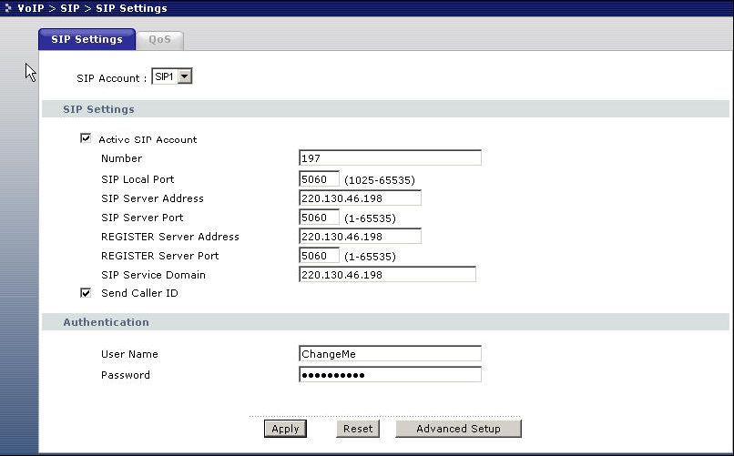

96 96

97 1. Setup WEB GUI VoIP, enter device A s number in the SIP number column. 2. Fill in device B s IP into SIP server address, Register server address as example. 3. Setup speed dial, put device B s information into the column. Setup--- Configuring SIP / VoIP related settings in device B 97
98 1. Setup WEB GUI VoIP, enter device B s number in the SIP number column. 2. Fill in device A s IP into SIP server address, Register server address as example. 3. Setup speed dial, put device A s information into the column. After completing the setting, you can dial #01 from the phone under device A, then the phone under device B will ring. Phone port settings Prestige allows you to configure the volume and echo cancellation setting for each individual phone port. 98
99 To configure the phone port setting, please follow the below step. Step 1. Open the web browser from your workstation to connect to the Prestige by entering the Management IP address of the Prestige. The default management IP of Prestige is Step 2. Enter the administrator password appear on the page of login and click on login. The default is '1234' Step 3. On the left column click on VoIP -> Phone -> Analog Phone -> Advanced Setup to bring you to voice function menu. Step 4. Change the phone port parameter as you desired and click Apply when you are finish to save and let the setting to take effect. Each field's detail description is listed below. Label Speaking Volume Listening Volume Description Use this field to set the loudness that the Prestige uses for the speech signal that it sends to the peer device. -1 is the quietest and 1 is the loudest. Use this field to set the loudness that the Prestige uses for the speech signal that it receives from the peer device and sends to your phone. -1 is the 99
100 quietest and 1 is the loudest. G.168 Active Select this check box to cancel the echo caused by the sound of your voice reverberating in the telephone receiver while you talk. VAD Support Dialing Interval Apply Reset Select this check box to use Voice Activity Detection (VAD) to reduce the bandwidth that a call uses. The Prestige will generate and send comfort noise when you are not talking. When you are dialing a telephone number the Prestige waits this long after you stop pressing the buttons before initiating the call. Select how many seconds you want the Prestige to wait after the last input on the telephone s keypad before dialing (making) a call. Click Apply to save your changes back to the Prestige. Click Reset to begin configuring this screen afresh. Advanced voice settings configuration Click VoIP in the navigation panel and then SIP to open the SIP Settings. Select a SIP account and then click Advanced Settings to display the following screen. Advanced voice settings configuration allows user to modify SIP server related settings, RTP port range, preferred compression type (codec), DTMF type and Message Waiting Indication (MWI) 100
101 Each field's detail description of the page is listed below. Label SIP Account Description This read-only field displays the number of the SIP account that you are configuring. The changes that you save in this page affect the Prestige s settings with the SIP account displayed here.. 101
102 URL Type Select SIP to have the Prestige include the domain name with the SIP number in the SIP messages that it sends. Select TEL to have the Prestige use the SIP number without a domain name in the SIP messages that it sends. Expiration Duration Register Re-send Timer Session Expires Min-SE This field sets how long an entry remains registered with the SIP register server. After this time period expires, the SIP register server deletes the Prestige s entry from the database of registered SIP numbers. The register server can use a different time period. The Prestige sends another registration request after half of this configured time period has expired. Use this field to set how long the Prestige waits before sending a repeat registration request if a registration attempt fails or there is no response from the registration server. Use this field to set the longest time that the Prestige will allow a SIP session to remain idle (without traffic) before dropping it When two SIP devices negotiate a SIP session, they must negotiate a common expiration time for idle SIP sessions. This field sets the shortest expiration time that the Prestige will accept.? The Prestige checks the session expiration values of incoming SIP INVITE requests against the minimum session expiration value that you configure here. If the session expiration of an incoming INVITE request is less than the value you configure here, the Prestige negotiates with the other SIP device to increase the session expiration value to match the Prestige s minimum session expiration value. RTP Port Range DTMF Mode Real time Transport Protocol is used to handle voice data transfer. Use this field to configure the Prestige s listening port range for RTP traffic. Leave these fields set to the defaults if you were not given a range of RTP ports to use. The Dual Tone Multi-Frequency (DTMF) mode sets how the Prestige handles the tones that your telephone makes when you push its buttons. It is recommended that you use the same mode that your VoIP service provider uses. 102
103 Select RFC 2833 to send the DTMF tones in RTP packets. Select PCM (Pulse Code Modulation) to include the DTMF tones in the voice data stream. This method works best when you are using a codec that does not use compression (like G.711). Codecs that use compression (like G.729) could distort the tones. Select SIP INFO to send the DTMF tones in SIP messages. MWI (Message Waiting Indication) Expiration Time Call Forward Table Back Apply Enable Message Waiting Indication (MWI) to have your phone give you a message waiting (beeping) dial tone when you have a voice message(s). Your voice service provider must have a messaging system that supports this feature. Use this field to set how long the SIP server should continue providing the message waiting service after receiving a SIP SUBSCRIBE message from the Prestige. The SIP server stops providing the message waiting service if it has not received another SIP SUBSCRIBE message from the Prestige before this time period expires. Select which call forwarding table you want the Prestige to use to block or redirect calls. You can use a different call forwarding table for each SIP account or use the same call forwarding table for both. Click Back to return to the previous screen without saving configuration changes. Click Apply to save your changes back to the Prestige. Phone book Speed dial Prestige allows you to configure up to 10 SIP numbers in the phone book for speed dial. 103
104 To configure phone book for speed dial please follow the below step. Step 1. Open the web browser from your workstation to connect to the Prestige by entering the Management IP address of the Prestige. The default management IP of Prestige is Step 2. Enter the administrator password appear on the page of login and click on login. The default is '1234' Step 3. On the left column click on VoIP -> Phone Book -> Speed Dial to bring you to Speed Dial page to enter speed dial configuration page. Step 4. Select the entry number you wish to add to the phone book by the entry selector located under add new entry category on the speed dial field. Step 5. Fill in the SIP number of the remote party and a descriptive name and click on the radio button to select either to use proxy or entering static IP or URL remote peer. Step 6. Click on Add button when you are finish to add the entry to the phone book. Each field's detail description of the page is listed below. 104
105 Label Speed Dial Description Select a speed dial key combination from the drop-down list box. SIP Number Enter the SIP number of the party that you will call (use the number or text that comes before symbol in a full SIP URI). You can use up to 127 ASCII characters. Name Type Enter a descriptive name to identify the party that you will use this entry to call. You can use up to 127 ASCII characters. Select Use Proxy if calls to this party use your SIP account configured in the VoIP screen. Select Non-Proxy (Use IP or URL) if calls to this party use a different SIP server or go directly to the callee s VoIP phone (IP-to-IP). Enter the SIP server s or the party s IP address or domain name (up to 127 ASCII Extended set characters). Add Speed Dial Phone Book Speed Dial Name Click this button to save the entry in the speed dial phone book. The speed dial entry displays in the Speed Dial Phone Book section of the screen. This section of the screen displays the currently saved speed dial entries. You can configure up to 10 entries and use them to make calls. This is the entry s speed dial key combination. Press this key combination on a telephone attached to the Prestige in order to call the party named in this entry. This is the descriptive name of the party that you will use this speed dial entry to call. SIP Number This is the SIP number of the party that you will call. Type Delete Edit Clear This field displays Use Proxy if calls to this party use one of your SIP accounts. This field displays the SIP server s or the party s IP address or domain name if calls to this party do not use one of your SIP accounts. Click this button to remove an entry from the speed dial phonebook. Click this button to change the speed dial entry. The speed dial entry displays in the Add New Entry section of the screen where you can edit it. Click this button to remove all of the entries from the speed dial phonebook. 105
106 Voice Common Settings Click VoIP -> Phone -> Common to display the following screen. Use this screen to configure Immediate Dial Click VoIP -> Phone -> Region to display the following screen. Use this screen to configure VoIP Common Settings. Label Region Settings Immediate Dial Description Use the drop-down list box to select the country where your Prestige is located. Use these fields to specify phone numbers to which the Prestige will always send calls through the regular phone service without the need of dialing a 106
107 prefix number. These numbers must be for phones on the PSTN (not VoIP phones). Use this field to set how the Prestige handles supplementary phone services (call hold, call waiting, call transfer and three-way conference calls). Select the mode that your voice service provider supports. Call Service Mode Select Europe Type to use the supplementary phone services in European mode. Select USA Type to use the supplementary phone services American mode. See your User's Guide for supplementary phone service details. To take full advantage of the supplementary phone services available though the Prestige's phone ports, you may need to subscribe to the services from your voice service provider. Back Apply Click Back to return to the previous screen. Click Apply to save your changes back to the Prestige. Voice - QoS setup Quality of Service (QoS) refers to both a network's ability to deliver data with minimum delay, and the networking methods used to provide bandwidth for real-time multimedia applications. Click VoIP -> SIP -> QoS to display the following screen. 107
108 Each field's detail description of the page is listed below. Label SIP TOS Priority RTP TOS Priority Voice VLAN ID Description Type a priority for voice transmissions. The Prestige applies Type of Service priority tags with this priority to voice traffic that it transmits. Type a priority for voice transmissions. The Prestige applies Type of Service priority tags with this priority to RTP traffic that it transmits. Enable VLAN tagging if the Prestige needs to be a member of a VLAN group in order to communicate with the SIP server. Your LAN and gateway must also be set up to use VLAN tags. Some switches also give priority to voice traffic based on its VLAN tag. Type the VLAN ID (VID) from 1 to 4095 for the Prestige to add to voice Ethernet frames that it sends out to the network. Disable VLAN tagging if the Prestige does not need to be a member of a VLAN group to communicate with the SIP server. Apply Click Apply to save your changes back to the Prestige. 108
109 Call Forwarding setup Call forwarding function allows users to determine handling of incoming calls. For example, a user may wish to decide that all incoming calls will ring his cell phone as well. The following screenshot shows how users can use this screen to configure the Prestige to block or redirect calls. You can configure a different call forwarding table for each SIP account or use the same call forwarding table for both. Unconditional Forward to Number Enable this feature to have the Prestige forward incoming calls to the number that you configure. Busy Forward to Number Enable this feature to have the Prestige forward incoming calls to the number that you configure when your SIP account has a call connected. 109
110 No Answer Forward to Number Enable this feature to have the Prestige forward incoming calls to the number that you configure whenever you do not answer the call after a specific time period. Each field's detail description of the page is listed below. Label Description Table Number Select which call forwarding table you want to configure. You can configure a different call forwarding table for each SIP account or use the same call forwarding table for both. The following applies to the number fields in this screen. For a SIP number, use the number or text that comes before symbol in a full SIP URI. Forward to Number Setup Unconditional Forward to Number Busy Forward to Number No Answer Forward to Number No Answer Waiting Time Advanced These are the global call forwarding settings that define the default action to take on incoming calls that do not match any of the Advanced Setup call forwarding entries. Enable this feature to have the Prestige forward all incoming calls to the number that you configure regardless of whether or not the phone(s) connected to the phone port(s) is busy. Enable this feature to have the Prestige forward incoming calls to the number that you configure when the phone(s) connected to the phone port(s) is busy. With call waiting a second call is only forwarded after being rejected. Enable this feature to have the Prestige forward incoming calls to the number that you configure whenever you do not answer the call after a specific time period. Set how long the Prestige should let a call ring before considering the call unanswered. Configure Advanced Setup call forwarding entries to have the Prestige 110
111 Setup Activate Incoming Call Number Forward to Number Condition perform specific actions on calls from specific numbers. If a caller s number does not match the Incoming Call Number of any of these entries, the Prestige performs the default action configured in the Forward to Number Setup section. Select this check box to turn on an call forwarding entry. You can set the Prestige to take a particular action on incoming calls from a number that you specify here. You can set the Prestige to forward incoming calls to a number that you specify here. Select under what circumstances you want the Prestige to use this call forwarding entry. Select Unconditional to have the Prestige immediately forward any calls from the number specified in the Incoming Call Number field to the number in the Forward to Number field. Select Busy to have the Prestige forward any calls from the number specified in the Incoming Call Number field to the number in the Forward to Number field when your SIP account has a call connected. Select No Answer to have the Prestige forward any calls from the number specified in the Incoming Call Number field to the number in the Forward to Number field when the No Answer Waiting Time period expires (whether or not the no answer feature is enabled in the Forward to Number Setup section). Select Block to have the Prestige reject calls from the number specified in the call forwarding entry. Select Accept to have the Prestige allow calls from the number specified in the Incoming Call Number field. Call Hold setup Prestige allows user agent to interrupt communications on an existing call. 111
112 Call hold allows you to put a call (A) on hold by pressing the flash key. If you have another call, press the flash key to switch back and forth between caller A and B by putting either one on hold. Call Waiting setup This allows you to place a call on hold while you answer another incoming call on the same telephone number. If there is a second call to your telephone number, you will hear a call waiting tone. Scenario A calls B and start conversation C calls A In this scenario, there are 3 kinds of action available: Below call flow graphs could help you better understand the call waiting working mechanism. Scenario 1: If A presses flash key + 0, A will reject C. 112

113 Scenario 2: If A presses flash key + 1, A will disconnect B and answer C. Scenario 3: If A presses flash key + 2, A will put B on hold and answer C. 113
114 Three Way Conference setup Three Way Conference function makes it possible to set up a conference call with three subscribers all able to participate at the same time. To configure Three Way Conference, please follow the below steps: Step 1. A is on the phone talking with C, A press the flash key to put the caller on hold and get a dial tone. Step 2. Dial B phone number directly to make another call. Step 3. When the second call is answered, press the flash key and then press 3 to create a three-way conversation. Step 4. Hang up the phone to drop the connection. Step 5. If you want to separate the activated three-way conference into two individual connections (one is on-line, the other is on hold), press the flash key and press
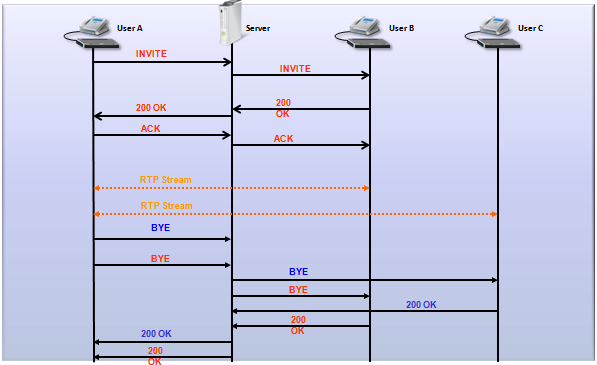
115 115

116 Call Transfer setup This feature allows transfer an incoming call (that you have answered) to another phone. Note: The primary call between user A and user B must be answered before transfer can be initiated. Three kinds of call transfer service available: Blind Transfer Consult On - Hold Transfer Attendant Transfer Application scenario 1: Blind Transfer A dial to B B off hook A and B conversation If user A does not want to communicate with user B or user C after call transfer, user A could choose Blind Transfer. 116
117 To active Blind Transfer please follow the below step: Step 1: A flash, B MOH (Music On Hold). Step 2: A dial *98# + C s number. Step 3: A hears the ring back tone Step 4: A on hook Step 5: C rings, B hear the ring back tone Step 6: C off hook, B and C start conversation Application scenario 2: Consult On - Hold Transfer A dial to B B off hook A and B conversation If user A wants to communicate with user C for a while, then drop the connection to let user B and user C keep communication, user A could choose Consult Transfer. To active Consult On - hold Transfer please follow the below step: Step 1: A flash, B MOH (Music On Hold). 117

118 Step 2: A dial *98# + C s Number. Step 3: C rings, A hears the ring back tone. Step 4: C off hook, A and C start conversation. Step 5: A on-hook. Step 6: B and C start conversation. Application scenario 3: Attendant Transfer A dials to B B off hook A and B start Conversation If user A wants to communicate with user C for a while, then drop the connection to let user B and user C keep communication, user A may also choose Attendant Transfer. To active Attendant Transfer please follow the below step: Step 1: A flash, B MOH (Music On Hold). Step 2: A dial to C. Step 3: C rings, A hears the ring back tone. 118

119 Step 4: C off hook, A and C start Conversation. Step 5: A flash + *98#. Step 6: B and C start conversation, A hears the busy tone. Internal Call This feature is ZyXEL proprietary implementation. When you have two phones attached to the P2602Rx phone ports, you just dial "####" on one of the two phones, another phone will ring. Call Fallback Call Fallback allows customer to set your P-2602R-D1A to automatically relay outgoing phone calls to PSTN network if the DSL line is unplugged or SIP account cannot be registered, or relay outgoing calls to IP network when PSTN line is unplugged. You may set up Call Fallback easily on web GUI: VoIP > Phone > Common Call Park / Call Pickup Call Park/Pickup function allows you to place a call on hold first, then it can be retrieved from another phone in 119
120 the system. For example, if you are on an active call at your phone, you can park the call by press *97# + park number. Someone on another phone in the system can then dial the call park number to pick-up the call. Note: The caller must still pay while the call is parked. When you park the call, you enter a number of your choice (Up to eight digits), which you must enter again when you pick up the call. If you do not enter the correct number, you cannot pickup the call. This means that only someone who knows the number you have chosen can pick up the call. You can have more than one call on hold at the same time, but you must give each call a different number. This example show you how to configure the Call Park and Call Pickup Phone Configuration: Press *97# + park number to park the call Press #97# + park number to pick-up the call Call Park Call Flow When a call has established between A and the caller: To Call Park the call please follow the below steps: Step 1: User A Press *97# + park number (5000) to park the call Step 2: Then A hang up the phone 120
 to pick up the call.")
121 Call Pickup Call Flow To pick up the call please only need to input #97# and the park number: In below graph, user B press #97# + park number (5000) to pick up the call. 121
122 Call Return With call return, you can place a call to the last number that called you (either answered or missed). The last incoming call can be through either SIP or PSTN. Two application scenario: 1. A missed a call from B. 2. A made a successful call with B. In both scenarios, user A only needs to pick up the phone and presses *66#, B will ring automatically. 122
. Use this feature to let you know where a call comes from before you answer it. Application Scenario: 1.")
123 Distinctive Ringing With the distinctive ring feature, you can assign different ringing tones to different incoming calls, based either on the number that calls you or from where the call originates (SIP, PSTN or internal). Use this feature to let you know where a call comes from before you answer it. Application Scenario: 1. Ring Selection by Incoming Number: Different call (from family/workmate/friend/vip) has the different ring. 2. Ring Selection by Incoming Line: If the phone number is not in the group, phone ring tone will be based on where it comes from. (SIP/PSTN/Internal). You may configure Distinctive Ring easily on web GUI: VoIP > Phone Book > Distinctive Ring Each filed is described in the following table: 123

124 Do Not Disturb (DND) This feature allows you to set your phone not to ring when someone calls you. You can set each phone independently using its keypad, or configure global setting for all phones using the command line. How to configure DND on phone keypad? *95# Enable Do Not Disturb #95# Disable Do not Disturb *95#SIP Number*Active Timer# For example, if you need to block the call from 3333 (SIP Number) for 2 hours, just need to input *95#3333*2# 124
125 on phone keypad, it will implement this feature. Hot Line (Auto Dial) This feature enables the device to make a call to a predefined number as soon as the phone is off hook. Application Scenario: 1. Configure the Hot Line setting first. 2. A lifts phone. 3. A will automatically dial the preconfigured number. You may configure Hot Line (Auto Dial) easily on web GUI: VoIP > Phone > Analog Phone > Advanced Or by CLI command setting. Below CLI commands are used to configure the Hot Line: voice config fxs autodial enable // Enable Hot Line (Auto Dial) Feature voice config fxs autodial number // Set Hot Line number voice config fxs diallonginterval // Set the interval between phone picking up and dialing out For example, if you want SIP1 phone call automatically after the phone is off hook and without pressing any button on the phone keypad in 5 seconds. Below CLI command could implement it: ras> voice config fxs index 1 ras> voice config fxs autodialenable 1 enable ras> voice config fxs autodialnumber ras> voice config fxs diallonginterval 1 5 ras> voice config fxs save 1 125
 presses flash or reserve key to put a call on hold, the peer side (B) will receive INVITE packet with zero IP address in SDP to inform there is no need to")
126 Music on hold This feature allows you to put a call on hold and have the other person hear a piece of audio (music, speech, etc.) you previously recorded. Application Scenarios: When one side (A) presses flash or reserve key to put a call on hold, the peer side (B) will receive INVITE packet with zero IP address in SDP to inform there is no need to send RTP out any more (RFC2543) or change the attribute field in SDP to recvonly (RFC3261). Phone A generates pre-recorded music from IVR to phone B directly. You may configure Music on Hold feature easily on P2602R-D1A web GUI: VoIP > SIP > SIP setting > Advanced In this graph, Device A has enabled Music on Hold function. Thus when A and B are on a call, and if A holds the call, B will hear the music tone. 126
, lighting a")
127 MWI Message Waiting Indication is a common feature of telephone networks. It typically involves an audible or visible indication that messages are waiting, such as playing a special dial tone (which in telephone networks is called message-waiting dial tone), lighting a light or indicator on the phone, displaying icons or text, or some combination these. Enable Message Waiting Indication (MWI) enables your phone to give you a message waiting (beeping) dial tone when you have a voice message(s). Your VoIP service provider must have a messaging system that sends message waiting status SIP packets as defined in RFC MWI Call flow: 127

128 You may configure MWI feature easily on P2602R-D1A web GUI: VoIP > SIP > SIP setting > Advanced Caller ID enable/disable This feature is used for user to display or hide his Caller ID for a specific outgoing call. Phone configuration settings: User need to press *82phone_number to show his Caller ID during a call, or press *67phone_number to hide his Caller ID during a call. Application scenario: User A wants to hide his phone number for outgoing call, therefore should press *67 plus the phone number. Early Media Early media allows the Caller to listen to some music being played from the remote side (e.g. be from the media server or from the callee) instead of a locally generated ringback tone before the callee answers the phone. Early media call flow: 128

129 Enable early media in web configuration: VOIP>SIP>SIP settings>advanced. 129

130 Country Code Some VoIP parameters/settings have different values according to which country you live in now. Like tone, ring, flash time etc... It is a lot of trouble to change it one by one once you relocate to a different country. This feature allows you to change these parameters easily. Application scenario: User only needs to choose corresponding country code to implement all these changes when moving from one country to another. Country Code configuration in Web GUI: VoIP>Phone>Region. Choose the Region Settings: Caution: When Region Settings are changed, you need to reboot the device for the settings to take effect. FAQ ZyNOS FAQ What is ZyNOS? ZyNOS is ZyXEL's proprietary Network Operating System. It is the platform on all Prestige routers that delivers network services and applications. It is designed in a modular fashion so it is easy for developers to add 130
P-2602HWNLI. Support Notes. Version 3.40 March. 2006
 P-2602HWNLI Support Notes Version 3.40 March. 2006 Index Application Notes...9 General Application Notes...9 Internet Connection...9 Setup the Prestige as a DHCP Relay...13 Configure an Internal Server
P-2302HWUDL-P1. Support Notes. 802.11g Wireless VoIP Station Gateway. with DECT Base Station
 P-2302HWUDL-P1 802.11g Wireless VoIP Station Gateway with DECT Base Station Support Notes Version 3.60 Oct. 2007 INDEX Application Notes... 6 General Application Notes...6 Internet Connection... 6 Setup
Prestige 202H Plus. Quick Start Guide. ISDN Internet Access Router. Version 3.40 12/2004
 Prestige 202H Plus ISDN Internet Access Router Quick Start Guide Version 3.40 12/2004 Table of Contents 1 Introducing the Prestige...3 2 Hardware Installation...4 2.1 Rear Panel...4 2.2 The Front Panel
Prestige 310. Cable/xDSL Modem Sharing Router. User's Guide Supplement
 Prestige 310 Cable/xDSL Modem Sharing Router User's Guide Supplement Domain Name Support Enhanced WAN Setup Remote Node Support PPPoE Support Enhanced Unix Syslog Setup Firmware and Configuration Files
P-660R-T1/T3/T7 INDEX. ZyNOS FAQ. ZyXEL... Support Notes Version 1.0 June.12th 2005
 P-660R-T1/T3/T7 Support Notes Version 1.0 June.12th 2005 INDEX ZyNOS FAQ 1. What is ZyNOS? 2. How do I access the Prestige SMT menu? 3. What is the default console port baud rate? Moreover, how do I change
Prestige 324. Prestige 324. Intelligent Broadband Sharing Gateway. Version 3.60 January 2003 Quick Start Guide
 Prestige 324 Intelligent Broadband Sharing Gateway Version 3.60 January 2003 Quick Start Guide 1 Introducing the Prestige The Prestige is a broadband sharing gateway with a built-in four-port 10/100 Mbps
Prestige 792H. G.SHDSL 4-port Security Gateway. Compact Guide Version 3.40(BZ.0) March 2004
 March 2004") G.SHDSL 4-port Security Gateway Compact Guide Version 3.40(BZ.0) March 2004 Table of Contents 1 Introducing the Prestige... 3 1.1 Certifications... 3 2 Hardware... 4 2.1 Rear Panel Connections... 4 2.2
G.SHDSL 4-port Security Gateway Compact Guide Version 3.40(BZ.0) March 2004 Table of Contents 1 Introducing the Prestige... 3 1.1 Certifications... 3 2 Hardware... 4 2.1 Rear Panel Connections... 4 2.2
Prestige 324 Quick Start Guide. Prestige 324. Intelligent Broadband Sharing Gateway. Version V3.61(JF.0) May 2004 Quick Start Guide
 May 2004 Quick Start Guide") Prestige 324 Intelligent Broadband Sharing Gateway Version V3.61(JF.0) May 2004 Quick Start Guide 1 1 Introducing the Prestige The Prestige is a broadband sharing gateway with a built-in four-port 10/100
Prestige 324 Intelligent Broadband Sharing Gateway Version V3.61(JF.0) May 2004 Quick Start Guide 1 1 Introducing the Prestige The Prestige is a broadband sharing gateway with a built-in four-port 10/100
P-660R-Tx v2 Series. ADSL2+ Router. Support Notes
 P-660R-Tx v2 Series ADSL2+ Router Support Notes Version3.40 Jan. 2006 FAQ...4 ZyNOS FAQ...4 1. What is ZyNOS?...4 2. How do I access the P-660R-Tx v2 Command Line Interface (CLI)?...4 3. How do I update
Prestige 623R-T. Quick Start Guide. ADSL Dual-link Router. Version 3.40
 Prestige 623R-T ADSL Dual-link Router Quick Start Guide Version 3.40 February 2004 Introducing the Prestige The Prestige 623R-T ADSL Dual-link Router is the ideal all-in-one device for small networks connecting
ZyWALL 5. Internet Security Appliance. Quick Start Guide Version 3.62 (XD.0) May 2004
 May 2004") ZyWALL 5 Internet Security Appliance Quick Start Guide Version 3.62 (XD.0) May 2004 Introducing the ZyWALL The ZyWALL 5 is the ideal secure gateway for all data passing between the Internet and the LAN.
ZyWALL 5 Internet Security Appliance Quick Start Guide Version 3.62 (XD.0) May 2004 Introducing the ZyWALL The ZyWALL 5 is the ideal secure gateway for all data passing between the Internet and the LAN.
Prestige 2802HWL-Ix. Support Notes. Version 3.40 Jun. 2007
 Prestige 2802HWL-Ix Support Notes Version 3.40 Jun. 2007 Index Application Notes...9 General Application Notes...9 Internet Connection...9 Setup the Prestige as a DHCP Relay...13 Configure an Internal
Prestige 650R-31/33 Read Me First
 Prestige 650R-31/33 Read Me First Prestige Rear Panel Connections PORT DSL CONSOLE LAN 10/100M POWER Connect to a telephone jack using a telephone wire. CONNECTION Connect to a serial port (COM port) on
P-660R-TxC Series. ADSL2+ Access Router. Quick Start Guide
 P-660R-TxC Series ADSL2+ Access Router Quick Start Guide Version 3.40 Edition 1 2/2006 Overview The P-660R-TxC ADSL2+ access router is the ideal device for small networks connecting to the Internet via
Chapter 12 Supporting Network Address Translation (NAT)
") [Previous] [Next] Chapter 12 Supporting Network Address Translation (NAT) About This Chapter Network address translation (NAT) is a protocol that allows a network with private addresses to access information
[Previous] [Next] Chapter 12 Supporting Network Address Translation (NAT) About This Chapter Network address translation (NAT) is a protocol that allows a network with private addresses to access information
ADSL 2/2+ Gateway with 802.11g Wireless Compact Guide
 Series ADSL 2/2+ Gateway with 802.11g Wireless Compact Guide Version 3.40 March 2004 Table of Contents 1 Introducing the Prestige...3 2 Hardware...4 2.1 Rear Panel Connections...4 2.2 The Front Panel LEDs...5
Prestige 660HW Series. Prestige 660H Series. Compact Guide Version 3.40 September 2004
 Prestige 660HW Series ADSL 2+ 4-Port Gateway with 802.11g Wireless Prestige 660H Series ADSL 2+ 4-Port Gateway Compact Guide Version 3.40 September 2004 Table of Contents 1 Introducing the Prestige...4
Chapter 2 Connecting the FVX538 to the Internet
 Chapter 2 Connecting the FVX538 to the Internet Typically, six steps are required to complete the basic connection of your firewall. Setting up VPN tunnels are covered in Chapter 5, Virtual Private Networking.
TW100-BRV204 VPN Firewall Router
 TW100-BRV204 VPN Firewall Router Cable/DSL Internet Access 4-Port Switching Hub User's Guide Table of Contents CHAPTER 1 INTRODUCTION... 1 TW100-BRV204 Features... 1 Package Contents... 3 Physical Details...
TW100-BRF114 Firewall Router. User's Guide. Cable/DSL Internet Access. 4-Port Switching Hub
 TW100-BRF114 Firewall Router Cable/DSL Internet Access 4-Port Switching Hub User's Guide Table of Contents CHAPTER 1 INTRODUCTION...1 TW100-BRF114 Features...1 Package Contents...3 Physical Details...
UIP1868P User Interface Guide
 UIP1868P User Interface Guide (Firmware version 0.13.4 and later) V1.1 Monday, July 8, 2005 Table of Contents Opening the UIP1868P's Configuration Utility... 3 Connecting to Your Broadband Modem... 4 Setting
Load Balancer LB-2. User s Guide
 Load Balancer LB-2 User s Guide TABLE OF CONTENTS 1: INTRODUCTION...1 Internet Features...1 Other Features...3 Package Contents...4 Physical Details...4 2: BASIC SETUP...8 Overview...8 Procedure...8 3:
Load Balancing Router. User s Guide
 Load Balancing Router User s Guide TABLE OF CONTENTS 1: INTRODUCTION... 1 Internet Features... 1 Other Features... 3 Package Contents... 4 Physical Details... 4 2: BASIC SETUP... 8 Overview... 8 Procedure...
LevelOne. User Manual. FBR-1430 VPN Broadband Router, 1W 4L V1.0
 LevelOne FBR-1430 VPN Broadband Router, 1W 4L User Manual V1.0 Table of Contents CHAPTER 1 INTRODUCTION... 1 VPN BROADBAND ROUTER FEATURES... 1 Internet Access Features... 1 Advanced Internet Functions...
Broadband Router ALL1294B
 Broadband Router ALL1294B Broadband Internet Access 4-Port Switching Hub User's Guide Table of Contents CHAPTER 1 INTRODUCTION... 1 Broadband Router Features... 1 Package Contents... 3 Physical Details...
Broadband ADSL2+ Modem DM111PSPv2
 Broadband ADSL2+ Modem DM111PSPv2 User Manual 350 East Plumeria Drive San Jose, CA 95134 USA August 2011 202-10913-01 v1.0 2011 NETGEAR, Inc. All rights reserved No part of this publication may be reproduced,
Multi-Homing Security Gateway
 Multi-Homing Security Gateway MH-5000 Quick Installation Guide 1 Before You Begin It s best to use a computer with an Ethernet adapter for configuring the MH-5000. The default IP address for the MH-5000
Prestige 314 Read Me First
 Prestige 314 Read Me First Console WAN 10M PORT Prestige Rear Panel Connections CONNECTION Use an RS-232 console cable. Use the cable that came with your broadband modem. LAN 10/100M Port Number COMPUTER
Chapter 3 Connecting the Router to the Internet
 Chapter 3 Connecting the Router to the Internet This chapter describes how to set up the router on your Local Area Network (LAN) and connect to the Internet. It describes how to configure your DG834GT
P-660 series. Support Notes. (For P-660R/H/HW-T1/T3/T7)
") P-660 series Support Notes (For P-660R/H/HW-T1/T3/T7) Version1.0 Sep. 2005 INDEX...5 ZyNOS FAQ...5 1. What is ZyNOS?...5 2. How do I access the Prestige SMT menu?...5 3. What is the default console port
P-660 series Support Notes (For P-660R/H/HW-T1/T3/T7) Version1.0 Sep. 2005 INDEX...5 ZyNOS FAQ...5 1. What is ZyNOS?...5 2. How do I access the Prestige SMT menu?...5 3. What is the default console port
Prestige 660R-6x Read Me First
 Prestige 660R-6x Read Me First Prestige Rear Panel Connections DSL PORT CONNECTION Connect the DSL port on the Prestige to the wall jack using the included DSL cable (telephone wire). Connect the micro
Chapter 1 Configuring Basic Connectivity
 Chapter 1 Configuring Basic Connectivity This chapter describes the settings for your Internet connection and your wireless local area network (LAN) connection. When you perform the initial configuration
BR-6624. Load Balancing Router. Manual
 BR-6624 Load Balancing Router Manual TABLE OF CONTENTS 1: INTRODUCTION...1 Internet Features...1 Other Features...3 Package Contents...4 Physical Details...4 2: BASIC SETUP...8 Overview...8 Procedure...8
Broadband Phone Gateway BPG510 Technical Users Guide
 Broadband Phone Gateway BPG510 Technical Users Guide (Firmware version 0.14.1 and later) Revision 1.0 2006, 8x8 Inc. Table of Contents About your Broadband Phone Gateway (BPG510)... 4 Opening the BPG510's
Chapter 4 Customizing Your Network Settings
 . Chapter 4 Customizing Your Network Settings This chapter describes how to configure advanced networking features of the Wireless-G Router Model WGR614v9, including LAN, WAN, and routing settings. It
ZyWALL 35. Support Notes. Security Appliance. Version 4.03 Sep. 2007
 ZyWALL 35 Security Appliance Support Notes Version 4.03 Sep. 2007 INDEX Application Notes...12 Seamless Incorporation into your network...12 Using Transparent (Bridge Mode) Firewall...12 Internet Connection...17
DSL-G604T Install Guides
 Internet connection with NAT...2 Internet connection with No NAT, IP Un-number...6 Port Forwarding...12 Filtering & Firewall Setup...20 Access Control... 21 DMZ Setup... 26 Allow Incoming Ping... 27 How
3.1 RS-232/422/485 Pinout:PORT1-4(RJ-45) RJ-45 RS-232 RS-422 RS-485 PIN1 TXD PIN2 RXD PIN3 GND PIN4 PIN5 T+ 485+ PIN6 T- 485- PIN7 R+ PIN8 R-
 RJ-45 RS-232 RS-422 RS-485 PIN1 TXD PIN2 RXD PIN3 GND PIN4 PIN5 T+ 485+ PIN6 T- 485- PIN7 R+ PIN8 R-") MODEL ATC-2004 TCP/IP TO RS-232/422/485 CONVERTER User s Manual 1.1 Introduction The ATC-2004 is a 4 Port RS232/RS485 to TCP/IP converter integrated with a robust system and network management features
MODEL ATC-2004 TCP/IP TO RS-232/422/485 CONVERTER User s Manual 1.1 Introduction The ATC-2004 is a 4 Port RS232/RS485 to TCP/IP converter integrated with a robust system and network management features
Firewall VPN Router. Quick Installation Guide M73-APO09-380
 Firewall VPN Router Quick Installation Guide M73-APO09-380 Firewall VPN Router Overview The Firewall VPN Router provides three 10/100Mbit Ethernet network interface ports which are the Internal/LAN, External/WAN,
Multifunctional Broadband Router User Guide. Copyright Statement
 Copyright Statement is the registered trademark of Shenzhen Tenda Technology Co., Ltd. Other trademark or trade name mentioned herein are the trademark or registered trademark of above company. Copyright
Broadband Router ESG-103. User s Guide
 Broadband Router ESG-103 User s Guide FCC Warning This equipment has been tested and found to comply with the limits for Class A & Class B digital device, pursuant to Part 15 of the FCC rules. These limits
Chapter 1 Connecting Your Router to the Internet
 Chapter 1 Connecting Your Router to the Internet This chapter describes how to configure your DG834N RangeMax TM NEXT Wireless ADSL2+ Modem Router Internet connection.when you perform the initial configuration
Configuring a BANDIT Product for Virtual Private Networks
 encor! enetworks TM Version A, March 2008 2013 Encore Networks, Inc. All rights reserved. Configuring a BANDIT Product for Virtual Private Networks O ne of the principal features in the BANDIT family of
FBR-4000. Multi-WAN VPN Router. User Manual
 FBR-4000 Multi-WAN VPN Router User Manual V1.0 TABLE OF CONTENTS 1: INTRODUCTION... 1 INTERNET FEATURES... 1 OTHER FEATURES... 3 PACKAGE CONTENTS... 4 PHYSICAL DETAILS... 4 Front Panel... 4 Rear Panel...
V101 SIP VoIP Telephone Adaptor User Manual V1.1m
 V101 SIP VoIP Telephone Adaptor User Manual V1.1m Quick Guide Step 1: Broadband (ADSL/Cable Modem) Connections for V101 A. Connect V101 LAN port to ADSL NAT Router as the following connection. B. Connect
BR-6104K / BR-6104KP Fast Ethernet Broadband Router User s Manual
 BR-6104K / BR-6104KP Fast Ethernet Broadband Router User s Manual 1 Introduction... 4 Features... 4 Minimum Requirements... 4 Package Content... 4 Note... 4 Get to know the Broadband Router... 4 Back Panel...
 Setup The Setup screen is the first screen you will see when accessing the Gateway. Most users will be able to configure the Gateway and get it working properly using only the settings on this screen.
Prestige 2302R Series
 VoIP Station Gateway Quick Start Guide Version 3.60 6/2005 Overview This Quick Start Guide covers the Prestige (P2302R) and (P2302RL) models. It explains how to use your Prestige to make phone calls through
Multi-Homing Dual WAN Firewall Router
 Multi-Homing Dual WAN Firewall Router Quick Installation Guide M73-APO09-400 Multi-Homing Dual WAN Firewall Router Overview The Multi-Homing Dual WAN Firewall Router provides three 10/100Mbit Ethernet
AMG1001-T Series. AMG1011-T Series. User s Guide. Quick Start Guide. ADSL2+ 1-port Gateway. ADSL2+ 1-port Ethernet/USB Gateway. Default Login Details
 AMG1001-T Series ADSL2+ 1-port Gateway AMG1011-T Series ADSL2+ 1-port Ethernet/USB Gateway Version 1.00 Edition 1, 07/2013 Quick Start Guide User s Guide Default Login Details IP Address http://192.168.1.1
your Gateway Windows network installationguide 802.11b wireless series Router model WBR-100 Configuring Installing
 your Gateway Windows network installationguide 802.11b wireless series Router model WBR-100 Installing Configuring Contents 1 Introduction...................................................... 1 Features...........................................................
Pre-lab and In-class Laboratory Exercise 10 (L10)
") ECE/CS 4984: Wireless Networks and Mobile Systems Pre-lab and In-class Laboratory Exercise 10 (L10) Part I Objectives and Lab Materials Objective The objectives of this lab are to: Familiarize students
ECE/CS 4984: Wireless Networks and Mobile Systems Pre-lab and In-class Laboratory Exercise 10 (L10) Part I Objectives and Lab Materials Objective The objectives of this lab are to: Familiarize students
AudioCodes. MP-20x Telephone Adapter. Frequently Asked Questions (FAQs)
") AudioCodes MP-20x Telephone Adapter Frequently Asked Questions (FAQs) Page 2 AudioCodes Customer Support Table of Contents Introduction... 6 Frequently Asked Questions... 7 Web Access... 7 Q1: How must
AudioCodes MP-20x Telephone Adapter Frequently Asked Questions (FAQs) Page 2 AudioCodes Customer Support Table of Contents Introduction... 6 Frequently Asked Questions... 7 Web Access... 7 Q1: How must
CPEi 800/825 Series. User Manual. * Please see the Introduction Section
 CPEi 800/825 Series User Manual * Please see the Introduction Section Contents Introduction...iii Chapter 1: CPEi 800/825 User Guide Overview... 1-1 Powerful Features in a Single Unit... 1-2 Front of the
DSL-2600U. User Manual V 1.0
 DSL-2600U User Manual V 1.0 CONTENTS 1. OVERVIEW...3 1.1 ABOUT ADSL...3 1.2 ABOUT ADSL2/2+...3 1.3 FEATURES...3 2 SPECIFICATION...4 2.1 INDICATOR AND INTERFACE...4 2.2 HARDWARE CONNECTION...4 2.3 LED STATUS
Chapter 9 Monitoring System Performance
 Chapter 9 Monitoring System Performance This chapter describes the full set of system monitoring features of your ProSafe Dual WAN Gigabit Firewall with SSL & IPsec VPN. You can be alerted to important
Broadband Router User s Manual
 Broadband Router User s Manual Table of Contents Chapter 1 Introduction...4 1.1 The Broadband Router......4 1.2 Physical Features of Broadband Router...4 1.3 Non-Physical Features of Broadband Router..
Load Balance Router R258V
 Load Balance Router R258V Specification Hardware Interface WAN - 5 * 10/100M bps Ethernet LAN - 8 * 10/100M bps Switch Reset Switch LED Indicator Power - Push to load factory default value or back to latest
Chapter 2 Preparing Your Network
 Chapter 2 Preparing Your Network This document describes how to prepare your network to connect to the Internet through a router and how to verify the readiness of your broadband Internet service from
User s Manual TCP/IP TO RS-232/422/485 CONVERTER. 1.1 Introduction. 1.2 Main features. Dynamic DNS
 MODEL ATC-2000 TCP/IP TO RS-232/422/485 CONVERTER User s Manual 1.1 Introduction The ATC-2000 is a RS232/RS485 to TCP/IP converter integrated with a robust system and network management features designed
Chapter 1 Configuring Internet Connectivity
 Chapter 1 Configuring Internet Connectivity This chapter describes the settings for your Internet connection and your wireless local area network (LAN) connection. When you perform the initial configuration
WEB CONFIGURATION. Configuring and monitoring your VIP-101T from web browser. PLANET VIP-101T Web Configuration Guide
 WEB CONFIGURATION Configuring and monitoring your VIP-101T from web browser The VIP-101T integrates a web-based graphical user interface that can cover most configurations and machine status monitoring.
P-660H-Tx v2 Series. ADSL2+ 4-port Gateway. Support Notes
 P-660H-Tx v2 Series ADSL2+ 4-port Gateway Support Notes Version3.40 Feb. 2007 FAQ...4 ZyNOS FAQ...4 1. What is ZyNOS?...4 2. What s Multilingual Embedded Web Configurator?...4 3. How do I access the P-660H-Tx
Guideline for setting up a functional VPN
 Guideline for setting up a functional VPN Why do I want a VPN? VPN by definition creates a private, trusted network across an untrusted medium. It allows you to connect offices and people from around the
Prestige 2602HW-C Series. Prestige 2602HWL-C Series
 Prestige 2602HW-C Series 802.11g Wireless ADSL VoIP IAD Prestige 2602HWL-C Series 802.11g Wireless ADSL VoIP IAD with Lifeline Quick Start Guide Version 3.40 3/2005 Prestige 2602HW Series Quick Start Guide
Protecting the Home Network (Firewall)
") Protecting the Home Network (Firewall) Basic Tab Setup Tab DHCP Tab Advanced Tab Options Tab Port Forwarding Tab Port Triggers Tab DMZ Host Tab Firewall Tab Event Log Tab Status Tab Software Tab Connection
Protecting the Home Network (Firewall) Basic Tab Setup Tab DHCP Tab Advanced Tab Options Tab Port Forwarding Tab Port Triggers Tab DMZ Host Tab Firewall Tab Event Log Tab Status Tab Software Tab Connection
ZyWALL 5. Support Notes. Security Appliance. Version 4.01 Jun. 2006
 ZyWALL 5 Security Appliance Support Notes Version 4.01 Jun. 2006 INDEX Application Notes...12 Seamless Incorporation into your network...12 Using Transparent (Bridge Mode) Firewall...12 Internet Connection...17
Chapter 7 Troubleshooting
 Chapter 7 Troubleshooting This chapter provides troubleshooting tips and information for your ProSafe VPN Firewall 200. After each problem description, instructions are provided to help you diagnose and
Vigor 2700 Series Firewall Router User s Guide
 Vigor 2700 Series Firewall Router User s Guide Version: 2.5 Date: 2007/03/19 Copyright 2006 All rights reserved. This publication contains information that is protected by copyright. No part may be reproduced,
P160S SIP Phone Quick User Guide
 P160S SIP Phone Quick User Guide Version 2.2 TABLE OF CONTENTS 1.0 INTRODUCTION... 1 2.0 PACKAGE CONTENT... 1 3.0 LIST OF FIGURES... 2 4.0 SUMMARY OF KEY FUNCTIONS... 3 5.0 CONNECTING THE IP PHONE... 4
Configuring SSL VPN on the Cisco ISA500 Security Appliance
 Application Note Configuring SSL VPN on the Cisco ISA500 Security Appliance This application note describes how to configure SSL VPN on the Cisco ISA500 security appliance. This document includes these
Chapter 10 Troubleshooting
 Chapter 10 Troubleshooting This chapter provides troubleshooting tips and information for your ProSafe Dual WAN Gigabit Firewall with SSL & IPsec VPN. After each problem description, instructions are provided
Chapter 8 Router and Network Management
 Chapter 8 Router and Network Management This chapter describes how to use the network management features of your ProSafe Dual WAN Gigabit Firewall with SSL & IPsec VPN. These features can be found by
Initial Access and Basic IPv4 Internet Configuration
 Initial Access and Basic IPv4 Internet Configuration This quick start guide provides initial and basic Internet (WAN) configuration information for the ProSafe Wireless-N 8-Port Gigabit VPN Firewall FVS318N
Innominate mguard Version 6
 Innominate mguard Version 6 Configuration Examples mguard smart mguard PCI mguard blade mguard industrial RS EAGLE mguard mguard delta Innominate Security Technologies AG Albert-Einstein-Str. 14 12489
Firewall Defaults and Some Basic Rules
 Firewall Defaults and Some Basic Rules ProSecure UTM Quick Start Guide This quick start guide provides the firewall defaults and explains how to configure some basic firewall rules for the ProSecure Unified
Note: these functions are available if service provider supports them.
 Key Feature New Feature Remote Maintenance: phone can be diagnosed and configured by remote. Zero Config: automated provisioning and software upgrading even through firewall/nat. Centralized Management:
ADSL MODEM. User Manual V1.0
 ADSL MODEM User Manual V1.0 CONTENTS 1.OVERVIEW... 3 1.1 ABOUT ADSL... 3 1.2 ABOUT ADSL2/2+... 3 1.3 FEATURES... 3 2 SPECIFICATION... 4 2.1 INTERFACE INTRODUCTION... 4 2.1.1 INDICATOR AND INTERFACE...
A Division of Cisco Systems, Inc. Broadband Router. with 2 Phone Ports. Voice Installation and Troubleshooting Guide RTP300. Model No.
 A Division of Cisco Systems, Inc. Broadband Router with 2 Phone Ports Voice Installation and Troubleshooting Guide Model No. RTP300 Copyright and Trademarks Specifications are subject to change without
N150 WiFi Router (N150R)
") Easy, Reliable & Secure N150 WiFi Router (N150R) User Manual 350 East Plumeria Drive San Jose, CA 95134 USA August 2012 202-11000-01 v1.0 Trademarks Brand and product names are trademarks or registered
Easy, Reliable & Secure N150 WiFi Router (N150R) User Manual 350 East Plumeria Drive San Jose, CA 95134 USA August 2012 202-11000-01 v1.0 Trademarks Brand and product names are trademarks or registered
108Mbps Super-G TM Wireless LAN Router with XR USER MANUAL
 108Mbps Super-G TM Wireless LAN Router with XR USER MANUAL Contents 1. Overview...1 1.1 Product Feature...1 1.2 System Requirements...1 1.3 Applications...1 2. Getting Start...2 2.1 Know the 108Mbps Wireless
1. Hardware Installation
 4 Port 10/100M Internet Broadband Router with USB Printer server Quick Installation Guide #4824904AXZZ0 1. Hardware Installation A. System Requirement Before you getting started, make sure that you meet
If you have questions or find errors in the guide, please, contact us under the following e-mail address:
 1. Introduction... 2 2. Remote Access via PPTP... 2 2.1. Configuration of the Astaro Security Gateway... 3 2.2. Configuration of the Remote Client...10 2.2.1. Astaro User Portal: Getting Configuration
A Division of Cisco Systems, Inc. 10/100 4-Port. VPN Router. User Guide WIRED RV042. Model No.
 A Division of Cisco Systems, Inc. WIRED 10/100 4-Port VPN Router User Guide Model No. RV042 Copyright and Trademarks Linksys is a registered trademark or trademark of Cisco Systems, Inc. and/or its affiliates
P-660H-T1v3s. ADSL2+ 4-port Gateway. Default Login Details. www.zyxel.com. Edition 2, 6/2010. IP Address http://192.168.1.
 P-660H-T1v3s ADSL2+ 4-port Gateway Default Login Details IP Address http://192.168.1.1 Password 1234 Firmware www.zyxel.com Version 3.12 Edition 2, 6/2010 www.zyxel.com Copyright 2010 ZyXEL Communications
Chapter 6 Configuring the SSL VPN Tunnel Client and Port Forwarding
 Chapter 6 Configuring the SSL VPN Tunnel Client and Port Forwarding This chapter describes the configuration for the SSL VPN Tunnel Client and for Port Forwarding. When a remote user accesses the SSL VPN
Multi-Homing Gateway. User s Manual
 Multi-Homing Gateway User s Manual Contents System 5 Admin Setting Date/Time Multiple Subnet Hack Alert Route Table DHCP DNS Proxy Dynamic DNS Language Permitted IPs Logout Software Update 8 12 21 22 33
Linksys Gateway SPA2100-SU Manual
 Linksys Gateway SPA2100-SU Manual Manuel de l'utilisateur Table of Contents Looking for Basic Setup Instructions?... 3 Most Recent Version of this Manual... 3 Advanced Setup Instructions... 4 Wiring Your
A Division of Cisco Systems, Inc. 10/100 16-Port VPN Router. User Guide WIRED RV016. Model No.
 A Division of Cisco Systems, Inc. 10/100 16-Port VPN Router WIRED User Guide Model No. RV016 Copyright and Trademarks Linksys is a registered trademark or trademark of Cisco Systems, Inc. and/or its affiliates
ZyAIR G-2000 Plus 802.11g Wireless 4-port Router Quick Start Guide
 ZyAIR G-2000 Plus 802.11g Wireless 4-port Router Quick Start Guide Version 3.60 3/2005 Table of Contents 1 Introducing the ZyAIR... 3 2 Hardware Connections... 4 2.1 Side Panel and Connections... 4 2.2
DPH-140S SIP Phone Quick User Guide
 DPH-140S SIP Phone Quick User Guide Version 1.0 TABLE OF CONTENTS 1.0 INTRODUCTION... 1 2.0 PACKAGE CONTENT... 1 3.0 LIST OF FIGURES... 2 4.0 SUMMARY OF KEY FUNCTIONS... 3 5.0 CONNECTING THE IP PHONE...
Chapter 4 Customizing Your Network Settings
 Chapter 4 Customizing Your Network Settings This chapter describes how to configure advanced networking features of the RangeMax Dual Band Wireless-N Router WNDR3300, including LAN, WAN, and routing settings.
ADSL2+ Service Gateway
 ADSL2+ Service Gateway HM410dp User Guide ADSL2+ Service Gateway HM410dp. User Guide Copyright Ericsson AB - 2004 All Rights Reserved Disclaimer No part of this document may be reproduced in any form without
ZyWALL 5. Support Notes. Internet Security Appliance. Version 4.02 Dec. 2006
 ZyWALL 5 Internet Security Appliance Support Notes Version 4.02 Dec. 2006 INDEX Application Notes...12 Seamless Incorporation into your network...12 Using Transparent (Bridge Mode) Firewall...12 Internet
Front LEDs... 2 Rear Ports... 3 BASIC INSTALLATION... 4 Connecting Your Router... 5 Network Configuration... 6
 0 P a g e Table of contents Front LEDs... 2 Rear Ports... 3 BASIC INSTALLATION... 4 Connecting Your Router... 5 Network Configuration... 6 Gateway Configuration... 11 Accessing your gateway... 11 Displaying
ZyWALL 2. Internet Security Gateway. Compact Guide Version 3.62 April 2004
 Internet Security Gateway Compact Guide Version 3.62 April 2004 Table of Contents 1 Introducing the ZyWALL... 4 2 Hardware... 4 2.1 Rear Panel... 5 2.2 The Front Panel LEDs... 5 3 Setting Up Your Computer
Overview. Introduction
 Table of Contents Manual... 1 Overview... 3 Introduction... 3 Package Contents... 4 System Requirements... 4 Hardware Overview... 5 Rear Panel... 5 Front Pannel... 6 Features... 7 Configuration... 8 Log
Lab 8.4.2 Configuring Access Policies and DMZ Settings
 Lab 8.4.2 Configuring Access Policies and DMZ Settings Objectives Log in to a multi-function device and view security settings. Set up Internet access policies based on IP address and application. Set
Broadband Bandwidth Controller
 User s Manual Broadband Bandwidth Controller Model No.: SP883B World Wide Web: www.micronet.com.tw Table of Content -------------------------------------------------------------------------------------------------------------------------
Astaro Security Gateway V8. Remote Access via L2TP over IPSec Configuring ASG and Client
 Astaro Security Gateway V8 Remote Access via L2TP over IPSec Configuring ASG and Client 1. Introduction This guide contains complementary information on the Administration Guide and the Online Help. If