High Temperature Superconducting Cable
|
|
|
- Dale Dorsey
- 8 years ago
- Views:
Transcription
1 High Temperature Superconducting Cable 2004 Annual Peer Review Superconductivity Program for Electric Systems U.S. Department of Energy July 27-29, 2004 Washington, DC

2 As of July 1, 2004, the HTS cables have provided 100% of the customer load for over 26,000 hours 2

3 Southwire Project Status Project history Installation & Testing Aug Dec 1999 Cables energized Jan. 6, 2000 Dedication ceremony Feb. 18, 2000 Continuous operation started Feb. 21, 2000 Unmanned operation June 1, 2001 Splice design and tests FY m tri-axial cable tests Summer 2001 Bend testing FY Cable aging/partial discharge FY m tri-axial cable/terminations FY 2002 YBCO 1-m cable tests FY m 3kA tri-axial cable & term. FY New SPI 3

4 Presentation Outline Introduction (David Lindsay, Southwire) Overall SPI Goals & Objectives Design Approach Review FY 2004Milestones FY 2004 Results 30-m Cable Operation and Testing (David Lindsay, Southwire) AEP project scope & tech requirements Cable Research at ORNL (Jonathan Demko, ORNL) Cryogenic Dielectrics Research (Jonathan Demko, ORNL) FY 2004 Performance Planned FY 2005 & FY 2006 Milestones Program risk mitigation strategy Research Integration Summary 4
 FY 2004 Performance Planned FY 2005 & FY 2006 Milestones Program risk mitigation strategy Research Integration")
5 SPI Project Goals & Objectives: SPI-1: 30-m Installation, Carrollton, GA The cable system will continue to be operated and studied. Optimizations will be made to improve operating efficiencies and reliabilities. SPI-2: Bixby Substation, AEP, Columbus, OH To complete a long length demonstration with AEP Install 13.2 kv, 3.0 ka (69 MVA) HTS cable system in Bixby substation, about 2 times the power of the Carrollton, GA demonstration Highest current cable project Length would be on the order of 7 times the Carrollton, GA demonstration Design and install a simplified and reliable cryogenic system based on prior experiences Demonstrate pre-commercial feasibility of an underground installation. 5
 HTS cable system in Bixby substation, about 2 times the power of the Carrollton, GA demonstration Highest current cable project Length would be on the order of")
6 AEP-Southwire Project Partners Partner Southwire/nktc/Ultera AEP Area of Responsibility/Expertise Cable design, manufacturing, termination design, installation, cryo system design, systems integration, O&M, project management Installation site engineering, site civil & electrical construction, O&M ORNL Cable design, termination design, testing, cryo design Praxair Cryogenics system design, construction, operations & service TechCenter Software, controls, system integrations Note: The project currently has no official HTS tape partner. We have been working with AMSC on BSCCO & YBCO for more than a year. 6

7 Basic SPI Project Approach An integrated team from Southwire, Ultera, nkt cables, ORNL and other industry partners will design, build and install a reliable cable system. Cables, terminations and other component sub-systems will be prototyped and fully tested in the lab prior to implementation Designs evaluated by use of computer modeling Design verification and proto-type testing is facilitated through the use of the 5-m test-bed at ORNL Where needed, expertise will be brought to the team through the use of outside contractors/consultants Ultera & ORNL will work with electric utilities to identify market applications and guide technology development to achieve a commercially viable product which meets industry needs. 7

8 AEP-Southwire Project Timeline May 2006 Project is: - On Schedule - On Budget Today 8

9 Southwire/ORNL FY 2004 Milestones Oct. 1, 2003 to Sept. 30, 2004 SPI-1: 30-m Installation, Carrollton, GA 1-3Q, FY2004 (Oct03-Jun04) Continue operation of system with required PM and system management. - COMPLETE SPI contract runs out 6/30/2004 EXTENDED TO 9/30/04, NO FURTHER EXTENSION POSSIBLE. SOUTHWIRE WILL CONTINUE TO OPERATE SYSTEM. 3Q, FY2004 (Apr-Jun) Re-test dc-ic of cables - COMPLETE SPI-2: Bixby Substation, AEP, Columbus, OH 1Q, FY2004 (Oct-Dec03) Electrical testing of the 5-m tri-axial, 3-phase, 3,000 Arms cable at ORNL, - COMPLETE Testing of the YBCO cable (Additional ac loss and over-current tests) - COMPLETE Jan2004; Go/No-Go Decision for Triax at AEP based on 5-m results - COMPLETE Jan-Mar 2004 Completed design for cable demo at AEP Columbus and begin long lead procurements. - ONGOING Begin civil/electrical design (ONGOING) & construction work (POSTPONED) at Bixby station Apr-Jun 2004 Begin construction of HTS cable for AEP -POSTPONED Test model cables and terminations to higher ac voltages (up to 69 kv), -POSTPONED Requires upgraded dewar for the higher voltage levels. Oct 2003 Sept 2004 Continued research improving cryogenic system performance with industry and NASA - ONGOING 9
 Re-test dc-ic of cables - COMPLETE SPI-2: Bixby Substation, AEP, Columbus, OH 1Q, FY2004 (Oct-Dec03) Electrical testing of the 5-m tri-axial, 3-phase, 3,000 Arms cable at ORNL, -")
10 Additional accomplishments Setting record for longest running HTS cable installation. Tested a series 1- to 3-m cables to evaluate AMSC tape for use in AEP project. Completed testing of second generation (YBCO) conductor 1.25-m HTS cable. Completed installation and commissioning of HTS cable manufacturing line for long, continuous lengths of cable. 10

11 Project Participants Southwire/Ultera John Armstrong Zack Butterworth Randy Denmon Terry Dyer Gary Hyatt Kim Knuckles David Lindsay AEP Doug Fitchett Albert Keri Dale Krummen John Schneider Ben Mehraban Sammy Pollard David Reece Mark Roden Jerry Tolbert Nick Ware Dag Willen Manfred Daumling Chresten Traeholt Oak Ridge National Laboratory Jonathan Demko Robert Duckworth Alvin Ellis Paul Fisher Mike Gouge Randy James Praxair John Royal Rick Fitzgerald Nancy Lynch Barry Minbiole Jeff Kingsley Winston Lue Marshall Pace Isidor Sauers Bill Schwenterly Dennis Sparks Marcus Young 11

12 DC-VI test results of 30-m cables in Carrollton, GA show no change in conductor performance. Voltages are measured from bus, so there is a normal resistive component. The voltage taps and connecting bus was different for the two measurements. The main three main conductors critical current is above the 3 ka limit of the power supply. The shield I c remained unchanged above 2 ka June 2000 Data Voltage June 2004 Data Current (A) 12

13 weather Outage Statistics Un-Planned Outages, start-up through 30-June 2004: Total occurrences = 29 60% 50% 40% 30% 20% 10% 0% compressor fault mechanical fitting VJP repair cryo system - valve cryo system instrumentation 13 PM Schedule: 1 day every 9 months (oil, filters, bearings)

14 Comparison of HTS Cable Designs 30-m System Single-Phase, Co-axial Design Bixby System 3-Phase, Triax Design Features of the Co-axial HTS cable Magnetic field shielded. Both conductor and dielectric are wrapped from tapes. Cryogenic dielectric reduces size and increases current carrying capacity. The first cold-dielectric cable under development in US. Flexible cable to allow reeling Features of the tri-axial cold dielectric HTS cable Potential to reduce the required HTS tape by ~1/2 Potential to reduce heat loads by ~1/2 Flexible cable to allow reeling. Southwire is fabricating 5-meter prototype 3,000 A rms cable Termination design modified for 3000 A rms to meet AEP project requirement. 14

15 AEP Project U.S. Department of Energy SPI Phase-III Utility Partner = American Electric Power Location = Bixby Substation, Columbus, OH Length = 200 meters Voltage = 13.2 kv Load Rating = 3.0 ka rms AC / 69 MVA Fault Current Peak = ~56 ka Cable Design = Triax Other Features = Splice Underground Multiple 90 Bends Energize mid

16 Cryogenic Cooling Experience 1: Stirling coolers 2 years operation at AMK Experience 2: Open system 4+ years operation at Carrollton New: Q-drive + pulse tube - low vibration - low maintenance 16

17 2003 Bixby Load Curve Region: Columbus District: Columbus Station: BIXBY (#0071) Meter: BIXBY STATION 13 KV TOTAL Data Date Range: 01/01/ :00:00 to 01/01/ :59:00 Data Filter: MAX each 1 hr. period Filtered On: kva Total Report Generated: 02/06/ :40: Amps /10/2002 0:00 1/29/2003 0:00 3/20/2003 0:00 5/9/2003 0:00 6/28/2003 0:00 8/17/2003 0:00 10/6/2003 0:00 11/25/2003 0:00 1/14/2004 0:00 Jan Dec

18 Proposed AEP Layout Red Line = Existing Fence Line Blue Line = New Fence Around HTS Cable System 18

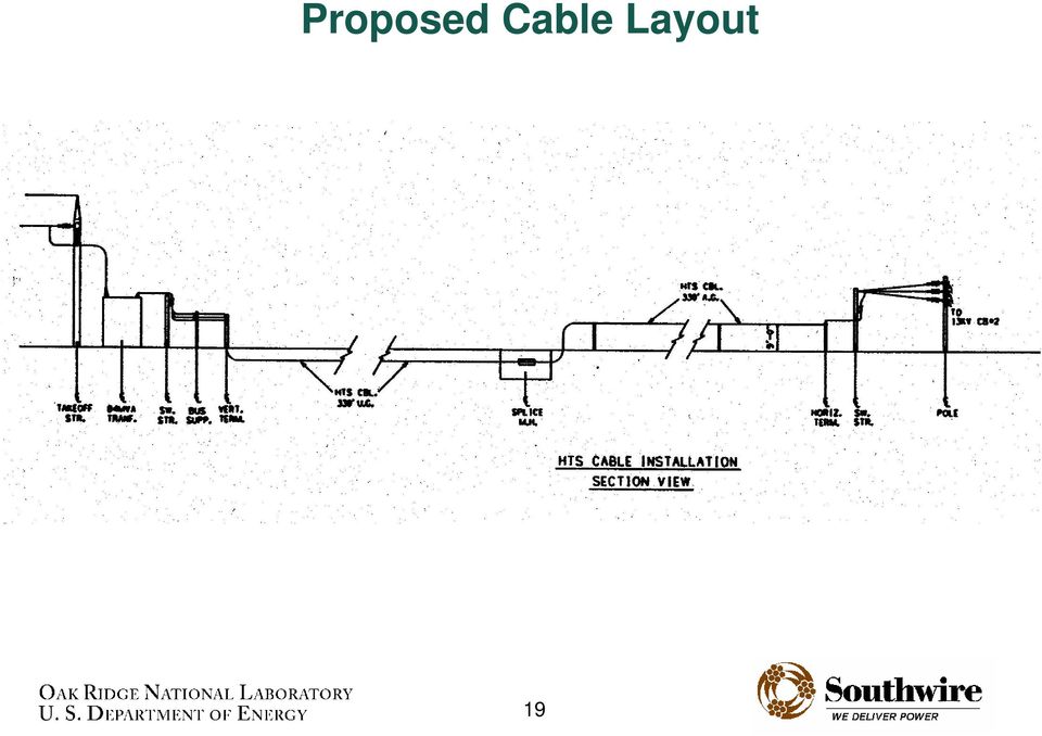
19 Proposed Cable Layout 19
20 Fault current / protection at Bixby 13.2 kv 138 kv 13.2 kv Surge arrestors to provide over-voltage protection across HTS cable SPR Inst. OC HTS Cable F Inst. OC Ω 3 20 ka-rms 56.8 ka-peak 11 3 FC: 1 st Contingency F1 5 cycles w/ no reclose F2 (bus fault) 5 cycles w/ no reclose F3 5 cycles w/ 2x auto reclose F4» 1 st trip = 5 cycles» 1 st reclose = 25 cycles» 2 nd trip = clears in 25+ cycles (depends on current level, see next page)» 2 nd reclose = 5 seconds» 3 rd trip = clears in 25+ cycles, no reclose F2 3 ~20 ka-rms ~56.8 ka-peak 3 F3 F4 10 ka-rms 28.4 ka-peak 2 nd Contingency for F1, F2, F3 is 15 cycles w/ no reclose 20
» 2 nd reclose = 5 seconds» 3 rd trip = clears in 25+ cycles, no")
21 Fault Durations on Distribution Feeders (F4) Time (sec) Distribution Feeder (F4) Fault Duration Amperes Single Phase 3 Phase Total Fault Duration. Initial fault (5 cycles) plus two reclosings (2 x plot) plus breaker time (3 cycles). Current (sec)
22 Fault currents for the AEP triaxial cable are simulated with long duration dc over current pulses Simulated 10 ka, 36 cycle (0.6 sec) fault on one distribution feeder. Current dropped to 1 ka and held for 1.5 sec note voltage immediately back to zero after fault. Indicates cable immediately recovers to superconducting state. Test simulates fault on 1 of 7 feeders leaving 13 kv bus at Bixby while nominal current is maintained on other 6 feeders during and after fault Time (sec) In 2003, 13 kv at Bixby experienced 46 outages on distribution feeders lockout after 3 faults. Current (A) Current Voltage milli Volts 22
23 Presentation Outline Introduction (David Lindsay, Southwire) Overall SPI Goals & Objectives Design Approach Review FY 2004 Milestones FY 2004 Results 30-m Cable Operation and Testing (David Lindsay, Southwire) AEP project scope & tech requirements Cable Research at ORNL (Jonathan Demko, ORNL) Cryogenic Dielectrics Research (Jonathan Demko, ORNL) FY 2004 Performance Planned FY 2005 & FY 2006 Milestones Program risk mitigation strategy Research Integration Summary 23
24 HTS Cable Research Facility has many important capabilities. Facility capability: Impulse power supply to 200 kv (BIL tests). 25,000 A pulsed dc power supply. 100 kv ac power supply 3-phase, 3000 A ac power supply. Subcooled liquid nitrogen. 24
25 The thermal conductivity of wrapped Cryoflex TM in a liquid nitrogen bath was measured. This datum is needed for design of cable cooling, particularly in the tri-axial cable design. Cryoflex TM was wrapped over a heater on a G-10 cylinder. Thermometers on either side of the Cryoflex TM provided temperature difference across a known heat load. k ( Dout Din ) ( T ) Q ln / = 2 π L T out SINDA Thermal model used to verify 1-D approximation. in 25
26 Thermal response of the triaxial cable to fault currents is under investigation Temperature (K) Regular operation End of fault After 60 sec Radius These results are for a fault on phase 1 (innermost). Measurements on instrumented short sample cables will be used to develop models. 26
27 The YBCO cable was fabricated by Southwire Co. using AMSC tape and tested at ORNL First commercial scale prototype from YBCO conductor. AMSC delivered 30-ea., 1.5-m 2G YBCO tapes. All tapes exceeded ORNL specifications 27
28 Over-current fault testing was conducted on the second generation YBCO conductor cable Commercial Grade demonstration YBCO cable (I ac > 2 ka) No degradation of I c from winding. YBCO conductor from American Superconductor Cable Specifications 1.25 m long 24 tapes Measured I c of 4200 A with an avg. n of 28 A 12 ka fault current was applied. The YBCO conductor did not degrade. New AC loss results were deferred due to damage of cable from handling. Current (A) V (mv) I = 4200 A c n = I (A) I (A) Fault over-current on 1.25-m YBCO cable Time (s) V (V) Voltage (V) 28
29 Data from a 1.5-m cable made with AMSC laminated tape will be used to compare with models. 1.5 OD stainless steel former with semicon layer. Two HTS layers, 27 tapes each layer. Nichrome heater tape installed length of cable over a kapton layer. Cryoflex TM layers wound to simulate tri-axial cable build. RTDs in center at 3 different radii. 29
30 AC losses were measured on the AMSC laminated tape cable. AC Loss (W/m) Temperature Rise (K) Current (A) Calorimetric Electrical Monoblock Power Law (n=3.8) Prototype cable with AMSC laminated BSCCO tape. Tested at ORNL. Wound 1.5-m cable with optimum lay angles. Cable had 54 tapes in 2 layers. Cable I c was ~4800+ A AC loss of the 1.5 m 60 Hz and 77 K, slope of the dashed blue curve = 3 AC loss at 3 ka rms was ~2 watt/m electrical, ~4 W/m calorimetric. The conductor temperature rise was around 1.4 K for 3 ka rms Time (minutes) 30
31 Expected fault currents were successfully withstood by the laminated cable. Current (A) Current Voltage milli Volts The upper chart is a 7 ka dc pulse for ~0.9 seconds. The voltage across the cable dropped during the pulse Current (A) Time (sec) Current Voltage Time (sec) milli Volts The lower chart is a 10 ka dc pulse for ~0.6 seconds. The current was dropped after the pulse to 1 ka for 1.5 sec. Voltage across the cable rose during the 10 ka pulse indicating that it heated up. After dropping to 1 ka the voltage indicated it was still superconducting. 31
32 Voltage-Current characteristics were unchanged after the over-current fault simulation Before After Voltage (mv) Current (A) 32
33 3.0 ka, 3-Phase Testing Triax Design Tested in pressurized liquid nitrogen, T = 79 K 1 st Proto-type: 3-Phase Triax conductor tested to 3.0 ka on all phases simultaneously. T was within limits and stable. Acceptable ac loss results 33
34 Ultera in Denmark has conducted 3-phase testing of a 3-meter triaxial cable at 3 ka Temperature rise A AC loss Calculated 3 x 3kA AC loss data 10 W/m Calibration data Radius Testing conducted in pressurized test chamber at around 2 bar. No high voltage testing was conducted. 34
35 A 5-m, 1.3 ka cable with full-scale T3-terminations was built and tested at ORNL in FY cm Connections for ac power 35
36 Difficulties in fabricating T3 lead to the T4 migration. T3 design brought out phases concentrically making a compact configuration, however: The required high thermal conductivity dielectric for T3 design failed to meet HV requirements Use of conventional dielectrics as an alternate in T3 required: Introduction of LN into the center of the termination Limited surface area in center requires addition of heat transfer enhancement Similar long dielectrics caused a major procurement problem for T2 T3 was too compact and would have to be modified to meet AEP standoff requirements T3 design utilized cast dielectric materials. 36
37 High voltage studies conducted on disk and cylindrical samples Disk samples - 1 to 15mm thick - Screened a large number of materials - Focused on Stycast FT and KT and - Araldite 5808, Filled and Unfilled Small model terminations ( Baton ) - 1-ft length cylindrical - Partial discharge versus voltage - Aging - Ramp-to-BD Large model terminations ( Barbell ) - 4-ft length - PD patterns - Breakdown strength - Dissection to locate cause of BD 37
38 Breakdown strength depends on temperature. For certain materials breakdown strength increases as the temperature decreases to LN2 Stycast 2850 KT (filled) and Araldite 5808 (unfilled) shows such improvement 38
39 Solid dielectric geometry affects performance. Pure and alumina-filled samples were tested in flat (plane-plane) and baton (cylindrical) samples PD inception voltage decreases for increasing gap and volume 39
40 Partial discharge inception voltage in Stycast 2850 KT decreases with volume. PD inception strength decreases as the stressed volume increases Samples with known defects show even lower strengths 40
41 T4 design is based on successful T2 dielectric concepts Differs from T3 in that phases are separated while cold thus eliminating the need for high thermal conductivity dielectric. Utilizes commercially available materials. Thermal conductivity is not a driving concern. 41
42 T4 termination is based on compact T2 design. PHASE CONNECTIONS 22 in Shield connection 12 in 54 in LN 42
43 Model prediction of termination temperature along vertical centerline are acceptable Temperature (K) ,000 amps 300 K ambient 3 bus bar Relative Length 43
44 Experiment set up to measure puncture and flashover strength of cylinders 44
45 Impulse breakdown of cylinders Flashover and puncture strength measured for cylinders of varying thickness Measurements made in air and in liquid nitrogen 1 bar and at high pressure 45
46 Scaling with cylinder thickness permits estimation of BIL Puncture strength (impulse voltages) decreases with thickness for cylinders Data can be used to predict minimum thickness to BIL requirements 46
47 PD inception strength measured for commercial plastic disks. PD inception measured at room temperature and in LN2 Three types of 3-mm thick disks studied (unfilled, 30% filled, 40% filled) Large statistical variation observed Modest increase in strength observed at low temperature Lower bound for PD inception: 15kV/mm 47
48 ORNL FY 2004 Performance FY 2004 Plan Continue operation of system with required PM and system management. Re-test dc-i c of cables. FY 2004 Performance Over 26,000 hours of operation Critical current measurements show robust superconductor Unattended operation (since 6/01) Complete electrical testing of the 5-m tri-axial, 3-phase, 3,000 A rms cable at ORNL. Deferred until the termination design is complete. Development of a 3 ka tri-axial termination continued. Developing dielectric materials to eliminate PD and 15 kv breakdown. 48
49 ORNL FY 2004 Performance FY 2004 Plan Complete testing of the YBCO cable (Additional ac loss and over-current tests) Complete design for cable demo at AEP Columbus and begin long lead procurements. FY 2004 Performance Measured voltage for fault currents up to 12kA. Development of a 3 ka tri-axial termination is continuing. Begin civil/electrical design & construction work at Bixby station Cable layout at site is being finalized. Ground breaking is deferred until cable system design is complete. 49
50 ORNL FY 2004 Performance FY 2004 Plan Begin construction of HTS cable for AEP. Test model cables and terminations to higher ac voltages (up to 69 kv), Requires upgraded dewar for the higher voltage levels. FY 2004 Performance Deferred until the termination design is complete. Dielectric studies have concentrated on materials for the triaxial cable terminations needed for the AEP project. Continued research improving cryogenic system performance with industry and NASA Cryostat test plan being developed that responds to issues such as pulling forces, vacuum insulation, and cable installation. 50
51 ORNL FY 2004 Additional Tasks FY 2004 Plan Tested 1- to 3-m cables to evaluate conductor architecture and minimize ac loss Participated in SPI Readiness Review FY 2004 Performance Measured thermal conductivity of Cryoflex TM on wrapped geometry. Measured copper laminated HTS tapes for ac loss and fault tolerance. Conducted design and initial testing of 3-m cable made with AMSC brass laminated HTS tapes. Mitigation plans have been prepared that address the issues identified by the Readiness Review Team. 51
52 Southwire/ORNL FY 2005 Plans Oct. 1, 2004 to Sept. 30, 2005 SPI-1: 30-m Installation, Carrollton, GA SPI contract expires 9/30/2004. Final technical report due to DOE. Disposition of system Southwire will continue operation. SPI-2: Bixby Substation, AEP, Columbus, OH 1Q,FY2005 (Oct-Dec 2004) Assemble and test full scale terminations for 3 ka 5-meter cable prototype. Fault current and bend testing of 3-meter triaxial cable. Finalize design of cryogenic system. 2Q,FY2005 (Jan-Mar 2005) Bend test of 5-meter triaxial cable. Splice test of 5-meter triaxial cable. Mechanical verification test of cryostat/cable assembly. 3Q,FY2005 (Apr-Jun 2005) Begin construction of triaxial cables for AEP project. Begin civil/electrical work at Bixby site. 4Q,FY2005 (Jul-Sept 2005) Ongoing system construction. Complete construction of triaxial cable. 1Q, FY2006 (Oct-Dec 2005) Begin on-site installation of equipment. 52
53 Risk mitigation measures: HTS Cable Risk mitigation strategy Address risks by incremental R&D steps on models and test cables: material tests on small scale samples (solid and tape dielectrics, HTS tapes, etc.) and on scaled model components (model cables and terminations for HV testing) System tests on full radial scale, short-length components (1-5 m HTS cables, full-scale terminations at ORNL). Demonstrate reliable performance for moderate periods (days) and test to IEEE requirements (ac withstand, BIL, PD, fault currents) System tests on full radial scale, moderate-length components (30-m HTS cables at Southwire). Demonstrate reliable performance for long periods (years). Periodically measure the change if any in HTS tape critical currents Multi-year utility demonstrations with cables of length 100 s of meters Design: Tough, comprehensive design reviews at the conceptual and final design points with participation from experts not working directly on the HTS cable project Conducted SPI readiness review of AEP project in February Several issues identified and are being resolved. Overcurrent fault protection Cryostat vacuum Cable Pulling Perform Failure Mode and Effects Analysis (FMEA) on key sub-systems such as terminations, cryogenics and controls 53
54 Risk mitigation measures: HTS Cable Risk mitigation strategy Assembly: Do stringent 300 K leak testing on individual components to minimize global leak rate while cold Extreme care in assembly so as not to introduce shorts or continuous current loops Cleanliness, material control to reduce out-gassing Testing: Develop test plans up-front to ensure sufficient data for successful demonstration and for relevant standards development. Proceed from lower risk to higher risk testing. Key sensors are interlocked for operator warning and then automatic actions for component protection and continuity of power. 54
55 Research Integration - Partnerships Partners with expertise and funding. Project is being conducted as a DOE SPI with equal cost sharing by Southwire and DOE. Southwire expertise includes: Wire and cable manufacturing, Established utility customer base, Design and installation of turn-key systems for utilities, Design and construction of copper rod mills world-wide, Design and construction of manufacturing plants, and now: Design, installation & operation of superconducting cables for utility customers. FY 2004 progress is evidence of well functioning team. Triax cable research conducted jointly with Southwire/nkt at ORNL. Multiple short, 1- to 3-m cables fabricated by Southwire tested at ORNL and nkt. 30-m cable operation and testing at Southwire 55
56 Research Integration - Partnerships Cold dielectric design developed by Southwire (successful 30-m demo) Warm dielectric design developed by nktc (successful 30-m demonstration in Copenhagen, Denmark) Both designs available to Ultera Ultera and ORNL exchange technical information and data regularly Teleconferences & Videoconferences Interactive web conferencing personnel exchanges site visits and technical meetings 56
57 Research Integration - Expertise and Facilities Efficient use of equipment and personnel between ORNL/Ultera. Assembly of 30-m cables has involved a team of ORNL, Southwire and subcontracted technicians. Shared use of SW ac power supply, ORNL dc power supply, SW PD detector, fault current testing to over 56 ka in Denmark. Technical capability is being established in industry by subcontracting for subsystems and components. Cryogenic system partner has been identified within U.S. industry (Praxair). Components for terminations are being manufactured by U.S. industry resulting from competitive request for quotations. Several key consultants have provided technical expertise and analysis. 57
58 Research Integration Publications and Outreach Presentations and publications during the year Four papers were presented at the Cryogenic Engineering Conference in September 2003 and were published in the, Advances in Cryogenic Engineering, Vol. 49, Four technical papers will be presented at the 2004 ASC and submitted to IEEE Transactions on Applied Superconductivity, 2005 One paper was presented at the 2003 Conference on Electrical Insulation and Dielectric Phenomena (CEIDP), in Albuquerque, New Mexico and was published in the proceedings. Web Sites ORNL Superconductivity Web Site includes Annual Reports, Peer Review presentations and other project information Southwire and Ultera Web Sites includes press releases and project information ORNL participated in HTS outreach meetings with Energetics in Pennsylvania, Ohio, and New York 58
59 As of July 1, 2004, the HTS cables have provided 100% of the customer load for over 26,000 hours 59
AMSC s Superconductor Cable Technologies for Electric Utilities
 International Workshop 2014 AMSC s Superconductor Cable Technologies for Electric Utilities Michael Ross, P.E. Managing Director of Superconductor Power Systems AMSC Corporate Facts Headquartered in MA,
HIGH-CAPACITY HIGH TEMPERATURE SUPERCONDUCTING POWER CABLES
 HIGH-CAPACITY HIGH TEMPERATURE SUPERCONDUCTING POWER CABLES Jean-Maxime SAUGRAIN NEXANS Corporate VP Technical IASS Workshop Postdam May 13, 2011 Rationale High-capacity High Temperature Superconducting
HTS Cables: Pitfalls and Potential LIPA Cable Project. J. Maguire American Superconductor. DOE Wire Workshop January, 2007 Panama City, FL
 HTS Cables: Pitfalls and Potential LIPA Cable Project J. Maguire American Superconductor DOE Wire Workshop January, 2007 Panama City, FL LIPA Project Overview Long Island Power Authority Holbrook Substation
SUPERCONDUCTING CABLE SYSTEMS
 SUPERCONDUCTING CABLE SYSTEMS INTRODUCTION An aging and inadequate power grid is widely seen as one of the greatest obstacles to the restructuring of power markets in the United States, Europe and elsewhere.
superconductors, while also working on integrating the new 2nd generation superconductors based on Y(RE)Ba 2 Cu 3 O X Ca 2
Ba 2 Cu 3 O X Ca 2") HTS Triax Energy Cable Systems HTS Cables and Accessories A New Way To Energ ize Ultera helping to create the breakthrough for HTS technology The potential of HTS technology is immense. It is not just
HTS Triax Energy Cable Systems HTS Cables and Accessories A New Way To Energ ize Ultera helping to create the breakthrough for HTS technology The potential of HTS technology is immense. It is not just
Max. Length of HTS Cables in the Future
 Max. Length of HTS Cables in the Future K. Schippl, Nexans Deutschland Industries, Hannover, Germany TOPICS: Limitation of the cable design: 1. Physical limitations 2. Shipping limitations 3. Maintenance
Development of Radiation Resistant Quadrupoles Based on High Temperature Superconductors for the Fragment Separator
 Development of Radiation Resistant Quadrupoles Based on High Temperature Superconductors for the Fragment Separator R. Gupta and M.Harrison, Brookhaven National Laboratory A. Zeller, Michigan State University
Testing and Demonstration Results of the 350m Long HTS Cable System Installed in Albany, NY
 1 Testing and Demonstration Results of the 35m Long Cable System Installed in Albany, NY C. S. Weber, SuperPower, Inc.; R. Lee, S. Ringo, The BOC Group; T. Masuda, H. Yumura, SEI and J. Moscovic, National
Development Trends of Superconducting Cable Technology for Power Transmission Applications
 , October 2-2, 205, San Francisco, USA Development Trends of Superconducting Cable Technology for Power Transmission Applications Mbunwe Muncho Josephine, Member, IAENG Abstract The use of Superconducting
Energy losses of superconducting power transmission cables in the grid
 Downloaded from orbit.dtu.dk on: Jan 28, 216 Energy losses of superconducting power transmission cables in the grid Østergaard, Jacob; Okholm, Jan; Lomholt, Karin; Tønnesen, Ole Published in: I E E E Transactions
Part 1 System Modeling & Studies for Existing Systems
 Part 1 System Modeling & Studies for Existing Systems Operation Technology, Inc. Copyright 2009 Result of rapid release of energy due to an arcing fault between two conductors. Bus voltages > 208V Temperatures
SUITABILITY OF DIFFERENT TEST VOLTAGES FOR ON-SITE TESTING OF XLPE CABLE SYSTEMS
 SUITABILITY OF DIFFERENT TEST VOLTAGES FOR ON-SITE TESTING OF XLPE CABLE SYSTEMS Michael Hensel HIGHVOLT Prüftechnik Dresden GmbH 2 3 Content 1 Introduction Test parameters and their significance Differences
High-temperature Superconducting Cable Technology and Development Trends
 ENERGY High-temperature Superconducting Cable Technology and Development Trends Takato MASUDA, Hiroyasu YUMURA, Michihiko WATANABE, Hiroshi TAKIGAWA, Yuichi ASHIBE, Chizuru SUZAWA, Takeshi KATO, Kengo
INCREASING demand for electric power coupled with lack
 IEEE TRANSACTIONS ON APPLIED SUPERCONDUCTIVITY, VOL. 15, NO. 4, DECEMBER 2005 3917 Feasibility of Electric Power Transmission by DC Superconducting Cables Pritindra Chowdhuri, Fellow, IEEE, Chandralekha
Large Current and Low AC Loss High Temperature Superconducting Power Cable Using REBCO Wires
 ENVIRONMENT and ENERGY Large Current and Low AC Loss High Temperature Superconducting Power Cable Using REBCO Wires Takashi YAMAGUCHI*, Yuki SHINGAI, Masaya KONISHI, Masayoshi OHYA, Yuichi ASHIBE and Hiroyasu
The commissioning of the LHC: first the technical systems, then the commissioning with beam
 The commissioning of the LHC: first the technical systems, then the commissioning with beam Roberto Saban 4. Ulusal Parçacık Hızlandırıcıları ve Uygulamaları Kongresi 30 Ağustos 1 Eylül 2010, Bodrum -
Lightning Arresters P30027 18 KVA P30038 10 KVA. Description & Installation
 Lightning Arresters P30027 18 KVA P30038 10 KVA Description & Installation Printed in USA 09/11 TO330 Rev. B Table of Contents Page 1.0 SCOPE 2 2.0 PRODUCT OVERVIEW 2 2.1 Intended Uses 2 2.2 Lightning
Current Limiting Protector For Systems rated 2.8-38kV and continuous currents through 5000A.
 Current Limiting Protector For Systems rated 2.8-38kV and continuous currents through 5000A. Arc Flash and Arc Blast reduction Network protection SCADA adaptable Indoor/outdoor application Professional
Trade of Electrician. Three-phase Distribution Boards And Socket Circuits
 Trade of Electrician Standards Based Apprenticeship Three-phase Distribution Boards And Socket Circuits Phase 2 Module No. 2.3 Unit No. 2.3.2 COURSE NOTES Created by Charlie Walsh - Athlone TC Revision
SF 6 Gas Insulated Switchgear Type SDF for 170 kv
 Three Phase Encapsulated Type SF 6 Gas Insulated Switchgear Type SDF for 170 kv 06B1-E-0001 With Trustworthy Technology, Structure Fuji Electric as a manufacturer of comprehensive substation equipment
EARTHING SYSTEM CALCULATION
 BAZIAN STEAL FACTORY S/S 132/11kV, 1x30/40MVA EARTHING SYSTEM CALCULATION Kurdistan Region Sulaimani May 2011 Bazian Steal Factory S/S 132/11kV, 1x30/40 MVA Contents: 1. Introduction... 3 2. List of references
Superconducting and Solid-State Electronic Fault Current Limiter Technologies The shift from demonstration projects to Business-as-Usual solutions
 Superconducting and Solid-State Electronic Fault Current Limiter Technologies The shift from demonstration projects to Business-as-Usual solutions Dr. Detlev Kirsten & Herbert Piereder Solid State SSFCL
MOBILE SYSTEM FOR DIAGNOSIS OF HIGH VOLTAGE CABLES (132KV/220KV) VLF-200 HVCD
 VLF-200 HVCD") MOBILE SYSTEM FOR DIAGNOSIS OF HIGH VOLTAGE CABLES (132KV/220KV) VLF-200 HVCD VERY LOW FREQUENCY (VLF) - PARTIAL DISCHARGES AND TANGENT DELTA HV/EHV POWER CABLES DIAGNOSTIC AND ON-SITE FIELD TESTING WITH
MOBILE SYSTEM FOR DIAGNOSIS OF HIGH VOLTAGE CABLES (132KV/220KV) VLF-200 HVCD VERY LOW FREQUENCY (VLF) - PARTIAL DISCHARGES AND TANGENT DELTA HV/EHV POWER CABLES DIAGNOSTIC AND ON-SITE FIELD TESTING WITH
High Voltage Cable Systems
 High Voltage Cable Systems Cables and Accessories up to 550 kv Completing the picture nkt cables part of a world, counting on reliable and available electrical power Today a world without electrical power
SURGE PROTECTIVE DEVICES
 SURGE PROTECTIVE DEVICES 1. INTRODUCTION In order to ensure safety of people, protection of equipment and, to a certain extent, continuity of supply, insulation co-ordination aims at reducing the likelihood
DDX 7000 & 8003. Digital Partial Discharge Detectors FEATURES APPLICATIONS
 DDX 7000 & 8003 Digital Partial Discharge Detectors The HAEFELY HIPOTRONICS DDX Digital Partial Discharge Detector offers the high accuracy and flexibility of digital technology, plus the real-time display
Fundamentals of Modern Electrical Substations Part 1: Mission of Electrical Substations and their Main Components
 Fundamentals of Modern Electrical Substations Part 1: Mission of Electrical Substations and their Main Components Course No: E02-010 Credit: 2 PDH Boris Shvartsberg, Ph.D., P.E., P.M.P. Continuing Education
Secondary Unit Substations
 14 SWITCHGEAR Secondary Unit Substations Overview Siemens offers a wide variety of unit substation designs to meet customer requirements. A unit substation consists of one or more transformers mechanically
Superconducting Cable Construction and Testing. Technical Report
 Superconducting Cable Construction and Testing Technical Report Superconducting Cable Construction and Testing 1000160 Final Report, November 2000 Cosponsor U.S. Department of Energy Forrestal Building,
Primary and Secondary Electrical Distribution Systems
 Primary and Secondary Electrical Distribution Systems Critical Facilities Round Table 12th Quarterly Membership Meeting June 2, 2006 David D. Roybal. P.E. Eaton Electrical Cutler-Hammer Products Utility
WIRE AND CABLE ENGINEERING GUIDE
 DC Hi Pot Testing Excerpt from PRYSMIAN S WIRE AND CABLE ENGINEERING GUIDE (FOR INFORMATIONAL PURPOSES ONLY) Page 1 of 6 DC HIGH POTENTIAL TESTING DC Hi-Pot testing can be applied as a withstand test (a
Selecting Current Transformers Part 1 By Darrell G. Broussard, P.E.
 By Darrell G. Broussard, P.E. Introduction: As engineers, we are aware that electrical power systems have grown. How much have they grown? When was the last time you specified a 2400-volt system, a 4160-volt
Section 5 161 kv Power Cables
 Know Your Options: 161 kv Power Cable 61 material and size material is a matter of both customer preference and required current carrying capacity Copper conductor common for larger loads When both copper
Firsts. A Year of. for US Delivery and Fabrication. December 2015. First Nuclear Grade Hardware Delivered
 December 2015 INSIDE: ITER Site Progress From the Project Manager Awards and Procurement Update Project Highlights 2015 Timeline A Year of Firsts for US Delivery and Fabrication US ITER achieved a number
HIGH VOLTAGE CALCULATIONS / EVALUATIONS. West Virginia Office of Miners Health, Safety & Training
 HIGH VOLTAGE CALCULATIONS / EVALUATIONS West Virginia Office of Miners Health, Safety & Training Helping You To Work More Safely In The Mining Industry DISCLAIMER The West Virginia Office of Miners Health,
TWENTIES WORKSHOP, EWEA 2012 Unveiling the future energy system: full scale demonstrations to reach 2020 targets. 17th April 2012
 TWENTIES WORKSHOP, EWEA 2012 Unveiling the future energy system: full scale demonstrations to reach 2020 targets 17th April 2012 Session 2 Technological challenges to cope with in TWENTIES field tests
Superconducting Power Cables. Technology Watch 2009
 Superconducting Power Cables Technology Watch 2009 1017792 Superconducting Power Cables Technology Watch 2009 1017792 Technical Update, December 2009 EPRI Project Manager S. Eckroad ELECTRIC POWER RESEARCH
ELECTRICAL ENGINEERING DESIGN CRITERIA APPENDIX F
 ELECTRICAL ENGINEERING DESIGN CRITERIA APPENDIX F TABLE OF CONTENTS Appendix F - Electrical Engineering Design Criteria F.1 Introduction...F-1 F.2 Codes and Standards...F-1 F.3 Switchyard and Transformers...F-1
KNOW YOUR OPTIONS: 69 KV XLPE POWER CABLE
 Know Your Options: 69 kv XLPE Power Cable 3 material and size material is a matter of both customer preference and required current carrying capacity Copper conductor common for larger loads When both
MECHANICAL AND THERMAL ANALYSES OF THE CABLE/ STRAND STRAIN TEST FIXTURE
 TD-01-001 January 6, 2000 MECHANICAL AND THERMAL ANALYSES OF THE CABLE/ STRAND STRAIN TEST FIXTURE Michela Fratini, Emanuela Barzi Abstract: A fixture to assess the superconducting performance of a reacted
261000 Medium Voltage Electrical Distribution
 Sections Included In This Standard: 1.1 General 1.2 Underground Cable 1.3 Medium Voltage Switches 1.4 Transformers 1.5 Electrical Manholes 1.6 Switch Vaults 1.7 Distribution Switchgear/Switchboards This
ANCILLARY EQUIPMENT AND ELECTRICAL EQUIPMENT Power Supply Systems and Electrical Equipment for Desalination Plants - Y.M. Hamud and A.H.
 POWER SUPPLY SYSTEMS AND ELECTRICAL EQUIPMENT FOR DESALINATION PLANTS Y.M. Hamud and A.H. Anwar Abu Dhabi Water and Electricity Authority, Abu Dhabi, UAE Keywords : Electrical System, Network for Desalination,
Superconducting Power Equipment. Technology Watch 2012
 Superconducting Power Equipment Technology Watch 2012 1024190 Superconducting Power Equipment Technology Watch 2012 1024190 Technical Update, December 2012 EPRI Project Manager S. Eckroad ELECTRIC POWER
Discussion on Class I & II Terminology. IEEE PES Transformers Committee Fall Meeting 2011 Boston, MA
 Discussion on Class I & II Terminology IEEE PES Transformers Committee Fall Meeting 2011 Boston, MA What is Class I & II? C57.12.00 2010 is the only document we have that defined these terms. 5.10 Insulation
World Leader in HV Testing Technology
 World Leader in HV Testing Technology Cable Fault Locators w/tdr Oil/Fluid Dielectric Testers Very Low Frequency AC Technology W/TD & PD Diagnostics Portable AC Hipots ---------------------------------
KNOW YOUR OPTIONS: 230 KV POWER CABLES
 KNOW YOUR OPTIONS: 230 KV POWER CABLES 71 CONDUCTOR MATERIAL AND SIZE Conductor material is a matter of both customer preference and required current carrying capacity At 230 kv, copper is most common
Power transformers. Generator step-up and system intertie power transformers Securing high-quality AC transmission
 Power transformers Generator step-up and system intertie power transformers Securing high-quality AC transmission Generator step-up transformers Built to withstand continuous full load Generator step-up
Electrical tests on PCB insulation materials and investigation of influence of solder fillets geometry on partial discharge
 , Firenze, Italy Electrical tests on PCB insulation materials and investigation of influence of solder fillets geometry on partial discharge A. Bulletti, L. Capineri B. Dunn ESTEC Material and Process
2a. IEM Indoor Metal Clad Medium Voltage Switchgear 15KV 16346-1. 2a. Section 16346 INDOOR METAL CLAD MEDIUM VOLTAGE SWTICHGEAR (Std.
 2a. IEM Indoor Metal Clad Medium Voltage Switchgear 15KV 16346-1 2a. Section 16346 INDOOR METAL CLAD MEDIUM VOLTAGE SWTICHGEAR (Std. Relays) Part 1 General 1.1 CONDITIONS AND REQUIREMENTS: A. Refer to
Digital Energy ITI. Instrument Transformer Basic Technical Information and Application
 g Digital Energy ITI Instrument Transformer Basic Technical Information and Application Table of Contents DEFINITIONS AND FUNCTIONS CONSTRUCTION FEATURES MAGNETIC CIRCUITS RATING AND RATIO CURRENT TRANSFORMER
Environment-Laboratory Ambient Conditions
 ISSUE 3.0: MADE MINOR CLARIFICATION CHANGES. FOR CLIENT LABS Purpose To assure laboratory conditions are stable during the performance of testing and data collection. Why this requirement is important?
How To Monitor Water Penetration In A Cable Screen
 Detection and location of high voltage cable sheath damage with Water Penetration Monitoring*) Purpose of Monitoring System The expected lifetime of high voltage underground cables is more than 40 years,
ICM Project Station Infrastructure and Equipment
 EB 0 00 Schedule B. ( pages) ICM Project Station Infrastructure and Equipment (THESL) EB 0 00 Schedule B. I EXECUTIVE SUMMARY 0. Project Description Many Municipal Substations (MS) located outside of downtown
CUSTOMER REQUIREMENTS AT POWER SUBSTATIONS
 CUSTOMER REQUIREMENTS AT POWER SUBSTATIONS Customer Handout Date Aug 2, 2010 Version 1.0 File Name Customer Requirements At Power Substations Document Id Outside Plant Engineering 1 Table Of Contents 1.0
12S, 14S, 15S Series. Time Delay Relays and Sequencers. Time Delay Relays and Sequencers. Features and Benefits. Switch Actions and Configurations
 12S, 14S, 15S Series Time Delay Relays and Sequencers Time Delay Relays and Sequencers The Therm-O-Disc type 12S, 14S and 15S series time delay relays and sequencers are field-proven devices for controlling
Single-phase (220...240 V) voltage monitoring: Undervoltage Overvoltage Window mode (overvoltage + undervoltage) Voltage fault memory selectable
 voltage monitoring: Undervoltage Overvoltage Window mode (overvoltage + undervoltage) Voltage fault memory selectable") Features 70.11 70.31 70.41 Electronic voltage monitoring relays for single and three-phase applications Multifunctional types, providing the flexibility of monitoring Undervoltage, Overvoltage, Window
Features 70.11 70.31 70.41 Electronic voltage monitoring relays for single and three-phase applications Multifunctional types, providing the flexibility of monitoring Undervoltage, Overvoltage, Window
Lessons Learned From the 1998-2004 US Pirelli-Detroit Edison Cable Demonstration
 Setup Lessons Learned From the 1998-2004 US Pirelli-Detroit Edison Cable Demonstration Paul Michael Grant EPRI Science Fellow (Retired) IBM Research Staff Member/Manager Emeritus (etc, etc...& so forth
DDX 7000 & 8003. Digital Partial Discharge Detectors FEATURES APPLICATIONS
 DDX 7000 & 8003 Digital Partial Discharge Detectors The HAEFELY HIPOTRONICS DDX Digital Partial Discharge Detector offers the high accuracy and flexibility of digital technology, plus the real-time display
A Study of a MV Cable Joint
 SERBIAN JOURNAL OF ELECTRICAL ENGINEERING Vol. 7, No. 1, May 2010, 1-11 UDK: 621.315.35:537.212 A Study of a MV Cable Joint Radiša Dimitrijević 1, Neda Pekarić-Nađ 2, Miodrag Milutinov 3 Abstract: Construction
MEDIUM AND HIGH VOLTAGE CAPACITORS, CAPACITOR BANKS AND SYSTEMS
 MEDIUM AND HIGH VOLTAGE CAPACITORS, CAPACITOR BANKS AND SYSTEMS Meher Capacitors offers reliable and innovative products and solutions in the fields of Reactive Power Compensation, Power Quality and Energy
Radial Distribution Test Feeders
 Radial Distribution Test Feeders Distribution System Analysis Subcommittee Report Abstract: Many computer programs are available for the analysis of radial distribution feeders. In 1992 a paper was published
MV, HV AND EHV SWITCHGEAR TESTING & COMMISSIONING
 Training Title MV, HV AND EHV SWITCHGEAR TESTING & COMMISSIONING Training Duration 5 days Training Date MV, HV and EHV Switchgear Testing & Commissioning 5 20 24 Apr $3,750 Dubai, UAE In any of the 5 star
Short Circuit Current Calculations
 Introduction Several sections of the National Electrical Code relate to proper overcurrent protection. Safe and reliable application of overcurrent protective devices based on these sections mandate that
CABLE DESIGN AND RELATED ISSUES IN A FAST-CYCLING SUPERCONDUCTING MAGNETS
 CABLE DESIGN AND RELATED ISSUES IN A FAST-CYCLING SUPERCONDUCTING MAGNETS A.D.Kovalenko JINR, Dubna, Russia Abstract Hollow superconducting cables for a fast-cycling synchrotrons are discussed. The essential
How To Use High Temperature Superconductor For A Power Source
 High Temperature Superconducting Current Leads for the Large Hadron Collider A.Ballarino CERN, European Organization for Nuclear Research, 1211 Geneva 23, Switzerland Abstract The Large Hadron Collider
Extend the Life of Existing Switchgear
 Extend the Life of Existing Switchgear January 2011/1910DB1002 by Hal Theobald, Product Manager Schneider Electric USA, Inc. Make the most of your energy SM Summary Introduction... p 3 Maintenance Requirements...
THE PATHWAY TO POWER HIGH-VOLTAGE CABLES
 THE PATHWAY TO POWER HIGH-VOLTAGE CABLES TABLE OF CONTENTS HIGH-VOLTAGE CABLES 3 Advantages of XLPE-insulated cable systems 3 PROPOSAL 4 Cable systems 4 Providing System Solutions 4 Continuous temperature
SECTION 16999 ELECTRICAL ACCEPTANCE TESTS
 SECTION 16999 ELECTRICAL ACCEPTANCE TESTS PART 1 2. AND 3. COMBINED 1.1 SUMMARY A. Description of Systems 1. Furnish all labor, materials, test equipment, and technical supervision to perform and record
Power transformers. Special transformers Railway
 Power transformers Special transformers Railway A leader in railway systems Our compact and low-weight transformers fully comply with the customer s specifications. The products are developed together
EVALUATION OF ON-SITE DIELECTRIC RESPONSE METHODS FOR NON- DESTRUCTIVE TESTING OF WATER TREED MV XLPE CABLES
 EVALUATION OF ON-SITE DIELECTRIC RESPONSE METHODS FOR NON- DESTRUCTIVE TESTING OF WATER TREED MV XLPE CABLES Sverre Hvidsten*, Peter Werelius**, Jørgen Christensen*** * SINTEF Energy Research (SEfAS),
3rd Generation SCR System Using Solid Ammonia Storage and Direct Gas Dosing: Expanding the SCR window for RDE
 3rd Generation SCR System Using Solid Ammonia Storage and Direct Gas Dosing: Expanding the SCR window for RDE Dr. Tue Johannessen Chief Technology Officer Amminex A/S tj@amminex.com US DoE DEER conference
Step Voltage Regulators
 Step Voltage Regulators Don Wareham Field Application Engineer Today s Agenda Introduction Voltage Regulator theory Voltage Regulator application considerations Installation and proper bypassing Wrap-up/questions
TAN δ (DELTA) CABLE TESTING OVERVIEW AND ANSWERS TO FREQUENTLY ASKED QUESTIONS. What Is Tan δ, Or Tan Delta?
 CABLE TESTING OVERVIEW AND ANSWERS TO FREQUENTLY ASKED QUESTIONS. What Is Tan δ, Or Tan Delta?") TAN δ (DELTA) CABLE TESTING OVERVIEW AND ANSWERS TO FREQUENTLY ASKED QUESTIONS What Is Tan δ, Or Tan Delta? Tan Delta, also called Loss Angle or Dissipation Factor testing, is a diagnostic method of testing
TAN δ (DELTA) CABLE TESTING OVERVIEW AND ANSWERS TO FREQUENTLY ASKED QUESTIONS What Is Tan δ, Or Tan Delta? Tan Delta, also called Loss Angle or Dissipation Factor testing, is a diagnostic method of testing
Technical Specification for the Cryogenic Testing of HTS Current Leads
 Group Ref.: AT-MEL-CF EDMS No.: 44036 The Large Hadron Collider Project IT-3303/AT/LHC Technical Specification for the Cryogenic Testing of HTS Current Leads Abstract This specification concerns the testing
1ZSE 2750-105 en, Rev. 8. Transformer bushings, type GOE and GOE(2) Technical guide
 Technical guide") 1ZSE 2750-105 en, Rev. 8 Transformer bushings, type GOE and GOE(2) Technical guide Original instruction The information provided in this document is intended to be general and does not cover all possible
1ZSE 2750-105 en, Rev. 8 Transformer bushings, type GOE and GOE(2) Technical guide Original instruction The information provided in this document is intended to be general and does not cover all possible
MiCAFIL. 1 RIP Technology. Bushings. Z. Zic 09/2003
 MiCAFIL 1 RIP Technology Z. Zic 09/2003 )XQFWLRQRI+LJK9ROWDJH%XVKLQJ Uncontrolled (natural) electrical field Capacity-controlled electrical field %XVKLQJV0DLQ,QVXODWLRQ6\VWHPV 7\SH 0DLQ,QVXODWLRQ +RXVLQJFRYHU
Brookhaven Magnet Division - Nuclear Physics Program Support Activities
 Brookhaven - Nuclear Physics Program Support Activities Spin Program support E-Cooling R&D RIA RHIC Operations Support Funding AGS Warm Siberian Snake AGS Warm Snake Magnetic element designed and built
Motor Protection Voltage Unbalance and Single-Phasing
 Motor Protection Voltage Unbalance and Single-Phasing Cooper Bussmann contributes the following information, which is an excerpt from their 190-page handbook SPD Selecting Protective Devices Based on the
Bulletin 150 Smart Motor Controllers SMC-3 Smart Motor Controller
 Overview/Modes of Operation Bulletin 150 Smart Motor Controller The SMC-3 is a compact, simple to use, solid-state motor controller designed to operate 3-phase motors. It features a built-in overload relay
3.1.1 Full Type Tests & Routine Tests according to Clause 8 2 & 8 3. 4.0 Instructions For Installation, Operation & Maintenance
 SPECIFICATION FOR LOW VOLTAGE SWITCHBOARD SEN I N D E X Description 10 STANDARD TECHNICAL REQUIREMENTS 11 Standards 12 General Operating Conditions 13 General Description Of Switchboard 131 Structure 132
How To Test For Safety On A Power Cable
 T H E M A G A Z I N E O F 7 x 2 4 E X C H A N G E I N T E R N AT I O N A L A Green Approach to Building a Superior Data Center S P R I N G 0 9 BUILD FOR TODAY. EXPAND ON DEMAND. Modularity in the data
POWER AND VOLTAGE RATING
 POWER AND VOLTAGE RATING SCOPE: The purpose of this document is to take the confusion out of power and voltage ratings in specifications and in product information publications. This will be accomplished
Comparative study for cables and busbars
 Comparative study for cables and busbars Preliminary considerations To compare the prices of two categories of product as different as traditional cables and busbars, it is necessary to make some preliminary
STAR PIPE Polska S.A ul. Gdyńska 51 62-004 Czerwonak tel. +48 61 667 41 20 fax +48 61 667 41 38
 THE ALARM SYSTEM The base of the system consists of two non-insulated copper alarm wires with section equal to 1.5 mm2, located inside polyurethane foam parallel to the conduit pipe, offset in relation
EFFICIENT ELECTRICAL ENERGY TRANSMISSION AND DISTRIBUTION INTERNATIONAL ELECTROTECHNICAL COMMISSION
 EFFICIENT ELECTRICAL ENERGY TRANSMISSION AND DISTRIBUTION INTERNATIONAL ELECTROTECHNICAL COMMISSION EFFICIENT ELECTRICAL ENERGY TRANSMISSION AND DISTRIBUTION 1 EFFICIENT ELECTRICAL ENERGY TRANSMISSION
Submit shop drawings for equipment provided under this section Shop drawings shall indicate:
 Section 16435 - SWITCHBOARDS Introduction Part 1 - General Reference The work under this section is subject to requirements of the Contract Documents including the General Conditions, Supplementary Conditions,
METAL-CLAD AND METAL-ENCLOSED SWITCHGEAR 3.6KV~40.5KV. tgood.com. Energy. Fast.
 METAL-CLAD AND METAL-ENCLOSED SWITCHGEAR 3.6KV~40.5KV tgood.com Energy. Fast. TGOOD produces over 5000 switchgear units annually for projects around the globe PRODUCT OVERVIEW Integral substation component
A. 5MWp SPV Plant at Khimsar, Rajasthan. B. 5MWp SPV Plant Installed Technologies. D. 5MWp SPV Plant Challenges. E. 5MWp SPV Plant - Performance
 An overview & Performance Analysis of 5 MWp Solar PV Plant at Khimsar, Rj Rajasthan Reliance Industries Limited June 2, 2011 July 2010 Contents A. 5MWp SPV Plant at Khimsar, Rajasthan B. 5MWp SPV Plant
Transformer Bushings for GIS
 Transformer Bushings for GIS Oil to SF6 Connections GARIP RTKG 725-55 kv SQS certified ISO 91 / ISO 141 Bushings RIP - Technology for SF6 / Oil - Bushings In modern metal enclosed switchgear SF6 -gas is
Cable Selection for Medium Voltage Capacitor Banks and Harmonic Filter Banks
 Cable Selection for Medium Voltage Capacitor Banks and Harmonic Filter Banks Introduction This document presents the fundamental aspects of cable and conductor selection for connecting pad mounted shunt
ESB Networks Response. ERGEG Consultation. Voltage Quality Regulation in Europe
 NETWORKS ESB Networks Response to ERGEG Consultation on Voltage Quality Regulation in Europe Date: 22 February 2007 Distribution System Operator ESB Networks Page 1 of 12 Contents 1.0 INTRODUCTION...3
F05D Meeting on Damped AC Voltage Testing
 October 28 th, 2008 from 03.30-5.30 pm in San Antonio, TX Agenda F05D Damped AC Voltage Testing 1 Agenda F05D Damped AC Voltage Testing Welcome: Introduction On-site testing voltages e.g. IEC 60060-3 High
the quality par excellence Meghna Industries Manufacturer of : All types of fiberglass Cables
 the quality par excellence Meghna Industries Manufacturer of : All types of fiberglass Cables ABOUT US Since our beginning in 1995, We - MEGHNA INDUSTRIES have been one of the fastest growing manufacturer
L.I. Chubraeva. Corr. Member of RAS
 STATE-OF OF-THE-ART AND NEW DEVELOPMENTS IN HIGH-TEMPERATURE CUPERCONDUCTIVITY IN RUSSIA L.I. Chubraeva Corr. Member of RAS Director of Research Institute of Innovative Technologies in Electromechanics
IEEE POWER ENGINEERING SOCIETY CHICAGO CHAPTER THE OKONITE COMPANY WEDNESDAY JANUARY 11, 2006 JIM FITZGERALD ENGINEERING LINGO
 IEEE POWER ENGINEERING SOCIETY CHICAGO CHAPTER THE OKONITE COMPANY WEDNESDAY JANUARY 11, 2006 JIM FITZGERALD ENGINEERING LINGO WHEN YOU HEAR AN ENGINEER SAY A NUMBER OF DIFFERENT APPROACHES ARE BEING IMPLEMENTED
UGVCL/SP/591/11KV HT AB CABLE
 TECHNICAL SPECIFICATION FOR 11KV AERIAL BUNCHED CABLES FOR OVERHEAD LINES (CROSSED LINKED POLYTHENE DRY GAS CURED) 1. SCOPE This specification covers requirements of XLPE insulated, 11 KV Aerial Bunched
SnoTrace KSR Surface Snow and Ice Melting INSTALLATION PROCEDURES
 SnoTrace Surface Snow and Ice Melting INSTALLATION PROCEDURES SnoTrace INSTALLATION PROCEDURES Refer to the SnoTrace Cable Testing Report for required recording of test data and circuit information. Upon
SM6 Series Circuit Breaker Monitors CONSOLIDATED. Electronics, Inc. MONITORING THE FUTURE
 Series Circuit Breaker Monitors CONSOLIDATED Electronics, Inc. MONITORING THE FUTURE Why SF Gas Density Monitors? 6 Cut Maintenance Costs Your capital investment may be recovered with the elimination of
Ampacity simulation of a high voltage cable to connecting off shore wind farms
 Ampacity simulation of a high voltage cable to connecting off shore wind farms Eva Pelster 1, Dr. David Wenger 1 1 Wenger Engineering GmbH, Einsteinstr. 55, 89077 Ulm, mail@wenger-engineering.com Abstract:
Electric Heat Tracing INSTALLATION PROCEDURES
 INSTALLATION PROCEDURES The following installation procedures are suggested guidelines for the installation of a Thermon electric heat tracing system 1. Individuals installing these products are responsible