TABLE OF CONTENTS DETAILED SPECIFICATIONS SANITARY SEWER
|
|
|
- Adelia Thornton
- 8 years ago
- Views:
Transcription
1 TABLE OF CONTENTS DETAILED SPECIFICATIONS SANITARY SEWER SECTION I GENERAL...1 SECTION II PAYMENTS...1 SECTION III - GENERAL REQUIREMENTS FOR ALL SEWER PIPE INSPECTION...1 SECTION IV - SEWER PIPE MATERIALS...2 SECTION V - LATERAL CONNECTIONS...3 SECTION VI MANHOLES...4 SECTION VII - LAYING SEWER PIPE...7 SECTION VIII - WIDTH OF TRENCH FOR PIPE SEWERS...9 SECTION IX - DRAINAGE OF EXCAVATION...9 SECTION X - PIPES CROSSING TRENCH...9 SECTION XI - LOWER SANITARY HOUSE SEWERS...10 SECTION XII TELEVISING SANITARY SEWERS...10 SECTION XIII - LEAKAGE TESTING OF SANITARY SEWERS...10

2 DETAIL SPECIFICATIONS SANITARY SEWERS SECTION I GENERAL All work shall be done in accordance with relevant sections of the following documents: a. Kenosha Water Utility Standards and Specifications b. Wisconsin Administrative Code c. Standard Specifications for Sewer & Water Construction in Wisconsin, latest Edition d. DNR Chapter 110, Sewerage Systems e. Wisconsin Construction Site Best Management Practice Handbook, DNR SECTION II - PAYMENTS Payments when applicable will be based on measurements of the sewer line from center to center of manholes, when pipe actually goes through the manhole, or a flow line is formed through the manhole. All stubs out of a manhole shall be paid for as actual length of pipe. Manholes shall be measured by the vertical foot from the invert to the bottom of the frame, including adjusting rings. Building laterals connected to wyes shall be measured from the end of the wye to the right of way line. Risers shall be paid based on the vertical length of pipe used. Building laterals connected to risers shall be measured from the end of the riser to the right of way line. SECTION III - GENERAL REQUIREMENTS FOR ALL SEWER PIPE INSPECTION A. Inspection The quality of all material, the process of manufacture and the finished pipe shall be subject to inspection and approval by the Engineer. Each length of pipe shall be subject to inspection at the factory, point of delivery, and site of the work. The purpose of this inspection shall be to detect faulty materials or methods used in the manufacture of pipe and to cull and reject pipe which, independent of physical tests specified, fail to conform to the requirements. The testing laboratory will select and mark the proper number of pipe of each size to be tested, using such systematic method of selection as will guarantee that the specimens selected shall be truly representative of the whole shipment. B. Method And Number Of Physical Tests Physical tests will be made according to the methods described in the latest standard specifications of the American Society for Testing and Materials, including the following detailed requirements which shall govern where they alter the ASTM Standards: For all sewer pipe, one percent (1%) of the number of pipe to be laid in each size shall be tested. Tests conducted by an approved testing agency shall be performed to determine: pipe dimensions, (including the average outside and inside diameter and the minimum and average wall thickness), pipe stiffness at 5% deflection, pipe flattening deflect the pipe to 60% deflection and remove the load and examine the specimen for evidence of splitting, cracking, breaking. A minimum number of two specimens to be tested for each size. All materials delivered to the site and incorporated into the work shall be accompanied by proper testing documentation. The cost of all testing shall be by the supplier. C. Acceptance Or Rejection All specimens delivered to the site shall be accompanied by testing documentation. Materials not accompanied by testing documentation shall be subject to rejection until adequate assurance is received Detailed Specifications Sanitary Sewers Page 1 Revised August 2007

3 that the materials meet specifications through additional testing. In the event that any of the test specimens fail to meet the requirements, all pipe represented by such tests shall be subject to rejection. D. Rejection Pipe shall be subject to rejection on account of any of the following visual deficiencies: 1. Fractures or cracks passing through the pipe wall or socket, except that a single crack not exceeding 2 inches in length at either end of the pipe or a single fracture in the socket not exceeding 3 inches in width nor 2 inches in length shall not be considered cause for rejection unless these defects exist in more than 5% of the entire shipment or delivery. 2. Chips or fractures on the interior of the pipe exceeding 2 inches in length, 1 inch in width, and of a depth more than one-fourth (1/4) of the barrel thickness. 3. Cracks, sufficient to impair the strength, durability or serviceability of the pipe. 4. Defects that indicate improper proportioning, mixing, and molding. 5. Variations of more than 1/8 inch per linear foot in alignment of a pipe intended to be straight. 6. Insecure attachment of spurs or branches. 7. Damaged ends, where such damage would prevent making a satisfactory joint. 8. Extensive patching or painting of any surface of pipe. 9. Variations in any dimension exceeding the permissible variations given in Table 19, section of the Standard Specifications for Sewer & Water Construction in Wisconsin. SECTION IV - SEWER PIPE MATERIALS A. Sanitary Sewer Main Sanitary sewer main shall be generally located at the centerline of the proposed street. The minimum size for sanitary sewer main is 8. Sanitary sewer main shall be installed using Polyvinyl Chloride Pipe (PVC) and shall be of class SDR 26 for depths up to 25' deep. PVC pipe & Fittings -- 8 inch thru 15 inch shall meet ASTM Standards D3034 and F-789/PS inch thru forty eight inch shall meet ASTM Standards F-679 or F-794. For depths greater than 25', pipe shall be PVC class C-900 or 905, ductile iron, or concrete and designs shall be approved separately by the Engineer. Pipe shall be marked at intervals of 5 feet or less as follows: 1. Manufacturer's name or trademark. 2. Nominal pipe size. 3. PVC cell classification. 4. The legend, i.e. Type PSM SDR 26 PVC Sewer Pipe 5. ASTM Designation D3034 or F Extrusion date, period of manufacture, or lot number. B. Sanitary Force Main Sanitary force mains shall be PVC water main class pipe conforming to AWWA C-900 or 905 with a pressure class not less than 150, and a dimension ratio not greater than DR 18. A #12 gage standard solid green PVC coated copper tracer wire shall be used along the top of the pipe, taped at 10' intervals. Tracer wire shall be brought to grade in polyiron valve boxes by Armor located every 300' along the route. The valve box cover shall be labeled Sewer and shall extend from the force main to finished grade. Pipe shall be marked at intervals of 5 feet or less as follows: 1. Manufacturer's name or trademark. Detailed Specifications Sanitary Sewers Page 2 Revised August 2007

4 2. Nominal pipe size. 3. Type of plastic pipe material. 4. SDR number. 5. AWWA or ASTM designation. 6. Laboratory marking the evaluation of the pipe. C. Joints PVC pipe shall have elastomeric gasket joints, providing a water tight seal. The assembly of joints shall be in accordance with the pipe manufacturer's recommendations. Joint shall be approved by the Engineer and conform to the requirements of ASTM Designation F-477, latest revision. The assembled joint shall pass the performance tests required in ASTM D D. Fittings Sanitary Sewer Main Fittings such as saddles, tees, wyes, elbows and others on gravity sanitary sewer shall be of PVC pipe material corresponding to and having a joint design compatible with adjacent pipe. Approved adapters shall be provided for transition to other types of pipe. Fittings shall be clearly marked as follows: 1. Manufacturer's name or trademark. 2. Nominal size. 3. Material designation. 4. ASTM designation D-3034 or F-679. E. Fittings Sanitary Force Main Fittings on sanitary force mains shall be ductile iron, class 250 conforming to AWWA C-110/ANSI A21.10 or cast ductile iron compact fittings conforming to AWWA C-153/ANSI A with a pressure rating of 350. Fittings shall have a cement mortar lining and an internal bituminous coat conforming to AWWA C-104/ANSI A21.4. All fittings shall have mechanical joints using Megalugs with rubber gaskets and Cor-blue fluorocarbon coated T-bolts and nuts. All ductile iron fittings shall be wrapped with polyethylene encasement in accordance with AWWA C-105/ANSI A Fittings shall be clearly marked as follows: 1. Manufacturer's name or trademark. 2. Nominal size. 3. Material designation. 4. ASTM designation D-3034 or F-679. SECTION V - LATERAL CONNECTIONS A. Code All building sewer services from the main to the right of way (ROW) shall be installed in accordance with Chapter 32, Rule 7 of the KWU Rules and Regulations and the local plumbing code and regulations. All building sewer services beyond the ROW shall be installed in accordance with the Department of Commerce Chapters 82 to 87 Plumbing and the local plumbing code and regulations. B. Design Standards The minimum lateral diameter from the main to the right of way line shall be 6. Pipe material shall be PVC SDR-26 conforming to ASTM D-3034 or F-789/PS46, with rubber gasket joints conforming to ASTM F-477. Sewer laterals will in general be laid to a grade of 1/4 inch to the foot. Detailed Specifications Sanitary Sewers Page 3 Revised August 2007

5 The top of the sewer stub at the curb line shall be a minimum of 9 feet and a maximum of 10 feet below grade at the property line. Risers 6 inches in diameter shall be installed on all sewers over 10 feet in depth. Risers shall be used to bring the sanitary sewer to a minimum depth of 9 feet and a maximum depth of 10 feet. Risers shall be encased in an envelope of compacted bedding material, refer to the detail sheet. If 3/4 crushed stone chips or sand is used as cover and backfill material, no compaction is needed. Any deviation over 2 feet from the wye location on the plans shall require prior approval of the Engineer. C. Wye Connection When installing mainline sanitary, a prefabricated wye fitting shall be installed for each lateral connection. When installing sanitary laterals to existing mainline sanitary, a "cut-in-wye" shall be used and installed by core drilling a hole in the main and attaching a flexible rubber T or Y saddle with stainless steel clamps. Another acceptable fitting is an Inserta-Tee, installed according to the manufacturer's recommendations. D. Manhole Connection Sanitary sewer laterals will be connected to the mainline and not connected to manholes, whenever possible. Building sanitary sewers shall not be connected to a manhole at an elevation of more than 24 inches above the springline of the outgoing sewer. Where the difference in elevations are greater than 24 inches, the connection shall be made with an outside drop connection. E. Lateral Stubs Unused stubs shall terminate with the last pipe being 2 feet long, and shall be plugged using a Cookie compatible joint. A 2" x 4" stake, 4 feet long (or equal) and painted green shall be placed vertically at the end of all laterals or wyes to locate the termination for future extensions. F. Tracer Wire A #12 AWG THWN solid copper tracer wire with green colored insulation shall be installed with the service pipe. The wire shall be centered over the top of the pipe and shall extend from the building foundation to the main. If the sanitary sewer lateral is in the same trench as the water service, the tracer wire shall be brought to grade in the water curb box. If the sanitary sewer lateral is in a separate trench, a second curb box with a lid labeled sewer shall be placed at the building exterior and the tracer wire shall be brought to grade inside of the curb box. SECTION VI - MANHOLES A. Design Standards Manholes shall be located at any bend or deflection locations when laying sanitary sewer. Spacing of manholes shall be at a maximum of 400 feet in accordance with NR for sewers of 15 inches or less. Manhole barrels shall be constructed of pre-cast reinforced concrete sections. The minimum diameter of manholes shall be 48 inches for pipe that is 8 to 24 in diameter. Refer to the table on the detail sheet. Pre-cast manholes and tops shall conform with ASTM Specifications, C478, latest revision. Pre-cast manholes are to be provided with eccentric cones. The minimum wall thickness shall be in conformance with the table on the detail sheet. Reinforced integral floors shall have a minimum thickness of 6 inches. The top of the pre-cast cone shall have minimum 3 vertical ring integrally cast with the cone. The surface shall be smooth and free of form offsets cracks or excessive honeycomb. Detailed Specifications Sanitary Sewers Page 4 Revised August 2007

6 Each pre-cast reinforced concrete manhole riser and top section shall be clearly marked with the name or trademark of the manufacturer and the date of manufacture. This marking shall be indented into the manhole section or shall be painted thereon with waterproof paint. B. Testing Pre-cast reinforced concrete manhole risers and tops shall be tested in accordance with ASTM Designation C-497 by a testing laboratory, approved by the Engineer, for concrete compressive strength compliance by compression tests on cores drilled from 5% of the lot. When manhole sections are made on a sewer pipe machine, the number of compression tests on cores may be reduced to one percent of the lot, with a minimum of two cores per lot. Unless otherwise specified, absorption tests will be waived. Each manufacturer shall provide a suitable core-drilling machine conforming to ASTM Designation C-497 on his premises and an operator to take test cores as directed by the Testing Laboratory personnel. All sampling, monogramming and testing expenses incurred by the testing laboratory shall be paid by the Owner and back-charged to the Contractor through deductive billing. Pre-cast reinforced concrete manhole risers and tops meeting the strength requirements will be considered acceptable and shall be stamped with an appropriate monogram. Special bottom risers and adjusting rings need not be tested. Copies of test reports shall be submitted to the Engineer before the manhole sections are installed in the project. Final acceptance will be made after field inspection upon delivery to the job site. C. Rejection Pre-cast reinforced concrete manhole risers and tops shall be subject to rejection for failure to conform to any of the testing specification requirements. In addition, individual sections of manhole risers and tops may be rejected because of any of the following reasons: 1. Fracture or cracks passing through the wall, except for a single end crack that does not exceed the depth of the joint. 2. Defects that indicate imperfect proportioning, mixing and molding. 3. Surface defects indicating honey-combed or open texture. 4. Damaged ends, where such damage would prevent making a satisfactory joint. 5. Manhole steps out of line, or not properly spaced. 6. Visible infiltration into manhole. 7. The internal diameter of the manhole section shall not vary more than one percent from the nominal diameter. 8. Any continuous crack having a surface width of 0.01 inch or more and extending for a length of 12 inches or more regardless of position in the section wall. D. Height Adjustment All adjustments of manhole height from the top of cone shall be made with pre-cast rings meeting the requirements of MATERIALS FOR ADJUSTMENT OF MANHOLES AND INLETS in Section XXIX of the GENERAL SPECIFICATIONS. Pre-cast concrete rings shall have an inside diameter to match the manhole opening, be not less than 2 inches nor more than 6 inches high, and have a wall thickness of 6 inches unless otherwise specified. The rings shall contain a minimum of one No. 2 reinforcing rod centered within the ring. Where necessary rings shall be grooved to receive manhole steps. No cracked or broken rings shall be used. Detailed Specifications Sanitary Sewers Page 5 Revised August 2007

7 The top of pre-cast manhole cones shall be set a maximum of 18 inches lower than established grade in unimproved areas, with the top of the manhole cover being ringed up flush with the existing ground. The maximum number of adjusting rings to be used in unpaved areas shall be nine 2 rings or a total of 18. The minimum number of adjusting rings shall be one 2 ring. The maximum height of adjusting rings shall be 8 in paved areas. All joints between the adjusting rings shall be filled with grout or mortar, including between the cone and the adjusting ring and the adjusting ring and the frame. In new subdivisions, the cone section will be set to 8 inches below finished grade, a steel plate will be placed over the cone section and the pavement will be placed to the binder grade. The asphalt will be sawcut and removed around the manhole and the casting will be set to binder grade. The chimney seal will be installed at this time. When the final lift of asphalt is placed a paving ring will be installed in the casting frame to bring the lid to finished grade. No laterals shall be extended or connected to until after manhole castings are set to binder grade or finish grade. E. Joints Joints for pre-cast manholes shall meet the requirements of ASTM C-443, latest revision, except that sealant shall be butyl rubber gasket or butyl rubber rope. Flexible butyl rubber gaskets or rope shall comply with the physical requirements for Type B gaskets in AASHTO Designation M-198, or Federal Specification SSS A, sealing compound, preformed plastic for expansion joints and pipe joints. F. Pipe Connection to Manhole All sanitary sewer pipe to manhole connections shall be with a flexible, watertight pipe to manhole seal meeting the requirements of ASTM C-425 and C-443. All new manholes will have factory installed boots built into the structure, prior to delivery to the job-site. Kor-N-Seal boots by NPC or approved equal shall be used. G. Steps All manholes shall be provided with steps equally spaced vertically at 16 inches on center installed by the manufacturer. Steps shall be embedded into the riser or conical top section of the wall a minimum of 3 inches. Manhole steps shall be Neenah R 1980-C or equal made of gray cast iron conforming to the requirements of ASTM Designation A-48 Class No. 30B and shall have a minimum cross sectional dimension of one inch in any direction. Each section of the manhole shall be aligned so the steps create a continuous ladder. H. Frame and Lid All sanitary manholes shall be installed with a casting with self-sealing lid ground and machined bearing. Cover shall have two concealed pick holes which allow no water to enter the manhole and shall be embossed or engraved with Kenosha Water Utility, refer to the Detail Sheet. Neenah R-1642 or EJIW All manholes shall have an internal chimney/external chimney seal by Adaptor Inc. or approved equal, installed after final grade is established. The chimney seal shall extend from the top of the cone section to the base of the frame. Seal materials shall conform to ASTM C-877 or ASTM C-923. Any metal parts shall be made of Type 304 stainless steel. I. Sealing Manholes All sanitary manholes shall have an exterior joint sealer applied to each joint, meeting the requirements of ASTM C-877. Acceptable manufacturer shall be MacWrap External Collar by Mar Mac Construction Products Co. Inc. or EZ-wrap by Press Seal Gasket Corporation. The sealer installation shall be approved by the Engineer after application and prior to backfilling. If a manhole is leaking prior to final acceptance by the Utility, manholes shall have all internal barrel Detailed Specifications Sanitary Sewers Page 6 Revised August 2007

8 joints grouted and an epoxy coating may be required. No cementitious lining will be allowed. J. Construction Requirements All manholes are to be constructed as detailed on the Standard Detail Sheet. The flow lines shall be continuous through the manhole and in cases where the pipe is not extended through, provide a smooth channel by pouring concrete (Class "A") up to the spring line of the pipe. A pre-cast manhole bottom section may be used for Type "B" manholes. Manholes will be brought to proper grade as the job progresses, and within forty-eight (48) hours after the pipe has been installed at the stations requiring a manhole, the base will be poured and the top half of that portion of the pipe within the manhole shall be broken away and neatly trimmed flush with the top of the shoulder. The pipe shall be cut flush with the contour of the inside wall. When a sewer main or lateral enters a manhole any distance above the manhole invert, bedding material shall be placed the full depth of the excavation under the pipe prior to laying of pipe. Any sewer main or lateral entering a manhole greater than 2' above the flowline shall be an outside drop manhole, Type D or DD. The drop pipe shall be the same diameter as the incoming sewer. K. Sampling Manhole A sampling manhole will be required on all sanitary sewer laterals extending from businesses with food service facilities or possible future food service facilities, or from industrial buildings with manufactured by-products or as required by the General Manager. SECTION VII - LAYING SEWER PIPE A. Line and Grade The grade of sewer pipe as shown on the profile is that of the inner side of the invert and to which the work must conform. A variation of 1/2 inch from either line or grade will be deemed sufficient reason to cause the work to be rejected and rebuilt. All pipes shall be laid with bells uphill and work will progress upgrade. The contractor shall use the laser beam method of maintaining line and grade. Prior to approval, the Contractor shall submit evidence to the engineer that a qualified operator will handle the laser beam equipment during the course of construction. When the laser beam is used, batter boards will be required to be installed the first 50 feet of pipe, and the contractor shall check the line and grade at any additional points at which offset stakes have been placed whenever so requested by the Engineer. If bending of the beam due to air temperature variations becomes apparent with "in the pipe" units, a fan shall be provided to circulate the air. However, air velocity shall not be so excessive as to cause pulsating or vibrating of the beam. If, in the opinion of the Engineer the beam cannot be accurately controlled, this method of setting line and grade shall be abandoned. B. Bedding, Cover, & Backfill The bottom of the trench shall be undercut to provide a minimum of 4" inches of bedding material between the natural soil and the bottom outside barrel of the pipe to be installed. The bedding material will be tamped and bell holes excavated prior to the installation of the pipe. The pipe is to be entirely surrounded and covered to a height of at least 1 foot above the top with granular backfill material. Granular material shall be carefully placed by hand to fill completely all spaces under and adjacent to the Detailed Specifications Sanitary Sewers Page 7 Revised August 2007
 hours after the pipe has been installed at the stations requiring a manhole, the base will be poured and")
9 pipe, and hand tamped in layers not exceeding 6 inches in thickness. In lieu of hand tamping the granular backfill, approved bedding stone may be placed to 1 foot over the pipe without compaction. All pipe laid in open-cut trench shall have a minimum clearance of 6 inches between outside wall of pipe barrel and face of sheathing. Refer to the detail sheet. In backfilling, the pipes must not be disturbed from line or grade. Material used for bedding, cover, and backfilling will conform to the specification Section XXIV in the General Specifications. All granular backfill shall be compacted to a minimum density of 95% of Standard Proctor Density. Refer to Section XXVII of the General Specifications. The contractor will be held liable for pipe breakage and misalignment caused during backfilling. C. Open Trench Not more than 400 feet of trench shall be open in advance of the completed sewer including backfill, manholes, and cleanup, without the written permission of the Engineer. Lateral trenches will not be left open for more than forty-eight (48) hours. All trenches left open overnight shall be properly fenced and barricaded. D. Keeping Pipe Clean The interior of the sewer shall, as the work progresses, be cleared of all dirt, cement and superfluous materials of every description. The end of all pipe will be plugged with a water tight plug, approved by the Engineer, except during working hours while additional pipe is being added to those places. The new sanitary sewer shall have a mechanical plug installed at the connection to the existing sanitary sewer, which is to stay in place until the new sanitary sewer is accepted. The plug will be removed upon satisfactory final inspection. E. Connecting Different Pipe Materials When a new sewer is to be laid starting from an existing sewer with a different type of joint, or in relaying or reconnecting building sewers, the connecting joint shall be made with a flexible rubber coupling by Mission or Fernco or approved equal. The coupling shall be securely strapped to the pipe with a stainless steel strap on each side of the joint. If required by the Engineer, it shall be encased in concrete a minimum of 6 inches thickness around the entire repair coupling and for a distance of at least 12 inches on each side of the joint. F. Cold Weather When laying sewer pipe in cold weather, the Engineer may stop the work when the quality of work is in danger. Rubber gaskets or joint material shall be warmed to ensure a proper seal. No pipe shall be laid on frozen ground. G. Minimum Slopes Minimum slopes for mains shall be according to NR Table 1, as follows: 8-inch 0.40 (ft/100 ft) 10-inch 0.28 (ft/100 ft) 12-inch 0.22 (ft/100 ft) 15-inch 0.15 (ft/100 ft) 18-inch 0.12 (ft/100 ft) 21-inch 0.10 (ft/100 ft) 24-inch 0.08 (ft/100 ft) H. Deflection Test Deflection tests shall be performed by the Contractor and witnessed by the Engineer for all sewer pipe Detailed Specifications Sanitary Sewers Page 8 Revised August 2007

10 installed. The deflection test shall be performed using a rigid ball or mandrel, and shall be performed without mechanical pulling devices. The test shall be performed after all backfill has been placed and consolidated but before paving is completed. If deflection testing occurs within 30 days of placement of the final backfill, deflection may not exceed 5%. This test is performed by using the 95% testing device. Maximum deflection may not exceed 7.5% when testing occurs more than 30 days after placement of the final backfill. This test is performed by using the 92.5% testing device. The dimensions of the devices are listed in Table 1, Section 3.2.6(i)4, of the Standard Specifications for Sewer & Water Construction in Wisconsin. SECTION VIII - WIDTH OF TRENCH FOR PIPE SEWERS The maximum width of the trench excavation at the top of the pipe shall be the outside diameter of the pipe used plus 24 inches, except when close sheathing is required. In case of deep trenches requiring the use of additional sets of stringers and sheathing, the width of trench may be increased to allow for the additional stringers and sheathing, provided the lower set is held to the minimum width required to lay the pipe. Where the trench width for that portion of trench depth between the trench bottom and the outside top of the pipe barrel, for any reason exceeds the width provided for the class of pipe shown on the sewer plan profile for the bid section, the Contractor shall furnish a stronger class of pipe for that section adequate for the actual trench width, for no additional compensation. When laying flexible pipe, if for any reason the trench width exceeds that allowed, a concrete cap, envelope or trench restoration shall not be used. Instead, the bedding and cover material shall be extended at least 2.5 pipe diameters from either side of the pipe or to the undisturbed trench wall, whichever is closer. SECTION IX - DRAINAGE OF EXCAVATION The Contractor shall keep all finished excavation free of water or sewage during the preparation of the subgrade and until the completion of the work. Ground water or rainwater will not be allowed to flow into sanitary sewers. No water or sewage shall be allowed to run over any incomplete portions of the work. Water or sewage will be allowed to flow through completed sewers and sewer structures only after all mortar concrete units thereof have set up to a degree that will insure them against damage. No units of work shall be constructed under sewage or under water except with the approval of the Engineer, and then only in accordance with methods prescribed by the Engineer. SECTION X - PIPES CROSSING TRENCH At such places where an existing sewer pipe or other utility main crosses over the pipe being installed; the Contractor shall place bedding stone or granular backfill, compacted in 9 inch layers, from the bottom pipe to 1 foot over the top pipe and for a distance equal to the pipe separation on each side of the pipes. Whenever a water main crosses over a sanitary sewer, there shall be a minimum of 6 from the bottom of the water main to the top of the sanitary sewer. Whenever a water main crosses under a sanitary sewer, there shall be a minimum of 18 from the top of the water main to the bottom of the sanitary sewer pipe. Detailed Specifications Sanitary Sewers Page 9 Revised August 2007

11 SECTION XI - LOWER SANITARY HOUSE SEWERS Work consists of lowering sanitary house sewers where same conflict with water main or storm sewer lines, and relaying such sewers with PVC or other approved pipe to the main sewer. The Contractor shall furnish all labor, materials and equipment necessary to complete the connections. SECTION XII TELEVISING SANITARY SEWERS All sanitary sewer pipes installed shall be televised under the supervision of the Engineer and a copy of the video shall be submitted to the Kenosha Water Utility Engineering Division for review and approval. Any damaged sections of pipe shall be repaired under the supervision of the Kenosha Water Utility. SECTION XIII - LEAKAGE TESTING OF SANITARY SEWERS A. Water Infiltration This test shall be performed on all pipes larger than 36. All other pipes shall have no visible infiltration allowed. The infiltration test shall not be considered a valid leakage test unless the top surface of the ground water level is at least 2 feet above the top of the pipe for the entire test length of the tested section during the test measurement. The Contractor may simulate this condition, at no cost to the Owner, by flooding the trenches. All sewers shall be as nearly watertight and free from leakage as the materials used will permit. The rate of infiltration of water into the sewer project, including manholes, shall not exceed 200 gallons per day per inch diameter, per mile of sewer. The Contractor is required however, to repair all visible leaks, even if the infiltration requirements are met. The maximum infiltration rate for manholes tested separately and independently shall be 0.1 gallons per foot of diameter per foot of head per vertical foot of manhole per hour. The maximum allowable infiltration, expressed in gallons per hour, is shown in Table I for various pipe sizes. TABLE I ALLOWABLE LIMITS OF INFILTRATION Based on 200 Gal./in. diam./mile/day Diameter of Sewer Inches Infiltration per ft. per hrs. Gallon Diameter of Sewer Inches Infiltration per ft per hr. Gallons 4" " " " " " " " " " " " " dia. Manhole Gal. per vertical ft. per hr. 48" dia. Manhole Gal. per vertical ft. per hr. Detailed Specifications Sanitary Sewers Page 10 Revised August 2007

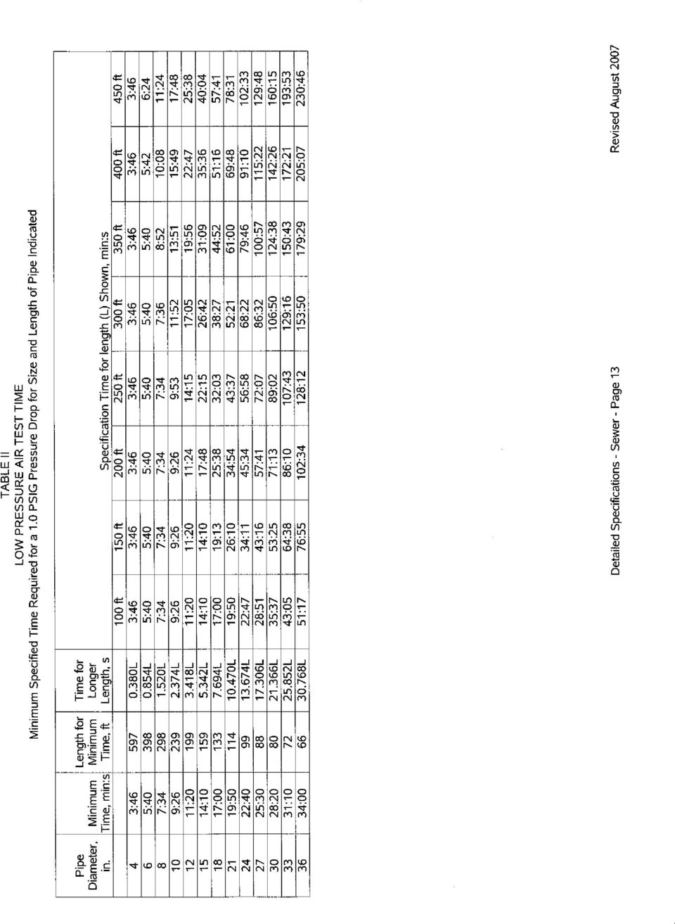
12 B. Low Pressure Air Testing All sanitary sewers 36 inches and smaller in diameter must pass a low pressure air test. The Contractor shall perform this test in the presence of the Engineer. Contractor shall supply all testing equipment. Equipment must be adequate and appropriate for application. All labor and equipment cost shall be borne by the Contractor. The apparatus for this low pressure air test shall be set up as indicated in the attached drawing, File #31 from the Standard Specifications for Sewer & Water Construction in Wisconsin. This air test is based upon an allowable leakage rate of ft 3 /min/ft 2 of internal surface area. Only after the sanitary sewers, including appurtenances and sanitary lateral stubs have been installed, backfilled, and cleaned, shall the Contractor proceed with an air test on the installed facilities. Low Pressure Air Test Procedure 1. The section of sewer line to be tested should be flushed and cleaned prior to conducting the low pressure air test. This serves to clean out any debris, wet the pipe, and produces more consistent results. 2. Isolate the section of the sewer line to be tested by means of inflatable stoppers or other suitable test plugs. Plug or cap the ends of all branches, laterals, tees, wyes, and stubs to be included in the test to prevent air leakage. One of the plugs should have an inlet tap, or other provision for connecting a hose to a portable air control source. 3. If the test section is below the ground water level, determine the height of the ground water above the top of the pipe at the upstream end of the test section. If the groundwater level is more than 2 feet above the top of the pipe at the upstream end, the air test should not be used. For every foot of ground water above the pipe spring line, increase the gage test pressures by 0.43 pounds per square inch. 4. Connect the air hose to the inlet tap and a portable air control source. The air equipment should consist of necessary valves and pressure gages to control the rate at which air flows into the test section and to enable monitoring of the air pressure within the test section. Also, the testing apparatus should be equipped with a pressure relief device set no higher than 9.0 psig to prevent the possibility of loading the test section with the full capacity of the compressor. 5. Add air slowly to the test section until the pressure inside the pipe is raised to 4.0 psig greater than the average back pressure of any ground water that may be over the pipe. Do not exceed 9.0 psig. 6. After a pressure of 4.0 psig is obtained, regulate the air supply so that the pressure is maintained between 3.5 and 4.0 psig (above the average ground water back pressure) for a period of two minutes. This allows the air temperature to stabilize in equilibrium with the temperature of the pipe walls. The pressure will normally drop slightly until temperature equilibrium is obtained. During this period, all plugs should be checked with a soap solution to detect any plug leakage. 7. Determine the rate of air loss by the time pressure drop method. After the two-minute air stabilization period, air is slowly introduced into the section of pipe to be tested until the pressure is raised to approximately 4.0 psig. The air supply is then disconnected and the test pressure allowed to decrease to 3.5 psig. The time required for the test pressure to drop from 3.5 psig to 2.5 psig is determined by means of a stopwatch and this time interval is then compared to the specification time as calculated from Table II to determine if the rate of air loss is within the allowable time limit. If the time is equal or greater than the times indicated in the tables, the pipe line shall be deemed acceptable. Detailed Specifications Sanitary Sewers Page 11 Revised August 2007

13

14
15

DIVISION 2 - SEWERAGE AND DRAINAGE SECTION 02720 - STORM DRAIN SYSTEMS PART 1 - GENERAL
 DIVISION 2 - SEWERAGE AND DRAINAGE SECTION 02720 - STORM DRAIN SYSTEMS PART 1 - GENERAL 1.01 DESCRIPTION A. Furnish and install all storm drains, including manholes, inlets, service lines and other appurtenant
SECTION 6 SANITARY SEWER MAIN 6.01 SCOPE
 6.01 SCOPE The work covered by this section of the specifications consists of the furnishing of all plant, labor, materials, equipment and supervision and performing all operations involved in the construction
State of Illinois Department Of Transportation CONSTRUCTION INSPECTOR S CHECKLIST FOR STORM SEWERS
 State of Illinois Department Of Transportation CONSTRUCTION INSPECTOR S CHECKLIST FOR STORM SEWERS While its use is not required, this checklist has been prepared to provide the field inspector a summary
32-02.05 Precast Manhole Sections and Castings. These items shall conform to Section 31, "Storm Drain Installation," of these Standard Provisions.
 SECTION 32: SANITARY SEWER INSTALLATION 32-01 SCOPE. The Work shall consist of furnishing and installing sewer mains, manholes, laterals, cleanout fittings and appurtenances; and testing, flushing and
SUBDRAINS AND FOOTING DRAIN COLLECTORS. A. Construct subdrains, subdrain cleanouts and outlets, and footing drain collectors.
 SUBDRAINS AND FOOTING DRAIN COLLECTORS PART 1 - GENERAL 1.01 SECTION INCLUDES A. Subdrains B. Subdrain Cleanouts and Outlets C. Footing Drain Collectors D. Storm Sewer Service and Connections 1.02 DESCRIPTION
Section 02702 SEWER PIPE INSTALLATION AND TESTING
 PART 1 - GENERAL Section 02702 SEWER PIPE INSTALLATION AND TESTING 1-1. SCOPE. This section covers the installation and testing of all sewer pipe furnished under the following specification sections: Concrete
SECTION 55 PIPE FOR STORM DRAINS AND CULVERTS (FAA D-701)
") SECTION 55 PIPE FOR STORM DRAINS AND CULVERTS (FAA D-701) 55-1 GENERAL The Contractor shall perform all work required by the plans for construction of pipe for storm drains, precast polymer trench drains
SECTION 55 PIPE FOR STORM DRAINS AND CULVERTS (FAA D-701) 55-1 GENERAL The Contractor shall perform all work required by the plans for construction of pipe for storm drains, precast polymer trench drains
SECTION 33 05 16.13 PRECAST CONCRETE UTILITY STRUCTURES
 SECTION 33 05 16.13 PRECAST CONCRETE PART 1 - GENERAL 1.01 SECTION INCLUDES A. This item shall consist of the construction of both sanitary and storm sewer precast concrete manholes in accordance with
CHAPTER 6 - SANITARY SEWER
 CHAPTER 6 - SANITARY SEWER 6.1 GENERAL This section covers the requirements for PVC plastic sewer pipe materials and installation in sanitary sewer construction. 6.2 PIPE PVC gravity sewer pipe and fittings
SECTION LS 2530 SANITARY SEWERS. A. General: Submit the following in accordance with The General Conditions.
 SECTION LS 2530 SANITARY SEWERS PART 1 GENERAL 1.1 SUBMITTALS A. General: Submit the following in accordance with The General Conditions. 1. Product data for drainage piping specialties. 2. Shop drawings
SECTION 02400 - STORM DRAIN SYSTEM
 SECTION 02400 - STORM DRAIN SYSTEM CONTENTS: Part 1 - General... 1 1.01 Work Included... 1 1.02 Related Requirements... 1 1.03 Reference Standards... 1 1.04 Quality Assurance... 1 1.05 Measurement And
SANITARY SEWER SPECIFICATIONS
 SANITARY SEWER SPECIFICATIONS OCTOBER 2003 HARVEST-MONROVIA WATER, SEWER, AND FIRE PROTECTION AUTHORITY SECTION 1.00 1.10 Purpose The purpose of this document is to assemble the sewer specifications, policies,
SECTION 08000 STORM DRAINAGE TABLE OF CONTENTS
 SECTION 08000 STORM DRAINAGE 08010 DESIGN A. Location B. Sizing TABLE OF CONTENTS 08020 MATERIALS A. Pipe Materials B. Structure Materials C. Installation D. Inlets and Outlets 08030 INSPECTIONS AND TESTING
SECTION 02630 STORM DRAINAGE SYSTEM
 SECTION 02630 PART 1 - GENERAL 1.01 DESCRIPTION A. Section includes specifications for storm drainage systems including modifications and connections to existing storm drainage systems. 1.02 REFERENCE
INDEX. Sec. No. Items Page Nos.
 INDEX Sec. No. Items Page Nos. 1. Types of Pipe............... MSSP- 2 2. Concrete Pipe............... MSSP- 2 thru MSSP-3 3. ABS and PVC Truss Pipe............... MSSP- 3 4. ABS and PVC Solid Wall Pipe...............
ARTICLE VI (ALTERNATE) STANDARD SPECIFICATIONS. for (PVC) SANITARY SEWER MAIN CONSTRUCTION
 STANDARD SPECIFICATIONS. for (PVC) SANITARY SEWER MAIN CONSTRUCTION") ARTICLE VI (ALTERNATE) STANDARD SPECIFICATIONS for (PVC) SANITARY SEWER MAIN CONSTRUCTION VI(A).1 General VI(A).2 Materials and Equipment VI(A).3 Installation of Sanitary Sewer Mains VI(A).4 Laying of
ARTICLE VI (ALTERNATE) STANDARD SPECIFICATIONS for (PVC) SANITARY SEWER MAIN CONSTRUCTION VI(A).1 General VI(A).2 Materials and Equipment VI(A).3 Installation of Sanitary Sewer Mains VI(A).4 Laying of
DESIGN AND CONSTRUCTION GUIDELINES AND STANDARDS DIVISION 33 UTILITIES 33 00 00 SITE UTILITIES
 SECTION INCLUDES Domestic Water Fire Water Service Water Well Sanitary Sewer Storm Drains Foundation Drainage RELATED SECTIONS 03 30 00 Concrete 21 00 00 Fire Suppression - Sprinklers 22 00 00 Plumbing
A. Contractor shall furnish, to the Engineer, all materials certifications available from the manufacturer for all required materials.
 PART 1 GENERAL 1.1 SCOPE A. This item shall include the work necessary for the installation of storm sewer line construction. B. Reference Section 3800 Trenching and Backfill and the General Conditions,
SECTION 02720 SANITARY SEWER AND STORM DRAIN SYSTEMS
 SECTION 02720 SANITARY SEWER AND STORM DRAIN SYSTEMS PART 1 GENERAL 1.01 SECTION INCLUDES A. The requirements for pipe material and installation in sewer and drainage collection systems. All materials
3. Contractor shall ensure that all permits are obtained prior to any construction. Contractor shall be responsible for all utility fees.
 The following shall serve as the minimum requirements for contractors performing work in relation to the Authority s potable water and sanitary sewer system(s), appurtenances and service connections. General:
STANDARD SPECIFICATIONS SECTION 03461 PRECAST REINFORCED CONCRETE MANHOLES AND MANHOLE BASES. 1. Structure Earthwork: 02200
 STANDARD SPECIFICATIONS SECTION 03461 PRECAST REINFORCED CONCRETE MANHOLES AND MANHOLE BASES PART 1 - GENERAL A. Description This section includes materials, testing, and installation of precast concrete
STANDARD SPECIFICATIONS SECTION 02701 INSTALLATION OF GRAVITY SEWER PIPELINES. 1. Trenching, Backfilling and Compacting: 02223
 STANDARD SPECIFICATIONS SECTION 02701 INSTALLATION OF GRAVITY SEWER PIPELINES PART 1 - GENERAL A. Description This section describes the installation of gravity sewer pipelines fabricated of vitrified
Wastewater Capital Projects Management Standard Construction Specification
 CITY AND COUNTY OF DENVER ENGINEERING DIVISION Wastewater Capital Projects Management Standard Construction Specification 10.1 Precast Concrete Pipe 10.1.1 General This section covers material requirements,
Bethel Township Municipal Authority (BTMA) RESIDENTIAL SEWER CONNECTION MANUAL
 RESIDENTIAL SEWER CONNECTION MANUAL") 155 E. Front Street (rear) Lititz, PA 17543 Phone (717) 625-1930 Fax (717) 625-1931 Bethel Township Municipal Authority (BTMA) RESIDENTIAL SEWER CONNECTION MANUAL CONSTRUCTION SPECIFICATIONS AND DETAILS
155 E. Front Street (rear) Lititz, PA 17543 Phone (717) 625-1930 Fax (717) 625-1931 Bethel Township Municipal Authority (BTMA) RESIDENTIAL SEWER CONNECTION MANUAL CONSTRUCTION SPECIFICATIONS AND DETAILS
FY11 Sanitary Sewer Main Rehab and Point Repair Bid Tabulation
 644-10-569 Page 1 of 9 1 FOR CLEANING AND TELEVISING EXISTING SEWERS, AS SPECIFIED, ANY REQUIRED CLEANING, ANY LOCATION, ANY LENGTH OF SEWER, COMPLETE IN PLACE, FOR VARIOUS PIPE DIAMETERS. A. EXISTING
SECTION 9.02 BUILDING SUBSURFACE DRAINS (PERIMETER, ETC.)
") CHAPTER 9 SEWER / STORM DRAIN / IRRIGATION LINES SECTION 9.01 GENERAL This section covers the requirements for piping materials and installation of Lehi City sewer, storm drainage and irrigation collection
CHAPTER 9 SEWER / STORM DRAIN / IRRIGATION LINES SECTION 9.01 GENERAL This section covers the requirements for piping materials and installation of Lehi City sewer, storm drainage and irrigation collection
SECTION 33 31 00.11 GRAVITY SANITARY SEWERS
 SECTION 33 31 00.11 GRAVITY SANITARY SEWERS PART 1: GENERAL 1.01 SCOPE A. Gravity sanitary sewers and appurtenances. 1.02 SUBMITTALS A. Conform to requirements of Section 01 33 00 Submittals. B. Submit
SECTION 33 41 13 PUBLIC STORM UTILITY DRAINAGE PIPING
 SECTION 33 41 13 PUBLIC STORM PART 1 - GENERAL 1.01 SECTION INCLUDES A. Storm drainage piping, fittings, and accessories at proposed station areas and locations other than under and immediately adjacent
AIR RELEASE, CLEANOUT, AND SEWER MANHOLES
 AIR RELEASE, CLEANOUT, AND SEWER MANHOLES **From Hartford IM BLDG(10) DESCRIPTION. This work shall consist of the construction of air release, cleanout, and sanitary sewer manholes; and the furnishing
SECTION 02530 STORM DRAINAGE STRUCTURES. 1. Trench excavation, backfill, and compaction; Section 02250.
 02530-1 of 5 SECTION 02530 STORM DRAINAGE STRUCTURES 02530.01 GENERAL A. Description Storm drainage structure construction shall include, but not necessarily be limited to, furnishing and installing or
SECTION 02401 - SANITARY SEWER PIPE
 PART 1 - GENERAL 1.1 DESCRIPTION A. The WORK under this Section includes providing all labor, materials, tools and equipment necessary for furnishing and installing sanitary sewer pipe, in accordance with
The work of this Section includes furnishing and installing Reinforced Concrete Pressure Pipe as shown on the Drawings and as specified.
 Section 33 0200- Page 1 of 4 PART 1 - GENERAL 1.1 DESCRIPTION OF WORK The work of this Section includes furnishing and installing Reinforced Concrete Pressure Pipe as shown on the Drawings and as specified.
FY08 SEWER POINT REPAIRS BID TABULATION
 6-07-831 Page 1 of 12 1 FOR CLEANING AND TELEVISING EXISTING SEWERS, AS SPECIFIED, ANY REQUIRED CLEANING, ANY LOCATION, ANY LENGTH OF SEWER, COMPLETE IN PLACE, FOR VARIOUS PIPE DIAMETERS. A. EXISTING "
SECTION 33 11 00.11 POLYVINYL CHLORIDE (PVC) PIPE
 PIPE") SECTION 33 11 00.11 POLYVINYL CHLORIDE (PVC) PIPE PART 1: GENERAL 1.01 SECTION INCLUDES PVC pressure pipe and fabricated fittings in nominal sizes 4-inches through 12-inches with cast iron pipe equivalent
SECTION 33 11 00.11 POLYVINYL CHLORIDE (PVC) PIPE PART 1: GENERAL 1.01 SECTION INCLUDES PVC pressure pipe and fabricated fittings in nominal sizes 4-inches through 12-inches with cast iron pipe equivalent
Section 2100-Trenching and Tunneling
 SECTION 5200 - STORM SEWER PART 1 - GENERAL 1.01 SCOPE: This Section covers installation of storm sewer mains and culverts. Topics include permits and fees, trench widths, pipe laying, bedding, initial
City of Virginia Beach Public Utilities HRPDC Regional Construction Standards, 5 TH Edition Amendments May 19, 2014
 City of Virginia Beach Public Utilities HRPDC Regional Construction Standards, 5 TH Edition Amendments May 19, 2014 Section Subsection Name Date Modification Division 1 All subsections General Provisions
DIVISION 4300 STORM DRAINAGE
 DIVISION 4300 STORM DRAINAGE SECTION 4305 STORM SEWER PART 1 - GENERAL 1.01 SCOPE This section covers the construction of storm sewers for the collection and transport of stormwater runoff. 1.02 REFERENCES
SECTION 36 - CAST-IN-PLACE CONCRETE PIPE (CIPCP) TABLE OF CONTENTS
 TABLE OF CONTENTS") SECTION 36 - CAST-IN-PLACE CONCRETE PIPE (CIPCP) TABLE OF CONTENTS Section Page 36-1 GENERAL... 36.1 36-2 PIPEMAKING EQUIPMENT... 36.1 36-3 TRENCH EXCAVATION... 36.1 36-4 SPECIAL FOUNDATION TREATMENT...
SECTION 36 - CAST-IN-PLACE CONCRETE PIPE (CIPCP) TABLE OF CONTENTS Section Page 36-1 GENERAL... 36.1 36-2 PIPEMAKING EQUIPMENT... 36.1 36-3 TRENCH EXCAVATION... 36.1 36-4 SPECIAL FOUNDATION TREATMENT...
SECTION 02763 POINT REPAIRS TO SANITARY SEWERS. A. Repairs to existing sewer lines by replacing short lengths of failed pipe.
 SECTION 02763 PART 1 G E N E R A L 1.01 SECTION INCLUDES A. Repairs to existing sewer lines by replacing short lengths of failed pipe. 1.02 UNIT PRICES A. Measurement for point repairs is on a unit price
SECTION 02732 BUILDING SEWERS. B. Connection of building sanitary drainage system to municipal sewers.
 SECTION 02732 BUILDING SEWERS PART 1 GENERAL 1.01 SECTION INCLUDES A. Lateral piping, fittings, and accessories. B. Connection of building sanitary drainage system to municipal sewers. 1.02 REGULATORY
San Antonio Water System Standard Specifications for Construction ITEM NO. 1100 SLIP-LINING SANITARY SEWERS
 ITEM NO. 1100 SLIP-LINING SANITARY SEWERS 1100.1 DESCRIPTION: This item shall consist of slip-lining sanitary sewer pipe, which is accomplished by pulling or pushing liner pipe into existing sewers by
LS 2540 SEWER LATERALS AND INSPECTION TEES
 LS 2540 SEWER LATERALS AND INSPECTION TEES A. Summary B. Submittals C. Site Information D. Sewer Pipe and Fittings E. Lateral Locations F. Lateral Installation G. Inspection Tee Installation H. Removal
TABLE OF CONTENTS SECTION 500 SANITARY SEWER AND FORCE MAIN
 TABLE OF CONTENTS SECTION 500 SANITARY SEWER AND FORCE MAIN Starts on Page 500 GENERAL... 2 501 MATERIALS... 2 502 CONSTRUCTION PROCEDURES... 7 503 ABANDONMENT OF EXISTING SANITARY SEWER FACILITIES...
900 SEWERAGE WORK ITEM 901 - PIPE SEWERS COMPLETE IN PLACE
 900 SEWERAGE WORK ITEM 901 - PIPE SEWERS COMPLETE IN PLACE 901.01 Description 901.02 Materials and Material Handling 901.03 Excavation 901.04 Limit as to Width of Trench 901.05 Unauthorized Excavation
STANDARD SPECIFICATIONS FOR PRIVATE BUILDING SEWER LINES IN PUBLIC RIGHT-OF-WAY
 STANDARD SPECIFICATIONS FOR PRIVATE BUILDING SEWER LINES IN PUBLIC RIGHT-OF-WAY Approved and adopted as Official Document Number 800576 this 10th day of December, 1980 Donald R. Boyd, P.E., Director Water
TABLE OF CONTENTS. Manhole, Frame, and Cover Installation (includes Drop Manhole) Additional Manhole Depth
 Additional Manhole Depth") TABLE OF CONTENTS NO. MP-1 MP-2 MP-3 MP-4 MP-4.01 MP-4.02 MP-4.03 MP-5 MP-5.01 MP-5.02 MP-5.03 MP-5.04 MP-5.05 MP-5.06 MP-5.07 MP-5.08 MP-5.11 MP-5.12 MP-5.13 MP-5.14 MP-5.15 MP-5.16 MP-5.18 MP-5.19 MP-5.20
TABLE OF CONTENTS NO. MP-1 MP-2 MP-3 MP-4 MP-4.01 MP-4.02 MP-4.03 MP-5 MP-5.01 MP-5.02 MP-5.03 MP-5.04 MP-5.05 MP-5.06 MP-5.07 MP-5.08 MP-5.11 MP-5.12 MP-5.13 MP-5.14 MP-5.15 MP-5.16 MP-5.18 MP-5.19 MP-5.20
SECTION 724 PIPE CULVERTS
 SECTION 724 PIPE CULVERTS 724.1 Description. This work shall consist of providing pipe or pipe arch of the diameter or shape designated, laid upon a firm bed and backfilled as specified. Where appropriate
San Antonio Water System Standard Specifications for Construction ITEM NO. 1103 POINT REPAIRS AND OBSTRUCTION REMOVALS
 ITEM NO. 1103 POINT REPAIRS AND OBSTRUCTION REMOVALS 1103.1 DESCRIPTION: 1. Repair of sanitary sewer lines by replacing short lengths of failed pipe with new pipe. 2. Repair of service laterals located
ARTICLE II (2) ARTICLE II - REQUIRED USE OF PUBLIC SEWERS. PARAGRAPH 020001 Purpose and Application.
 ARTICLE II - REQUIRED USE OF PUBLIC SEWERS. PARAGRAPH 020001 Purpose and Application.") ARTICLE II - REQUIRED USE OF PUBLIC SEWERS. PARAGRAPH 020001 Purpose and Application. Article II provides rules governing the allowable connection to the City POTW and the construction and inspection of
ARTICLE II - REQUIRED USE OF PUBLIC SEWERS. PARAGRAPH 020001 Purpose and Application. Article II provides rules governing the allowable connection to the City POTW and the construction and inspection of
SECTION 5: SANITARY SEWER SYSTEM DESIGN
 SECTION 5: SANITARY SEWER SYSTEM DESIGN 5.01 GENERAL Sanitary sewer improvements shall be designed to serve the ultimate level of City development as defined in the General Plan and the Wastewater Facilities
SERVICE LINE EXTENSION AND SERVICE LINE CONNECTION CONDENSED SANITARY SEWER SYSTEM INSTALLATION SPECIFICATIONS
 1001 SOUTH LEECHBURG HILL LEECHBURG, PA 15656 Phone: 724-845-9355 Fax: 724-845-1186 SERVICE LINE EXTENSION AND SERVICE LINE CONNECTION CONDENSED SANITARY SEWER SYSTEM INSTALLATION SPECIFICATIONS 1. General
TECHNICAL SPECIFICATIONS GRAVITY AND PRESSURE SEWER LINE AND MATERIALS
 TECHNICAL SPECIFICATIONS GRAVITY AND PRESSURE SEWER LINE AND MATERIALS Scope of Work Work performed under this contract shall consist of furnishing and installing, complete and ready for service, the sewer
SECTION 03400 PRECAST CONCRETE STRUCTURES
 PART 1 GENERAL 1.01 SCOPE OF WORK A. Furnish all labor, materials, and equipment required to install precast concrete manholes, sanitary leaching rings, pump station, valve chamber, structures, frames,
Exhibit A. Rules and Regulations for House Connections and Sewer Extensions
 The purpose of this application example is to provide assistance to small and medium sized rural communities in the drafting of documents necessary for the efficient operation of water, wastewater, and
CCU Engineering Specifications. Section 003300 PRECAST CONCRETE PRODUCTS
 CCU Engineering Specifications Section 003300 Effective Date: Nov. 1st, 2011 Page 1 of 5 PRECAST CONCRETE PRODUCTS PART 1 - GENERAL The following specification is intended for use for the design, selection
LOGAN TOWNSHIP MUNICIPAL UTILITIES AUTHORITY DESIGN, CONSTRUCTION, INSPECTION AND TESTING MANUAL
 LOGAN TOWNSHIP MUNICIPAL UTILITIES AUTHORITY DESIGN, CONSTRUCTION, INSPECTION AND TESTING MANUAL February 2010 LOGAN TOWNSHIP UTILITIES AUTHORITY INSPECTION AND TESTING PROCEDURE TABLE OF CONTENTS SECTION
San Antonio Water System Standard Specifications for Construction ITEM NO. 854 SANITARY SEWER LATERALS
 San Antonio Water System Standard Specifications for Construction ITEM NO. 854 SANITARY SEWER LATERALS 854.1 DESCRIPTION: This item shall govern sanitary sewer laterals installed in accordance with these
C. Section 014510 TESTING LABORATORY SERVICE.
 SECTION 014500 QUALITY CONTROL PART 1 GENERAL 1.01 RELATED REQUIREMENTS A. Drawings and General Provisions of Contract, including General and Special Conditions and other Division 1 Specification Sections,
Section 402. STORM SEWERS
 402.02 Section 402. STORM SEWERS 402.01. Description. This work consists of constructing storm sewers of the size and class required, including excavation, bedding, and backfill. 402.02. Materials. Provide
The Manitoba Water Services Board SECTION 027030 Standard Construction Specifications September 2013 Page 1 of 21
 September 2013 Page 1 of 21 Part 1 General 1.1 DESCRIPTION OF WORK.1 The work described herein shall consist of the construction of sewers including: the supply and installation of pipe, saddles, tees,
Beacon Hill Sewer District Standard Specifications
 Beacon Hill Sewer District Standard Specifications Residential Gravity Side Sewer Including Design Criteria and Standard Construction Drawings Residential Gravity Side Sewer Design Criteria 1. Provisions
CLEANING, INSPECTION, AND TESTING OF SEWERS
 CLEANING, INSPECTION, AND TESTING OF SEWERS PART 1 - GENERAL 1.01 SECTION INCLUDES A. Cleaning, Inspecting, and Testing Sanitary Sewers B. Cleaning, Inspecting, and Testing Storm Sewers C. Cleaning and
EXHIBIT "A. Technical Specifications for Water and Sewer Service Lines
 EXHIBIT "A Technical Specifications for Water and Sewer Service Lines Water and Sewer Line Bedding and Backfill: Drawings show cross-section of trench, pipe laid on top of 6" min. bedding material, bedding
Specification for Pipe Bursting Gravity Sewer Mains with HDPE Pipe
 Specification for Pipe Bursting Gravity Sewer Mains with HDPE Pipe 1. GENERAL The following supplemental sewer main specifications are intended to address the installation of high-density polyethylene
CITY OF BEVERLY RULES AND REGULATIONS - SEWER SYSTEM TESTING. General
 General All sanitary sewers, manholes and force mains shall be acceptance tested, as hereinafter specified in the presence of a City representative. Acceptance testing shall be performed after backfilling
SECTION 02150 REMOVAL OR ABANDONMENT OF EXISTING UTILITIES AND UNDERGROUND STRUCTURES. 1. Trench excavation, backfill, and compaction; Section 02250.
 02150-1 of 6 SECTION 02150 REMOVAL OR ABANDONMENT OF EXISTING 02150.01 GENERAL A. Description Removal or abandonment of existing utilities and underground structures shall include, but not necessarily
CW 2130 - GRAVITY SEWERS TABLE OF CONTENTS
 August 2010 CW 2130 - GRAVITY SEWERS TABLE OF CONTENTS 1. DESCRIPTION... 1 1.1 General... 1 1.2 Definitions... 1 1.3 Referenced Standard Construction Specifications... 1 1.4 Referenced Standard Details...
SECTION 200: STORM SEWER CONSTRUCTION STANDARDS
 SECTION 200: STORM SEWER CONSTRUCTION STANDARDS Page No. Description 200-2 201 GENERAL 200-2 201.1 SPECIFICATIONS 200-2 201.2 CONNECTION TO EXISTING FACILITIES 200-3 202 MATERIALS 200-3 202.1 PIPES 200-4
SECTION 15076 CEMENT-MORTAR LINED AND COATED STEEL PIPE
 SECTION 15076 CEMENT-MORTAR LINED AND COATED (CML&C) STEEL PIPE PART 1 GENERAL 1.01 DESCRIPTION This section designates the requirements for steel pipe fabrication, test in shop, installation of steel
SECTION 221413 FACILITY STORM DRAINAGE PIPING
 SECTION 221413 FACILITY STORM DRAINAGE PIPING PART 1 - GENERAL 1.01 RELATED DOCUMENTS A. Drawings and general provisions of the Contract, including General and Supplementary Conditions and Division 01
SECTION 9. All sewer laterals shall tie into the sewer main lines unless approved by the City Engineer.
 SECTION 9 SEWER/DRAINAGE LINES 9.1 GENERAL This section covers the requirements for piping materials and installation in the Cedar Hills City sewer and drainage collection system. All materials and workmanship
September 2012 Brunswick County Engineering Department Revision 1.0. Technical Specification 020.01 GRAVITY SANITARY SEWER SYSTEM
 1.0 General Technical Specification 020.01 GRAVITY SANITARY SEWER SYSTEM a) It is the intent of this specification to ensure that all gravity sewer system infrastructure constructed within the service
ASTM C76, Class III, Wall B, except as modified herein. Clean natural sand, ASTM C33. Artificial or manufactured sand will not be permitted.
 SECTION 3000 - SANITARY SEWERS 3001 SCOPE. This section applies to sanitary sewer construction and shall consist of furnishing all labor, materials, and equipment for the complete installation of sewers
08003-1 WATER SERVICE 2
 08003_Mar08_2011.pdf Page 1 of 7 INDEX Page 08003-1 WATER SERVICE 2 1.1 Pipe 2 1.1.1 Copper 2 1.1.2 Polyethylene 2 1.2 Valves and Fittings 2 1.2.1 Main Stops 3 1.2.2 Curb Stops 3 1.2.3 Curb Box 3 1.2.4
SANITARY GRAVITY SEWER LINE TESTING. B. Section 02732 CCTV Inspection of Gravity Sewer Lines
 PART 1 GENERAL 1.1 SECTION INCLUDES A. Low Pressure Air Test B. Deflection Test 1.2 RELATED SECTIONS A. Section 02730 Sanitary Gravity Sewer Lines B. Section 02732 CCTV Inspection of Gravity Sewer Lines
Model Specification 509 DRISCOPLEX 4200 and DRISCOPLEX 4300 Gravity Flow Sanitary Sewer
 Model Specification 509 DRISCOPLEX 4200 and DRISCOPLEX 4300 Gravity Flow Sanitary Sewer The user may choose to adopt part or all of this Model Specification; however, the user should ensure that all parts
SECTION 21 REHABILITATION OF SANITARY SEWER MAINS BY THE PIPE BURSTING AND TRENCHLESS PIPE REPLACEMENT METHOD
 SECTION 21 REHABILITATION OF SANITARY SEWER MAINS BY THE PIPE BURSTING AND TRENCHLESS PIPE REPLACEMENT METHOD 21.01 SCOPE: It is the intent of the Specification to define the approved methods and materials
SANITARY SEWER SERVICE CONNECTION INSTRUCTIONS
 1 SANITARY SEWER SERVICE CONNECTION INSTRUCTIONS TABLE OF CONTENTS I. Introduction II. General Information and Requirements A. Applying for Sewer connection B. Excavation C. Cutting Concrete and Asphalt
53.03 MATERIALS FOR SEWER LINER PIPE AND FITTINGS: The following materials are approved for installation in sanitary sewer lines:
 Division 53: Slip-Lining of Existing Sewer Line 53.01 GENERAL: This section includes all labor, materials, transportation, equipment necessary to rehabilitate by means of Instituform deteriorated sections
SECTION 7- STORM SEWER
 SECTION 7- STORM SEWER 7.1. STORM SEWERS.... 7-1 7.2. SUMP DRAINS... 7-3 7.3. CATCH BASINS... 7-3 7.4. MANHOLES... 7-4 7.5. STORM SEWER CALCULATIONS... 7-4 7.6. CULVERTS AND BRIDGES... 7-5 7.7. OPEN CHANNELS...
SECTION 3 SANITARY SEWER DESIGN
 SECTION 3 SANITARY SEWER DESIGN 3.1 GENERAL DESIGN CRITERIA 3.1.1 Requirement for Sanitary Sewer 3.1.2 Design Approval 3.1.3 IEPA Permit Required 3.1.4 Differentiation Between Public and Private Sanitary
SECTION IV - TESTS AND INSPECTIONS PART 1 - GENERAL. 1.01 Testing - General
 SECTION IV - TESTS AND INSPECTIONS PART 1 - GENERAL 1.01 Testing - General Testing shall be of the type and frequency described in each section and summarized in Item 1 of this section. In addition to
STANDARD CONSTRUCTION SPECIFICATIONS FOR SANITARY SEWERS DIVISION 50 INDEX
 STANDARD CONSTRUCTION SPECIFICATIONS FOR SANITARY SEWERS DIVISION 50 INDEX SECTION 50.01 GENERAL... 1 Article 1.1 Scope of Work... 1 Article 1.2 Applicable Standards... 1 Article 1.3 Surveys... 2 Article
Sanitary Sewer Mains and Services
 Sewer Title Sanitary Sewer Mains and Services STitle Sewer Table of Contents "CORRECTIVE PERIOD & INSPECTION FOR SANITARY SEWERS & SERVICES"... 1 1. TERM OF GUARANTEE... 1 2. CONTRACTOR LICENSE AND PERMITS...
SECTION 603 SANITARY SEWER FORCE MAINS
 SECTION 603 SANITARY SEWER FORCE MAINS 1. GENERAL Pipelines for sanitary sewer force main systems shall conform to the following specifications and shall be installed at the locations indicated on the
Section 5 Sanitary Sewer
 5.01.000 GENERAL 5.01.010 Definition Sanitary sewerage refers to waste water derived from domestic, commercial and industrial pretreated waste to which storm, surface, and ground water are not intentionally
SECTION 02110 - ASBESTOS CEMENT PIPE REPAIRS, DEMOLITION, AND DISPOSAL
 SECTION 02110 - ASBESTOS CEMENT PIPE REPAIRS, DEMOLITION, AND DISPOSAL PART 1 - GENERAL 1.1 WORK INCLUDED IN THIS SECTION A. The WORK of this Section includes the repair, demolition, and disposal of asbestos
Close-Out Documents... 9
 Water and Sanitary Sewer Service Connection Requirements Service Connection Requirements... 1 Application for Services... 2 Water Meter Application... 2 Wet Tap/Tie-in Connection Requirements... 3 Meter
CONTENTS. Yale University Design Standards. Underground Electrical Duct Bank. A. Summary. B. System Design and Performance Requirements
 16600 Underground Electrical Duct Bank This document provides design standards only, and is not intended for use, in whole or in part, as a specification. Do not copy this information verbatim in specifications
SECTION 33 41 00 REINFORCED CONCRETE PIPE. A. The following is a list of SPECIFICATIONS, which may be related to this section:
 SECTION 33 41 00 REINFORCED CONCRETE PIPE PART 1 GENERAL 1.01 SECTION INCLUDES A. This section includes construction of reinforced concrete pipe for storm drainage, culverts, and sanitary sewer, including
Stormwater/Wetland Pond Construction Inspection Checklist
 : Construction Inspection ChecklistsTools Stormwater/Wetland Pond Construction Inspection Checklist Project: Location: Site Status: Date: Time: Inspector: SATISFACTORY/ UNSATISFACTORY COMMENTS Pre-Construction/Materials
The checklist utilized by the Authority will be similar to that which is shown below. Project Name: Location: Consulting Engineering Firm:
 Page 1 of 6 Section 1. PURPOSE This policy is an Engineering checklist of the Local Review Program for sanitary sewer improvement projects by the Bedford Regional Water Authority ( Authority ). Section
CHAPTER 5. Storm Sewer
 CHAPTER 5 Storm Sewer A. Introduction All proposed developments shall have a properly designed and constructed storm water conveyance system. This chapter deals only with the conveyance system. Storm water
STORM DRAIN DESIGN AND CONSTRUCTION STANDARDS & SPECIFICATIONS 400 SERIES
 CITY OF PETALUMA STORM DRAIN DESIGN AND CONSTRUCTION STANDARDS & SPECIFICATIONS 400 SERIES AUGUST 1999 Revised 10/98 City of Petaluma Petaluma, California STORM DRAIN INSTALLATION DETAIL
8.01 STORM SEWERS, CATCH BASIN LEADS, AND EXTENSIONS
 8.01 STORM SEWERS, CATCH BASIN LEADS, AND EXTENSIONS 8.01.01 Description This work shall consist of installing lines of storm sewer pipe of the required inside diameter, and the necessary appurtenances,
SUMMARY OF PUBLIC WORK STANDARD SPECIFICATION REVISIONS 2016
 SUMMARY OF PUBLIC WORK STANDARD SPECIFICATION REVISIONS 2016 102.5 Bid Deposits The City of Madison bid deposit form is required for all bids unless a Biennial Bid Bond is on file or check deposit is used.
SEPTIC SYSTEM CONSTRUCTION REQUIREMENTS ST. MARY S COUNTY HEALTH DEPARTMENT
 SEPTIC SYSTEM CONSTRUCTION REQUIREMENTS ST. MARY S COUNTY HEALTH DEPARTMENT The following are minimum requirements for installation of conventional trench sewage disposal systems in St. Mary s County,
OAR52 A-1 (September, 1981)
") APPENDIX A SEWER PIPELINES (1) MINIMUM REQUIREMENTS FOR SEWER - PIPELINES (a) Capacity: Sewers shall be of such diameter as to pass without overflow, bypass, or back flow onto damageable property of a
APPENDIX A SEWER PIPELINES (1) MINIMUM REQUIREMENTS FOR SEWER - PIPELINES (a) Capacity: Sewers shall be of such diameter as to pass without overflow, bypass, or back flow onto damageable property of a
3A-1---------------------------------General Information A. Concepts... 1 B. Conditions... 1
 Statewide Urban Design and Specifications Table of Contents Design Manual Chapter 3 Sanitary Sewers Table of Contents TOC Chapter 3 Sanitary Sewers 3A General Information 3A-1---------------------------------General
SEDIMENT/STORMWATER MANAGEMENT BASIN CONSTRUCTION CHECKLIST
 SEDIMENT/STORMWATER MANAGEMENT BASIN CONSTRUCTION CHECKLIST For permanent structures per Delaware SCS Pond Code 378 and Delaware Sediment and Stormwater Regulations KEY PROJECT INFORMATION Item meets standard