Bachelor Thesis of science course in Electrical engineering of Aachen University of Applied Sciences, Campus Jülich
|
|
|
- Owen Boone
- 8 years ago
- Views:
Transcription
1 Bachelor Thesis of science course in Electrical engineering of Aachen University of Applied Sciences, Campus Jülich Optical Scanning of an image plate by 2D-laserscanner with integrated data logging Yingna Wang Mar. 2006

2 This Bachelor thesis has been carried out at the e of solid state research() of the Research Center Jülich(FZ Jülich) Professor Tutor: Technic helper: Prof. Dr. Th. Brükel Prof. Dr. Hans-Josef Ackermann Klaus Bussmann This thesis was supervised by: I certify that this work has been carried out and written up entirely by myself. No literature references and resources other than those cited have been used. Jülich, Mar. 2006

3 1. Introduction of the whole system Theory About LabVIEW Introduction of LabVIEW Basic use Application System Set-up List of equipments Optical Scanners Mini SAX GSI Lumonics SC2000 Digital Scan Controller About Laser Hooking up the system GSI Lumonics SC2000 Support Program Introduction of GSI Group Introduction of the Support Program Command Reference Operation for Scan controller Application

4 6. Use the SubVIs to build own Labview program Control the movement of Laser SubVIs from GSI Lumonics SC2000 Driver ComConfig set Correction the Laser Position mm 100mm Image plate scan Data Process 2D array into Intensity Graph Simulate the Data with a Voltmeter Conclusions Appendix References

5 Chapter 1 Introduction of the whole system The project is to scan a max. 600mm 600mm large area neutron image plate every 1mm grid with an installation of YAG-Laser beam that was displaced by a moving magnet motor controlled reflector system. For each grid point there will be an analog measure value and then saved into a memory. It should be also possible that the data of each point from the memory can be read out and displayed into a graph. The displace system and the electronic components of the GSI-Lumonics Group must work with the Class-3B-Laser mechanically to set up an experiment. The Software used in the project will be the LabVIEW of the National Instrument Company related with the free interpreter program language Python. Practical work procedure: 1. Learn the Software LabVIEW to be familiar with using and also building programs. 2. Set-up the hardware system with the electronic components of the GSI- Lumonics Group and connect with the host computer with LabVIEW. 3. Install the program CLI.exe (Command Line Interface) from the CD of GSI Group, be familiar with the commands used in the program to control the system. 4. Use the LabVIEW to build up a second program to control the system with the subvis that contained in the CD. 5. Also write one part program that can acquire and proceed the data to be displayed into a graph

6 The original Project in -FZ Jülich: People involved: Th.Brückel, A.Ioffe, E.Küssel,S.Massalovitch, M.Schlapp*, B.Schmitz Forschungszentrum Jülich GmbH, Festkörperforschung, - *TU Darmstadt, Fachbereich Material- und Geowissenschaften, Fachgebiet Elektronische Materialeigenschaften We are constructing a two-dimensional position sensitive detector that will operate at the triple-axis spectrometer / diffractometer SV30 at the FZ Jülich. The main features of this detector should be: the spatial resolution of about 1 mm; the large-area (~500x500 mm2) that provides a wide observation angle (up to 60 degree) both in vertical and horizontal direction; a high efficiency for thermal neutrons; the ability to operate in a relatively high gamma-background environment; the linear response in a wide dynamic range; relatively low price. We are considering a neutron detector based upon hotostimulable storage phosphor doped by a neutron converter. However, the image plates with the Gd converter which are only commercially available, are rather sensitive to the gamma radiation and do not satisfy our requirements. Therefore, we are developing a new approach based upon the use of a 6 Li converter that is insensitive to the gamma background. Our analysis shows that a low (with respect to the Gd converter) neutron capture cross section of 6 Li converter can be compensated by the higher released energy and a proper optimization of the parameters of the image plate and the read-out system. This research is carried out in collaboration with TU-Darmstadt, where the new different phosphors are under investigation (Prof. H. von Seggern, M.Schlapp)
 that provides a wide observation angle (up to 60 degree) both in vertical and")
7 Chapter 2 Theory Neutron image plates (NIPs) have found widespread application as neutron detectors for single-crystal and powder diffraction, small-angle scattering and tomography. After neutron exposure, the image plate can be read out by scanning with a laser. Commercially available NIPs consist of a powder mixture of BaFBr : Eu2+ and Gd2O3 dispersed in a polymer matrix and supported by a flexible polymer sheet. Since BaFBr : Eu2+ is an excellent x-ray storage phosphor, these NIPs are particularly sensitive to γ radiation which is always present as a background radiation in neutron experiments. In this work we present results on NIPs consisting of KCl : Eu2+ and LiF that were fabricated into ceramic image plates in which the alkali halides act as a self-supporting matrix without the necessity for using a polymeric binder. An advantage of this type of NIP is the significantly reduced γ -sensitivity. However, the much lower neutron absorption cross section of LiF compared with Gd2O3 demands a thicker image plate for obtaining comparable neutron absorption. The greater thickness of the NIP inevitably leads to a loss in spatial resolution of the image plate. However, this reduction - 3 -

8 in resolution can be restricted by a novel image plate concept in which a ceramic structure with square cells (referred to as a honeycomb ) is embedded in the NIP, resulting in a pixelated image plate. In such a NIP the read-out light is confined to the particular illuminated pixel, decoupling the spatial resolution from the optical properties of the image plate material and morphology. In this work, a comparison of experimentally determined and simulated spatial resolutions of pixelated and unstructured image plates for a fixed read-out laser intensity is presented, as well as simulations of the properties of these NIPs at higher laser powers. -<Pixelated neutron image plates> More details: Chapter 3 About LabVIEW 3.1 Introduction of LabVIEW What is LabVIEW? National Instruments LabVIEW is an industry-leading software tool for designing test, measurement, and control systems. Since its introduction in 1986, engineers and scientists worldwide who have relied on NI LabVIEW graphical development for projects throughout the product design cycle have gained improved quality, shorter time to market, and greater engineering and manufacturing efficiency. By using the integrated LabVIEW environment to interface with real-world signals, analyze data for meaningful information, and share results, you can boost productivity throughout your organization. Because LabVIEW has the flexibility of a programming language combined with built-in tools designed specifically for test, measurement, and control, you can create applications that range from simple temperature monitoring to sophisticated simulation and control systems. No matter your project, LabVIEW has the tools necessary to make you successful quickly

9 - LabVIEW is a powerful and flexible development tool designed specifically for the needs of scientists and engineers. It used the graphical programming language G to create programs called virtual instruments (VIs) in a flowchartlike form called a block diagram. The user interacts with the program through the front panel. LabVIEW has many build-in functions to facilitate the programming process. Block diagram: Pictorial representation of a program or algorithm. In G, the block diagram, which consists of executable icons, called nodes, and wires that carry data between the nodes, is the source code for the VI. Front panel: The interactive interface of a VI. Modeled from the front panel of physical instruments, it is composed of switches, slides, meters, graphs, charts, gauges, LEDs, and other controls and indicators

10 3.2 Basic use Example01: For loop and while loop For loop: Calculate 5 times, the last time i=4, the indicator display the result i+1=5. While loop: Keep on calculate till press the stop button, if the i= at that time, the indicator display the result i+1=

11 For loop in other programming language: Java for (int i=0; i<10; i++){ System.out.println("The value of 'i' is " + i ); } C++ int i; for (i=0; i<10; i++){ cout << "The value of 'i' is " << i << endl; } Python for i in [1,2,3,4,5,6,7,8,9,10]: print "The value of 'i' is", i While loop in other programming language: Java int i = 0; while (i < 10){ System.out.println("The value of 'i' is " + i); i++; } C++ int i = 0; while (i < 10){ cout << "The value of 'i' is " << i << endl; i++; }him Python i = 0 while i < 10: print "The value of 'i' is", i i = i
![[1,2,3,4,5,6,7,8,9,10]: print "The value of 'i' is", i While loop in other programming language: Java int i = 0; while (i < 10){ System.out.](/docs-images/40/1294827/images/page_11.jpg "println(\"The value of 'i' is \" + i); i++; } C++ int i = 0; while (i < 10){ cout << \"The value of 'i' is \" << i << endl; i++; }him Python i")
12 Example02: plot a circle using an XY Graph. The function of a circle is: x²+y²=r² r²*sin²a+r²*cos²a=r² x=r*sina y=r*cosa - 8 -

13 Example03: Data acquisition (DAQ) Data acquisition is the process of gathering information in an automated fashion from analog and digital measurement sources such as sensors and devices under test. Data acquisition uses a combination of PC-based measurement hardware and software to provide a flexible, user-defined measurement system. When you place the DAQ Assistant Express VI on the block diagram, the DAQ Assistant automatically appears. The DAQ Assistant is a graphical interface that we can use to configure measurement tasks and channels

14 - 10 -
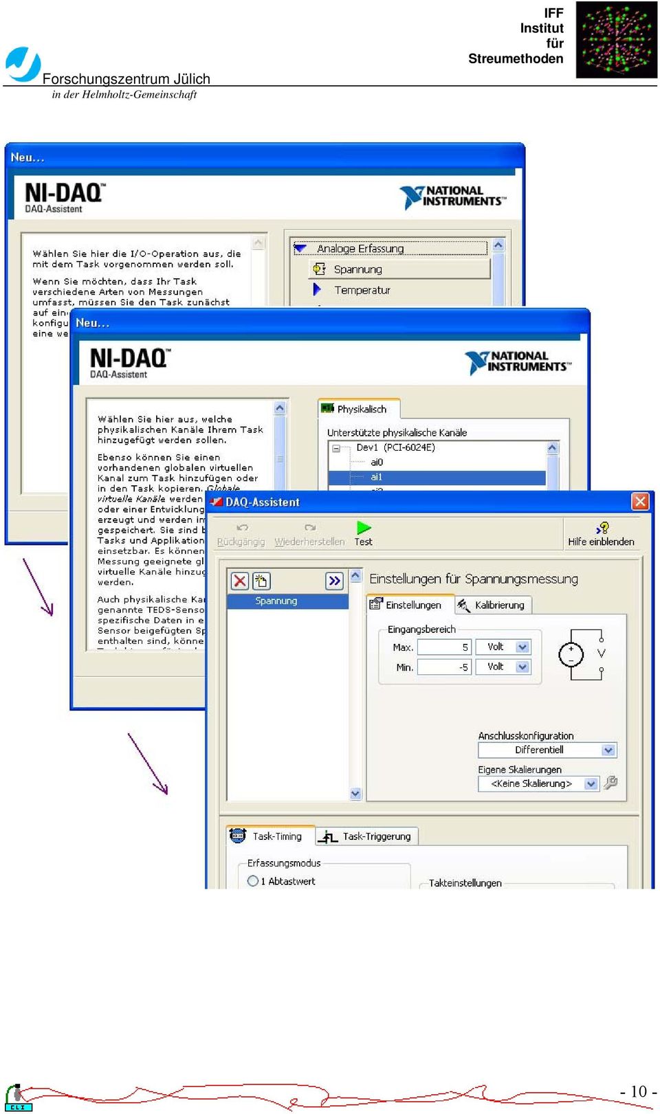
15 Connect a Voltage source onto the DAQ board (analog input) The LabVIEW graphical dataflow language and block diagram approach naturally represent the flow of your data and intuitively map user interface controls to your data, so you can easily view and modify your data or control inputs. For experienced programmers, LabVIEW delivers the performance, flexibility, and compatibility of a traditional programming language such as C or BASIC. In fact, the full-featured LabVIEW programming language has the same

16 constructs that traditional languages have -- variables, data types, looping, and sequencing structures as well as error handling. 3.3 Application Acquire Data from a Data Acquisition Device Communicate with and Control an Instrument Acquire Data from a Sensor Process and Analyze Measurement Data Design a Graphical User Interface Save Measurement Data to File And also Use LabVIEW with Other Software Applications Chapter 4 System Set-up 4.1 List of equipments - Power Supply (±15V) Typ: MADS A.-Nr.: U in: 115/*230V +10/-15% Hz I in Max.: 0.8/0.4A KNIEL System-Electronic GmbH D Karlsruhe/Germany IS: SC2000 Scan Controller Board GSI Lumonics IS: X and Y Optical Scanners GSI Lumonics VM-500 C

17 Patent Pending IS: / MiniSAX (Miniature Single AXis) GSI Lumonics Billerica, MA USA Model Mumber: IS: / Laser beam Laser radiation avoid exposure to beam class 3B laser product Iop: 1450mA Power: 75mW A-A Laser protect glasses Laser 2000 GmbH- TÜV ISO 9001 zert. Laserschutzbrille Modell 426 BOL Wareneingang: Laser radiation class 2 (for safty) - 1 Power Supply cable - 2 Startup SAX Interface Cables, part# Enable Interlock SAX Interface Cables - 2 Dual Axis Digital Servo Interface Cables - 1 RS-232 Computer Interface Cable, part# Sync/Cal Ribbon Cable - Host Computer - CD of GSI Lumonics CD-ROM SC2000 CLI CD of LabVIEW

18 4.2 Optical Scanners(VM500C) The VM500C Optical Scanner is member of the GSI Lumonics High Performance VM family of Galvanometers. It s designed for advanced beam and image positioning, and offer high dynamic performance along with high accuracy and instrument grade performance. The VM Series scanners use moving-magnet design together with the newly patented capacitive position detector that offers superior accuracy. The moving magnet technology maintains the low inertia, high rigidity and low temperature characteristics of the M series predecessors, while allowing for increased bandwidth. This enables the scanner to move at higher speeds with more precise angular positioning. The VM Series Scanners are optimized for both large and small signal applications, and provide improved drift, noise, and linearity. Highest performance is achieved when the VM Galvanometer is mated with GSI Lumonics newly designed mirror assemblies and an optimized GSI servo controller. When the thermal control option is purchased with the complimenting servo driver, the built-in thermal blanket around the position detector that is a standard

19 feature of all VM Series Galvanometers can be used to maintain a specific temperature, in order to eliminate temperature-related drift. Using the thermal control option of the VM series scanners minimizes scanner offset and gain drift. The set point for temperature-regulated scanners must be above the highest expected ambient temperature but not above 50º C. For maximum stability, temperature controlled scanners may require thermal isolation from the scanner mount so that heat sinking by the mount does not interfere with temperature regulation. Standard Mirrors (clear aperture) Maximum Scan Angle* VM500 4mm ±30º Optical 5mm ±25º Optical 6mm ±20º Optical

20

21 Mini SAX The MiniSAX (Miniature Single AXis) servo controller is one of GSI Lumonics most recent developments in galvanometric servo control technology. By taking advantage of the newest surface mount components, the MiniSAX provides full-function scan electronics at a size and cost less than many stripped down servo amplifiers. Advanced servo filtering techniques together with a low-coupling design provide extended bandwidths and improved response times. The MiniSAX was engineered with system designers in mind, incorporating a simple yet comprehensive and flexible interface structure. For the first time, laser system manufactures can purchase a truly high performance, cost effective galvanometer servo controller that allows convenient, in-head packaging. The MiniSAX uses a modular design, providing the ability to readily configure the driver for specific applications. An optional filter module is available in a variety of adjustable notch frequency ranges. The frequency response of this module can be optimized to handle a variety of customer-supplied loads. A thermal control module is available to support GSIL s thermally regulated scanners, allowing use of the industry s lowest drift galvanometers. The MiniSAX product line includes a variety of accessories that ease the integration into your manufacturing process. The MiniSAX mounting bracket provides convenient mounting surfaces and mates with either of two optional heatsinks. A test interface board allows easy access to a variety of important test points. Mating connectors and inexpensive assembly tools are available directly from GSI Lumonics. The MiniSAX Startup Kit is recommended for first time users and includes many of these valuable accessories
22 Command Input Characteristics Differential Voltage Range ±3 volts differential for full scale Input Impedance 5 KΩ differential Position Output ±3 volts differential for full scale Power Input Voltage ±15 to ±24 volts DC Quiescent Current +170mA, -150mA (servo enabled, galvo resting w/o error, no thermal controller) Motor Drive Power Dynamic Current max. 2.5 Amps RMS Peak Current 10.0 Amps Note: U20/U21 mounting screws should be tightened to a torque of 16 in-lb (1.8 N-M). Control I/O Characteristics Servo Ready Open Drain, Active Low (50 ma max.) Servo Enable TTL/CMOS Compatible, Active Low Temp OK * Open Drain, Active Low (50 ma max.) * Part of optional Temperature Controller Module Protection Fully Fused Motor Output, Automatic Gain Control, and Thermal Controller 1 Automatic Shutoff Over-position, Supply Undervoltage, Position Detector Inactive Temperature Range 0 C to 50 C Operating Size W x L x H
23 (not including mounting bracket) 2 1 x 3 3 x (54.5mm x 86.5mm x 31.35mm) Weight 66 grams (Includes all optional modules. Does not include mounting bracket)
24 - 20 -
25 4.4 GSI Lumonics SC2000 Digital Scan Controller The SC2000 Scan Controller is designed to provide fast, accurate, user-friendly control over GSI Lumonics MiniSAX and Dual Axis Digital servo amplifiers and associated peripherals. Using either the provided GSI Lumonics Command line interface software, or similar user-designed software, the controller can be programmed to operate in conjunction with a host computer or in a stand-alone configuration. The stand-alone configuration allows the user to run a series of programs, from non-volatile memory upon system power up, as well as trigger program execution using control input and output signals. Interfacing with a host computer, on the other hand, allows the user to choose a mode of operation, between the controller and the host, ranging from totally autonomous to tightly coupled. The Scan Controller interfaces directly to the position command, position feedback, and binary communications of the servo amplifiers. This allows for full position control of the system and control of the enable/status interlock between the SC2000 and driver board. Likewise, this interface allows the user to monitor position feedback from the galvo, as well as read calibration information digitally via the host computer. In addition to controlling the servos, the Scan Controller has hooks to aid in the interface and control of other peripherals typically associated with scanning systems. These include sync inputs and outputs, a pixel clock system, a calibration/data capture system, and other functionality available to volume OEM system designers
26 - 22 -
27 4.5 About Laser Class 2: Low risk to eyes. No risk to skin Class 2 laser products are defined as those emitting visible light for which the natural aversion response to bright light (including the blink reflex) prevents retinal injury, including direct viewing of the laser beam with optics that could concentrate the laser output into the eye. These lasers do, however, present a dazzle hazard. Lasers that were Class 2 under the previous version of remain Class 2 under the new scheme* Warning label: DO NOT STARE INTO BEAM Only use Class 2 for safety during the experiments in room. Class 3B Medium risk to eyes. Low risk to skin Class 3B laser products are defined as those for which direct exposure of the eye is hazardous, even taking aversion responses into account, but scattered laser light is usually safe. The higher power Class 3B lasers are also a skin hazard, but the natural aversion response to localised heating generally prevents a skin burn. Lasers that were Class 3B under the previous version of but which operate at a wavelength in the range to 4 µm and have output beams that are either high divergence or large diameter may qualify. Warning label: AVOID EXPOSURE TO THE BEAM
28 4.6 Hooking up the system Step 1 Before you begin: Be sure power supply is turned off Be sure make all connections firmly. Loose connections may cause communications and/or performance problems Be sure wearing a properly grounded wrist strap or heel strap. Components on the SC2000 Controller board are highly sensitive to electrostatic discharge. Step 2 Connecting the Power Supply: Using the provided power cable, connect the stripped leads to the power supply terminals as labeled: +15V to the positive supply terminal COM to the common terminal -15V to the negative supply terminal
29 Plug the power cable s Molex connector into the pwr connector, J2, on the SC2000 controller board. Step 3 Connecting the servo Interface Cables: For the MiniSAX servo amplifier: Using a Startup SAX Interface Cable (part numbered ), connect the X axis interface (J3) on the SC2000 to the X axis MiniSAX command interface (J2 on the SAX board)
30 Use the remaining Startup Interface Cable to connect the Y Axis interface (J8) on the SC2000 to the Y axis MiniSAX command interface (J2 on the SAX Board). Connect the X axis controller command interface, J3 on the SC2000, to the X axis servo command interface (J3 on the underside of the Digital Servo). Use the remaining command cable to connect the Y axis command interface, J8 on the SC2000 to the Y axis servo command interface (J4 on the underside of the of the Digital Servo). Step 4 Connecting the Host Computer: Connect the provided Computer Interface Cable (part number ) to an available serial port on your host computer. Remember which serial port you use since you will need to know which port to address when communicating with the controller board. Connect the other end of the cable to the Serial Interface connector (J1) on the controller board. Step 5 Sync/Cal Connections (Optional): The Sync/Cal connector provides access to the synchronization/calibration I/O as well as the pixel clock output of the Scan Controller. Figure 3 shows a system using one of the (open drain) sync outputs and the auxiliary +5V output to power and control a diode laser module. For further information on the Sync/Cal and pixel clock features of the scan controller, read the GSI Lumonics Scan Controller Users Manual. For controlling a low power laser diode module: Connect laser diode (+) output to +5V output (J2, pin 1) of the Scan Controller Connect laser diode (-) output to sync gnd (J4, pin 5) on the Scan Controller Connect laser diode modulation control output to sync 1 (J4, pin 1) on the Scan Controller. Note: User must supply a 4.7k pull up resistor between the +5V and Sync
31 There are other ways to interface to a laser. For instance connect the + lead to +5V and the lead to the sync pin. This would be good enough for users who don t need high performance switching. Warning: Check the manufacturer s voltage and current specifications before hooking up a laser diode or any other peripheral. The open drain outputs on the Scan Controller (sync 1 4) are specified to sink up to 100mA continuous, and withstand peaks up to 40 V. These output must be clamped if inductive loads are to be driven (i.e. a small relay). Otherwise, the voltage transient generated at turn-off can destroy the sync output transistors
32 - 28 -
33 Step 6 Software Installation: The GSI Lumonics Command Line Interface software discussed in the manual can be found on the provided CD-ROM. Read the ReadMe.txt file for the latest information and changes. To install the software run <CDROM> :\install\disc 1\setup.exe. The setup program will create a default installation directory (typically C:\GSI), install the application and support files and peripheral tools, create a program group and add an item in the Windows start menu. Step 7 Final Setup: If using a Servo/Galvo pair, connect galvo to driver board. Double check all connections to make sure they are correct and secure Chapter 5 GSI Lumonics SC2000 support Program 5.1 Introduction of GSI Group
34 With corporate offices in Billerica, MA, GSI Group develops and delivers the enabling technology solutions that bring customers' advanced manufacturing applications to life. Their leading brands include precision motion products, lasers, and laser systems, and are used to boost efficiency and productivity in the global medical, semiconductor, electronics, and industrial markets. 5.2 Introduction of the Support Program The Command Line Interface software allows users to communicate with the Scan Controller quickly and easily. It is intended primarily as an environment for designing and programming stand-alone applications, and for system evaluation. Using Command Line Interface software during system evaluation provides a user-friendly learning environment in which functional capabilities of the Scan Controller can be understood and applied. Once the functionality and limitations of the Scan Controller are understood, designing host-based, realtime system programs becomes much easier. While pieces of the provided code can be utilized in host-based, real-time systems, that is not its primary intent. When you start to run the CLI.exe,it will automatically raise the Serial Port selector sub-window asking you to set the serial port device for Scan Controller communication. Choose one COM that was used and press Done to enter your serial port
35 - 31 -
36 Here is the main Functions of the Command Line Interface Main Window:
37 - 33 -
38 5.3 Command Reference The Command Line Interface (CLI) and the Motion Assembler Component (MAC) incorporate assemblers that translate English language program commands into the binary language of the SC2000. Each command in defined in the assembly language context and then in the binary context, but note that the SC2000 will only accept commands uploaded in the binary format. In order to exert the program efficiently we need to familiar with the Commands of the program especially these in boldfaced that will be used in the project.?freeflashspace : Returns byte count of available flash memory.?freeramspace : Returns byte count of available SRAM.?ID : Return system revision information.?opticalcal?position : Return the current position on the given axis.?status : Returns error information and clears error state.?sync?temp?tempok AbortPgm : Halts the currently running program and disables servos. ComConfig : Configure RS-232 serial port parameters for communication. CreateFlashPgm : The action of Create Flash Program is to initiate the storage mechanism in the Scan Controller so that a program may be saved to non-volatile memory on-board the Scan Controller. CreatePgm : Store a Scan Controller program in volatile memory on-board the Scan Controller. DelayedLaserGate DelayedSetFPS
39 DelayedSetOutputSignal DelayedSetSync DelayedUnSetSync DeltaPosition : Set the position of the current axis relative to the currentposition. DeltaPositionXY : Set the vector position relative to the current position. DeltaSlew : Move smoothly on the current axis relative to the currentposition. DeltaSlewXY : Move smoothly relative to the current vectorposition. DeltaTweakAxis : Apply gain and offset deltas to subsequent raster operations. DeltaTweakAxisXY : Apply gain and offset deltas to subsequent vector operations. Disable Enable End : Marks the end of a Scan Controller program. ExecutePgm : Commence the execution of the named program. ExecuteRasterPgm ExecBinPgm ExecSerialNumber ExitPgm : Use ExitPgm to terminate programs by having them fall through repeat and waitsync [1-4] statements. FlipExchangeAxis : Use FlipExchangeAxis to reverse the sense of one or both axis and to interchange the command stream between X and Y. Ifexecutepgm Ifexecuterasterpgm Iftempokexecutepgm Iftempokexecuterasterpgm LaserGate LaserModeSetup
40 Nrepeat PackMemory Position : Set the absolute position of the current axis. PositionXY : Set the absolute vector position. Raster : Declare the target axis for subsequent single axis (raster) commands and place the Scan Controller in raster mode. ReleasePgm Repeat : The Repeat command will cause the Scan Controller program flow to return to the first instruction in the program where execution is repeated. SaveConfigInFlash SerialNumberSetup SetAnalogOutput SetConfigVar SetFPS SetGSS SetLaserPower SetMOFGains SetMOFMode SetMOFShift SetOutputSignal SetPWM SetSetSyncDelay SetSync SetTicklePulses SetUnsetSyncDelay SetXPRGain
41 SetXPROffset SetYPRGain SetYPROffset Slew : Move smoothly to the given absolute position on the current axis in the specified number of tick counts. SlewXY : Move smoothly to the given absolute vector position in the specified number of tick counts. TransformAxis : Apply rotation or skew transformation to vector motion commands. TweakAxis : Apply gain and offset to subsequent axis operations. TweakAxisXY : Apply gain and offset to subsequent vector operations. UnSetSync Vector : Place the Scan Controller in vector mode. Wait : Pause execution for the given number of tick counts. WaitMOFDistance WaitPosition : Pause Scan Controller program execution until the commanded position for the current axis is reached. WaitPositionXY : Pause Scan Controller program execution until the commanded position is reached. WaitSync Explanation of Operational Modes Overview: There are various modes of operation that overlap or are mutually exclusive depending upon those compared. Raster Mode: A fundamental operating mode for either programs or immediate instructions in which all motion commands are directed to a specified axis
DMX-K-DRV. Integrated Step Motor Driver + (Basic Controller) Manual
 Manual") DMX-K-DRV Integrated Step Motor Driver + (Basic Controller) Manual DMX-K-DRV Manual page 1 rev 1.33 COPYRIGHT 2007 ARCUS, ALL RIGHTS RESERVED First edition, June 2007 ARCUS TECHNOLOGY copyrights this document.
DMX-K-DRV Integrated Step Motor Driver + (Basic Controller) Manual DMX-K-DRV Manual page 1 rev 1.33 COPYRIGHT 2007 ARCUS, ALL RIGHTS RESERVED First edition, June 2007 ARCUS TECHNOLOGY copyrights this document.
Transmitter Interface Program
 Transmitter Interface Program Operational Manual Version 3.0.4 1 Overview The transmitter interface software allows you to adjust configuration settings of your Max solid state transmitters. The following
Lab 3: Introduction to Data Acquisition Cards
 Lab 3: Introduction to Data Acquisition Cards INTRODUCTION: In this lab, you will be building a VI to display the input measured on a channel. However, within your own VI you will use LabVIEW supplied
Building a Simulink model for real-time analysis V1.15.00. Copyright g.tec medical engineering GmbH
 g.tec medical engineering GmbH Sierningstrasse 14, A-4521 Schiedlberg Austria - Europe Tel.: (43)-7251-22240-0 Fax: (43)-7251-22240-39 office@gtec.at, http://www.gtec.at Building a Simulink model for real-time
OWNERS MANUAL. WattsVIEW. Power Monitor Model: DC-10000. http://wattsview.com. WattsVIEWTM. Models: DC-10000 Serial DC-1000 USB DC-25000
 WattsVIEW Power Monitor Model: DC-10000 DC Power Monitoring Made Easy Models: DC-10000 Serial DC-1000 USB DC-25000 OWNERS MANUAL PAGE 1 of 23 Table of Contents WattsVIEW Power Monitor Model: DC-10000...1
THERMAL ANEMOMETRY ELECTRONICS, SOFTWARE AND ACCESSORIES
 TSI and TSI logo are registered trademarks of TSI Incorporated. SmartTune is a trademark of TSI Incorporated. THERMAL ANEMOMETRY ELECTRONICS, SOFTWARE AND ACCESSORIES IFA 300 Constant Temperature Anemometry
SA-9600 Surface Area Software Manual
 SA-9600 Surface Area Software Manual Version 4.0 Introduction The operation and data Presentation of the SA-9600 Surface Area analyzer is performed using a Microsoft Windows based software package. The
Measuring Temperature withthermistors a Tutorial David Potter
 NATIONAL INSTRUMENTS The Software is the Instrument Application Note 065 Measuring Temperature withthermistors a Tutorial David Potter Introduction Thermistors are thermally sensitive resistors used in
Sierra S-Series Smart Interface Software User Manual
 Sierra S-Series Smart Interface Software User Manual Part Number IM-SIP 08/99 Revision B 5 Harris Court, Building L Monterey, CA 93940 (831) 373-0200 (800) 866-0200 Fax (831) 373-4402 http://www.sierrainstruments.com
Computer Controlled Generating Stations Control and Regulation Simulator, with SCADA SCE
 Technical Teaching Equipment Computer Controlled Generating Stations Control and Regulation Simulator, with SCADA SCE EDIBON SCADA System Teaching Technique used 4 5 2 Data Acquisition Board Cables and
* DISCLAIMER: Contents. How to Use This Guide: COMMERCIAL INSTALL GUIDE 2
 COMMERCIAL INSTALL GUIDE 2 Contents How to Use This Guide: The first section of this guide is designed to assist you with the installation of your DECK Monitoring hardware. The revenue grade meter and
STIM202 Evaluation Kit
 Table of contents: 1 FEATURES... 2 2 GENERAL DESCRIPTIONS AND SYSTEM CONTENTS... 2 3 SYSTEM REQUIREMENTS... 2 4 GETTING STARTED... 3 4.1 INSTALLATION OF NI-SERIAL CABLE ASSEMBLY DRIVER... 3 4.2 INSTALLATION
DeviceNet Bus Software Help for Programming an Allen Bradley Control System
 FBP FieldBusPlug V7 DeviceNet Bus Software Help for Programming an Allen Bradley Control System DeviceNet Software Help for Programming an Allen Bradley Control System Contents Page General Purpose...
Servo Motors (SensorDAQ only) Evaluation copy. Vernier Digital Control Unit (DCU) LabQuest or LabPro power supply
 Evaluation copy. Vernier Digital Control Unit (DCU) LabQuest or LabPro power supply") Servo Motors (SensorDAQ only) Project 7 Servos are small, relatively inexpensive motors known for their ability to provide a large torque or turning force. They draw current proportional to the mechanical
Servo Motors (SensorDAQ only) Project 7 Servos are small, relatively inexpensive motors known for their ability to provide a large torque or turning force. They draw current proportional to the mechanical
Application/Connection Examples
 This Quick Start Guide is designed to familiarize the user with the connection and configuration of the DTS-305 DIN rail mounted single / 3 phase power & energy meter with RS-485 or TCP communications.
SMART SENSOR COLLECTION
 TEMPERATURE SENSOR This sensor measures temperature in degrees Celsius or Fahrenheit. It works with all SensorHawk base units (SensorHawk-2, SensorHawk-8 and SensorHawk8/20) as well as the SecurityHawk-8
EasyC. Programming Tips
 EasyC Programming Tips PART 1: EASYC PROGRAMMING ENVIRONMENT The EasyC package is an integrated development environment for creating C Programs and loading them to run on the Vex Control System. Its Opening
Brake module AX5021. Documentation. Please read this document carefully before installing and commissioning the brake module!
 Documentation Brake module AX5021 Please read this document carefully before installing and commissioning the brake module! Version : 1.2 : 2012.03.05 Date Article-no. : TDmlAX-5021-0000-0200 Page 2/8
We bring quality to light. MAS 40 Mini-Array Spectrometer. light measurement
 MAS 40 Mini-Array Spectrometer light measurement Features at a glance Cost-effective and robust CCD spectrometer technology Standard USB interface Compatible with all Instrument Systems measuring adapters
PhidgetInterfaceKit 8/8/8
 PhidgetInterfaceKit 8/8/8 Operating Systems: Windows 2000/XP/Vista, Windows CE, Linux, and Mac OS X Application Programming Interfaces (APIs): Visual Basic, VB.NET, C, C++, C#, Flash 9, Flex, Java, LabVIEW,
USB-500/600 Series Low-Cost Data Loggers and Accessories
 Low-Cost Data Loggers and Accessories Features Stand-alone, remote data loggers and portable logger assistant Measure temperature, humidity, voltage, current, or event/state change 1 or 2 channels Low
CAUTION! THE 7I29 USES VOLTAGE AND POWER LEVELS THAT REPRESENT A HAZARD TO LIFE AND LIMB.
 7I29 MANUAL Rev 1.5 CAUTION! THE 7I29 USES VOLTAGE AND POWER LEVELS THAT REPRESENT A HAZARD TO LIFE AND LIMB. THE 7I29 IS INTENDED FOR USE BY OEMS THAT WILL INTEGRATE IT INTO A SYSTEM WITH INTERLOCKS AND
Laserlyte-Flex Alignment System
 Laserlyte-Flex Alignment System LaserLyte-Flex The LaserLyte-Flex Alignment System is a unique, interchangeable, low cost plug and play laser system. Designed specifically for aligning and positioning
T-BOXN12R. First steps with T-BOXN12R. You can make it wireless. Date: 2004-07-16 Version 1.0
 T-BOXN12R You can make it wireless First steps with T-BOXN12R Date: 2004-07-16 Version 1.0 Content 1. Purpose of this document... 3 2. T-BoxN12R overview... 4 3. First step... 5 3.1. Preparing your workshop
MANUAL FOR RX700 LR and NR
 MANUAL FOR RX700 LR and NR 2013, November 11 Revision/ updates Date, updates, and person Revision 1.2 03-12-2013, By Patrick M Affected pages, ETC ALL Content Revision/ updates... 1 Preface... 2 Technical
Automation System TROVIS 6400 TROVIS 6493 Compact Controller
 Automation System TROVIS 6400 TROVIS 6493 Compact Controller For panel mounting (front frame 48 x 96 mm/1.89 x 3.78 inch) Application Digital controller to automate industrial and process plants for general
Laser diffuse reflection light scanner with background suppression. Dimensioned drawing
 Specifications and description HRTL 3B Laser diffuse reflection light scanner with background suppression Dimensioned drawing We reserve the right to make changes DS_HRTL3B_en.fm en 01-2010/12 50114049
High Power Programmable DC Power Supplies PVS Series
 Data Sheet High Power Programmable DC Power Supplies The PVS10005, PVS60085, and PVS60085MR programmable DC power supplies offer clean output power up to 5.1 kw, excellent regulation, and fast transient
RL HW / RL HW+ / RL HGW / RL HV / RL HVPW/RL HVPW-G
 Auto-Levelling Rotary Laser Level RL HW / RL HW+ / RL HGW / RL HV / RL HVPW/RL HVPW-G 77-496 / 77-429 / 77-439 / 77-497 / 77-427/ 77-441 Please read these instructions before operating the product Auto-Levelling
4.1 DESCRIPTION OF CONTROLS cont.
 4.1 DESCRIPTION OF CONTROLS cont. EGPS-1022 Power Supply Remote Control Computer Panel (ADDITIONAL CONTROLS AND INDICATORS BELOW MAIN PANEL) Fig. 4.1-4 Screen captures of LabVIEW TM program for EGPS-1022
Advantages of digital servo amplifiers for control of a galvanometer based optical scanning system
 Advantages of digital servo amplifiers for control of a galvanometer based optical scanning system D.A. Sabo SCANLAB America Inc. 11427 Reed Hartman Highway Cincinnati, Ohio 45241 Andreas Engelmayer SCANLAB
Capacitive Touch Lab. Renesas Capacitive Touch Lab R8C/36T-A Family
 Renesas Capacitive Touch Lab R8C/36T-A Family Description: This lab will cover the Renesas Touch Solution for embedded capacitive touch systems. This lab will demonstrate how to setup and run a simple
Technical Datasheet Scalar Network Analyzer Model 8003-10 MHz to 40 GHz
 Technical Datasheet Scalar Network Analyzer Model 8003-10 MHz to 40 GHz The Giga-tronics Model 8003 Precision Scalar Network Analyzer combines a 90 db wide dynamic range with the accuracy and linearity
Lab 4 - Data Acquisition
 Spring 11 Lab 4 - Data Acquisition Lab 4-1 Lab 4 - Data Acquisition Format This lab will be conducted during your regularly scheduled lab time in a group format. Each student is responsible for learning
TRIMBLE TX5 3D LASER SCANNER QUICK START GUIDE
 TRIMBLE TX5 3D LASER SCANNER QUICK START GUIDE Equipment 1 8 9 5 6 7 4 3 2 The TX5 laser scanner ships with the following equipment: 1 Scanner transport and carry case 6 USB memory card reader 2 AC power
JNIOR. Overview. Get Connected. Get Results. JNIOR Model 310. JNIOR Model 312. JNIOR Model 314. JNIOR Model 410
 The INTEG is an Ethernet I/O (digital, analog) device that monitors and controls a small set of process signals. functions as both basic I/O for integration with another application or system AND as a
USB-AD16f Data acquisition system (USB)
") Data acquisition system (USB) Measurement & Control. Extremely powerful. Precisely record and output signals with the USB-AD16f: The high-performance USB data acquisition system accomodated in a stable
Data acquisition system (USB) Measurement & Control. Extremely powerful. Precisely record and output signals with the USB-AD16f: The high-performance USB data acquisition system accomodated in a stable
R&S ZVA-Z75, -Z110, -Z140, -Z170, -Z220, -Z325, -Z500 Converters Quick Start Guide
 R&S ZVA-Z75, -Z110, -Z140, -Z170, -Z220, -Z325, -Z500 Converters Quick Start Guide (=7ÔWÌ) 1307.7039.62 06 Test & Measurement Quick Start Guide This Quick Start Guide describes the following converter
LED red (-): Measuring value < lower tolerance threshold LED red (+): Measuring value > upper tolerance threshold. Page 1/6
: Measuring value < lower tolerance threshold LED red (+): Measuring value > upper tolerance threshold. Page 1/6") L-LAS Series L-LAS-LT-165-CL - Line laser 1 mw, laser class 2 - Visible laser line (red light 670 nm), typ. 2 mm x 3 mm - Reference distance approx. 165 mm - Measuring range typ. 65... 265 mm - Resolution
L-LAS Series L-LAS-LT-165-CL - Line laser 1 mw, laser class 2 - Visible laser line (red light 670 nm), typ. 2 mm x 3 mm - Reference distance approx. 165 mm - Measuring range typ. 65... 265 mm - Resolution
Current Monitoring Kit QUICK START GUIDE
 Current Monitoring Kit QUICK START GUIDE Pico Technology EL040 Current Monitoring Kit Quick Start Guide CONTENTS 1 Introduction... 1 2 Kit contents... 3 3 Installation... 3 3.1 Connecting the system together...
MINIMAT-EC-Servo Screwdriver Spindles
 Screwdriving technology Automation Air motors Air tools Screwdriver Spindles electric MINIMAT-EC-Servo Screwdriver Spindles Maximum Flexibility and process Control Straight Spindle Form - Torque range
Current Monitoring Kit
 Current Monitoring Kit QUICK START GUIDE DO090-6 CONTENTS Issues: 1) 2.10.02 WP A4 format 2) 2.10.02 Added safety warning 3) 17.3.06 Word A5 format. S1: Removed relay modules. S2: Added MI010. S4.1: added
FTDI VCP DRIVER (free) (WIN/MAC/LINUX) http://www.ftdichip.com/drivers/vcp.htm
 (WIN/MAC/LINUX) http://www.ftdichip.com/drivers/vcp.htm") 002 - CONNECTING THE PRINTER Now that you have an idea what 3D printing entails, we can continue and connect the printer to your computer. First make sure you have a computer with a decent amount of RAM
002 - CONNECTING THE PRINTER Now that you have an idea what 3D printing entails, we can continue and connect the printer to your computer. First make sure you have a computer with a decent amount of RAM
FREQUENCY RESPONSE ANALYZERS
 FREQUENCY RESPONSE ANALYZERS Dynamic Response Analyzers Servo analyzers When you need to stabilize feedback loops to measure hardware characteristics to measure system response BAFCO, INC. 717 Mearns Road
1.44 kw Programmable DC Power Supplies XLN Series
 Data sheet 1.44 kw Programmable DC Power Supplies XLN Series New Family of High Density System Power Supplies The B&K Precision XLN series are compact, programmable, single-output DC power supplies, suitable
DDX 7000 & 8003. Digital Partial Discharge Detectors FEATURES APPLICATIONS
 DDX 7000 & 8003 Digital Partial Discharge Detectors The HAEFELY HIPOTRONICS DDX Digital Partial Discharge Detector offers the high accuracy and flexibility of digital technology, plus the real-time display
User's Guide. Integrating Sound Level Datalogger. Model 407780. Introduction
 User's Guide 99 Washington Street Melrose, MA 02176 Phone 781-665-1400 Toll Free 1-800-517-8431 Visit us at www.testequipmentdepot.com Back to the Extech 407780 Product Page Integrating Sound Level Datalogger
EDI Distributor Control Interface Wiring and Setup Instructions
 Universal I/O EDI Distributor Control Interface Wiring and Setup Instructions EDI UNIVERSAL I/O INTERFACE MODULE The only interface needed for EDI-V5 controls Network compatible with all older EDI controls
Alignment Laser System.
 - O T 6 0 0 0 Alignment Laser System. The OT-6000. Multi -Target,Two Dimensional Alignment. Introducing the most powerful way to measure alignment at distances up to 300 feet. The OT-6000 Alignment Laser
USER MANUAL V5.0 ST100
 GPS Vehicle Tracker USER MANUAL V5.0 ST100 Updated on 15 September 2009-1 - Contents 1 Product Overview 3 2 For Your Safety 3 3 ST100 Parameters 3 4 Getting Started 4 4.1 Hardware and Accessories 4 4.2
SL Series AC and DC Electronic Loads
 SL Series AC and DC Electronic Loads Applications AC & DC Power Supply Testing Rechargeable batteries and chargers Fuel cell test - cells and stacks PFC circuit test Pulsed LED Test and Burn-in Laser Diode
PoNET kbd48cnc. User s manual
 PoNET kbd48cnc User s manual Version: 16/10/2012 SAFETY INFORMATION! This product is intended for integration by the user into a computer numerical control (CNC) machine. It is the user's responsibility
Configure Inverter output for two utility settings, (1)120V/60Hz, (2)220V/50Hz
120V/60Hz, (2)220V/50Hz") HV Solar Inverter System GUI Overview January 2012 TMS320C2000 Systems Applications Collateral The HV Solar Inverter System GUI provides a simple interface to evaluate some of the functionalities of the
HV Solar Inverter System GUI Overview January 2012 TMS320C2000 Systems Applications Collateral The HV Solar Inverter System GUI provides a simple interface to evaluate some of the functionalities of the
Three Channel Optical Incremental Encoder Modules Technical Data
 Three Channel Optical Incremental Encoder Modules Technical Data HEDS-9040 HEDS-9140 Features Two Channel Quadrature Output with Index Pulse Resolution Up to 2000 CPR Counts Per Revolution Low Cost Easy
1. SAFETY INFORMATION
 RS-232 Sound Level Meter 72-860A INSTRUCTION MANUAL www.tenma.com 1. SAFETY INFORMATION Read the following safety information carefully before attempting to operate or service the meter. Use the meter
MCR1900 Media Converter 19-Slot Chassis
 MCR1900 Media Converter 19-Slot Chassis Installation Guide Part #5500304-11 Copyright Statement This document must not be reproduced in any way whatsoever, either printed or electronically, without the
Analog Servo Drive 25A8
 Description Power Range NOTE: This product has been replaced by the AxCent family of servo drives. Please visit our website at www.a-m-c.com or contact us for replacement model information and retrofit
Bluetooth + USB 16 Servo Controller [RKI-1005 & RKI-1205]
![Bluetooth + USB 16 Servo Controller [RKI-1005 & RKI-1205]](/thumbs/40/21161302.jpg "Bluetooth + USB 16 Servo Controller [RKI-1005 & RKI-1205]") Bluetooth + USB 16 Servo Controller [RKI-1005 & RKI-1205] Users Manual Robokits India info@robokits.co.in http://www.robokitsworld.com Page 1 Bluetooth + USB 16 Servo Controller is used to control up to
Bluetooth + USB 16 Servo Controller [RKI-1005 & RKI-1205] Users Manual Robokits India info@robokits.co.in http://www.robokitsworld.com Page 1 Bluetooth + USB 16 Servo Controller is used to control up to
SuperIOr Controller. Digital Dynamics, Inc., 2014 All Rights Reserved. Patent Pending. Rev: 5-16-14 1
 SuperIOr Controller The SuperIOr Controller is a game changer in the world of high speed embedded control. The system combines incredible speed of both control and communication with revolutionary configurable
Animated Lighting Software Overview
 Animated Lighting Software Revision 1.0 August 29, 2003 Table of Contents SOFTWARE OVERVIEW 1) Dasher Pro and Animation Director overviews 2) Installing the software 3) Help 4) Configuring the software
Disturbance Recoder SPCR 8C27. Product Guide
 Issued: April 1999 Status: Updated Version: C/26.04.2006 Data subject to change without notice Features Versatile digital disturbance recorder module for recording various phenomena in the electric power
The software beyond the climatic. Environment simulation
 Spirale 2 The software beyond the climatic Environment simulation Spirale 2... Take it easy! Spirale 2 is a new software, based on a reliable system (Windows NT) and if its performances are surprising,
M68EVB908QL4 Development Board for Motorola MC68HC908QL4
 M68EVB908QL4 Development Board for Motorola MC68HC908QL4! Axiom Manufacturing 2813 Industrial Lane Garland, TX 75041 Email: Sales@axman.com Web: http://www.axman.com! CONTENTS CAUTIONARY NOTES...3 TERMINOLOGY...3
Isolated AC Sine Wave Input 3B42 / 3B43 / 3B44 FEATURES APPLICATIONS PRODUCT OVERVIEW FUNCTIONAL BLOCK DIAGRAM
 Isolated AC Sine Wave Input 3B42 / 3B43 / 3B44 FEATURES AC averaging technique used to rectify, amplify, and filter 50 Hz to 400 Hz sine-wave signals. Accepts inputs of between 20 mv to 550 V rms to give
In-System Programmer USER MANUAL RN-ISP-UM RN-WIFLYCR-UM-.01. www.rovingnetworks.com 1
 RN-WIFLYCR-UM-.01 RN-ISP-UM In-System Programmer 2012 Roving Networks. All rights reserved. Version 1.1 1/19/2012 USER MANUAL www.rovingnetworks.com 1 OVERVIEW You use Roving Networks In-System-Programmer
AXIS 291 1U Video Server Rack Installation Guide
 AXIS 291 1U Video Server Rack Installation Guide About This Document This document describes how to install Axis blade video servers in the AXIS 291 1U Video Server Rack. Updated versions of this document
Six-servo Robot Arm. DAGU Hi-Tech Electronic Co., LTD www.arexx.com.cn. Six-servo Robot Arm
 Six-servo Robot Arm 1 1, Introduction 1.1, Function Briefing Servo robot, as the name suggests, is the six servo motor-driven robot arm. Since the arm has a few joints, we can imagine, our human arm, in
Ethernet. Customer Provided Equipment Configuring the Ethernet port.
 Installing the RDSP-3000A-NIST Master Clock. Ethernet Connect the RJ-45 connector to a TCP/IP network. Equipment The following equipment comes with the clock system: RDSP-3000A-NIST Master Clock Module.
Impedance 50 (75 connectors via adapters)
") VECTOR NETWORK ANALYZER PLANAR TR1300/1 DATA SHEET Frequency range: 300 khz to 1.3 GHz Measured parameters: S11, S21 Dynamic range of transmission measurement magnitude: 130 db Measurement time per point:
VECTOR NETWORK ANALYZER PLANAR TR1300/1 DATA SHEET Frequency range: 300 khz to 1.3 GHz Measured parameters: S11, S21 Dynamic range of transmission measurement magnitude: 130 db Measurement time per point:
ABB Drives. User s Manual HTL Encoder Interface FEN-31
 ABB Drives User s Manual HTL Encoder Interface FEN-31 HTL Encoder Interface FEN-31 User s Manual 3AUA0000031044 Rev B EN EFFECTIVE: 2010-04-06 2010 ABB Oy. All Rights Reserved. 5 Safety instructions
Cell Phone Vibration Experiment
 Objective Cell Phone Vibration Experiment Most cell phones are designed to vibrate. But at what frequency do they vibrate? With an accelerometer, data acquisition and signal analysis the vibration frequency
NETWORK ENABLED EQUIPMENT MONITOR
 NETWORK ENABLED EQUIPMENT MONITOR Remotely Monitor Sensors over the Internet Connect Sensors to the Web to Remotely Monitor Equipment, Processes or Other Applications A Complete, Easy to Deploy, Stand-Alone
Work with Arduino Hardware
 1 Work with Arduino Hardware Install Support for Arduino Hardware on page 1-2 Open Block Libraries for Arduino Hardware on page 1-9 Run Model on Arduino Hardware on page 1-12 Tune and Monitor Models Running
HERZ-Thermal Actuators
 HERZ-Thermal Actuators Data Sheet 7708-7990, Issue 1011 Dimensions in mm 1 7710 00 1 7710 01 1 7711 18 1 7710 80 1 7710 81 1 7711 80 1 7711 81 1 7990 00 1 7980 00 1 7708 11 1 7708 10 1 7708 23 1 7709 01
Key Features. Product Overview. Threaded Joint Rate Simulator
 Key Features 4 A threaded fastener and nut 4 Fully automated quick release of fastener 4 Fully automated variable joint rate from soft to hard 4 Tool testing in accordance with VDI/VDE2647 4 Torque or
Multi-Range Programmable DC Power Supplies 9115 Series
 Data Sheet 1200 W Multi-Range DC Power Supplies Features & Benefits Any 9115 series model can replace several supplies on your bench or in your rack. Unlike conventional supplies with fixed output ratings,
Industrial Bar Code Scanners
 DS4800 Industrial Bar Code Scanners Enhanced Connectivity Ease of use Configuration SW Tool ACR4 technology Smart focus adjustment APPLICATIONS Automated warehousing Reading on pallets Picking systems
Research-Grade Research-Grade. Capture
 Research-Grade Research-Grade Motion Motion Capture Capture The System of Choice For Resear systems have earned the reputation as the gold standard for motion capture among research scientists. With unparalleled
For a complete explanation of all the functions and configurations available please refer to the SC6006: Manual of operation.
 PRELIMINARY TECHNICAL INFORMATION Three-phase Digital SCR Firing Board HIGHLIGHTS - Up to 480 V AC input supply voltage - Up to 700 V AC sync input - DSP controlled - Digital or analog input signaling
Whale 3. User Manual and Installation Guide. DC Servo drive. Contents. 1. Safety, policy and warranty. 1.1. Safety notes. 1.2. Policy. 1.3. Warranty.
 Whale 3 DC Servo drive User Manual and Installation Guide Contents 1. Safety, policy and warranty. 1.1. Safety notes. 1.2. Policy. 1.3. Warranty. 2. Electric specifications. 2.1.Operation ranges. 3. Connections
Cross-beam scanning system to detect slim objects. 100 mm 3.937 in
 891 Object Area Sensor General terms and conditions... F-17 Related Information Glossary of terms... P.1359~ Sensor selection guide...p.831~ General precautions... P.1405 PHOTO PHOTO Conforming to EMC
SE05: Getting Started with Cognex DataMan Bar Code Readers - Hands On Lab Werner Solution Expo April 8 & 9
 SE05: Getting Started with Cognex DataMan Bar Code Readers - Hands On Lab Werner Solution Expo April 8 & 9 Learning Goals: At the end of this lab, the student should have basic familiarity with the DataMan
IP Box Camera ACM-5711. Ver. 081016. Hardware User s Manual
 IP Box Camera ACM-5711 Ver. 081016 Hardware User s Manual 0 0 PRECAUTIONS 1. Read these instructions All the safety and operating instructions should be read before the product is operated. 2. Heed all
Polarization of Light
 Polarization of Light References Halliday/Resnick/Walker Fundamentals of Physics, Chapter 33, 7 th ed. Wiley 005 PASCO EX997A and EX999 guide sheets (written by Ann Hanks) weight Exercises and weights
PRODUCTIVITY THROUGH INNOVATION 600 CONTROL DIRECT DRIVE TECHNICAL/OPERATION MANUAL
 Rev. D PRODUCTIVITY THROUGH INNOVATION 600 CONTROL DIRECT DRIVE TECHNICAL/OPERATION MANUAL 10 BORIGHT AVENUE, KENILWORTH NEW JERSEY 07033 TELEPHONE: 800-524-0273 FAX: 908-686-9317 TABLE OF CONTENTS Page
High Performance Visible Laser Diode Scanners
 A B ALLEN-BRADLEY High Performance Visible Laser Diode Scanners (Catalog No. 27-LD4z1, -LD4z4 27-LD8z1, -LD8z4) Product Data These high performance, fixed-mount scanners use a Visible Laser Diode (VLD)
Electronic Control Devices The European Product Catalogue 2007
 FX14 Field Controller (1/4) FX14 Field Controller The FX14 is an equipment field controller in the Facility Explorer range of products. The controller is designed specifically for commercial Heating, Ventilating,
15 Series - Electronic step relay and dimmer. Features 15.91 15.51 15.81 SERIE
 Series - Electronic step relay and dimmer SERIE Features.91.51.81 Electronic step relay and dimmer for control of lighting levels Suitable for incandescent and halogen lighting loads (with or without transformer
Description. Dimensions. Features. www.pwb-encoders.com. precision works better
 Description The MEC22 is a high resolution optical hollow shaft encoder that can be fixed quickly and easily on different sizes of motor shafts. The encoder provides two square wave outputs in quadrature
BSE Geluid en Licht Pagina 1 van 5. Description
 Description The MiniMAC Profile is an automated moving-head spotlight that provides 12 dichroic color filters, 7 interchangeable rotating gobos, high-speed mechanical shutter, 540 of pan by 270 of tilt,
EVAL-UFDC-1/UFDC-1M-16
 Evaluation Board for Universal Frequency-to- Digital Converters UFDC-1 and UFDC-1M-16 EVAL-UFDC-1/UFDC-1M-16 FEATURES Full-Featured Evaluation Board for the Universal Frequency-to-Digital Converters UFDC-1
User Manual. Humidity-Temperature Chart Recorder. Model RH520
 User Manual Humidity-Temperature Chart Recorder Model RH520 Introduction Congratulations on your purchase of the Extech RH520 Temperature + Humidity Chart Recorder. The RH520 measures and displays Temperature,
Quick Installation. A Series of Intelligent Bar Code Reader with NeuroFuzzy Decoding. Quick Installation
 Quick Installation A Series of Intelligent Bar Code Reader with NeuroFuzzy Decoding This chapter intends to get your new FuzzyScan scanner working with your existing system within minutes. General instructions
EXPERTS IN WATER COOLING SINCE 2001. aquastream ULTIMATE SUPER SILENT PUMP TECHNOLOGY. The ultimate pump system. www.aqua-computer.
 The ultimate pump system www.aqua-computer.de AQUASTREAM Since its market introduction in 2003, the name stands for reliable and durable water cooling pump technology - made in Germany. We have bundled
AC-115 Compact Networked Single Door Controller. Installation and User Manual
 AC-115 Compact Networked Single Controller Installation and User Manual December 2007 Table of Contents Table of Contents 1. Introduction...5 1.1 Key Features... 6 1.2 Technical Specifications... 7 2.
SDN INSTRUCTIONS 07/10, Ver 1.2. Somfy Digital Network (SDN) Installation and Programming
 Installation and Programming") Somfy Digital Network (SDN) Installation and Programming SSoomffyy SSyysst teemss IInncc.. 1 Table of Contents 1 General Information and Features... 3 1.1 ILT2 Motor... 3 1.2 SDN Switches... 4 1.3 ILT2
Somfy Digital Network (SDN) Installation and Programming SSoomffyy SSyysst teemss IInncc.. 1 Table of Contents 1 General Information and Features... 3 1.1 ILT2 Motor... 3 1.2 SDN Switches... 4 1.3 ILT2
EPSON Perfection 1650/1650 PHOTO. Scanner Parts. Scanner Specifications. Basic Specifications. device Effective pixels
 Scanner Parts Start and indicator light Photo Print USB port The has a transparency unit built into the scanner lid and holder for 35 mm film and slides: EPSON Perfection 1650 owners can purchase an optional
Electronic Control Devices The European Product Catalogue 2007
 FX07 Field Controller (1/4) FX07 Field Controller Display Model Dimensions in mm (inches) The FX07 is a terminal unit controller in the Facility Explorer range of products. The controller is designed specifically
Barcode positioning systems BPS 8, BPS 34/37 Innovations that truly move you forwards.
 Barcode positioning systems BPS 8, BPS 34/37 Innovations that truly move you forwards. PRODUCT INFORMATION Flexible, tolerant and millimetre precision. The Leuze electronic barcode positioning system.
GETTING STARTED WITH LABVIEW POINT-BY-POINT VIS
 USER GUIDE GETTING STARTED WITH LABVIEW POINT-BY-POINT VIS Contents Using the LabVIEW Point-By-Point VI Libraries... 2 Initializing Point-By-Point VIs... 3 Frequently Asked Questions... 5 What Are the