SR-71 PROPULSION SYSTEM P&W J58 ENGINE (JT11D-20) ONE OF THE BEST JET ENGINES EVER BUILT
|
|
|
- Daniela Powers
- 8 years ago
- Views:
Transcription
1 SR-71 PROPULSION SYSTEM P&W J58 ENGINE (JT11D-20) PETER LAW ONE OF THE BEST JET ENGINES EVER BUILT

2 Rolls-Royce Milestone Engines Merlin Conway W2B Welland Derwent Trent

3
4

5

6
7 SR-71 GENERAL CHARACTERISTICS Two Place High-Altitude High-Speed Reconnaissance Aircraft Developed in Early 1960s By Kelly Johnson, Lockheed "Skunk Works" In Burbank, California (Advanced Development Projects - ADP) Delta Wing Configuration Crew Of Two: Pilot And Reconnaissance Systems Officer (RSO) Seated In Tandem Arrangement Inflight Refueling Capability - Crew Endurance is Limit Aircraft Length is 107 Feet, Wing Span Is 55 Feet, Height is 18 Feet Takeoff Weight is 140,000 Pounds; 80,000+ Pounds Of Fuel 93% Of Vehicle Structure And Skin is Titanium Aircraft Series Known As "Blackbirds"

8 SR-71 PERFORMANCE CHARACTERISTICS Cruising i Altitude Is Between 74,000 And 85,000 Feet Cruising Speed Is Mach 3.2+, MPH, Feet/Sec Range Is 3,000 Miles, 15,000 Miles with Refueling Total Flight Time Of All "Blackbird" Aircraft: 53,000+ Hours Total Time Above Mach 3.0: 11,000+ Hours (22 Million Miles) Powered By Two Pratt & Whitney J58 Turbojet Engines, Each With The Power Of The Queen Mary Vehicle Was Designed With Radar Signature Reduction Techniques
 Powered By Two Pratt & Whitney J58 Turbojet Engines, Each With The Power Of The")
9 SR-71 FLIGHT RECORDS Sustained Speed In Level Flight 7/28/76 2, mph Sustained Altitude In Level Flight 7/28/76 85,069 feet New York To London 9/1/ mph 1 Hr 54 Min 32 Sec London To Los Angeles 9/13/ mph 3 Hr 47 Min 39 Sec USA Coast To Coast 3/6/ mph 1 Hr 7 Min Sec Los Angeles To Washington3/6/ mph 1 Hr 4 Min Sec Kansas City To Washington 3/6/ mph 24 Min Sec St. Louis To Cincinnati 3/6/ mph 8 Min Sec NAA Official i Data

10
11 GENERAL COMMENTS ON SR-71 PROPULSION SYSTEM THE SR-71 WAS THE FINEST AIR BREATHING JET AIRCRAFT EVER DEVELOPED, BUILT, AND FLOWN. DESIGNED TO FLY AT MACH 3.2, WIND TUNNEL TESTED TO MACH 3.5, AND FLEW MISSIONS AT MACH 3.3+, 3+ AT ALTITUDES OF 86,000+ FEET. THE P&W J58 (JT11D-20) HAD THE POWER OF THE QUEEN MARY; STARTED LIFE WITH 30,000 POUNDS OF THRUST, AND ENDED WITH 34,000 POUNDS. THE PROPULSION SYSTEM CONSISTED OF THE AIR INLET AND AIR FLOW CONTROL SYSTEM, THE J58 ENGINE, AND THE EXHAUST NOZZLE ASSEMBLY (PART OF THE AIRFRAME). THE IMPORTANT FEATURES OF EACH WILL BE BRIEFLY COVERED, AS EACH PART WAS CRITICAL FOR PROPER OPERATION OF THE INTEGRATED PROPULSION SYSTEM. AT MACH 3.2, 54% OF THE THRUST WAS PROVIDED BY THE INLET (DIFFERENTIAL PRESSURE BETWEEN EXTERNAL AND INTERNAL SURFACES OF THE INLET SPIKE), 17% BY THE ENGINE, AND 29% BY THE EJECTOR. ENGINE ACTED AS A GAS GENERATOR. ENGINE OPERATES FROM 4,000 RPM (IDLE) TO 7,400 RPM (MAX).

12
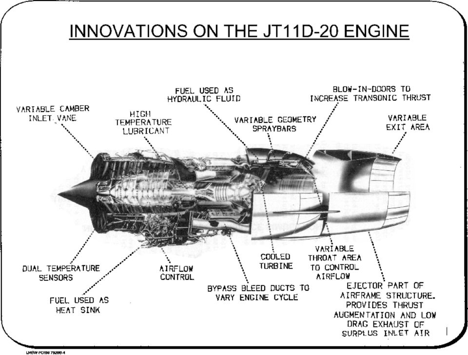
13 THE ENGINE THE ENGINE IS THE PRATT AND WHITNEY JT11D-20, DESIGNATED J58 BY THE MILITARY ENGINE IS A SINGLE-SPOOL, AFTERBURNING TURBO-JET, WITH A 4 th -STAGE BLEED BYPASS DUCTING AIR INTO THE AFTERBURNER BLEED SYSTEM IS OPERATED AT HIGH MACH NUMBERS TO PROVIDE INCREASED COMPRESSOR STALL MARGIN BLEED AIR RE-ENTERS THE ENGINE AHEAD OF THE AFTERBURNER WHERE THE AIR IS USED FOR COOLING AND INCREASED THRUST AUGMENTATION BYPASS AIRFLOW IS 20% OF TOTAL FLOW INTO ENGINE ENGINE RPM IS MAINTAINED BY MODULATING THE EXHAUST NOZZLE THIS ARRANGEMENT PROVIDES NEARLY CONSTANT AIRFLOW AT A GIVEN MACH NUMBER FROM BELOW MILITARY POWER TO MAXIMUM AB, WHICH IS VERY DESIRABLE WHEN OPERATING BEHIND A SUPERSONIC MIXED COMPRESSION INLET

14 J58 Installation in SR-71

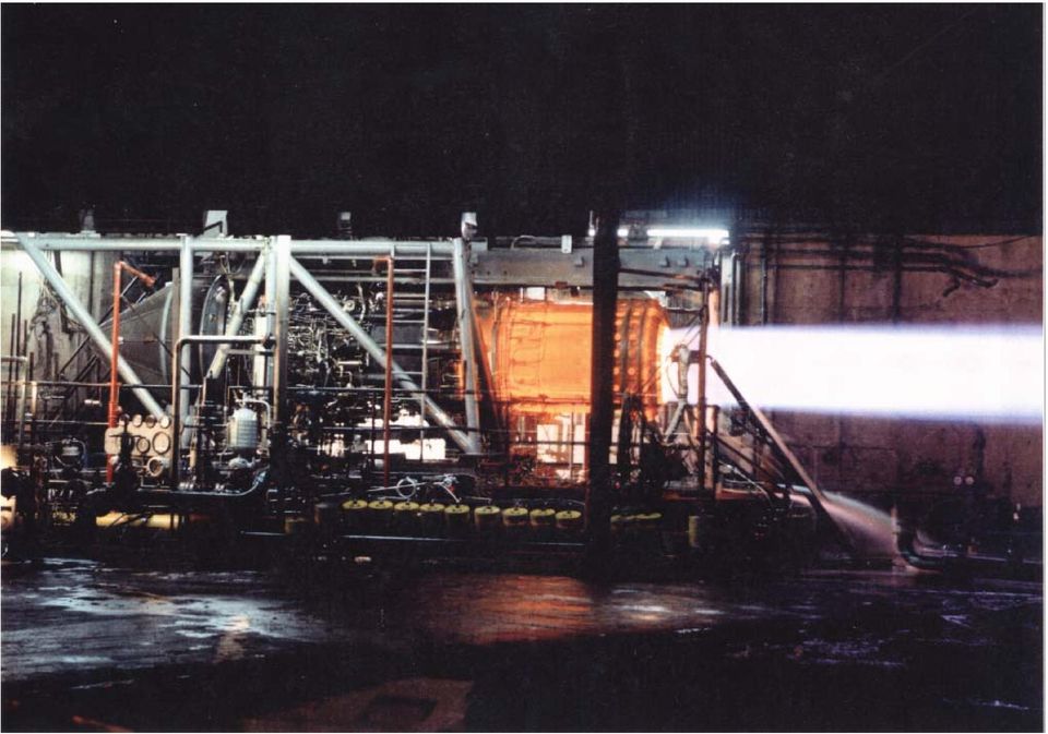
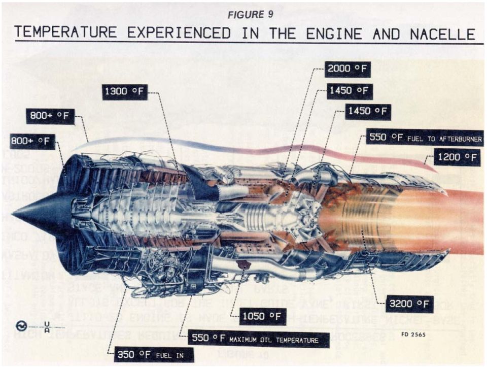
15 J58 ENGINE SYSTEM FUEL CONSUMPTION AT A CRUISING MACH NUMBER IS APPROXIMATELY 8,000 GALLONS PER HOUR FUEL IS JP-7, WHICH HAS AN EXTREMELY LOW VAPOR PRESSURE AND A VERY HIGH FLASH POINT TO LIGHT THIS FUEL A SPECIAL IGNITION SYSTEM IS USED. A CHEMICAL PYROPHORIC TRIETHYLBORANE (TEB), IGNITES THE MAIN ENGINE AND THE AFTERBURNER THE ENGINE OPERATES IN THE MOST HOSTILE ENVIRONMENT ANY ENGINE HAS EVER BEEN SUBJECTED TO: AIR ENTERING THE COMBUSTOR REACHES 1400 o F TURBINE INLET TEMPERATURE IS 2000 o F TEMPERATURE IN AFTERBURNER SECTION REACHES 3200 o F GROUND STARTING REQUIRES USING TWO 300 HP BUICK WILDCAT RACING ENGINES CONNECTED TO THE J58 STARTER DRIVE AT FULL AFTERBURNER POWER THE AFTERBURNER GLOWS CHERRY RED

16
17

18
19
20

21
22
23
24
25 INLET REQUIREMENTS HIGH PRESSURE RECOVERY MINIMUM DRAG AIRFLOW CAPABILITY COMPATIBLE WITH ENGINE AIRFLOW REQUIREMENTS DUCT EXIT AIRFLOW DISTORTION ACCEPTABLE TO ENGINE AIRFLOW SUPPLY TO COOL ENGINE & OPERATE EJECTOR NOZZLE STABLE OPERATION
26 SR-71 AIR INLET DESIGN DRIVERS FUNCTIONAL REQUIREMENTS FOR THE ENGINE INLET MATCH THE AIR FLOW CAPTURED BY THE INLET TO THE AIR FLOW REQUIRED BY THE ENGINE FOR ALL CONDITIONS AT SUPERSONIC CRUISE, REDUCE THE VELOCITY OF THE CAPTURED AIR TO ABOUT 0.4 MACH REQUIRED AT THE ENGINE FACE MAXIMIZE THE PRESSURE RECOVERY AT THE ENGINE FACE WHILE REDUCING VELOCITY MINIMIZE THE TRANSIENT FLOW EFFECTS OF EXTERNAL DISTRUBANCES NO FIXED INLET CONFIGURATION CAN SIMULTANEOUSLY SATISFY THESE REQUIREMENTS OVER THE ENTIRE FLIGHT ENVELOPE AND ENGINE OPERATING RANGES VARIABLE INLET GEOMETRY IS REQUIRED
27
28 INLET BLEED and BYPASS ARRANGEMENT Spike Bleed Exit Aft-Bypass Door Assembly Shock-Trap Flow Tube Forward-Bypass Exit Forward-Bypass Door Opening Spike Support Structure Forward Bypass Door Assembly Cowl Bleed (Shock Trap) Translating Spike Spike Bleed
29 SR-71 AIR INLET CHARACTERISTICS AXI-SYMMETRIC MIXED COMPRESSION INLET CHOSEN BECAUSE LOWER WEIGHT, DRAG, AND SIGNATURE OF AXI-SYMMETRIC DESIRED RANGE AND CRUISE PERFORMANCE REQUIRED PRESSURE RECOVERIES HIGHER THAN POSSIBLE WITH AN EXTERNAL COMPRESSION INLET AT MACH 3.0+ MIXED COMPRESSION INLETS CAN ATTAIN HIGH PRESSURE RECOVERY ABOVE MACH IF NORMAL SHOCK CAN BE KEPT AT THE DESIGN LOCATION JUST DOWNSTREAM OF THE MINIMUM CROSS SECTIONAL FLOW AREA (INLET THROAT) IF NORMAL SHOCK CAN BE MAINTAINED NEAR THE DESIGN LOCATION DURING INTERNAL OR EXTERNAL FLOW PERTURBATIONS IF NORMAL SHOCK CANNOT BE MAINTAINED DOWNSTREAM OF THE THROAT ABOVE MACH 2.2 INLET IS SAID TO BE UNSTARTED NORMAL SHOCK POPS OUT AND STABILIZES FORWARD OF THE INLET LIP PRESSURE RECOVERY, AIR FLOW, AND THRUST DROP TO LOW LEVELS DRAG INCREASES SIGNIFICANTLY INLET MUST BE RESTARTED AS FAST AS POSSIBLE TO PREVENT ENGINE DAMAGE AND MINIMIZE AIRPLANE YAW TRANSIENT
30 INLET SYSTEM INLET HAS A TRANSLATING 26-DEGREE CONE WHICH ACTS AS THE INITIAL DECELERATION OR COMPRESSION SURFACE PRODUCING A SERIES OF SHOCK WAVES UP TO THE INLET THROAT THE SHOCK TRAIN ENDS WITH A FINAL TERMINAL OR NORMAL SHOCK FOLLOWED BY A SUBSONIC DIFFUSER THE PURPOSE OF THE INLET IS TO SUPPLY THE AIR REQUIRED BY THE ENGINE AT THE HIGHEST PRESSURE RECOVERY AND THE LOWEST DRAG, WITH A MINIMUM OF DISTORTION. THIS IS NOT AS SIMPLE AS IT SOUNDS! A TURBOJET ENGINE IS A CONSTANT VOLUME MACHINE. THIS MEANS THAT REGARDLESS OF FLIGHT SPEED FROM M = 0 TO CRUISE SPEED THE SPEED OR MACH NUMBER ENTERING THE ENGINE IS RELATIVELY CONSTANT, BETWEEN M = 0.3 AND 0.5
31 AIR INLET THE SR-71 ENGINE AIR INLET IS A MIXED EXTERNAL AND INTERNAL COMPRESSION, AXI-SYMMETRIC INLET, WITH GRADUAL ISENTROPIC COMPRESSION APPROACHING THE THROAT THE BOUNDARY LAYER WHICH BUILDS UP ON THE CENTERBODY IS REMOVED AHEAD OF THE TERMINAL SHOCK THROUGH A POROUS BLEED THIS BLEED PASSES OVERBOARD THROUGH LOUVERS AT THE ENDS OF THE CENTERBODY SUPPORT STRUTS FORWARD BYPASS DOORS, LOCATED CLOSE TO THE THROAT MATCH THE INLET TO THE ENGINE, BY-PASSING AIR OVERBOARD THE COWL BLEED IS A SHOCK TRAP RAM BLEED WHICH SUPPLIES AIR THROUGH TUBES ACROSS THE BY-PASS DOOR REGION INTO THE ENGINE SECONDARY PASSAGE, WHERE IT IS USED FOR COOLING, AND FED THROUGH TO THE ENGINE EJECTOR AFT BY-PASS FLOW JOINS THE COWL BLEED FLOW AND PASSES THROUGH THE ENGINE EJECTOR THIS BY-PASS WAS INSTALLED TO PROVIDE SUFFICIENT FLOW TO PERMIT ENGINE OPERATION AT IDLE DURING ACCELERATION, AFT BY-PASS IS USED TO REDUCE THE FORWARD OVERBOARD BY-PASS WITH ITS ATTENDANT DRAG
32 INLET SPIKE THE INLET SPIKES REGULATE THE AMOUNT OF AIR ENTERING THE INLET BY MOVING PROGRESSIVELY REARWARDS AS THE AIRCRAFT S SPEED INCREASES THE FULLY FORWARD POSITION WHICH THE SPIKE MAINTAINS UP TO MACH 1.4 THE SPIKE AT THE LIMIT OF ITS 26-INCH AFT TRANSLATION THE CONFIGURATION OF THE INLET AT MACH 3 AND ABOVE AT THIS POINT THE CAPTURE AREA HAS INCREASED BY 112%, WHILE THE THROAT DIAMETER AT THE POINT OF MINIMUM CROSS-SECTION SECTION FURTHER DOWN THE INTAKE HAS DECREASED BY 54% IN ORDER TO HOLD THE TRI-SONIC SHOCKWAVE IN THE CORRECT POSITION AT MACH 2.2 THE INLET PRODUCES 13% OF THE OVERALL THRUST, THE ENGINE AND EJECTOR ACCOUNTING FOR 73% AND 14% RESPECTIVELY THE CORRESPONDING FIGURES AT MAXIMUM CRUISING SPEED, MACH 3+ ARE 54%, 17%, AND 29% MOST OF THE THRUST IS DEVELOPED BY THE INLET SPIKE
33 THRUST PRODUCTION
34 SR-71 INLET/EXHAUST AIRFLOW PATTERNS
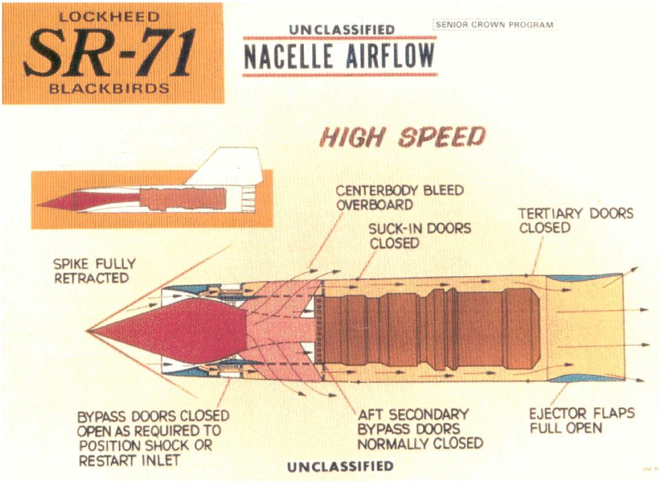
35 Shock Trap Bleed Supplies Engine Cooling Air SR-71 INLET/EXHAUST AIRFLOW PATTERNS Centerbody Bleed Overboard Suck-In Doors Closed Spike Forward Shock Trap Bleed Supplies Engine Cooling Air Aft Bypass Tertiary Doors Open Fwd Bypass Doors Open Doors Closed Ejector Flaps Closed As Required to Position Inlet Shock Centerbody Bleed Overboard Suck-In Doors Closed Spike Retracting Shock Trap Bleed Supplies Engine Cooling Air Aft Bypass Doors Position B Tertiary Doors Closed Fwd Bypass Doors Open Ejector Flaps Opening As Required to Position Inlet Shock Centerbody Bleed Overboard Suck-In Doors Closed Spike Retracted FWD Bypass Doors Closed Fwd Bypass Doors Closed Aft Bypass Doors Closed Will Open as Required to Position Inlet Shock Tertiary Doors Closed Ejector Flaps Open
36 CENTERBODY BLEED ARRANGEMENT Support Strut Spike Bleed Exit Louvers (4 Locations) Spike Bleed Exit Louver View Looking AFT Support Strut Spike Bleed (Slotted Surface) Engine Face Side View
37 FORWARD BYPASS Shock Trap Tubes Bypass Exit Louvers (6 Locations) Rotary Flush Sliding Doors Bypass Exit Louvers A Forward Bypass Flow SECTION A-A Aft Bypass Doors Engine Face A Forward Bypass Doors
38 SECONDARY FLOW SYSTEMS COWL BLEED AND AFT BYPASS Shock Trap Flow Shock Trap Tubes To Ejector Aft Bypass Flow Engine Face Shock Trap Aft Bypass Doors Side View Engine Bay
39 INLET CONFIGURATION AND CONTROL THE INLET UTILIZES DAFICS COMPUTERS FOR CONTROL OF SPIKE AND BYPASS DOORS SPIKE MOVEMENT IS CONTROLLED BY MACH NUMBER, ANGLE OF ATTACK, ANGLE OF YAW, AND LOAD FACTOR THE TERMINAL SHOCK POSITION IS CONTROLLED AND REGULATED BY FORWARD AND AFT BYPASS DOORS WHICH MATCH THE INLET AIR SWALLOWING CAPABILITY TO THE ENGINE REQUIREMENT THE COMPRESSION RATIO AT CRUISE IS 40 TO 1 AT CRUISE, EACH INLET SWALLOWS APPROXIMATELY 100,000 CUBIC FEET OF AIR PER SECOND EQUIVALENT TO TWO MILLION PEOPLE BREATHING ON THE GROUND INLETS CANTED INBOARD 3.2 O EFFECT OF CHINE and FUSELAGE INLETS CANTED DOWN 5.6 O EFFECT OF ANGLE OF ATTACK AT CRUISE
40 SR-71 AIR INLET CONTROL SYSTEM FUNCTIONS FORWARD BYPASS DOORS ARE OPEN WITH THE GEAR DOWN, CLOSE WHEN LANDING GEAR RETRACTS, BUT BEGIN TO OPEN AGAIN AT MACH 1.4 TO DUMP EXCESS FLOW CAPTURED BY INLET SPIKE IS FULL FORWARD AT LOW MACH NUMBERS AND IS PROGRESSIVELY RETRACTED FOR MACH NUMBERS ABOVE 1.6 CONTROL SYSTEM POSITIONS SPIKE AS A FUNCTION OF MACH NUMBER WITH AOA, SLIDESLIP, AND NORMAL ACCELERATION BIAS NORMAL SHOCK MOVES DOWNSTREAM OF THE INLET THROAT (INLET STARTS) AT APROXIMATELY MACH 1.7 ABOVE MACH BYPASS DOORS MODULATE AS REQUIRED TO KEEP NORMAL SHOCK AT THE DESIGN LOCATION IF AN UNSTART OCCURS IN ONE INLET ABOVE MACH 2.3, BOTH SPIKES ARE DRIVEN TO THE FORWARD POSITION AND THE FORWARD BYPASS DOORS ARE OPENED TO OBTAIN A RESTART AND MINIMIZE YAW TRANSIENTS AFT BYPASS DOORS ARE SCHEDULED MANUALLY TO PROVIDE COOLING AIR TO ENGINE BAY AND EJECTOR
41
42 EJECTOR NOZZLE THE LAST PART OF THE PROPULSION SYSTEM IS THE EJECTOR THE EJECTOR PERFORMS THE REVERSE FUNCTION OF THE INLET IT ACCELERATES THE AIR COMING OUT OF THE TURBINE AT M = 0.4 UP TO M = 3.0+ THE EXIT VELOCITY MUST MATCH OR EXCEED THE FLIGHT SPEED, THEREFORE THE VARIABLE EXIT FLAPS. THEY STAY FULLY CLOSED UNTIL ABOUT M = 1.2, AND ARE FULLY OPEN AT ABOUT M = 3.2 PRIMARY NOZZLE IS A RING OF BLOW-IN DOORS WHICH PROVIDE TERTIARY AIR TO FILL IN THE EJECTOR AT MACH NUMBERS BELOW 1.2 TERTIARY AIR IS PROVIDED BY SUCK-IN DOORS AROUND THE NACELLE, AUGMENTED BY THE COWL (SHOCK TRAP BLEED AND AFT BY-PASS BLEED) MAIN EJECTOR IS SUPPORTED DOWNSTREAM ON STREAMLINED STRUTS AND A RING OF RENE 41 STEEL ALLOY ON WHICH ARE HINGED FREE-FLOATING TRAILING EDGE FLAPS OF HASTELLOY X
43
44 REFERENCES: 1. Connors, Jack, The Engines of Pratt & Whitney: A Technical History, AIAA (American Institute of Aeronautics and Astronautics, Inc.), Reston, VA, 2010, pp St. Peter, J., The History of Aircraft Gas Turbine Engine Development in the United States: A Tradition of Excellence, ASME, New York, 1999, pp Campbell, David H., F-12 Series Aircraft Propulsion System Performance and Development, AIAA No , Also found in AIAA Journal of Aircraft, Vol. 11, No. 11, November 1974, pp Note: This paper presents information only up to Mach 3.0 due to security restrictions at that time. 4. California Institute of Technology, Course Ae107, Case Studies in Engineering: The Lockheed SR-71 Blackbird, Spring Published by Cal Tech for course students and presenters only. 5. Anderson, J. Thomas, unpublished training course syllabus, How Supersonic Inlets Work: Details of The Geometry And Operation Of The SR-71 Mixed Compression Inlet, 2013.
INLET AND EXAUST NOZZLES Chap. 10 AIAA AIRCRAFT ENGINE DESIGN R01-07/11/2011
 MASTER OF SCIENCE IN AEROSPACE ENGINEERING PROPULSION AND COMBUSTION INLET AND EXAUST NOZZLES Chap. 10 AIAA AIRCRAFT ENGINE DESIGN R01-07/11/2011 LECTURE NOTES AVAILABLE ON https://www.ingegneriaindustriale.unisalento.it/scheda_docente/-/people/antonio.ficarella/materiale
ME 239: Rocket Propulsion. Over- and Under-expanded Nozzles and Nozzle Configurations. J. M. Meyers, PhD
 ME 239: Rocket Propulsion Over- and Under-expanded Nozzles and Nozzle Configurations J. M. Meyers, PhD 1 Over- and Underexpanded Nozzles Underexpanded Nozzle Discharges fluid at an exit pressure greater
Fundamentals of Pulse Detonation Engine (PDE) and Related Propulsion Technology
 and Related Propulsion Technology") Fundamentals of Pulse Detonation Engine (PDE) and Related Propulsion Technology Dora E. Musielak, Ph.D. Aerospace Engineering Consulting Arlington, TX All rights reserved. No part of this publication may
Fundamentals of Pulse Detonation Engine (PDE) and Related Propulsion Technology Dora E. Musielak, Ph.D. Aerospace Engineering Consulting Arlington, TX All rights reserved. No part of this publication may
CFD Analysis of Supersonic Exhaust Diffuser System for Higher Altitude Simulation
 Page1 CFD Analysis of Supersonic Exhaust Diffuser System for Higher Altitude Simulation ABSTRACT Alan Vincent E V P G Scholar, Nehru Institute of Engineering and Technology, Coimbatore Tamil Nadu A high
Jet Propulsion. Lecture-2. Ujjwal K Saha, Ph.D. Department of Mechanical Engineering Indian Institute of Technology Guwahati 1
 Lecture-2 Prepared under QIP-CD Cell Project Jet Propulsion Ujjwal K Saha, Ph.D. Department of Mechanical Engineering Indian Institute of Technology Guwahati 1 Simple Gas Turbine Cycle A gas turbine that
Propulsion (1): Jet Engine Basics
: Jet Engine Basics") FLIGHT OPERATIONS ENGINEERING Propulsion (1): Jet Engine Basics P1, Page 1 Propulsion (1): Jet Engine Basics Jet Engine Fundamentals (Videos) Types of Jet Engines Propulsive Efficiency and the Thrust Equation
FLIGHT OPERATIONS ENGINEERING Propulsion (1): Jet Engine Basics P1, Page 1 Propulsion (1): Jet Engine Basics Jet Engine Fundamentals (Videos) Types of Jet Engines Propulsive Efficiency and the Thrust Equation
AIRCRAFT GENERAL www.theaviatornetwork.com GTM 1.1 2005 1-30-05 CONTENTS
 www.theaviatornetwork.com GTM 1.1 CONTENTS INTRODUCTION... 1.2 GENERAL AIRPLANE... 1.2 Fuselage... 1.2 Wing... 1.2 Tail... 1.2 PROPELLER TIP CLEARANCE... 1.2 LANDING GEAR STRUT EXTENSION (NORMAL)... 1.2
CAT VIII WORKING DRAFT
 Category VIII Military Aircraft and Associated Equipment A. End Items, Systems, Accessories, Attachments, Equipment, Parts and Components 1. Fighter, bomber, attack, or specialized fixed or rotary wing
TYPE-CERTIFICATE DATA SHEET
 TYPE-CERTIFICATE DATA SHEET EASA TC E.036 for Trent 1000 series engines Certificate Holder Rolls-Royce plc PO Box 31 Derby DE24 8BJ United Kingdom For Models: Trent 1000-A Trent 1000-A2 Trent 1000-AE Trent
Mechanical Design of Turbojet Engines. An Introduction
 Mechanical Design of Turbomachinery Mechanical Design of Turbojet Engines An Introduction Reference: AERO0015-1 - MECHANICAL DESIGN OF TURBOMACHINERY - 5 ECTS - J.-C. GOLINVAL University of Liege (Belgium)
CC RH A STUDY ON THE OPTIMIZATION OF JET ENGINES FOR COMBAT AIRCRAFTS. C. SSnchez Tarifa* E. Mera Diaz**
 A STUDY ON THE OPTIMIZATION OF JET ENGINES FOR COMBAT AIRCRAFTS C. SSnchez Tarifa* E. Mera Diaz** Abstract In the paper the optimization of jet engines for combat aircrafts is discussed. This optimization
The Aircraft Engine Design Project Fundamentals of Engine Cycles
 GE Aviation The Aircraft Engine Design Project Fundamentals of Engine Cycles Spring 2009 Ken Gould Phil Weed 1 GE Aviation Technical History I-A - First U.S. jet engine (Developed in Lynn, MA, 1941) U.S.
APP Aircraft Performance Program Demo Notes Using Cessna 172 as an Example
 APP Aircraft Performance Program Demo Notes Using Cessna 172 as an Example Prepared by DARcorporation 1. Program Layout & Organization APP Consists of 8 Modules, 5 Input Modules and 2 Calculation Modules.
CO 2 41.2 MPa (abs) 20 C
 20 C") comp_02 A CO 2 cartridge is used to propel a small rocket cart. Compressed CO 2, stored at a pressure of 41.2 MPa (abs) and a temperature of 20 C, is expanded through a smoothly contoured converging nozzle
comp_02 A CO 2 cartridge is used to propel a small rocket cart. Compressed CO 2, stored at a pressure of 41.2 MPa (abs) and a temperature of 20 C, is expanded through a smoothly contoured converging nozzle
A. Hyll and V. Horák * Department of Mechanical Engineering, Faculty of Military Technology, University of Defence, Brno, Czech Republic
 AiMT Advances in Military Technology Vol. 8, No. 1, June 2013 Aerodynamic Characteristics of Multi-Element Iced Airfoil CFD Simulation A. Hyll and V. Horák * Department of Mechanical Engineering, Faculty
Fluid Mechanics Prof. S. K. Som Department of Mechanical Engineering Indian Institute of Technology, Kharagpur
 Fluid Mechanics Prof. S. K. Som Department of Mechanical Engineering Indian Institute of Technology, Kharagpur Lecture - 20 Conservation Equations in Fluid Flow Part VIII Good morning. I welcome you all
Chapter 2. Basic Airplane Anatomy. 2008 Delmar, Cengage Learning
 Chapter 2 Basic Airplane Anatomy Objectives Identify components of basic aircraft anatomy Understand aircraft size and weight categories List different types and examples of General aviation aircraft Military
On Hammershock Propagation in a Supersonic Flow Field
 NASA/TM 2002-211717 On Hammershock Propagation in a Supersonic Flow Field A. Robert Porro Glenn Research Center, Cleveland, Ohio July 2002 The NASA STI Program Office... in Profile Since its founding,
787 No-Bleed Systems: Saving Fuel and Enhancing Operational Efficiencies
 787 No-Bleed Systems: Saving Fuel and Enhancing Operational Efficiencies by ike Sinnett, Director, 787 Systems The Boeing 787 Dreamliner features a unique systems architecture that offers numerous advantages
APPENDIX 3-B Airplane Upset Recovery Briefing. Briefing. Figure 3-B.1
 APPENDIX 3-B Airplane Upset Recovery Briefing Industry Solutions for Large Swept-Wing Turbofan Airplanes Typically Seating More Than 100 Passengers Briefing Figure 3-B.1 Revision 1_August 2004 Airplane
Toward Zero Sonic-Boom and High Efficiency. Supersonic Bi-Directional Flying Wing
 AIAA Paper 2010-1013 Toward Zero Sonic-Boom and High Efficiency Supersonic Flight: A Novel Concept of Supersonic Bi-Directional Flying Wing Gecheng Zha, Hongsik Im, Daniel Espinal University of Miami Dept.
Compiled by Matt Zagoren
 The information provided in this document is to be used during simulated flight only and is not intended to be used in real life. Attention VA's - you may post this file on your site for download. Please
Wing Design: Major Decisions. Wing Area / Wing Loading Span / Aspect Ratio Planform Shape Airfoils Flaps and Other High Lift Devices Twist
 Wing Design: Major Decisions Wing Area / Wing Loading Span / Aspect Ratio Planform Shape Airfoils Flaps and Other High Lift Devices Twist Wing Design Parameters First Level Span Area Thickness Detail Design
g GEAE The Aircraft Engine Design Project- Engine Cycles Design Problem Overview Spring 2009 Ken Gould Phil Weed GE Aircraft Engines
 GEAE The Aircraft Engine Design Project- Engine Cycles Design Problem Overview Spring 2009 Ken Gould Phil Weed 1 Background The Aircraft Engine Design Project- Engine Cycles A new aircraft application
This file contains the full script of the corresponding video, published on YouTube. November 2014: http://youtu.be/wbu6x0hsnby
 This file contains the full script of the corresponding video, published on YouTube. November 2014: http://youtu.be/wbu6x0hsnby Background papers and links to formal FAA and EASA Aviation Regulations and
European Aviation Safety Agency
 European Aviation Safety Agency EASA TYPE CERTIFICATE DATA SHEET Number : IM.E.026 Issue : 04 Date : 04 April 2014 Type : Engine Alliance LLC GP7200 series engines Models: GP7270 GP7272 GP7277 List of
Forces on the Rocket. Rocket Dynamics. Equation of Motion: F = Ma
 Rocket Dynamics orces on the Rockets - Drag Rocket Stability Rocket Equation Specific Impulse Rocket otors Thrust orces on the Rocket Equation of otion: = a orces at through the Center of ass Center of
AIR CONDITIONING & PRESSURIZATION
 Smartcockpit.com BOEING 737 SYSTEMS REVIEW Page 1 AIR CONDITIONING & PRESSURIZATION 1. GENERAL Conditioned air comes from either the aircraft air-conditioning system or a preconditioned ground source.
Science in. Wind WHAT S GOING ON? In the Terminal or in the Airplane. Try This:
 Science in Your Airplane Seat Why are airplane wings shaped the way they are? What can pretzels tell you about flying? Instead of catching a nap or flipping through the in-flight magazine, do some experiments
COMBUSTION SYSTEMS - EXAMPLE Cap. 9 AIAA AIRCRAFT ENGINE DESIGN www.amazon.com
 CORSO DI LAUREA MAGISTRALE IN Ingegneria Aerospaziale PROPULSION AND COMBUSTION COMBUSTION SYSTEMS - EXAMPLE Cap. 9 AIAA AIRCRAFT ENGINE DESIGN www.amazon.com LA DISPENSA E DISPONIBILE SU www.ingindustriale.unisalento.it
AIRCRAFT PERFORMANCE Pressure Altitude And Density Altitude
 Performance- Page 67 AIRCRAFT PERFORMANCE Pressure Altitude And Density Altitude Pressure altitude is indicated altitude corrected for nonstandard pressure. It is determined by setting 29.92 in the altimeter
AIR - PNEUMATIC, AIR CONDITIONING, PRESSURIZATION
 AIR - PNEUMATIC, AIR CONDITIONING, PRESSURIZATION PNEUMATIC SYSTEM The Pneumatic System is normally supplied by the Engine's compressor sections. The Pneumatic System may also be supplied by APU bleed
Cessna Skyhawk II / 100. Performance Assessment
 Cessna Skyhawk II / 100 Performance Assessment Prepared by John McIver B.Eng.(Aero) Temporal Images 23rd January 2003 http://www.temporal.com.au Cessna Skyhawk II/100 (172) Performance Assessment 1. Introduction
OUTLINE SHEET 5-1-1 PRINCIPLES OF GAS TURBINE OPERATION
 Sheet 1 of 2 OUTLINE SHEET 5-1-1 PRINCIPLES OF GAS TURBINE OPERATION A. INTRODUCTION This lesson topic introduces some basic propulsion theory as it applies to the gas turbine engine and explains some
Programme Discussions Wissenschaftstag Braunschweig 2015 Laminarität für zukünftige Verkehrsflugzeuge
 Programme Discussions Wissenschaftstag Braunschweig 2015 Kevin Nicholls, EIVW Prepared by Heinz Hansen TOP-LDA Leader, ETEA Presented by Bernhard Schlipf, ESCRWG Laminarität für zukünftige Verkehrsflugzeuge
AE 430 - Stability and Control of Aerospace Vehicles
 AE 430 - Stability and Control of Aerospace Vehicles Atmospheric Flight Mechanics 1 Atmospheric Flight Mechanics Performance Performance characteristics (range, endurance, rate of climb, takeoff and landing
Computational Aerodynamic Analysis on Store Separation from Aircraft using Pylon
 International Journal of Engineering Science Invention (IJESI) ISSN (Online): 2319 6734, ISSN (Print): 2319 6726 www.ijesi.org ǁ PP.27-31 Computational Aerodynamic Analysis on Store Separation from Aircraft
AVIATION OCCURRENCE REPORT A98W0192 ENGINE FAILURE
 Transportation Safety Board of Canada Bureau de la sécurité des transports du Canada AVIATION OCCURRENCE REPORT A98W0192 ENGINE FAILURE MARTINAIR HOLLAND N.V. BOEING 767-300 PH-MCI CALGARY INTERNATIONAL
Cessna 172SP & NAV III Maneuvers Checklist
 Cessna 172SP & NAV III Maneuvers Checklist Introduction Power Settings This document is intended to introduce to you the standard method of performing maneuvers in Sunair Aviation s Cessna 172SP and NAV
Fundamentals of Aircraft Turbine Engine Control
 Fundamentals of Aircraft Turbine Engine Control Dr. Sanjay Garg Chief, Ph: (216) 433-2685 FAX: (216) 433-8990 email: sanjay.garg@nasa.gov http://www.lerc.nasa.gov/www/cdtb Outline The Engine Control Problem
General aviation & Business System Level Applications and Requirements Electrical Technologies for the Aviation of the Future Europe-Japan Symposium
 General aviation & Business System Level Applications and Requirements Electrical Technologies for the Aviation of the Future Europe-Japan Symposium 26 March 2015 2015 MITSUBISHI HEAVY INDUSTRIES, LTD.
AOE 3104 Aircraft Performance Problem Sheet 2 (ans) Find the Pressure ratio in a constant temperature atmosphere:
 Find the Pressure ratio in a constant temperature atmosphere:") AOE 3104 Aircraft Performance Problem Sheet 2 (ans) 6. The atmosphere of Jupiter is essentially made up of hydrogen, H 2. For Hydrogen, the specific gas constant is 4157 Joules/(kg)(K). The acceleration
AOE 3104 Aircraft Performance Problem Sheet 2 (ans) 6. The atmosphere of Jupiter is essentially made up of hydrogen, H 2. For Hydrogen, the specific gas constant is 4157 Joules/(kg)(K). The acceleration
SINGLE ENGINE TURBO-PROP AEROPLANE ENDORSEMENT
 SINGLE ENGINE TURBO-PROP AEROPLANE ENDORSEMENT ENGINEERING, DATA AND PERFORMANCE QUESTIONNAIRE FOR (Aeroplane make & model) Version 1-31 August 1996 Name: Endorser: (Signature/Name) Satisfactorily Completed
Aeronautical Testing Service, Inc. 18820 59th DR NE Arlington, WA 98223 USA. CFD and Wind Tunnel Testing: Complimentary Methods for Aircraft Design
 Aeronautical Testing Service, Inc. 18820 59th DR NE Arlington, WA 98223 USA CFD and Wind Tunnel Testing: Complimentary Methods for Aircraft Design Background Introduction ATS Company Background New and
PRELIMINARY INVENTORY K0567 (KA1706, KA2285) DAN REX CORNWELL (1930- ) PAPERS [TWA]
![PRELIMINARY INVENTORY K0567 (KA1706, KA2285) DAN REX CORNWELL (1930- ) PAPERS [TWA]](/thumbs/33/15981195.jpg "PRELIMINARY INVENTORY K0567 (KA1706, KA2285) DAN REX CORNWELL (1930- ) PAPERS [TWA]") PRELIMINARY INVENTORY K0567 (KA1706, KA2285) DAN REX CORNWELL (1930- ) PAPERS [TWA] This collection is available at The State Historical Society of Missouri Research Center- Kansas City. If you would like
PRELIMINARY INVENTORY K0567 (KA1706, KA2285) DAN REX CORNWELL (1930- ) PAPERS [TWA] This collection is available at The State Historical Society of Missouri Research Center- Kansas City. If you would like
MODULE 11B. PISTON AEROPLANE AERODYNAMICS, STRUCTURES AND SYSTEMS
 MODULE 11B. PISTON AEROPLANE AERODYNAMICS, STRUCTURES AND SYSTEMS Note: The scope of this Module should reflect the technology of aeroplanes pertinent to the A2 and B1.2 subcategory. 11.1 Theory of Flight
Program Update June 2015. G500, G600 Program Update 06.15
 Program Update June 2015 G500, G600 Program Update 06.15 All-New Gulfstream G500 and G600 All new, best-in-class aircraft that build upon Gulfstream s technology leadership Unmatched high-speed range capability
FUNDAMENTALS OF GAS TURBINE ENGINES
 FUNDAMENTALS OF GAS TURBINE ENGINES INTRODUCTION The gas turbine is an internal combustion engine that uses air as the working fluid. The engine extracts chemical energy from fuel and converts it to mechanical
Performance. Power Plant Output in Terms of Thrust - General - Arbitrary Drag Polar
 Performance 11. Level Flight Performance and Level flight Envelope We are interested in determining the maximum and minimum speeds that an aircraft can fly in level flight. If we do this for all altitudes,
TYPE CERTIFICATE DATA SHEET Nº EA-2011T03 Type Certificate Holder: COSTRUZIONI AERONAUTICHE TECNAM S.r.l. Via Tasso, 478 80127 - Napoli Italy
 TYPE CERTIFICATE DATA SHEET Nº EA-2011T03 Type Certificate Holder: COSTRUZIONI AERONAUTICHE TECNAM S.r.l. Via Tasso, 478 80127 - Napoli Italy EA-2011T03-02 Sheet 01 TECNAM P2006T 04 May 2012 This data
Lockheed Martin s. Affordable Stealth
 Lockheed Martin s Affordable Stealth November 15, 2000 Brett S. Haisty Lockheed Martin Aeronautics, Washington, D.C. N a t i o n a l P r e s s C l u b W a s h i n g t o n, D. C. 1 5 N o v e m b e r 2 0
UPPER-SURFACE BLOWING NACELLE DESIGN STUDY FOR A SWEPT WING AIRPLANE AT CRUISE CONDITIONS
 NASA CONTRACTOR REPORT NASA CR-2427 "8 a UPPER-SURFACE BLOWING NACELLE DESIGN STUDY FOR A SWEPT WING AIRPLANE AT CRUISE CONDITIONS by W. B. Gillette, L. W. Mohn, H. G. Ridley, and T. C. Nark Prepared by
CHAPTER 7 CLIMB PERFORMANCE
 CHAPTER 7 CLIMB PERFORMANCE 7 CHAPTER 7 CLIMB PERFORMANCE PAGE 7.1 INTRODUCTION 7.1 7.2 PURPOSE OF TEST 7.1 7.3 THEORY 7.2 7.3.1 SAWTOOTH CLIMBS 7.2 7.3.2 STEADY STATE APPROACH TO CLIMB PERFORMANCE 7.4
High-Lift Systems. High Lift Systems -- Introduction. Flap Geometry. Outline of this Chapter
 High-Lift Systems Outline of this Chapter The chapter is divided into four sections. The introduction describes the motivation for high lift systems, and the basic concepts underlying flap and slat systems.
FUEL STORAGE Chap. 3 AIRCRAFT FUEL SYSTEMS
 UNIVERSITY OF SALENTO SCHOOL OF INDUSTRIAL ENGINEERING DEPT. OF ENGINEERING FOR INNOVATION Lecce-Brindisi (Italy) MASTER OF SCIENCE IN AEROSPACE ENGINEERING PROPULSION AND COMBUSTION FUEL STORAGE Chap.
Mathematically Modeling Aircraft Fuel Consumption
 Mathematically Modeling Aircraft Fuel Consumption by Kevin Pyatt, Department of Education Jacqueline Coomes, Department of Mathematics Eastern Washington University, Cheney, WA CoCal Airlines April 9,
Lift and Drag on an Airfoil ME 123: Mechanical Engineering Laboratory II: Fluids
 Lift and Drag on an Airfoil ME 123: Mechanical Engineering Laboratory II: Fluids Dr. J. M. Meyers Dr. D. G. Fletcher Dr. Y. Dubief 1. Introduction In this lab the characteristics of airfoil lift, drag,
CIRRUS AIRPLANE MAINTENANCE MANUAL
 UNSCHEDULED MAINTENANCE CHECKS 1. DESCRIPTION The following describes those maintenance checks and inspections on the aircraft which are dictated by special or unusual conditions which are not related
An insight into some innovative cycles for aircraft propulsion
 731 An insight into some innovative cycles for aircraft propulsion G Corchero 1, J L Montañés 1, D Pascovici 2, and S Ogaji 2 1 Universidad Politécnica de Madrid (UPM), E. T. S. Ingenieros Aeronáuticos,
RECYCLING OLD WEIGHT ASSESSMENT METHODS AND GIVING THEM NEW LIFE IN AIRCRAFT CONCEPTUAL DESIGN
 28 TH INTERNATIONAL CONGRESS OF THE AERONAUTICAL SCIENCES Abstract RECYCLING OLD WEIGHT ASSESSMENT METHODS AND GIVING THEM NEW LIFE IN AIRCRAFT CONCEPTUAL DESIGN Aircraft conceptual design is an iterative
Fundamentals of Airplane Flight Mechanics
 Fundamentals of Airplane Flight Mechanics David G. Hull Fundamentals of Airplane Flight Mechanics With 125 Figures and 25 Tables 123 David G. Hull The University of Texas at Austin Aerospace Engineering
Phenom 100-350 Hours/Annually
 Phenom 100-350 Hours/Annually Annual & Hourly Cost Detail Embraer Phenom 100 GENERAL PARAMETERS Min Crew / Max Passengers 1 / 8 Seats Full Range (NM / SM) 750.00 / 863.08 Normal Cruise Speed (KTS / MPH)
Detonation Waves and Pulse Detonation Engines
 Detonation Waves and Pulse Detonation Engines E. Wintenberger and J.E. Shepherd Explosion Dynamics Laboratory, Graduate Aeronautical Laboratories, California Institute of Technology, Pasadena, CA 95 Ae03,
Chapter 17. For the most part, we have limited our consideration so COMPRESSIBLE FLOW. Objectives
 Chapter 17 COMPRESSIBLE FLOW For the most part, we have limited our consideration so far to flows for which density variations and thus compressibility effects are negligible. In this chapter we lift this
MULTI-ENGINE TURBO-PROP AEROPLANE ENDORSEMENT
 MULTI-ENGINE TURBO-PROP AEROPLANE ENDORSEMENT ENGINEERING, DATA AND PERFORMANCE QUESTIONNAIRE FOR (Aeroplane make & model) Version 1 -August 1996 Name: ARN. Endorser: ARN: (Signature/Name) 1 The endorsement
General Characteristics
 This is the third of a series of Atlantic Sun Airways CAT C pilot procedures and checklists for our fleet. Use them with good judgment. Note, the start procedures may vary from FS9 Panel to Panel. However
HALE UAV: AeroVironment Pathfinder
 HALE UAV: AeroVironment Pathfinder Aerodynamic and Stability Analysis Case Study: Planform Optimization Desta Alemayehu Elizabeth Eaton Imraan Faruque Photo courtesy NASA Dryden Photo Gallery 1 Pathfinder
ENGINE FIRE / SEVERE DAMAGE / SEPARATION ON TAKEOFF
 ENGINE FIRE / SEVERE DAMAGE / SEPARATION ON TAKEOFF According to RYANAIR Procedures PF PM REMARKS Control the aircraft (FULL T/O thrust can be manually selected) Announce «ENGINE FAILURE» or «ENGINE FIRE»
FLIGHT CONTROLS 1. GENERAL 2. MAIN COMPONENTS AND SUBSYSTEMS ROLL CONTROL. Smartcockpit.com BOEING 737 SYSTEMS REVIEW Page 1
 Smartcockpit.com BOEING 737 SYSTEMS REVIEW Page 1 FLIGHT CONTROLS 1. GENERAL The primary flight controls, ailerons, elevators and rudders, are hydraulically powered. Hydraulic power is provided from hydraulic
MULTI-ENGINE PISTON AEROPLANE ENDORSEMENT
 MULTI-ENGINE PISTON AEROPLANE ENDORSEMENT ENGINEERING, DATA AND PERFORMANCE QUESTIONNAIRE FOR---------------------------------------------------------------------------------------------------------- (Aeroplane
Aircraft (CS-25, CS-22, CS-23, CS-VLA, CS-LSA) ALENIA AERMACCHI
 ALENIA AERMACCHI") EASA.A.586 Description: Language: TCDS: Product type: Manufacturer/TC Holder: A.586 Alenia English EASA.A.586 Aircraft (CS-25, CS-22, CS-23, CS-VLA, CS-LSA) ALENIA AERMACCHI European Aviation Safety Agency:
EASA.A.586 Description: Language: TCDS: Product type: Manufacturer/TC Holder: A.586 Alenia English EASA.A.586 Aircraft (CS-25, CS-22, CS-23, CS-VLA, CS-LSA) ALENIA AERMACCHI European Aviation Safety Agency:
This is the third of a series of Atlantic Sun Airways CAT B pilot procedures and checklists for our fleet. Use them with good judgment.
 This is the third of a series of Atlantic Sun Airways CAT B pilot procedures and checklists for our fleet. Use them with good judgment. Dimensions: Span 107 ft 10 in Length 147 ft 10 in Height 29ft 7 in
Annual & Hourly Cost Detail
 CL604 vs Legacy 600 Annual & Hourly Cost Detail Bombardier Challenger 604 GENERAL PARAMETERS Min Crew / Max Passengers 2 / 9 Seats Full Range (NM / SM) 3862.24 / 4441.58 Normal Cruise Speed (KTS / MPH)
European Aviation Safety Agency
 European Aviation Safety Agency ED Decision 2003/2/RM Final 17/10/2003 The Executive Director DECISION NO. 2003/2/RM OF THE EXECUTIVE DIRECTOR OF THE AGENCY of 17 October 2003 on certification specifications,
Technologies for Re-entry Vehicles. SHEFEX and REX FreeFlyer, DLR s Re-Entry Program. Hendrik Weihs. Folie 1. Vortrag > Autor > Dokumentname > Datum
 Technologies for Re-entry Vehicles SHEFEX and REX FreeFlyer, DLR s Re-Entry Program Hendrik Weihs Folie 1 DLR`s Re-Entry Program, Why? Re-entry or return technology respectively, is a strategic key competence
Air Vehicle Energy Management, Bringing Adaptive Engines, Systems, and Avionics together in an Optimized Way
 Tuesday, October 30 Opening Plenary Session 9:00 11:30 a.m. Keynote Speakers: Air Vehicle Energy Management, Bringing Adaptive Engines, Systems, and Avionics together in an Optimized Way Bob Witwer Vice
ESTIMATING R/C MODEL AERODYNAMICS AND PERFORMANCE
 ESTIMATING R/C MODEL AERODYNAMICS AND PERFORMANCE Adapted from Dr. Leland M. Nicolai s Write-up (Technical Fellow, Lockheed Martin Aeronautical Company) by Dr. Murat Vural (Illinois Institute of Technology)
Airbreathing Rotating Detonation Wave Engine Cycle Analysis
 46th AIAA/ASME/SAE/ASEE Joint Propulsion Conference & Exhibit 5-8 July 010, Nashville, TN AIAA 010-7039 Airbreathing Rotating Detonation Wave Engine Cycle Analysis Eric M. Braun, Frank K. Lu, Donald R.
European Aviation Safety Agency
 TCDS No.: EASA.IM.A.348 Gulfstream G280 Page 1 of 14 European Aviation Safety Agency EASA TYPE-CERTIFICATE DATA SHEET No. EASA.IM.A.348 for Gulfstream G280 Type Certificate Holder: GULFSTREAM AEROSPACE
AIRCRAFT WORK BREAKDOWN STRUCTURE (WBS) LEVELS (FROM MILITARY SPECIFICATION 881)
 LEVELS (FROM MILITARY SPECIFICATION 881)") Appendix C AIRCRAFT WORK BREAKDOWN STRUCTURE (WBS) LEVELS (FROM MILITARY SPECIFICATION 881) Level 1 Level 2 Level 3 Aircraft System Air Vehicle (AV) System Engineering/ Program Management Airframe Propulsion
Appendix C AIRCRAFT WORK BREAKDOWN STRUCTURE (WBS) LEVELS (FROM MILITARY SPECIFICATION 881) Level 1 Level 2 Level 3 Aircraft System Air Vehicle (AV) System Engineering/ Program Management Airframe Propulsion
Fundamental Aeronautics Student Competition High School Division (Advanced Curriculum): 2008-2009 Academic Year
: 2008-2009 Academic Year") Fundamental Aeronautics Student Competition High School Division (Advanced Curriculum): 2008-2009 Academic Year THE Lazarus T1 Arcadia High School 180 Campus Drive Arcadia, CA 91006 2008-2009 School Year
Fundamental Aeronautics Student Competition High School Division (Advanced Curriculum): 2008-2009 Academic Year THE Lazarus T1 Arcadia High School 180 Campus Drive Arcadia, CA 91006 2008-2009 School Year
RITTER Multiple Sonic Nozzle Calibration System
 RITTER Multiple Sonic Nozzle Calibration System »Wouldn t it be great to eliminate doubtful measurement results by using proven measurement technology? Providing the most precise results ensures and increases
Design and Structural Analysis of the Ribs and Spars of Swept Back Wing
 Design and Structural Analysis of the Ribs and Spars of Swept Back Wing Mohamed Hamdan A 1, Nithiyakalyani S 2 1,2 Assistant Professor, Aeronautical Engineering & Srinivasan Engineering College, Perambalur,
CFD Analysis of Swept and Leaned Transonic Compressor Rotor
 CFD Analysis of Swept and Leaned Transonic Compressor Nivin Francis #1, J. Bruce Ralphin Rose *2 #1 Student, Department of Aeronautical Engineering& Regional Centre of Anna University Tirunelveli India
The most exciting benefit of the GENESIS Conversion, by D Shannon is that it comes with a Maximum Gross Take-off Weight of 4000 lb.
 Webster s Dictionary defines the word Genesis as forming, combining form meaning origination, creation, formation, evolution. In short, we have combined a number of our existing Bonanza modifications to
Understanding High Advance Ratio Flight
 Alfred Gessow Rotorcraft Center University of Maryland Understanding High Advance Ratio Flight Graham Bowen-Davies Graduate Research Assistant Adviser: Inderjit Chopra Alfred Gessow Professor and Director
University Turbine Systems Research 2012 Fellowship Program Final Report. Prepared for: General Electric Company
 University Turbine Systems Research 2012 Fellowship Program Final Report Prepared for: General Electric Company Gas Turbine Aerodynamics Marion Building 300 Garlington Rd Greenville, SC 29615, USA Prepared
Flight Safety Foundation. Approach-and-landing Accident Reduction. Tool Kit. FSF ALAR Briefing Note 4.2 Energy Management
 Flight Safety Foundation Approach-and-landing Accident Reduction Tool Kit FSF ALAR Briefing Note 4.2 Energy Management The flight crew s inability to assess or to manage the aircraft s energy condition
NUMERICAL INVESTIGATION OF WAVERIDER-DERIVED HYPERSONIC TRANSPORT CONFIGURATIONS
 NUMERICAL INVESTIGATION OF WAVERIDER-DERIVED HYPERSONIC TRANSPORT CONFIGURATIONS Marcus Lobbia* and Kojiro Suzuki Department of Aeronautics and Astronautics, The University of Tokyo 7-3-1 Hongo, Bunkyo-ku,
BREAK THE STORE NOT THE AIRFRAME: COMPATIBILITY FLIGHT PROFILE TESTING IN 30 YR OLD FIGHTERS
 BREAK THE STORE NOT THE AIRFRAME: COMPATIBILITY FLIGHT PROFILE TESTING IN 30 YR OLD FIGHTERS 1Lt Michael Meatloaf Brueder, 40 FLTS Maj Tucker Cinco Hamilton, 40 FLTS Overview Compatibility Flight Profile
FSI LOGO Revision 1.0
 FSI LOGO Revision 1.0 HELICOPTER OPERATIONS MODERN HELICOPTERS MODERN HELICOPTERS MODERN HELICOPTERS MODERN HELICOPTERS HUMS Ground Station Overview Health and Usage Monitoring System Ground Station Help
Flight Safety Foundation. Approach-and-landing Accident Reduction. Tool Kit. FSF ALAR Briefing Note 8.3 Landing Distances
 Flight Safety Foundation Approach-and-landing Accident Reduction Tool Kit FSF ALAR Briefing Note 8.3 Landing Distances When discussing landing distance, two categories must be considered: Actual landing
DEPARTMENT OF TRANSPORTATION FEDERAL AVIATION ADMINISTRATION
 DEPARTMENT OF TRANSPORTATION FEDERAL AVIATION ADMINISTRATION A20WE BOEING Revision 49 747-100 Series 747-200B Series 747-200F Series 747-200C Series 747SR Series 747SP Series 747-100B Series 747-300 Series
Introduction. The Normal Takeoff. The Critical Engine. Flying Light Twins Safely
 Note: The graphics and some of the material in this document have been modified from the original printed version. Introduction The major difference between flying a light twin and a single-engine airplane
NUMERICAL ANALYSIS OF AERO-SPIKE NOZZLE FOR SPIKE LENGTH OPTIMIZATION
 IMPACT: International Journal of Research in Engineering & Technology (IMPACT: IJRET) ISSN(E): 2321-8843; ISSN(P): 2347-4599 Vol. 1, Issue 6, Nov 2013, 1-14 Impact Journals NUMERICAL ANALYSIS OF AERO-SPIKE
SEE FURTHER. GO ANYWHERE
 SEE FURTHER. GO ANYWHERE IT S ABOUT YOUR BUSINESS The GrandNew is the top-of-the-range light twin-engine helicopter, with a digital glass cockpit and a composite material fuselage. The Chelton FlightLogic
Principles of Flight. Chapter 3. Introduction. Structure of the Atmosphere
 Chapter 3 Principles of Flight Introduction This chapter examines the fundamental physical laws governing the forces acting on an aircraft in flight, and what effect these natural laws and forces have
XB-70 VALKYRIE ENGINEERING TEAMS / PART II
 XB-70 VALKYRIE ENGINEERING TEAMS / PART II Students will learn about the development of the XB-70 Valkyrie research aircraft, and they will also learn about some of the incredible features of this airplane.
Aerodynamics of Flight
 Chapter 2 Aerodynamics of Flight Introduction This chapter presents aerodynamic fundamentals and principles as they apply to helicopters. The content relates to flight operations and performance of normal