MANUALE OPERATIVO AIRBUS A Per il solo uso con Flight Simulator, non usare per il volo reale
|
|
|
- Gervase Reynard Carroll
- 8 years ago
- Views:
Transcription
1 MANUALE OPERATIVO AIRBUS A Per il solo uso con Flight Simulator, non usare per il volo reale

2 INTRODUZIONE L'Airbus A320 è uno degli aerei di linea a medio raggio, tra quelli prodotti dal consorzio internazionale Airbus Industrie, che ha riscosso il maggior successo. Quarto membro della "famiglia Airbus", l'a320 è stato non solo un successo per quanto riguarda i profitti della casa costruttrice e delle compagnie aeree, ma anche un grande concepimento tecnologico. L'A320 è sicuramente una tra le più valide scelte che le compagnie aeree possono effettuare: quest'aereo è tecnologicamente molto avanzato per la sua avionica "fly-by-wire", un sistema che permette il controllo delle superfici di volo tramite impulsi elettrici che scorrono, appunto, nei fili che percorrono tutto l'aereo (oltre 50 chilometri di cavi elettrici). Escluse le dimensioni ridotte del sistema "fly-by-wire", il grosso vantaggio offerto è quello che un computer controlla oltre parametri di volo, nel tentativo di evitare errori umani come una virata troppo elevata o carichi G dannosi all'intera struttura o, ancora, il superamento dell'angolo massimo d'attacco dell'ala. Inoltre l'a320 è dotato di una cabina di pilotaggio estremamente avanzata e intuitiva, con sei EFIS a colori e un innovativo stick di controllo al posto della convenzionale cloche. L'A320 è costruito con un'alta percentuale di materiali compositi per avere un ottimo rapporto leggerezza/resistenza. Due tipologie di motori sono operanti su quest'aereo: il CFM56 e il IAE V2500. Il programma A320 fu lanciato nel marzo del 1982 e il primo volo fu effettuato il 22 febbraio 1987, mentre le certificazioni furono approvate nel febbraio del Ad accogliere il progetto furono la compagnia Air France, che acquistò il primo A320 nel marzo del 1988, e la Adria Airways nel 1989.
.")
3 Caratteristiche tecniche Airbus A DIMENSIONI metric imperial Overall length m. 123 ft. 3 in. Height m. 38 ft. 7 in. Fuselage diameter 3.95 m. 13 ft. Maximum cabin width 3.70 m. 12 ft. 1 in. Cabin length m. 90 ft. 3 in. Wingspan (geometric) m. 111 ft. 10 in. Wing area (reference) m2 1,320 ft2 Wing sweep (25% chord) 25 degrees 25 degrees Wheelbase m. 41 ft. 5 in. Wheel track 7.59 m. 24 ft. 11 in. INFOMAZIONI DI BASE metric imperial Engines two CFM56-5 or IAE V2500 two CFM56-5 or IAE V2500 Engine thrust range kn 22,000-27,000 lb. slst Typical passenger seating Range (w/max. passengers) 4,800 (5,700) km. 2,600 (3,000) nm. Max. operating Mach number (Mmo) 0.82 Mo Mo. Bulk hold volume - Standard/option m3 1,322 ft3 PESI metric imperial Maximum ramp weight 73.9 (77.4) tonnes (170.6) lbs. x 1000 Maximum takeoff weight 73.5 (77) tonnes 162 (169.8) lbs. x 1000 Maximum landing weight 64.5 (66) tonnes (145.5) lbs. x 1000 Maximum zero fuel weight 61 (62.5) tonnes (137.8) lbs. x 1000 Maximum fuel capacity 23,860 (29,840) Litres 6,300 (7,885) US gal. Typical operating weight empty 42.4 tonnes 93.5 lbs. x 1000 Typical volumetric payload 16.6 tonnes lbs. x 1000
 4,800 (5,700) km. 2,600 (3,000) nm. Max. operating Mach number (Mmo) 0.82 Mo. 0.82 Mo. Bulk hold volume - Standard/option 37.")
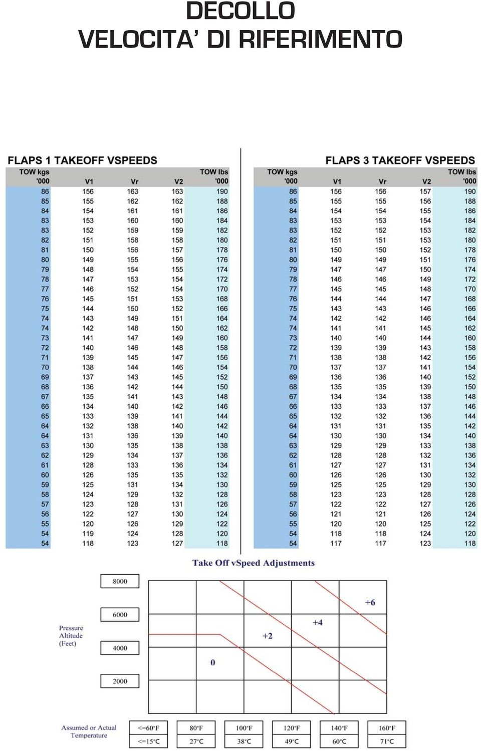
4 DECOLLO VELOCITA DI RIFERIMENTO
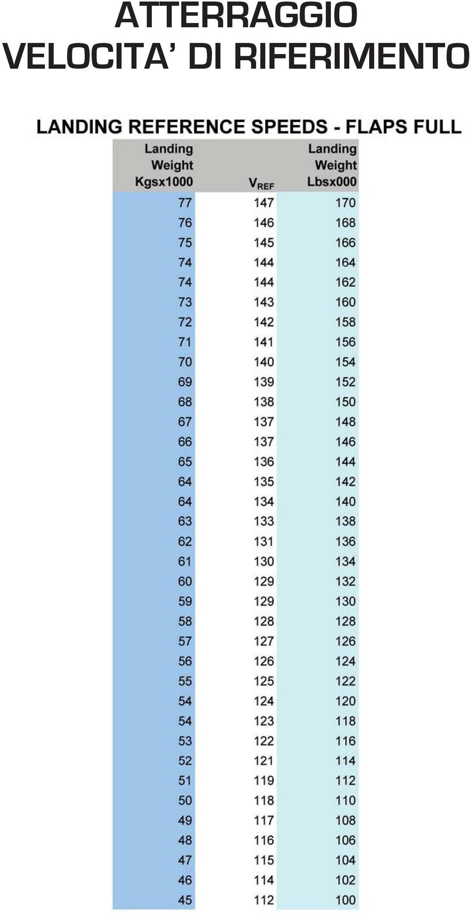
5 ATTERRAGGIO VELOCITA DI RIFERIMENTO
6

7 1 Normal Procedures Taxiing Nose-wheel steering is steer by wire and the steering hand-wheel is very sensitive. It provides a steering angle of up to 75 with an increase in the rate of turn in four separate bands. Inputs from the pilots hand-wheels are algebraically summed so this precludes handover of control whilst turning. Limited nose-wheel steering is also available using the rudder pedals. Take-Off Normal Procedure Think: Brakes Off, Watch On, Stick Forward, Power This subroutine should help you get started correctly! Release the brakes and start the stopwatch. Apply half forward side-stick; use the white cross on the PFD to gauge this control application. Set approximately 1.05 EPR or 50% N1. When both engines have stabilised, call setting power and advance the thrust levers to the FLEX or TOGA detent. At light weights and rear C of G positions, thrust should be applied with care to ensure nose-wheel adhesion. At 80kt gradually release the forward pressure on the side stick, achieving the neutral position by 100kt. Keep straight using nose-wheel steering via the rudder pedals. As the groundspeed increases the rudder becomes effective and the nosewheel steering input is progressively reduced to zero by 130kt. Crosswind Take-off For a crosswind greater than 20kt (or a tailwind): Apply full forward stick. Displace the white cross, into wind, by up to half its width. Set 1.05 EPR (50%), then when engines stabilised set 1.15 EPR (70%). Set Flex or TOGA by 40kt groundspeed. Expedited Take-Off For a rolling take-off use up to 1.03 EPR or 30% N1 until lined up. Rotation & Lift-Off At VR, rotate smoothly at 3º per second towards a pitch attitude of 15º then follow the flight director SRS pitch command. The normal attitude is 15º and should be achieved in about 5 seconds, so count to five as you rotate - start slowly as it is easier to increase the

8 rotation rate but more difficult to slow it down. The rotation rate tends to reduce as the attitude reaches 10, and additional side-stick back pressure is required to overcome this. Initial Climb Follow the SRS pitch demand (maximum is 18º) to the flap retraction altitude. The speed should stabilise at V2 + 10kt, but at light weights the aircraft may achieve a higher speed. Retract the landing gear when a positive climb is indicated on the VSI and radio altimeter. It is not necessary to apply the brakes as they are automatically applied when the gear handle is placed in the UP position. Flap Retraction The acceleration altitude may be specified but is normally 1000ft AAL. The flight director pitch mode changes to CLB and commands a pitch down. Select climb thrust as the LVR CLB prompt is displayed in the first FMA column. The normal take-off flap setting is flap 1; select flap zero as the aircraft accelerates through S speed. For take-offs with flap 2 or 3 retract the flaps on schedule: select flap 1 at F speed and flap zero at S speed. Early Turn Obstructions, or noise abatement procedures may dictate an early turn after take-off. Turn at the appropriate altitude and maintain the SRS attitude (V2 + 10kt) with flaps at the take-off setting. At acceleration altitude set climb power, accelerate and retract flaps on schedule. Flex Thrust A reduced thrust take-off results in lower EGTs and extends engine life. The maximum thrust reduction authorised is 25% below rated thrust and the resultant setting cannot be less than CLB. If conditions are encountered during the take-off where additional thrust is desired, such as temperature inversion or wind shear, select TOGA. Flex thrust is not permitted in certain circumstances. Eg. If stopping performance is significantly degraded, TOGA thrust is used to shorten the take-off run. A comprehensive list of restrictions for the use of flex thrust can be found in the Performance Manual, Take-off Section. FCU Handling FCU settings must be confirmed on the PFD. First look at the FCU, to confirm the correct selector, and then look at the PFD while making the actual selection. Check the PFD to ensure the correct bug or digit is being adjusted and confirm any change on the FMAs. This technique sounds simple enough but you will be surprised, initially, at how easy it is to make a mistake. Typically, for example, the aircraft continues in NAV when the crew think they have just selected HDG. The importance of checking the FMAs is routinely emphasised throughout conversion training - especially at times of high workload.

9 Control Laws Side-Stick Handling In Normal Law the side-stick is a load factor selector in pitch and a rate of roll selector in roll. The controls are very sensitive, so smoothly select the desired attitude and then release the pressure on the side-stick. The control laws will maintain 1G (within certain limits) without further input from the pilot. Most new pilots tend to over-control slightly until familiarity is gained. This over-controlling normally occurs at times of increased workload, but the tendency is easily overcome with a little practice. The side-sticks are not linked so movement of one side-stick is not felt by the other pilot. Inputs from both side-sticks are algebraically summed and so care must be taken not to move a side-stick (eg. whilst using the RT switch) when the other pilot is flying manually. With the autopilot engaged both side-sticks are locked in the neutral position. Applying sufficient force to move them will disengage the autopilot. High Speed Protection Normal Law With the autopilot engaged and auto-thrust active the system will not permit a Selected Speed greater than VMO/MMO. If an excessive speed (e.g. 380kt) is selected on the FCU, the aircraft will accelerate towards VMO/MMO and then thrust will automatically reduce to prevent an overspeed. If an overspeed occurs, perhaps because of a sudden unexpected increase in headwind, the autopilot will disconnect, auto-pitch trim is frozen and overspeed protection will activate. The auto-pilot disconnect aural warning will be masked by the ECAM overspeed warning. Spiral static stability is reduced to zero bank and the maximum bank angle is reduced to 45. As the speed increases, the side-stick nose-down authority is progressively reduced, and a permanent nose-up order is applied to aid recovery. To recover from an overspeed, reduce thrust and select (carefully) speedbrake. Alternate Law Above VMO / MMO the auto-pilot will disconnect and a simple nose up demand is introduced to avoid an excessive speed increase. This demand can be overridden by the pilot. High AOA Protection Normal Law As the aircraft enters the a protection region, back stick pressure is necessary to maintain attitude and auto-pitch trim ceases. Prior to reaching a-max, autothrust a-floor protection is activated and TOGA thrust is automatically applied. Alpha-floor protection should be backed up with the thrust levers. If the stick is moved fully aft the aircraft will stabilise at a-max. Lateral control is still effective but the maximum bank angle is limited to 45º. The aural stall warning is triggered at a-max + 4º, but since the system

10 limits alpha to a-max the warning should not activate in normal law. Releasing the back stick pressure completely will allow the speed to increase and stabilise at a-prot. Forward pressure is required to accelerate further. As speed increases away from a-prot, the FMA changes from ALPHA FLOOR to TOGA LOCK indicating that thrust is locked at TOGA. Once an acceptable speed is reached, deactivate TOGA LOCK by pressing the instinctive disconnect button on the thrust levers and move the thrust levers to select the desired thrust. In the landing configuration the deceleration is faster, acceleration in the recovery is slower and the speed range between VLS and the speed for a- max is smaller. During the recovery retracting the flaps from the landing position is not recommended until the speed is above VLS, as a greater altitude loss may occur. Note: Alpha Floor protection is an autothrust mode - not a flight control protection mode. Alternate Law During the initial deceleration, a side-stick input is not required to maintain the pitch attitude for level flight. The speed scale markings display only VLS and the stall warning speed: VSW (the black red barber s pole ). As the angle of attack increases, 5-10kt above the stall warning, a low speed stability term is introduced resulting in a gentle nose down pitching moment which can to be resisted using back pressure on the sidestick. Autothrust a-floor protection is inoperative. Eventually, the master warning and aural warnings will activate (crickets and STALL, STALL ). Recover at the stall warning by selecting TOGA thrust, maintain a pitch attitude for level flight and accelerate through VLS. Direct Law The control laws transition from alternate to direct when the landing gear is selected down and the crew are reminded to USE MAN PITCH TRIM. The aerodynamic static stability causes a nose-down pitching moment as the aircraft decelerates. This can be countered with back stick pressure. Autothrust a-floor protection is inoperative and stall warnings occur as in alternate law. During recovery, the pitching moment induced by the selection of TOGA thrust is not opposed by the control laws and must be resisted by an appropriate side-stick input. Recovery is conventional: select TOGA thrust and the pitch attitude for level flight. Normal Law Protections - Summary Load Factor Flap retracted: +2.5g / -1g Flap extended: +2.0g / 0g Pitch Load factor demand. Nose-Up: 30 Þ 25 at slow speed.

11 25 Þ 20 at slow speed in Config full. Nose Down: 15 F/D bars and FMA modes Off at: Up 25 / 13 Down. Roll Roll rate demand max 15 per sec. Normal - up to 33 bank angle with side-stick pressure - no auto-pitch trim. Maximum 67 2 green bars. F/D bars and A/P Off at 45 High AOA Protection Available from take-off to 100ft on the approach. Active at a prot top of the black/amber band. AOA is then proportional to side stick deflection. No auto-pitch trim. A/P disconnects at a prot + 1. a floor (TOGA) activated after a prot region penetrated. Max bank angle 45. Max AOA is a max top of the red band. If side-stick is released AOA returns to a prot and sticks. High Speed Protection Active at or above VMO 350kt / MMO.82M Auto-pitch trim frozen. A/P disconnects but aural warning masked by... ECAM red overspeed warning at VMO + 4kt. Activates at = 2 green bars at VMO + 6kt. Side-stick nose-down authority progressively reduced. Permanent pitch-up signal to aid recovery. Pilot can exceed VMO/MMO using forward side-stick pressure. Max bank angle 45. If the side-stick is released: aircraft pitches up and maintains zero bank angle. Flare Mode Active at 50ft attitude memorised. Auto-trim freezes at 50ft manual - 100ft autopilot. At 30ft pitch attitude reduced to 2 over 8 seconds. Alternate Law Protections- Summary Load Factor No change but this is the only protection available in Alternate Law without protections. Pitch No pitch protections amber crosses. Control response same as normal law load factor demand.
 activated after a prot region penetrated. Max bank angle 45. Max AOA is a max top of the red band. If side-stick is released AOA returns to a prot and sticks.")
12 Roll No roll protections amber crosses. Control response - control surface demand max 30.per sec Roll rate restricted by use of spoilers 4 and 5 only. A/P disconnects above 45 AOB. Low Speed Stability Available in Alternate Law with Protections. Black/Red barber s pole below Vs. Active at about Vs kt. Introduces a progressive nose down signal. Introduces bank-angle compensation to maintain max AOA in a turn. Audio: crickets + Voice: STALL. a floor inoperative. High Speed Stability Available in Alternate Law with Protections. Active above VMO. Introduces a nose-up pitch demand. Pilot can override. Conventional overspeed warning at VMO. Note: The ECAM STATUS message F/CTL ALTN LAW (PROT LOST) refers to the loss of Normal Law Protections and does not necessarily imply Alternate Law Without Protections. Confused? Blame the French. Direct Law - Summary Load Factor Not available. Pitch Control surface demand. No auto-pitch trim USE MAN PITCH TRIM. No protections. Roll As alternate. Low / High Speed Aural warnings as alternate. Alpha floor inoperative. Descent Preparation Complete the descent preparation as early as possible; on a very short

13 sector some aspects can be set-up prior to departure. The following sequence of FMGS programming is often referred to as FRPP. FLT PLN page: Complete a lateral revision at the destination and select the Approach and STAR, or VIA. Cross-check the STAR, Approach and Go-Around waypoints, and ensure that all altitude and speed constraints are relevant. RAD NAV page. Check the correct ILS has auto-tuned. Manually tune any NDBs or VORs as required. PERF pages. Check the descent speeds are as required. Enter the ATIS weather, the approach minima and the Go-around Aa. PROG page. Check Nav accuracy. Set the QNH on the standby altimeter and bug the Cat 1 or non-precision MDA. Bug VAPP on the standby ASI. Back-set the QNH on the EFIS control panel. Use the Descent Checklist aide-memoir to confirm all preparations are complete before starting the approach briefing. This will prompt you to consider the various items before you begin to speak and should result in a more efficient delivery. Descent Monitoring The FMGS is very sophisticated; however, experience shows that a simple, basic method is necessary to monitor the descent. Try to ensure that the FLT PLN distance-to-go is an accurate reflection of the ATC routing, and consider using the 3 times table - it is a useful tool for avoiding a rushed approach and for finessing the intermediate descent. Either: Multiply range by 3 to give desired altitude. Eg. 60 miles / feet - (slightly less than 3 ). Multiply height by 3 to give desired range. Eg feet / 54 miles - (slightly steeper than 3 ). The aim is to try to fly a 3 degree descent throughout the approach, avoiding level flight at intermediate flight levels - except as part of a planned, level deceleration. Alternatively, the required vertical speed to achieve a 3º descent angle can be estimated by halving the ground speed. Eg. Groundspeed 480kt, a vertical speed of 2400ft/min would be required. Using this method, adjustments can be made for a head or tailwind, and also for variations in descent speed. FMGS The FMGS will calculate all the descent parameters providing it has been correctly set up. It will insert a pseudo way point in the FLT PLN and, if in managed NAV, a descent arrow will be displayed on the ND. Managed DESCENT is only available in NAV mode and is achieved by pushing the altitude selector knob having first selected a lower altitude. Autothrust IDLE will be annunciated on the FMA and the Managed Speed is controlled by elevator, within a set range, to achieve the required FMGS vertical profile. If the computed descent profile is too steep a MORE DRAG message is displayed. Conversely, if the profile is too shallow to maintain the speed with idle thrust the autothrust will increase power and engage in SPEED or MACH mode. Above FL 310, if the aircraft is more than 500ft above the required

14 descent profile, the use of the DESCENT mode can lead to a MMO exceedance. In this case use OPEN DESCENT until the profile is regained or until the aircraft descends below FL 310. OPEN DESCENT is achieved by pulling the altitude selector knob having first selected a lower altitude. It results in idle thrust with speed controlled by elevator. The ECON descent speed is displayed on the PERF page of the FMGC. This is the Managed Speed and is determined by the cost index. It can be modified, but only prior to entering the descent phase; thereafter speed modifications can only be accomplished using Selected Speed. The ECON speed defaults to 250kt below 10,000 feet unless a vertical revision is made to delete or amend the speed restriction. Deviations from the programmed speed schedule can result in being too high (or low); use speedbrake or an increase in speed to regain the profile. Increase the Selected Speed gradually to avoid an excessive nose down pitch attitude. The descent is normally flown with autothrust engaged as this offers speed protection when capturing a pre-set altitude. Plan the descent to achieve green dot speed at 12 miles, or at about 8 miles out when making an abeam approach. A good cross check is to be at 10,000ft AAL, 33nm from the airport, with a maximum speed of 280kt decelerating towards 250kt. The following table gives approximate target Gates for still air with engine anti-ice OFF. Distance Height Speed Config max Clean Clean or Green Dot Flap or S speed Flap or F speed Flap 2 or 3 + Gear Descent In Icing Conditions The use of engine anti-ice, and the increase in idle thrust that is associated with it, will increase the descent distance required. Engine icing often forms when unexpected and can occur when there is no evidence of icing on the ice detector. Once ice has formed, an increasing accumulation can occur rapidly. The engine anti-ice system should be turned on whenever visible moisture is present, or the visibility is 1500m or below and the TAT is at or below +10ºC. Engine anti-ice may be turned off during the climb and cruise when the SAT is below -40 C. Deceleration At idle thrust in level flight, deceleration from VMO to 280kt takes about 1 minute, and from 280kt to 210kt takes about 1minute 10 seconds. Using speedbrakes to aid deceleration will reduce these times and distances by approximately 40%. Speed Reduction Time Distance mins 10 secs 10 nm min 6 nm min 10 secs 4 nm Speedbrake extension causes a pitch up which is useful in containing an overspeed excursion; however, rapid retraction causes a pitch down and

15 can cause a small altitude bust if retraction takes place in ALT* during level off after a descent. All speedbrake selections should be made slowly to avoid rapid pitch changes and for passenger comfort. Holding Complete a lateral revision at the appropriate way point to insert a hold. Check the parameters displayed on the HOLD page and amend if necessary. Standard ICAO timing is achieved by checking or inserting 1 or 1.5 min in the appropriate field. A gross error check, however, should still be made by timing the hold using the stopwatch. Once inserted, the aircraft will enter and remain in the hold. The FMGS will compute the hold entry using a variable bank angle to pick up the holding axis. The ND depicts the race track pattern with the inbound and outbound turns drawn for still air but takes no account of the variable bank angle employed. The aircraft symbol may not follow the holding pattern as drawn if there is a significant cross-axis wind component. If the cross-axis wind component exceeds 40kt, the aircraft will not immediately pick up the holding axis on completion of the inbound turn. If the crosswind component exceeds kt, the FMGS may not be able to keep the aircraft within the protected holding area, and pilot intervention will be needed. To exit use the Immediate Exit prompt, or perform a Direct To, or select HDG. It is important to ensure that the Hold is cleared from the FMGS Flight Plan; if it is not the waypoints will not sequence correctly and the Go-around Flight Plan will be unavailable. The normal holding speed is 5-10kt above green dot and the aircraft configuration should be clean. As the aircraft approaches the holding fix in NAV mode, the Managed Speed target will reduce from the descent speed to green dot and the aircraft will decelerate. However, on leaving the hold, if the FMGS is still in the PERF DES phase (ie. approach not activated), the speed target will jump to the previous descent speed. If this is not desired activate the approach or change to Selected Speed. This can be done at any time prior to or during the hold. Intermediate Approach Using Managed Speed, the initial approach is flown clean at Green Dot. Select Flap 1 on base leg and reduce to S speed. For further deceleration select Flap 2 and slow to F speed. Remember that these are procedural speeds rather than minimum speeds. The minimum speed for the configuration is always displayed as VLS on the PFD speed scale. Config Procedural Speed Minimum Speed Clean Green dot VLS Flap 1 S speed VLS Flap 2 & 3 F speed VLS Flap Full VAPP VLS To enable automatic deceleration with configuration change, activate the approach on the PERF page, and ensure that Managed Speed is selected on the FCU. The speed will then re-datum automatically according to the table above. The magenta speed target bug will be at VAPP and may not be visible until the speed has reduced. If ATC requires speed control use Selected Speed and set the required speed on the FCU.

16 The use of speedbrakes on the approach with flaps extended up to Flap 3 is permitted but not recommended as this causes an unwanted increase in VLS. The recommended method, to achieve greater deceleration, is to extend the landing gear earlier than normal. Speedbrake is inhibited with Flap Full. If the approach pattern requires a downwind leg select NAV ROSE to enable the runway and final approach to remain in view. At other times most pilots use NAV ARC, gradually decreasing the selected range throughout the approach. Select the ILS display using the push-button on the EFIS control panel. The ILS ident and DME are shown at the bottom left of the PFD. Select VOR/ADF needles as required, and display a VOR DME range if required by the procedure. When cleared to intercept the localiser arm LOC on the FCU. When cleared for the ILS approach arm APP and engage the second autopilot. At glideslope capture set the goaround altitude on the FCU and check the TO waypoint is appropriate on the ND. Go Around During a go-around, as the NHP raises the landing gear he announces the FMA modes: TOGA, SRS, GA TRK The aircraft will maintain the GA TRK until the FCU heading knob is pushed for NAV or pulled for HDG. If NAV is available the FMGS will guide the aircraft along the FLT PLN, but only if the waypoints have sequenced correctly. Obviously, it is essential that the correct go-around altitude has been selected on the FCU. From an Unstable Approach If a go-around is initiated at, for example 1000ft/160kt, additional considerations apply. TOGA power should be selected as this action engages Go-Around mode and ensures NAV will be available throughout the missed approach. However, it may be prudent to re-select CLB power almost immediately; this will provide adequate power, re-activate autothrust and help prevent a possible flap overspeed. From Level Flight A go-around may need to be initiated from ALT mode, for example at 3000ft when the aircraft has failed to capture the glideslope and is now too high. Selecting TOGA power will engage go-around mode, but this may not be the best option as the aircraft will commence a climb away from the cleared altitude. This could cause obvious problems in a busy ATC environment. Without Selecting TOGA The FMGS section of the Flying Manual states that performing a goaround without selecting TOGA will sequence the destination and erase the active flight plan when flying over or abeam (less than 7 miles) the airport. If this occurs activate the secondary flight plan at an opportune moment. Alternatively, enter a waypoint, perform a lateral revision and insert a new destination.

17 Flight Director The flight directors automatically re-engage during a go-around and the autothrust will re-arm even though it may have been disengaged for the approach. Thereafter, it will activate when the thrust levers are set to the climb detent, just as it does on a normal take-off. As the go-around altitude is captured thrust will reduce to maintain the speed. Decelerated ILS Approach Managed Speed Judgement of the vertical profile and deceleration is one of the more difficult aspects of the final approach. When ATC speed control is not required use Managed Speed. Glide-slope interception is achieved, preferably in a continuous descent, in Config 1 at S speed. Flap 2, Landing Gear, Flap 3 and Full are selected in sequence in order to achieve a stabilised approach by 1000ft. Remember that the Flying Manual requires Flap 2 and Landing Gear extension to be accomplished by 2000ft AAL. The precise timing of the configuration changes, and thus the rate of deceleration, can be controlled by the crew to suit the local met conditions. Selected Speed ATC often require some form of speed control, and most AERAD booklets give details of the likely speed profile. Therefore, it is quite normal for pilots to initiate the descent in Managed Speed and then change to Selected during the intermediate approach in order to meet these requirements. Thereafter, it may not be appropriate to re-select Managed Speed until Flap 3 or Full is selected during the landing checklist. Speed control is therefore an important consideration and one that can be easily overlooked - even in good weather. Example It is common practice for ATC to request 160 to 4 DME or 170 to the marker. So how can this be achieved? The technique to be used is basically dependant on the presence or absence of a headwind. Headwind Consider using Selected Speed 160kt and, when appropriate, select flap 2 and lower the landing gear as normal. Then at 4.5 DME (1500ft) select Flap 3 and change to Managed Speed. Observe the deceleration and select Flap Full in time to achieve the stable approach criteria by 1000ft radio. Tailwind In light winds, or a tailwind, the aircraft might stabilise on the glideslope at say 10 miles, 3200ft Flap 1, at 205kt. Simply plan to lower the landing gear early, at say 2800ft, in order to achieve a deceleration to S speed (eg 180kt) by 2500ft and guarantee a stable approach. Alternatively if ATC require 180kt at 10 DME extend the landing gear without delay and use Selected Speed. The landing gear is far more effective than speedbrake in stabilising the approach. The Flying Manual states: the use of speedbrake will cause an unwanted increase in VLS. Good judgement and experience are required, so early in your training be conservative and do not hesitate to refuse an instruction to maintain

18 170kt to 4 DME. Decide at the briefing stage what you can achieve, eg. 160 to 4.5 DME, and tell ATC. Furthermore, beware of foot-notes on the THALES ILS chart which point out that the DME reads 1.1 mile at touchdown. If the non-landing pilot misjudges the deceleration the speed may exceed the VAPP target at 1000ft radio and a go-around must be considered. The landing pilot might then announce: considering a go-around. This would alert both pilots so that if the stabilised criteria are not met by 500ft a mandatory go-around would not come as a surprise. Automatic Non Precision Final Approach Non precision approaches using Managed guidance (APP NAV/FINAL) are not permitted at present. Therefore, the following procedures specify the use of Selected vertical and horizontal guidance, and Managed Speed. The recommended technique is to fly an automatic, speed stabilised approach using the FPV and autothrust. NDB Check the FMGS Arrival page and select the NDB approach if available. If there is no NDB approach in the data base select the ILS approach if the procedure and go-around are similar. Alternatively select RW but note that a go-around profile will not be available. Tune the NDB and display the needles using the NAV ARC or NAV ROSE display. NAV ROSE is normally used during the initial approach, whilst the NAV ARC display gives an expanded compass segment enabling precise monitoring on the inbound track. The map range should be adjusted to prevent clutter at the top of the ND. For an NDB/DME approach, enter the DME ident or frequency in a VOR field, identify and display the DME on the ND by selecting the respective needle to VOR. Only one needle will then be available for NDB tracking. Alternatively, enter the DME frequency in the ILS field and display the range on the ND by selecting ILS on the EFIS control panel. VOR Check the FMGS Arrival page and select the VOR approach if available. If there is no VOR approach in the data base select the ILS approach if the procedure and go-around are similar. Alternatively select RW but note that a go-around profile will not be available. The VORs should auto-tune provided a VOR approach has been selected. Alternatively, manually tune both VORs, enter the inbound course on the NAV RAD page, identify normally and display the needles using ROSE VOR, NAV ARC or NAV ROSE. Localiser Set-up the FMGS for a normal ILS approach. Select the ILS display on the PFD and identify. Deselect the GPWS G/S mode. Select either ROSE ILS, NAV ARC or NAV ROSE. Vertical Profile The final approach track should be intercepted at S speed, flap 1. Aim to
 are not permitted at present.")
19 select flap 2 and landing gear at approximately 3 miles prior to the final descent point. The aircraft should be in the landing configuration and speed stabilised at VAPP approximately 1 mile prior to commencing the descent. (For single-engine approaches Flap Full is selected during the final descent) To commence descent simply turn the FPA knob to select the desired FPA and PULL. This selection should be made.3 nm prior to the descent point to allow time for the autopilot to respond. To avoid unwanted ALT capture do not select a lower altitude on the FCU. The Go-Around altitude should be pre-set on the FCU when the aircraft has descended below Go-Around altitude. Note that 0.5 FPA equates to approximately 100 feet per minute rate of descent and to vary the profile remember that 1 achieves a 100 feet per mile adjustment. Eg. if 100 feet high select 4 to achieve the correct glideslope in 1 nm. Horizontal Profile For NDB, VOR, or radar approaches, make appropriate TRK selections on the FCU to intercept and maintain the inbound course. For a LOCALISER approach, arm LOC on the FCU and monitor capture. MDA Or When Visual If the required visual references are obtained before MDA control handover takes place. The autopilot should be disconnected and the flight directors selected OFF. Manual Non-Precision Approach Flight Director Off A Non-precision approach may be flown without using the flight director or autopilot. The FMGS set-up is the same. Vertical Profile Select pitch attitudes on the PFD referring to the fixed aircraft symbol in the conventional way. Check the achieved FPA (indicated by the FPV) and vertical speed, then adjust pitch attitude as necessary. Try to resist the temptation to chase the FPV and VSI; remember they are performance instruments. FPA selections are not made on the FCU. Horizontal Profile The FCU selected track is displayed by a blue index on the PFD horizon line. It is selected to the inbound course for the final approach and is used as a track reference. The correct inbound track is maintained by positioning the FPV with reference to the blue TRK index. When the FPV is aligned with the TRK index the aircraft will maintain the track selected on the FCU. Naturally it is necessary to ensure that the aircraft is established on the correct QDM before aligning the FPV and TRK index. Failure to do so simply results in the aircraft paralleling the desired track. MDA Or When Visual For the visual segment consider selecting the FCU track to the runway centreline if this differs from the inbound course.

20 Circling Approach A circling approach is an IFR approach (either precision or non-precision) followed by a visual circuit. Each circling situation is different because of variables such as runway layout, final approach track, and meteorological conditions. A single procedure will not cater for all circumstances. An appropriate time for handover of control should be discussed and should take account of the circuit direction. Consideration should be given to the appropriate response when the decide call is made. Also, the Missed Approach Point (MAP) has particular significance on this type of approach. FMGS Set-Up The FMGS set-up is not ideal as the landing runway is not the same as that used for the instrument approach. Furthermore, in the event of a goaround the missed approach procedure for the instrument approach must be followed. The recommended compromise is as follows: Enter the instrument approach in the primary flight plan. Complete the PERF APPR page - enter the ATIS etc. Copy the flight plan and modify the secondary - enter the landing runway. If desired, construct waypoints in the secondary flight plan to assist orientation for the circling manoeuvre. For example for BRU RW02: EBBR02/200/2, (PBD01) PBD01/290/2, (PBD02) These are two very useful waypoints depicting the end of a downwind leg and a point on short final. Initial Approach The initial instrument approach should be flown in Flap 3 (Flap 2 single engine) with the gear down. If the autopilot is in use the flight directors should be on. If flying an ILS to circle, an early selection of TRK/FPA during the ILS may be preferred. The go-around altitude should be set in the FCU as normal. About 100 feet above the circling minima select (push) FPA zero on the FCU. The aircraft must be levelled at or above the MDA. It is not permissible to descend below the MDA until the aircraft is in a position to commence a descent to the landing threshold at the normal rate on a 3 flight-path. If the required visual references are not achieved at MDA go-around immediately. The references are described in FCO 752: sufficient visual reference with the terrain and either the approach lights or the runway must be continuously in view. At MDA there is no immediate requirement to disconnect the autopilot, or turn off the flight directors, or handover control. The autopilot may remain engaged until the final descent when it must be disconnected by 100 feet below MDA; the flight directors should then be switched off. JAROPS subpart E stipulates that the instrument approach track should be maintained until the crew estimate that: The required visual references can be maintained throughout the procedure.
 has particular significance on this type of approach.")
21 The aircraft is within the circling area. The aircraft s position in relation to the runway can be determined visually. If these conditions are not met by the MAP a missed approach must be carried out. Circling Manoeuvre Initially, display but do not activate the secondary flight plan. This is achieved by pressing the SEC F-PLN key on each MCDU; the secondary route is then displayed in white. The primary route remains active (green) and thus the instrument go-around procedure remains available. When downwind, and when a landing is considered assured, activate the secondary flight plan. The managed speed target will now be correct for the landing runway. Alternatively, if it is considered more prudent to retain the go-around profile do not activate the secondary but remember that the managed approach speed for the landing runway will be wrong as the incorrect wind component will be used to calculate VAPP and the VAPP Target. Therefore use Selected Speed and calculate manually the correct VAPP adding wind increments as necessary. The low visibility pattern in the Flying Manual suggests an initial turn through 45 for 30 seconds followed by a downwind leg, extending beyond the landing threshold by 20 secs per 500ft. This is only a guide and must be adapted for the actual conditions. Experience in the simulator suggests that the waypoints on the ND are very useful for confirming lateral separation from the runway. With NAV ROSE and minimum range displayed, comfortable separation is achieved when the runway symbol is just inside the 2.5 nm range circle. Use all available aids, eg. Nav Display, VOR or NDB, to assist your visual judgement of when to turn onto base leg. Care must be taken to remain within the circling radius. When turning onto final, the aircraft should be fully configured at the correct speed and comply with the stable approach criteria. If the waypoints have cycled correctly the magenta vertical deviation symbol on the PFD may be used to assist judgement of the final descent. Go Around If at any time visual reference is lost a Go-around must be flown by entering a climbing turn towards the runway and establishing on the missed approach procedure specified for the instrument approach. Different patterns will be required depending on the aircraft s position at the time the Go-around was commenced; however, it may be prudent to clarify precise requirements with ATC. Landing Technique Flare & Touchdown The landing gear should cross the runway threshold at approximately 50ft. Go-around if threshold clearance is doubtful. Just before the flare make a conscious effort to look towards the far end of the runway and avoid any temptation to fixate on the touchdown zone. This will assist in
22 determining the flare point. Under normal stable approach conditions, at 30 ft hold the attitude, close the thrust levers and commence the flare by 20ft. Most initial landing attempts in the simulator using this technique result in a slightly firm touchdown, and trainees can be re-assured that this is not unusual! However resist the temptation to over-compensate - only a small side-stick input is required and flaring at 50ft is not the solution. During your first attempts concentrate on using the correct technique and do not be put off if your landings are firmer than you would like. After the initial rotation there should be little additional increase in pitch attitude to complete the flare, back pressure is only required to counter the nose down effect of the flight control flare law. This mode mimics the normal response of a conventional aircraft. Do not allow the aircraft to float but fly the aircraft onto the runway. After main gear contact gently lower the nose using the side stick. The aircraft does not exhibit a pitch up tendency after touchdown when the ground spoilers deploy; however, a reduction in the nose down pitch rate is evident. Application of autobrakes after main gear touchdown increases the nose down forces but can be easily countered by elevator inputs. If a bounce occurs, hold or re-establish a normal landing attitude. Thrust need not be added for a shallow bounce or skip. If a high, hard, bounce occurs go-around immediately. A second touchdown may occur during the go-around. Do not retract the landing gear until a positive rate of climb is established. Crosswind Landing Position the aircraft on the extended runway centre line with drift applied. In conditions of strong crosswinds, because of the length of the aircraft, the pilot will be positioned on the upwind side of the centre line. In the flare, progressively apply rudder to visually align the aircraft heading with the runway. At the same time apply sufficient bank to maintain the runway centreline. Remember that a sustained lateral sidestick input will produce a roll-rate demand and not a constant bank angle, so once the desired bank angle is achieved centre the side-stick. Touchdown should be on the into-wind landing gear. After touchdown keep a little into-wind side stick to help prevent any subsequent wing lift. Landing Roll For maximum effectiveness use autobrakes or commence manual braking and apply reverse thrust at main wheel touchdown Apply the brakes smoothly with steadily increasing pedal pressure as required for runway condition, distance available or for a desired turn off point. Maintain deceleration rate with constant or increasing brake pressure as required until stopped or desired taxi speed is reached. Excessive brake modulation should be avoided for passenger comfort and to minimise brake wear. Rudder control and rudder pedal steering are sufficient for maintaining directional control during the roll out. As it is difficult to slide feet up the rudder pedals in crosswinds, feet should be positioned with the toes at the top of the pedals prior to touchdown. Steering after touchdown is
23 accomplished with the heels and braking with the toes. Wind Corrections - Final Approach The approach speed, VAPP target, is continuously adjusted to take into account the actual wind conditions. It is therefore recommended that Managed Speed is used in gusty conditions. However the system may demand speeds in excess of VFE; in this case use a Selected Speed until below 1,000ft AAL. The FMGS compares the actual wind conditions (at the aircraft) with the ATIS wind entered on the PERF APPR page. If the actual headwind at the current altitude is greater than that entered in the FMGS, the VAPP target on the PFD will increase. However, if the headwind is less than reported or if an unexpected tailwind is encountered the VAPP target is limited to the VAPP calculated on the PERF APPR page When the wind is close to 90 across the runway an increment will not be added automatically. Consider increasing VAPP by up to VLS + 15kt to give a comfortable margin.
24 EMERGENCY PROCEDURES
25 EMERGENCY PROCEDURES OVERWEIGHT LANDING Maximum Certified Landing Weights: /Airbus A = 61,000kgs/ Airbus A320 = 66,000kgs/ Airbus A321 = 77,800kgs. BAV Airbus Captains may elect to land at a weight greater than the certified maximum landing weight for Airbus type by using emergency authority when a condition or combination of conditions makes an overw landing a prudent course of action. If an overweight landing is to be performed ensure adequate runway length and go-around capability exists. Make a normal approach and landing. Overweight landings impos larger than normal stresses on the airplane. Avoid a high sink rate on touchdown and avoid excessive sid loads on rollout. Automatic landing is certified up to MLW, but has been demonstrated in flight up to MTOW. In determinin best course of action, the flight crew may consider the option to perform an automatic landing provided th runway is approved for automatic landing Landing Configuration. Full Selected Speed. Use Landing Distance. Check Packs. Off or Supplied By APU Selecting packs off (or supplied by APU) will increase the maximum thrust available in the event of a Go-Around. Landing Weight. kgs For weights greater than 70000kg S speed is greater than VFE CONF 2 (200 KNOTS). Consequently the crew must select on FCU a speed below 200 knots before setting FLAPS 2. When in FLAPS 2 crew can use managed speed again. In the final stages of approach: Target Speed. VLS Reduce speed to reach VLS at runway threshold. Touch down as smoothly as possible (maximum V/S at touchdown 360 ft/min). At main landing gear touchdown: Reverse Thrust. Max After nose wheel touchdown: Brakes. Apply as necessary Maximum braking may be used after nosewheel touchdown but, if landing distance permits, delay or reduce braking to take full benefit of the available runway length. Landing Complete: Brake Fans. On Be prepared for tyre deflation if temperatures exceed C
26 EMERGENCY PROCEDURES ENGINE RELIGHT IN FLIGHT AUTOPILOT. Engage AUTOTHRUST. Disconnect GREEN DOT SPEED. Select THR LEVER (affected). Idle THRLEVER(unaffected). FLX/MCT Pilots using the PSS version will not be able to move the affected thrust lever to Idle unless they have unsynchronized the thrust levers first. If this has not been done both thrust levers should be moved to the FLX/MCT gate. MAX ALTITUDE. See Chart OPEN DESCENT. Initiate ENG MASTER (affected). Off MAN START pushbutton. Off Auto start is recommended in flight. Be aware that, contrary to auto start on ground, the crew must take appropriate action in case of abnormal start. ENG MODE SEL. IGN X BLEED. Open Knob to the right of APU Bleed on overhead panel WING A.ICE (for starter assist). Off ENG MASTER (affected). On Monitor N2. If uncertain about engine relight, move thrust lever forward and check engine response When idle reached: Pilots using the PSS version will notice that as the thrust levers are in the FLX/MCT gate the affected engine will spool up beyond idle to MCT thrust. This is not a problem and the items below can still be performed normally once the engine has spooled up. ENG MODE SEL. Norm TCAS MODE SEL. Check TA/RA XBLEED. Auto THR LEVERS. CLB AUTOTHRUST. Engage XBLEED. Auto If no relight: ENG MASTER (affected). Off Wait 30 seconds before attempting a new start (to drain the engine)
27 EMERGENCY PROCEDURES REJECTED TAKEOFF BAV Airbus pilots must clearly understand that any decision to reject a takeoff must be made so brake application is made by, not after, V 1. Captains must develop a mind set which recognizes that any decision to abort from a speed near V 1 is a decision that the airplane cannot fly, rather than a decision that the airplane can stop. A decision to stop should be made only if the failure involved would impair the ability of the airplane to be safely flown. Conditions warranting a stop near V 1 are an engine failure or a malfunction where there is doubt that the airplane will fly. The following procedures for an RTO should be carried out from recall, not by reference at the time to this checklist: Call Stop Stop. Accomplish Throttles. Full Reverse Use maximum allowable thrust consistent with directional control. Autobrakes. Verify Verify autobrake application. Auto-braking is the primary method of brake application if the groundspeed is above 72 knots. However the Captain must be prepared to use manual braking in the event of autobrake failure or premature disengagement. Ground Spoilers. Verify Verify ground spoiler extension if the RTO was initiated above 72 knots. ATC. Notify Notify air traffic control of the RTO and include the runway where the RTO occurred. Follow ATC taxi instructions. Consider requesting fire equipment for an RTO above 80 knots. After Landing Checks. Accomplish
28 EMERGENCY PROCEDURES ENGINE FAILURE AFTER V1 NB.IntheeventofanenginefailurebetweenV 1 and V 2 in the PSS version of the Airbus, pilots should be aware that continued flight is unlikely. If an engine fails after the aircraft passes V 1 the takeoff must be continued. Use rudder to stay on the runway extended centerline. At V R rotate the aircraft smoothly to a pitch rate of 12.5 degrees (or 10 degrees if thrust remains at FLEX), then follow the Speed Reference System (SRS) after the FD bar has stabilized. When airborne with a positive rate of climb select gear up. Useruddertopreventyaw. Consider use of TOGA thrust. At 400 feet select autopilot on. If the engine failure occurs between V1 and V2 the initial target speed is V2. If the failure occurs between V2 and V2+10 the target speed is the speed reached at the time of failure. If engine failur occurs at V2+10 or higher the target speed is V2+10. At acceleration height level off and allow speed to increase. At F speed select Conf 1. At S Speed select Conf 0. At green dot speed resume the climb using MCT and maintain green dot speed
29 CHECKLIST BEFORE START Briefing Complete Checked BEFORE START Briefing Complete Checked Parking Brake Set Packs 1 and 2 Off Battery 1 and 2 On APU Bleed On APU Master On Flap Open on Lower ECAM Checked APU Start On External Power Avail Packs 1 and 2 On Engine 1 and 2 Master Off Mode select Norm Flaps Zero Ground Spoilers Ret Flight Director On BEFORE PUSHBACK Doors Closed Seat Belts Sign On Cabin Secure Beacon On Parking Brakes Released START Fuel Pumps Auto & On Mode select Ign/Start Engine Master 2 On Engine Master 1 On AFTER START Engines running and stable Checked Mode select Norm Engine Anti Ice As Reqd BEFORE TAXI Strobes On Nav and Logo Lights On Wing and Taxi lights On TAXI CHECKLIST Squawk Mode C Flaps Set xxxx Ground Spoilers Armed Autobrake Max Initial Altitude Set xxxx Altimeter Set xxxx Trim Set xxxx Take Off Config No Blue Briefing Reviewed BEFORE TAKEOFF Landing Lights On Transponder Set AFTER TAKEOFF Gear Up Checked Speed Brakes Ret APU Bleed Off APU Master CLIMB Autopilot 1 On Landing Lights Off Taxi Lights Off Autobrake Off Seat Belt Sign Off Altimeter Set xxxx DESCENT (FL100) Briefing Complete Checked Autobrake Set xxxx ILS on PFD On Seat Belt Signs On Landing Lights On RAD/NAV ILS Set xxxx Approach Phase Data Entered
MEMO AIRBUS A319/A320/A321. SOP / Flow Pattern
 MEMO AIRBUS A319/A320/A321 SOP / Flow Pattern F/O side only ( or ) A320 Flow Pattern SOP Visual Pattern Engine Out Memory Items Emergency procedures Laurent ALAPHILIPPE Page 1/18 Année 2011 Summary Memo
B777. Automatic Flight DO NOT USE FOR FLIGHT
 B777 Automatic Flight DO NOT USE FOR FLIGHT 4.10 Automatic Flight-Controls and Indicators Mode Control Panel (MCP) A/T ARM L R IAS MACH HDG TRK V/S FPA ALTITUDE A/P F/D ON OFF CLB CON IAS LNAV VNAV AUTO
ENGINE FIRE / SEVERE DAMAGE / SEPARATION ON TAKEOFF
 ENGINE FIRE / SEVERE DAMAGE / SEPARATION ON TAKEOFF According to RYANAIR Procedures PF PM REMARKS Control the aircraft (FULL T/O thrust can be manually selected) Announce «ENGINE FAILURE» or «ENGINE FIRE»
Cessna 172SP & NAV III Maneuvers Checklist
 Cessna 172SP & NAV III Maneuvers Checklist Introduction Power Settings This document is intended to introduce to you the standard method of performing maneuvers in Sunair Aviation s Cessna 172SP and NAV
2014 NIFA CRM Contestant Briefing Guide San Diego, California
 2014 NIFA CRM Contestant Briefing Guide San Diego, California Region 2 SAFECON 2014 November 12 15 This document supports the 2014 NIFA Collegiate Cockpit Resource Management Simulation and is not for
This is the third of a series of Atlantic Sun Airways CAT B pilot procedures and checklists for our fleet. Use them with good judgment.
 This is the third of a series of Atlantic Sun Airways CAT B pilot procedures and checklists for our fleet. Use them with good judgment. Dimensions: Span 107 ft 10 in Length 147 ft 10 in Height 29ft 7 in
This is the fourth of a series of Atlantic Sun Airways CAT B pilot procedures and checklists for our fleet. Use them with good judgment.
 This is the fourth of a series of Atlantic Sun Airways CAT B pilot procedures and checklists for our fleet. Use them with good judgment. Dimensions: Wing Span: 112 ft 7 in Length: 129 ft 6 in Height: 41
BOMBARDIER CRJ700. Bombardier CRJ700 Aircraft Reference
 Bombardier CRJ700 Aircraft Reference V 1 Takeoff Decision Speed, dry runway 50,000 lbs, (flaps 8) 144 KIAS 50,000 lbs, (flaps 20) 134 KIAS V R Rotation Speed, dry runway 50,000 lbs, (flaps 8) 144 KIAS
TAXI, TAKEOFF, CLIMB, CRUISE, DESCENT & LANDING
 OPERATIONS MANUAL FLT CREW TRAINING COMMERCIAL LEVEL SIMULATIONS TAXI, TAKEOFF, CLIMB, CRUISE, DESCENT & LANDING Commercial Level Simulations www.commerciallevel.com 1 Disclaimer This manual is not provided
General Characteristics
 This is the third of a series of Atlantic Sun Airways CAT C pilot procedures and checklists for our fleet. Use them with good judgment. Note, the start procedures may vary from FS9 Panel to Panel. However
Compiled by Matt Zagoren
 The information provided in this document is to be used during simulated flight only and is not intended to be used in real life. Attention VA's - you may post this file on your site for download. Please
Automation at Odds. A 737 stalled when a radio altimeter malfunction caused the autothrottle and autopilot to diverge during an approach to Schiphol.
 Automation at Odds The pilots of a Boeing 737-800 did not heed indications of a significant decrease in airspeed until the stick shaker activated on final approach to Runway 18R at Amsterdam (Netherlands)
This section includes performance data on the King Air B200. Information consists of:
 King Air B200 POH Pilot's Operating Handbook: This section includes performance data on the King Air B200. Information consists of: 1. Critical Airspeeds 2. Operating NOTAMS 3. Fuel Loading Formula Checklists:
Cessna 172S. Flight Training Standardization Guide REVISION: ORIGINAL
 Cessna 172S Flight Training Standardization Guide REVISION: ORIGINAL Contents Purpose... 4 Normal and Crosswind Takeoff and Climb... 5 Normal and Crosswind Landing... 6 Soft Field Takeoff and Climb...
Light Sport West Standard Flight Training Procedures for N110GX (Remos GX, 100 H.P.)
") Light Sport West Standard Flight Training Procedures for N110GX (Remos GX, 100 H.P.) Welcome to Light Sport West! Thank you for giving us the opportunity to provide all of your flight training needs. Our
Light Sport West Standard Flight Training Procedures for N110GX (Remos GX, 100 H.P.) Welcome to Light Sport West! Thank you for giving us the opportunity to provide all of your flight training needs. Our
G1000 Search Patterns. National Emergency Services Academy Mission Aircrew School (June 2013 Rev D)
") G1000 Search Patterns National Emergency Services Academy Mission Aircrew School (June 2013 Rev D) Standardized Visual Search Pattern method Visual search pattern techniques include: Minimum # of user
G1000 Search Patterns National Emergency Services Academy Mission Aircrew School (June 2013 Rev D) Standardized Visual Search Pattern method Visual search pattern techniques include: Minimum # of user
Revision Number Revision Date Insertion Date/Initials 1 st Ed. Feb 01, 00 2 nd Ed. Jun 24, 02 3rd Ed. Feb 15, 07
 List of Effective Pages * Asterisk indicates pages changed, added, or deleted by current revision. Retain this record in front of handbook. Upon receipt of a Record of Revisions revision, insert changes
B777. Landing Gear DO NOT USE FOR FLIGHT
 B777 Landing Gear DO NOT USE FOR FLIGHT Introduction The airplane has two main landing gear and a single nose gear. The nose gear is a conventional steerable two wheel unit. Each main gear has six wheels
FLIGHT TRAINING (AEROPLANE) BASED ON JAR FCL - PPL(A) FLIGHT INSTRUCTION Syllabus
 BASED ON JAR FCL - PPL(A) FLIGHT INSTRUCTION Syllabus") FLIGHT TRAINING (AEROPLANE) BASED ON JAR FCL - PPL(A) FLIGHT INSTRUCTION Syllabus for MARSPOLAR, DUBAI UAE Exercise 1 Familiarisation with the aeroplane characteristics of the aeroplane cockpit layout
FLIGHT TRAINING (AEROPLANE) BASED ON JAR FCL - PPL(A) FLIGHT INSTRUCTION Syllabus for MARSPOLAR, DUBAI UAE Exercise 1 Familiarisation with the aeroplane characteristics of the aeroplane cockpit layout
09 FLIGHT MANAGEMENT, NAVIGATION
 Course overview N E X T G E N E R A T I O N Airplane General Air Systems Warning Systems, Communications, Ice & Rain Protection Electrical Engines, APU, Fuel System Hydraulics, Flight Controls, Landing
The SeaRey - An Introduction
 The SeaRey - An Introduction Welcome to the beautiful Progressive Aerodyne SeaRey. The SeaRey is a very special aircraft. Created by a small team of engineers the SeaRey is perhaps the ultimate kit built
S-Tec System Thirty Autopilot
 Cirrus Design Section 9 Pilot s Operating Handbook and FAA Approved Airplane Flight Manual Supplement for S-Tec System Thirty Autopilot When the S-Tec System Thirty Autopilot is installed in the Cirrus
FLIGHT CONTROLS 1. GENERAL 2. MAIN COMPONENTS AND SUBSYSTEMS ROLL CONTROL. Smartcockpit.com BOEING 737 SYSTEMS REVIEW Page 1
 Smartcockpit.com BOEING 737 SYSTEMS REVIEW Page 1 FLIGHT CONTROLS 1. GENERAL The primary flight controls, ailerons, elevators and rudders, are hydraulically powered. Hydraulic power is provided from hydraulic
BE76 Beechcraft Duchess Maneuvers Checklist
 BE76 Beechcraft Duchess Maneuvers Checklist Introduction Power Settings This document is intended to introduce to you the standard method of performing maneuvers in Sunair Aviation s Beechcraft Duchess
Flight Operations Briefing Notes
 Flight Operations Briefing Note I Introduction Operations in crosswind conditions require strict adherence to applicable crosswind limitations or maximum recommended crosswind values, operational recommendations
Aviation Safety Prize ecfi Tasks
 2008 NASA "The PAV Challenge" Aviation Safety Prize ecfi Tasks The Aviation Safety Prize (ASP) will be based upon a set of defined tasks that can be flight demonstrated to the CAFE Test Pilots by each
Best Practices for Fuel Economy
 AACO ICAO Operational Technical Forum Measures / Beirut, Workshop 19th of / November Montreal, 20/21 2005 September 2006 Presented by: Olivier HUSSE Senior Performance Engineer Best Practices for Fuel
King Air C90A. Speeds (KIAS)
") King Air C90A Speeds (KIAS) V MCA 90 V SSE 97 V X 101 V Y 111 V XSE 100 V YSE 107 V A 169 V REF 100 V MO 208 V FE 178 35% 137 100% V LE 156 129 Retraction only Other 95 Balked landing climb 125 Glide 161
King Air C90A Speeds (KIAS) V MCA 90 V SSE 97 V X 101 V Y 111 V XSE 100 V YSE 107 V A 169 V REF 100 V MO 208 V FE 178 35% 137 100% V LE 156 129 Retraction only Other 95 Balked landing climb 125 Glide 161
OPERATING MINIMA FOR AEROPLANES AND HELICOPTER OPERATIONS PURPOSE REFERENCE 4.0 DEFINITION
 ORDER TCAA-O-OPS034A March 2013 OPERATING MINIMA FOR AEROPLANES AND HELICOPTER OPERATIONS PURPOSE 1. This Order gives guidance to the Authority s Operations Inspector on the procedures for approval of
Accident Bulletin 1/2010. Date and time of accident: 13 April 2010 at 1343 hours local time (0543 UTC)
") Chief Inspector of Accidents Accident Investigation Division Civil Aviation Department 46 th Floor Queensway Government Offices 66 Queensway Hong Kong Accident Bulletin 1/2010 Aircraft type: Airbus A330-342
Chief Inspector of Accidents Accident Investigation Division Civil Aviation Department 46 th Floor Queensway Government Offices 66 Queensway Hong Kong Accident Bulletin 1/2010 Aircraft type: Airbus A330-342
Flight Operations Briefing Notes
 Flight Operations Briefing Notes I Introduction The term optimum use of automation refers to the integrated and coordinated use of the following systems: Autopilot / flight director (AP / FD); Autothrottle
For Information Only-Not approved for cockpit use.
 For Information Only-Not approved for cockpit use. List of Effective Pages *The asterisk indicates pages changed, added, or deleted by current change. Record of Revisions REVISION REVISION NUMBER DATE
ICAO Standard Phraseology A Quick Reference Guide for Commercial Air Transport Pilots
 ICAO Standard Phraseology A Quick Reference Guide for Commercial Air Transport Pilots Communication error is the biggest causal factor in both level busts and runway incursions in Europe. This document
Flight Safety Foundation. Approach-and-landing Accident Reduction. Tool Kit. FSF ALAR Briefing Note 4.2 Energy Management
 Flight Safety Foundation Approach-and-landing Accident Reduction Tool Kit FSF ALAR Briefing Note 4.2 Energy Management The flight crew s inability to assess or to manage the aircraft s energy condition
Multi-Engine Training And The PTS
 Multi-Engine Training And The PTS GHAFI John Sollinger/Larry Hendrickson October 28, 2000 Overview FAR differences between original and add-on Multi-Engine PTS Training methods Common training scenarios
FLIGHT TEST SCHEDULE. Pagina 1 of 5. Examiner(s): TRAINING/SKILL TEST/PROFICIENCY CHECK. single pilot aeroplanes (except HPA complex aeroplanes)
: TRAINING/SKILL TEST/PROFICIENCY CHECK. single pilot aeroplanes (except HPA complex aeroplanes)") A SECTION 1 1 Departure 1.1 Pre-flight including: Documentation ass and Balance Weather briefing NOTA 1.2 Pre-start checks P 1.2.1 External P# P 1.2.2 Internal P 1.3 Engine starting: Normal alfunctions
A SECTION 1 1 Departure 1.1 Pre-flight including: Documentation ass and Balance Weather briefing NOTA 1.2 Pre-start checks P 1.2.1 External P# P 1.2.2 Internal P 1.3 Engine starting: Normal alfunctions
S TEC. List of Effective Pages. Record of Revisions
 List of Effective Pages * Asterisk indicates pages changed, added, or deleted by current revision. Retain this record in front of handbook. Upon receipt of a Record of Revisions revision, insert changes
Flight Safety Foundation. Approach-and-landing Accident Reduction. Tool Kit. FSF ALAR Briefing Note 8.3 Landing Distances
 Flight Safety Foundation Approach-and-landing Accident Reduction Tool Kit FSF ALAR Briefing Note 8.3 Landing Distances When discussing landing distance, two categories must be considered: Actual landing
This file contains the full script of the corresponding video, published on YouTube. November 2014: http://youtu.be/wbu6x0hsnby
 This file contains the full script of the corresponding video, published on YouTube. November 2014: http://youtu.be/wbu6x0hsnby Background papers and links to formal FAA and EASA Aviation Regulations and
AVIATION OCCURRENCE REPORT A98W0192 ENGINE FAILURE
 Transportation Safety Board of Canada Bureau de la sécurité des transports du Canada AVIATION OCCURRENCE REPORT A98W0192 ENGINE FAILURE MARTINAIR HOLLAND N.V. BOEING 767-300 PH-MCI CALGARY INTERNATIONAL
Avro RJ100, HB-IYU. 47 years
 ACCIDENT Aircraft Type and Registration: No & Type of Engines: Avro RJ100, HB-IYU 4 Honeywell ALF507-1F turbofan engines Year of Manufacture: 2000 Date & Time (UTC): Location: Type of Flight: 18 August
OPERATIONS CIRCULAR. OC NO 2 OF 2014 Date: 1 st May 2014. Continuous Descent Final Approach (CDFA) 1. PURPOSE
 1. PURPOSE") GOVERNMENT OF INDIA CIVIL AVIATION DEPARTMENT DIRECTOR GENERAL OF CIVIL AVIATION OC NO 2 OF 2014 Date: 1 st May 2014 OPERATIONS CIRCULAR Subject: Continuous Descent Final Approach (CDFA) 1. PURPOSE This
GOVERNMENT OF INDIA CIVIL AVIATION DEPARTMENT DIRECTOR GENERAL OF CIVIL AVIATION OC NO 2 OF 2014 Date: 1 st May 2014 OPERATIONS CIRCULAR Subject: Continuous Descent Final Approach (CDFA) 1. PURPOSE This
The Dramatic Effects of Pitot-Static System Blockages and Failures. References... 51
 The Dramatic Effects of Pitot-Static System Blockages and Failures by Luiz Roberto Monteiro de Oliveira. Table of Contents I II III IV V VI Introduction.1 Pitot Static Instruments..3 Blockage Scenarios
APPENDIX 3-B Airplane Upset Recovery Briefing. Briefing. Figure 3-B.1
 APPENDIX 3-B Airplane Upset Recovery Briefing Industry Solutions for Large Swept-Wing Turbofan Airplanes Typically Seating More Than 100 Passengers Briefing Figure 3-B.1 Revision 1_August 2004 Airplane
Multi Engine Oral Exam Questions
 Multi Engine Oral Exam Questions 1. What are the requirements for a multi-engine rating? 2. What is the max rated horse power at sea level? At 12,000 msl? 3. What is the rated engine speed? 4. What is
Checklist MS FSX incl. Wilco Airbus Series A320 Series / A330 / A340
 Checklist MS FSX incl. Wilco Airbus Series A320 Series / A330 / A340 IVAO: Member-#: Website-PW: Network-PW: Attention: 1) You need a saved Flight with the aircraft parked at parking position and parking
IFR Operators Briefing Pack. May 2013
 IFR Operators Briefing Pack May 2013 Uncontrolled If Printed. Not Valid After 30/12/2012 Contents Introduction 4 Runways And Operation Modes 4 ATC Control Procedures 5 Arriving IFR Aircraft 5 Speed Control
Revision Number Revision Date Insertion Date/Initials 1 st Edition February 1992 2 nd Edition March 05, 2002
 GPS List of Effective Pages * Asterisk indicates pages changed, added, or deleted by revision. Record of Revisions Retain this record in front of handbook. Upon receipt of a revision, insert changes and
Training program for S2 (TWR) rating
 rating") Training program for S2 (TWR) rating Introduction This is the official Vatsim Scandinavia training program for students training for the TWR (S2) Rating. Each mentor is expected to take his student through
Training program for S2 (TWR) rating Introduction This is the official Vatsim Scandinavia training program for students training for the TWR (S2) Rating. Each mentor is expected to take his student through
SUPPLEMENTARY INFORMATION FOR FLIGHT STUDENTS
 SUPPLEMENTARY INFORMATION FOR FLIGHT STUDENTS This pamphlet provides information to assist flight students in learning standardized procedures at the University of Oklahoma Aviation Department and guidance
060-4314-000 Rev. C - May 2004 MK VI & MK VIII EGPWS Pilot Guide. MK VI and MK VIII Enhanced Ground Proximity Warning System (EGPWS) Pilot's Guide
 Pilot's Guide") MK VI & MK VIII EGPWS Pilot Guide MK VI and MK VIII Enhanced Ground Proximity Warning System (EGPWS) Pilot's Guide This document is an unpublished work Copyright 2004 Honeywell International Inc. All rights
MK VI & MK VIII EGPWS Pilot Guide MK VI and MK VIII Enhanced Ground Proximity Warning System (EGPWS) Pilot's Guide This document is an unpublished work Copyright 2004 Honeywell International Inc. All rights
For Microsoft Flight Simulator X 2008 FriendlyPanels. All right reserved
 FriendlyPanels Software For Microsoft Flight Simulator X 2008 FriendlyPanels. All right reserved REPLACEMENT NAVIGATION GAUGES FOR FSX AIRCRAFT 1 1. Introduction. 2. Requirements 3. Installing the pack
Super King Air 200. Speeds (KIAS)
") Super King Air 200 Speeds (KIAS) V MCA 86 V SSE 104 V X 100 V Y 125 V XSE 115 V YSE 121 V A 181 V REF 103 132 with no flap V MO 260 270 for old models M MO 0,52 0,48 for old models V FE 200 40% 146 100%
Super King Air 200 Speeds (KIAS) V MCA 86 V SSE 104 V X 100 V Y 125 V XSE 115 V YSE 121 V A 181 V REF 103 132 with no flap V MO 260 270 for old models M MO 0,52 0,48 for old models V FE 200 40% 146 100%
Global Positioning System Steering (GPSS) Converter Pilot s Operating Handbook
 Converter Pilot s Operating Handbook") Global Positioning System Steering (GPSS) Converter Pilot s Operating Handbook List of Effective Pages * Asterisk indicates pages changed, added, or deleted by revision. Retain this record in front of
Global Positioning System Steering (GPSS) Converter Pilot s Operating Handbook List of Effective Pages * Asterisk indicates pages changed, added, or deleted by revision. Retain this record in front of
Aviation Supplies & Academics, Inc. 7005 132nd Place SE Newcastle, Washington 98059-3153 www.asa2fly.com
 The Pilot s Manual 1: Flight School Aviation Supplies & Academics, Inc. 7005 132nd Place SE Newcastle, Washington 98059-3153 www.asa2fly.com Originally published by Aviation Theory Centre 1990 1993. Fourth
06 HYDRAULICS, FLIGHT CONTROLS, LANDING GEAR, BRAKES
 Course overview N E X T G E N E R A T I O N Airplane General Air Systems Warning Systems, Communications, Ice & Rain Protection Electrical Engines, APU, Fuel System Hydraulics, Flight Controls, Landing
Data Review and Analysis Program (DRAP) Flight Data Visualization Program for Enhancement of FOQA
 Flight Data Visualization Program for Enhancement of FOQA") 86 Data Review and Analysis Program (DRAP) Flight Data Visualization Program for Enhancement of FOQA Koji MURAOKA and Noriaki OKADA, Flight Systems Research Center, E-mail: muraoka@nal.go.jp Keywords:
86 Data Review and Analysis Program (DRAP) Flight Data Visualization Program for Enhancement of FOQA Koji MURAOKA and Noriaki OKADA, Flight Systems Research Center, E-mail: muraoka@nal.go.jp Keywords:
Mathematically Modeling Aircraft Fuel Consumption
 Mathematically Modeling Aircraft Fuel Consumption by Kevin Pyatt, Department of Education Jacqueline Coomes, Department of Mathematics Eastern Washington University, Cheney, WA CoCal Airlines April 9,
Airbus A319 tutorial flight. LMML (Malta) LFKJ (Campo Dell Orro)
 LFKJ (Campo Dell Orro)") (PREPARATION) We have assumed you calibrated your throttle levers via the MCDU MENU when you first installed Airbus Prologue its time to go, Otherwise you MUST DO THIS NOW! Open FSX as you would normally
(PREPARATION) We have assumed you calibrated your throttle levers via the MCDU MENU when you first installed Airbus Prologue its time to go, Otherwise you MUST DO THIS NOW! Open FSX as you would normally
DIRECCION DE PERSONAL AERONAUTICO DPTO. DE INSTRUCCION PREGUNTAS Y OPCIONES POR TEMA
 MT DIREION DE PERSONL ERONUTIO DPTO. DE INSTRUION PREGUNTS Y OPIONES POR TEM Pag.: 1 TEM: 0321 INSTRUTOR_DVNED_06_ENR FLT & NVIGTION OD_PREG: PREGUNT: RPT: 6856 GIVEN: Departure path... straight out Takeoff
WHICH AIR TRAFFIC CONTROLLER TO CONTACT
 WHICH AIR TRAFFIC CONTROLLER TO CONTACT 1. Introduction This article is written in order to explain to all beginners in the IVAO network the basics for any pilot to contact the correct air traffic controller.
Automated Flight Control
 Chapter 4 Automated Flight Control Introduction This chapter introduces automated flight control in the advanced avionics cockpit. You will learn to use an autopilot system that can significantly reduce
For Flight Simulation purposes only on the VATSIM Network.
 Compiled by Daniel A. Hawton, ZDC Training Administrator For Flight Simulation purposes only on the VATSIM Network. Introduction The goal of the document is to introduce you, the controller, to the appropriate
Flight crew awareness and alertness are key factors in the
 APPROACH-AND-LANDING ACCIDENT REDUCTION TOOL KIT fsf alar briefing note 5.4 Wind Shear Flight crew awareness and alertness are key factors in the successful application of wind shear avoidance techniques
AIRCRAFT GENERAL www.theaviatornetwork.com GTM 1.1 2005 1-30-05 CONTENTS
 www.theaviatornetwork.com GTM 1.1 CONTENTS INTRODUCTION... 1.2 GENERAL AIRPLANE... 1.2 Fuselage... 1.2 Wing... 1.2 Tail... 1.2 PROPELLER TIP CLEARANCE... 1.2 LANDING GEAR STRUT EXTENSION (NORMAL)... 1.2
AIRCRAFT RESCUE AND FIRE FIGHTING GUIDE REVISION 0. AA Flight Safety Department.4601 Hwy 360; MD 849 GSWFA.Fort Worth Texas 76155. Phone 817-967-1829
 AIRCRAFT RESCUE AND FIRE FIGHTING GUIDE REVISION 0 AA Flight Safety Department.4601 Hwy 360; MD 849 GSWFA.Fort Worth Texas 76155. Phone 817-967-1829 Copyright 2013 by American Airlines Book design by Ted
AIR CONDITIONING & PRESSURIZATION
 Smartcockpit.com BOEING 737 SYSTEMS REVIEW Page 1 AIR CONDITIONING & PRESSURIZATION 1. GENERAL Conditioned air comes from either the aircraft air-conditioning system or a preconditioned ground source.
Exam questions for obtaining aircraft licenses and ratings
 Exam questions for obtaining aircraft licenses and ratings Subject: PPL (A) Flight performance and planning Revision 1 07.10.2009. Period of validity: 01 January 2010 th - 31 December 2010 th Belgrade
Flight Operations Briefing Notes
 Flight Operations Briefing Notes I Introduction Encountering wake turbulence in flight can be a surprising experience, both for crews and passengers. Wake turbulence occurs suddenly, and is usually accompanied
LOCAL OPERATING PROCEDURES (LOP) LANDVETTER TWR (ESGG)
 LANDVETTER TWR (ESGG)") 2011 LOCAL OPERATING PROCEDURES (LOP) LANDVETTER TWR (ESGG) Göteborg/Landvetter ESGG ESGG_TWR 118.600 / ESGG_GND 121.900 / ESGG_DEL 121.675 (VATSIM 121.670) Landvetter Tower / Landvetter Ground / Clearance
2011 LOCAL OPERATING PROCEDURES (LOP) LANDVETTER TWR (ESGG) Göteborg/Landvetter ESGG ESGG_TWR 118.600 / ESGG_GND 121.900 / ESGG_DEL 121.675 (VATSIM 121.670) Landvetter Tower / Landvetter Ground / Clearance
12 AERO Second-Quarter 2003 April CAPT. RAY CRAIG 737 CHIEF PILOT FLIGHT OPERATIONS BOEING COMMERCIAL AIRPLANES
 CAPT. RAY CRAIG 737 CHIEF PILOT FLIGHT OPERATIONS BOEING COMMERCIAL AIRPLANES DREW HOUCK ASSOCIATE TECHNICAL FELLOW FLIGHT DECK DISPLAYS BOEING COMMERCIAL AIRPLANES ROLAN SHOMBER ASSOCIATE TECHNICAL FELLOW
Paper presented at ISASI 2014 Seminar, October 2014, Adelaide, Australia. Safety Management; Reversing the False Glide Slope Myth
 Safety Management; Reversing the False Glide Slope Myth Kas Beumkes Senior Air Safety Investigator/Project Manager Michiel Schuurman Senior Air Safety Investigator/Technical Investigation Dutch Safety
Pilot Briefing for Helsinki-Vantaa Real Flight Event
 Pilot Briefing for Helsinki-Vantaa Real Flight Event INTRODUCTION It is finally time for the Helsinki Real Flight Event. This event will simulate the real operations and flights that go on every day at
Checklist MS FSX incl. Wilco E-Jet Series
 Checklist MS FSX incl. Wilco E-Jet Series IVAO: Member-#: Website-PW: Network-PW: Flight Planning: Recommend: Asalink Route Finder Website (free) Parking Position: Dark & Cold (at Configurator) Set Load
Microsoft and Windows are trademarks or registered trademarks of Microsoft Corporation in the United States and/or other countries.
 CREDITS PRODUCERS Victor Racz & Fred Goldman PROGRAMMER Eric Marciano 3D ARTISTS Den Okan, Tamas Szabo & Victor Racz 2D ARTISTS Peter Balogh, Tamas Szabo & Victor Racz REPAINTS Peter Balogh, Kittisak Rukkaew
Flightlab Ground School 5. Longitudinal Static Stability
 Flightlab Ground School 5. Longitudinal Static Stability Copyright Flight Emergency & Advanced Maneuvers Training, Inc. dba Flightlab, 2009. All rights reserved. For Training Purposes Only Longitudinal
Radio Communications in Class D Airspace by Russell Still, Master CFI
 Radio Communications in Class D Airspace by Russell Still, Master CFI Class D airspace is one of the most common parts of the airspace system that requires specific radio communications. Although you can
3. FLYING TECHNIQUES. 3.1 Speed Management. 3.2 Attitude Management. 3.3 Height Management. 3.4 Transit Flying
 3. FLYING TECHNIQUES 3.1 Speed Management Maintaining an appropriate airspeed can be very challenging in mountainous terrain. Pilots need to be aware of the speed limitations from the RFM especially in
737 NG Comm unications
 B737 NG Comm munications 5.20 Communications-System Description Introduction The communication system includes: radio communication system interphone communication system cockpit voice recorder system
NIFA NATIONAL SAFECON
 NIFA NATIONAL SAFECON 2007 Manual Flight Computer Accuracy Explanations Note to competitor: This will offer some basic help in solving the problems on the test. There is often more than one way to correctly
LANDING GEAR & BRAKES www.theaviatornetwork.com GTM 14.1 2005 1-30-05 CONTENTS INTRODUCTION... 14.2
 www.theaviatornetwork.com GTM 14.1 CONTENTS INTRODUCTION... 14.2 GENERAL... 14.2 MAIN LANDING GEAR... 14.2 Landing Gear Latch Lever and Handle... 14.2 Landing Gear Pressure Gauge... 14.2 Landing Gear Warning
INCIDENT. Aircraft Type and Registration: Boeing 737-8K5, G-FDZR. No & Type of Engines: 2 CFM56-7B27/3 turbofan engines. Year of Manufacture: 2009
 INCIDENT Aircraft Type and Registration: No & Type of Engines: Boeing 737-8K5, G-FDZR 2 CFM56-7B27/3 turbofan engines Year of Manufacture: 2009 Date & Time (UTC): Location: Type of Flight: 25 November
Title: Trigonometric Solutions to a Dead Reckoning Air Navigation Problem Using Vector Analysis and Advanced Organizers
 Title: Trigonometric Solutions to a Dead Reckoning Air Navigation Problem Using Vector Analysis and Advanced Organizers Brief Overview: We will complete a dead reckoning navigation problem following certain
VARIABLE STABILITY FLIGHT OPERATIONS MANUAL
 SPACE INSTITUTE VARIABLE STABILITY FLIGHT OPERATIONS MANUAL Prepared by the Aviation Systems and Flight Research Department September 2004 Index 1.1 General Description...1 1.2 Variable Stability System...5
Flight Operations Briefing Notes
 Flight Operations Briefing Notes I Introduction Rushed and unstabilized approaches are the largest contributory factor in CFIT and other approach-and-landing accidents. Rushed approaches result in insufficient
Flight Operations Briefing Notes
 Flight Operations Briefing Notes I Introduction Flight crew awareness and alertness are key factors in the successful application of windshear avoidance and escape / recovery techniques. This Flight Operations
Report. Incident on 2 May 2009 on approach to Antalya (Turkey) to the Boeing 737-300 registered F-GFUF operated by Europe Airpost
 to the Boeing 737-300 registered F-GFUF operated by Europe Airpost") Report Incident on 2 May 2009 on approach to Antalya (Turkey) to the Boeing 737-300 registered F-GFUF operated by Europe Airpost Bureau d Enquêtes et d Analyses pour la sécurité de l aviation civile Ministère
Report Incident on 2 May 2009 on approach to Antalya (Turkey) to the Boeing 737-300 registered F-GFUF operated by Europe Airpost Bureau d Enquêtes et d Analyses pour la sécurité de l aviation civile Ministère
Private Pilot Syllabus
 Private Pilot Syllabus A Roadmap to Change Your Life Forever Featuring King Schools: Private Pilot Knowledge Test Course Private Pilot Practical Test Course Special Subject Takeoff Courses King Schools,
VFR Day Emergencies - C172R
 Pilot Level: References: Note: VFR Day Emergencies - C172R Student Pilot. FAA-H-8083-3A, Chapter 16, Federal Aviation Regulations, Cessna 172R PIM, Aeronautical Information Manual, King Schools (DVDs):
Instrument Pilot Rating Course (ASEL) Training Syllabus FAR Part 61
 Training Syllabus FAR Part 61") Instrument Pilot Rating Course (ASEL) Training Syllabus FAR Part 61 Property of Tech Aviation Flight School. Reproduction of this manual in full or part is strictly prohibited by law. Distribution or use
Instrument Pilot Rating Course (ASEL) Training Syllabus FAR Part 61 Property of Tech Aviation Flight School. Reproduction of this manual in full or part is strictly prohibited by law. Distribution or use
High Alpha 3D Maneuvers
 High Alpha 3D Maneuvers Harrier Pass Elevator Back Flip Parachute Whip Stalls Rolling Harrier 3D Rolling Turn 3D Knife Edge C-82 Rudder Warmup Note: Every flight mode and maneuver presented in this section
Checklist MS FSX incl. Wilco B737 PIC
 Checklist MS FSX incl. Wilco B737 PIC IVAO: Member-#: Website-PW: Network-PW: Attention: You need a saved Flight with the aircraft parked at parking position and parking break set! If you don t have such
Introduction. The Normal Takeoff. The Critical Engine. Flying Light Twins Safely
 Note: The graphics and some of the material in this document have been modified from the original printed version. Introduction The major difference between flying a light twin and a single-engine airplane
FACTUAL REPORT AVIATION
 Aircraft Registration Number: N8098T Occurrence Date: Occurrence Type: 03/07/005 Accident Most Critical Injury: Minor Investigated By: NTSB Location/Time Nearest City/Place Shreveport Zip Code Local Time
NAMIBIAN RADIO LICENSE VALIDATION
 NAMIBIAN RADIO LICENSE VALIDATION Introduction This procedure is provided as a guide for applicants wishing to complete a Namibian Radio license validation, a requirement of a Namibian Pilot License Validation.
Assessment Specifications for Remotely Piloted Aircraft Systems, Class 1 AS-RPAS1
 AMC Civil Aviation Authority The Netherlands Assessment Specifications for Remotely Piloted Aircraft Systems, Class 1 AS-RPAS1 Version 1.1 1 December 2014-1 - CONTENTS (general layout) AS RPAS1 REMOTELY
Date: 30 January 2013. Minor damage to aircraft
 Bundesstelle für Flugunfalluntersuchung German Federal Bureau of Aircraft Accident Investigation Interim Report Identification Type of Occurrence: Serious incident Date: 30 January 2013 Location: Aircraft:
Winch Launching of Gliders. An Introduction To A Rather Un-American Activity
 Winch Launching of Gliders An Introduction To A Rather Un-American Activity 2 Herbert Kilian, Chicago Glider Club 3 Herbert Kilian, Chicago Glider Club 4 Herbert Kilian, Chicago Glider Club 5 Herbert Kilian,
AVIATION INVESTIGATION REPORT A06F0014 MISALIGNED TAKE-OFF
 AVIATION INVESTIGATION REPORT A06F0014 MISALIGNED TAKE-OFF AIR CANADA AIRBUS A319-114 C-FYKR LAS VEGAS, NEVADA 30 JANUARY 2006 The Transportation Safety Board of Canada (TSB) investigated this occurrence