HME# 400G620 Rev B 6/12/09 DX121. One-to-One Wireless Intercom System. Operating Instructions
|
|
|
- Oliver Banks
- 8 years ago
- Views:
Transcription
1 HME# 400G620 Rev B 6/12/09 DX121 One-to-One Wireless Intercom System Operating Instructions

2 Table of Contents QUICK REFERENCE GUIDE...1 SECTION 1. INTRODUCTION...2 TYPICAL DX121 APPLICATIONS...2 EQUIPMENT IDENTIFICATION...4 MAIN EQUIPMENT FEATURES...5 Base Station Features...5 Beltpac Features...6 All-in-One Headset Features...6 Speaker Station Features...7 SECTION 2. EQUIPMENT SETUP...8 BASE STATION SETUP...8 Basic Base Station Setup...8 Interference Avoidance...10 Multiple Base Station Setup...10 BELTPAC / ALL-IN-ONE HEADSET / SPEAKER STATION SETUP AND REGISTRATION...13 Set Up Beltpacs...13 Register Beltpacs...13 Set Up All-In-One Headsets...15 Register All-In-One Headsets...15 Set Up Speaker Stations...17 Register Speaker Stations...19 INTERCOM AND RELAY CONNECTIONS...22 Intercom Headset Connection Wire Intercom Connection...22 Relay Operation...22 SECTION 3. EQUIPMENT OPERATION...23 BASE STATION OPERATION...23 BELTPAC OPERATION...24 ALL-IN-ONE HEADSET OPERATION...26 SPEAKER STATION OPERATION...28 SECTION 4. TROUBLESHOOTING...31 SECTION 5. TECHNICAL DATA...32 DX121 EQUIPMENT SPECIFICATIONS...32 BS121 Base Station...32 BP200 Beltpac...33 WH200 All-In-One Headset...33 WS200 Speaker Station...33 BASE STATION BLOCK DIAGRAM...34 SECTION 6. INDEX...35 Illustrations in this publication are approximate representations of the actual equipment, and may not be exactly as the equipment appears. HM Electronics, Inc. is not responsible for equipment malfunctions due to erroneous translation of its publications from their original English version HM Electronics, Inc. The HME logo and product names are registered trademarks of HM Electronics, Inc. All rights reserved.

3 FCC NOTICE This device complies with Part 15 of the FCC rules. Operation is subject to the following two conditions: (1) This device may not cause harmful interference, and (2) This device must accept any interference received, including interference that may cause undesired operation. NOTE: This equipment has been tested and found to comply with the limits for a Class A digital device, pursuant to Part 15 of the FCC rules. These limits are designed to provide reasonable protection against harmful interference when the equipment is operated in a commercial environment. This equipment generates, uses and can radiate radio frequency energy and, if not installed and used in accordance with the instruction manual, may cause harmful interference to radio communication. Operation of this equipment in a residential area is likely to cause harmful interference, in which case the user will be required to correct the interference at his own expense. Changes or modifications not expressly approved by HM Electronics, Inc. could void the users authority to operate this equipment. MANDATORY SAFETY INSTRUCTIONS FOR INSTALLERS AND USERS Use only manufacturer or dealer supplied antennas. The Federal Communications Commission has adopted a safety standard for human exposure to RF (Radio Frequency) energy, which is below the OSHA (Occupational Safety and Health Act) limits. The term IC: before the certification/registration number only signifies that the Industry Canada technical specifications were met. Base Station Antenna minimum safe distance: 7.9 inches (20 cm) at 100% duty cycle. Base Station Antenna gain: This device has been designed to operate with an antenna having a maximum gain of up to 2dBi. Antenna mounting: The antenna(s) used for the base transmitter must be installed to provide a separation distance of at least 7.9 inches (20 cm) from all persons and must not be co-located or operating in conjunction with any other antenna or transmitter. Antenna substitution: Do not substitute any antenna for the one supplied by the manufacturer or radio dealer. You may be exposing person or persons to excess radio frequency radiation. You may contact your radio dealer or the manufacturer for further instructions. WARNING: Maintain a separation distance from the Base Station transmit antenna to a person(s) of at least 7.9 inches (20 cm) at 100% duty cycle. You, as the qualified end-user of this radio device must control the exposure conditions of bystanders to ensure the minimum separation distance (above) is maintained between the antenna and nearby persons for satisfying RF exposure compliance. The operation of this transmitter must satisfy the requirements of Occupational/Controlled Exposure Environment, for work-related use. Transmit only when person(s) are at least the minimum distance from the properly installed, externally mounted antenna. Hereby, HM Electronics, Inc. declares that the DX121 is in compliance with the essential requirements and other relevant provisions of R&TTE Directive 1999/5/EC. This product operates in the 2400 to MHz frequency range. The use of this frequency range is not yet harmonized between all countries. Some countries may restrict the use of a portion of this band or impose other restriction relating to power level or use. You should contact your Spectrum authority to determine possible restrictions.

4 Waste Electrical and Electronic Equipment (WEEE) The European Union (EU) WEEE Directive (2002/96/EC) places an obligation on producers (manufacturers, distributors and/or retailers) to take-back electronic products at the end of their useful life. The WEEE Directive covers most HME products being sold into the EU as of August 13, Manufacturers, distributors and retailers are obliged to finance the costs of recovery from municipal collection points, reuse, and recycling of specified percentages per the WEEE requirements. Instructions for Disposal of WEEE by Users in the European Union The symbol shown below is on the product or on its packaging which indicates that this product was put on the market after August 13, 2005 and must not be disposed of with other waste. Instead, it is the user s responsibility to dispose of the user s waste equipment by handing it over to a designated collection point for the recycling of WEEE. The separate collection and recycling of waste equipment at the time of disposal will help to conserve natural resources and ensure that it is recycled in a manner that protects human health and the environment. For more information about where you can drop off your waste equipment for recycling, please contact your local authority, your household waste disposal service or the seller from whom you purchased the product.

5 QUICK REFERENCE GUIDE Base Station DX121 Quick Reference Guide Power Communicator Registration IC/ISO Indicators Headset/4-Wire Audio Level Battery Charger Connect power See page 9 Press POWER button to turn base station on/off Red light above button indicates power on Green BATT PWR light indicates base station is operating on battery power Insert charged battery in Communicator Press REG button on the base station to enter registration mode See page 13 Hold down ISO button while you press and release POWER button on the Communicator Green lights indicate IC or ISO communication is being received Adjust INbound/OUTbound headset and 4-Wire equipment audio levels using small screwdriver Place battery in port for charging Red CHG light indicates battery is charging Green RDY light indicates fully-charged battery is ready Beltpac COMMUNICATOR Power on/off Volume up Volume down Intercom Isolate Mode Setup Hands Free (HF) Push-To-Talk (PTT) ISO Lockout Power OFF Press/hold and while you press/release Release and Power OFF Press/hold and while you press/release Release and Power OFF Press/hold while you press/release To reset ISO press/hold and while you press/release Operation Press and release or quickly to latch into mode to talk to other Communicators Press/release again to unlatch and listen Press and hold or while talking to other Communicators Release to listen Use either or to talk to other Communicators in HF or PTT will not operate relay Change Battery If you hear Change battery Remove beltpac from pouch Remove battery from beltpac Place battery in battery-charger port for recharging Install fully charged battery in beltpac Battery release latch For detailed information on DX121 features, and for setup and operating instructions, continue reading the following pages. 1

6 SECTION 1. INTRODUCTION The DX121 is a 2.4 GHz Wireless Intercom System. The Base Station will connect to a dynamic microphone headset jack or a 4-Wire connector of a hardwired intercom station, and also provides battery-charging capability for one battery. The system typically uses BP200 Beltpacs, but can also be used with the WH200 All-in-One Headset and/or WS200 Wireless Speaker Station COMMUNICATOR s. Once connected to your system, you can leave your console or intercom station while using a Communicator. Each Base Station supports one Communicator in full duplex, hands-free operation. Each Base Station supports up to four registered Communicators. Compatible with RTS and ClearCom/Production Intercom wired intercom headset or 4-Wire capable equipment. NOTE: Use only with headset connectors capable of supporting dynamic microphone headsets. In the default mode, the ISO button activates relay-controlled contacts. For alternate operating mode, see Relay Operation, page 22. The IC button activates audio to the 4-Wire and headset Input/Output connector(s). The ISO and IC buttons activate audio to other registered Communicators. The Base Station can charge a BAT41 battery in less than 3 hours. In case of power outage, the Base Station will operate temporarily from a battery in the charging port, for approximately 30 minutes. TYPICAL DX121 APPLICATIONS Large Venue 2

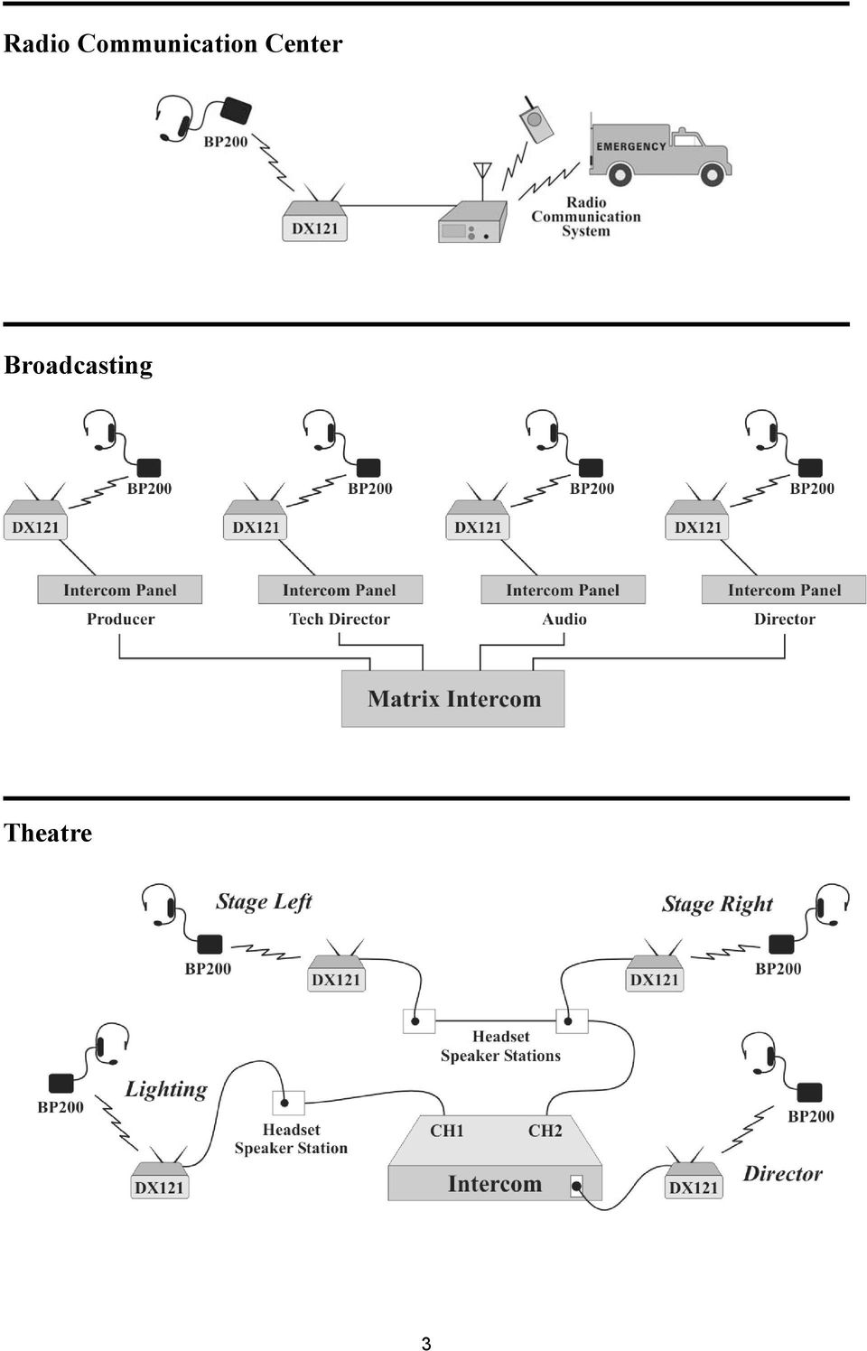
7 Radio Communication Center Broadcasting Theatre 3
8 EQUIPMENT IDENTIFICATION The DX121 One-to-One Wireless Intercom System includes a base station and may include any combination of COMMUNICATOR s. Other optional equipment may also be used with your system. As you unpack the equipment, check the enclosed shipping document to be sure you received all items listed. Base Station BS121 Base Station Base Station Antennas (2 per Base Station) 115/230 Volt AC Power Supply (1 per Base Station, with Power Cord) Communicators BP200 Beltpac HS15 Headset Beltpac Pouch Battery 2 per Beltpac or All-in-One Headset WH200 All-in-One Wireless Headset 115/230 VAC Power Supply with Power Cord for WS200 WS200 Wireless Speaker Station WS200 Battery Sled BP200 Beltpac HS15 Single-Muff Headset HS15D Dual-Muff Headset HS16 Lightweight Headset HS4-3 Earpiece & Lapel Microphone HSI6000 Headset Adapter OPTIONAL EQUIPMENT WH200 All-in-One Headset BAT41 Rechargeable Battery WS200 Wireless Speaker Station BAT850 Rechargeable Battery for WS200 AC850 Battery Charger for WS200 4

9 MAIN EQUIPMENT FEATURES Base Station Features Front Panel 1. POWER button 2. POWER light 3. BATT PWR (battery power) light 4. STATUS display 5. CLR/BND (clear/band) button 6. REG (registration) button 7. RESET button (recessed) 8. IC indicator light 9. ISO indicator light 10. HEADSET and 4W (4-Wire) IN and OUT audio level controls 11. Battery charger port 12. RDY (battery ready) light 13. CHG (battery charging) light Rear Panel 14. Antenna connector VDC power supply connector 16. Antenna connector 17. HEADSET / 4-WIRE connector block 18. PRI SEC (primary/secondary) switch 19. RELAY connector block 5
 light Rear Panel 14. Antenna connector 15. 12-14 VDC power supply connector 16. Antenna connector 17.")
10 Beltpac Features Headset cable connector 2. Beltpac power and transmit lights 3. ISO (Isolate) button 4. IC (Intercom) button 5. PWR (Power) button 6. Volume-up button 7. Volume-down button 8. Battery 9. Battery release latch All-in-One Headset Features Power light 2. Transmit light 3. IC1 & IC2 (Intercom) buttons 4. ISO (Isolate) button 5. Volume-up button 6. Volume-down button 7. Power button 8. Battery release latch 9. Battery 6
 buttons 4. ISO (Isolate) button 5. Volume-up button 6. Volume-down button 7. Power button 8.")
11 Speaker Station Features Left side panel Front panel Right side panel SIDE TONE adjustment (recessed) 2. Battery compartment cover 3. Battery compartment cover release latches 4. HEADSET connector 5. POWER button and light 6. CALL light and MIC (microphone) 7. SPEAKER button and light 8. ISO (Isolate) button and light 9. VOLUME down and up buttons 10. IC (Intercom) button and light VDC power adapter cable connector OHM SPKR external speaker connector 7
 button and light 9. VOLUME down and up buttons 10. IC (Intercom) button and light 11.")
12 SECTION 2. EQUIPMENT SETUP BASE STATION SETUP Basic Base Station Setup The following description is for a basic, stand-alone DX121 One-to-One Wireless Intercom System setup. Intercom headset, 4-Wire intercom and relay connections are described on page 22. Set up the Base Station as follows: Approximate 90 angle Antenna connectors VDC power connector Rear Panel Power light Power button Front Panel Step 1. Mount antennas - Mount the two enclosed antennas on the antenna connectors on the rear panel of the Base Station. Position the antennas at an approximate 90 angle. Turn the sleeve on each of the antenna connectors clockwise to tighten it securely in place. 8

13 Step 2. Connect power - Plug the connector at the end of the AC power supply cord into the 12-14VDC power connector on the rear panel of the Base Station, and turn the nut on the connector clockwise to secure it to the Base Station. Plug the female connector at one end of the power cord into the AC power supply, and plug the other end into an electrical outlet. Press the POWER button on the front of the Base Station to turn it on. The red light above the button should go on. Power supply connector Power cord connector To electrical outlet AC power supply Power cord Base Station rear panel Step 3. Charge batteries - IMPORTANT! Before using the DX121 system, charge the batteries for the Beltpacs and/or WH200 Headsets. Charging time for fully-discharged batteries is about 3 hours per battery. Green batteryready light Red batterycharging light Battery One battery can be charged in the battery charger at a time. Insert a battery in the charging port until it clicks in place. A red charging CHG light above the battery port stays on while a battery in the port is charging. A green ready RDY light above the battery port goes on when a battery in the port is fully charged. 9

14 Interference Avoidance Interference, which may be heard in a headset as popping sounds, may occur whenever other equipment such as WI-FI systems, wireless DMX systems, other HME Base Stations, etc. use the same frequency band. If these systems can be limited to one portion of the band, then the DX121 can be set to the opposite half of the 2.4 GHz to 2.48 GHz band. To avoid this type of interference, set up the base stations for split-band operation by selecting the upper part of the frequency range on one Base Station (or more), and the lower part of the frequency range on the other(s) as follows: Turn on the Base Station power. An 8 will appear on the STATUS display for a few seconds. After the 8 disappears and the STATUS display is blank, press and hold the CLR/BND button and then, while you are still holding the CLR/BND button, press and hold the REG button and wait until a L, H or A appears, and then release both buttons. Press the CLR/BND button to cycle through parts of the frequency band; L = Low end, H = High end and A = All. Stop on the band that you want to select. Wait until c appears on the display. NOTE: Base stations are shipped in the A (default) position. Multiple Base Station Setup This mode of operation can be used to expand the number of users communicating through multiple HME Base Stations operating in the same portion of the 2.4 GHz to 2.48 GHz frequency band. Primary and Secondary Base Station Settings One Base Station must be designated as Primary while the others are designated as Secondary. You can have only one primary and up to 3 secondary Base Stations. Secondary Base Stations are assigned numbers 1, 2, or 3. Label the Base Stations as Primary, 1, 2 and 3. Start with every Base Station and COMMUNICATOR power off. Locate the PRI SEC switch on the rear panel of the Base Station. Set the PRI SEC switch to the PRI position on the primary Base Station. Set the PRI SEC switch to the SEC position on each secondary Base Station. If a Base Station has been set for interference avoidance, it should be used as the primary Base Station. The secondary Base Stations will automatically be set to the same band when they are initialized. PRI SEC switch Rear panel of Base Station 10
 as follows: Turn on the Base Station power. An 8 will appear on the STATUS display for a few seconds.")
15 Base Station Initialization For multiple HME Base Stations to operate without interference, they must be properly initialized before performing any other setups. After initializing each Base Station, register each COMMUNICATOR that will be used with that base according to the procedures on pages NOTE: Base stations must be set up for split-band operation prior to initialization. (See Interference Avoidance on page 10.) Turn the primary Base Station power on. Register any Communicators to be used with the primary Base Station (See pages 13 20). Turn each Communicator off after registering it. Power on one secondary Base Station. The STATUS display will show a double bar, indicating the secondary base is ready to be initialized. Double bar Small o Base Station ready to be initialized Small "o" indicates primary base is open for registration Press the REG button on the primary base. The STATUS display will show a small o. To assign a number to a secondary Base Station and initialize it, press the REG button on the secondary base. Pressing the button repeatedly causes it to cycle through the numbers 1, 2, and 3. When the desired number appears, stop pressing and wait. While the secondary base initializes using the displayed number, the STATUS display will continue showing the secondary number selected. When initialization of the secondary Base Station is finished, the display will show one bar, to indicate the secondary has initialized to the primary. Secondary base number One bar Secondary 2 searching for primary Secondary is initialized to primary Press the REG button on the primary. The STATUS display will go blank. Register Communicators to the secondary (See pages 13 20). After registration, turn off the secondary base and all Communicators. 11
. Turn each Communicator off after registering it. Power on one secondary Base Station.")
16 Repeat these steps for each remaining secondary base. Use a different number for each. Only the primary base and the secondary base you are working with should have power on during initialization. All other equipment should be off. After all secondary bases are initialized and COMMUNICATOR s are registered power up all bases. Press RESET on the primary base and let it recover. Turn on the primary Communicators and let them link. Press RESET on each secondary base one at a time and let it initialize to the primary, as indicated by a single bar. Turn on the Communicators associated with the secondary bases. Do one group at a time until they have all linked. Then do the next group. At this point all bases and Communicators should be powered up and linked, ready for use. Now proceed with normal system configuration, setting functions and levels as required. If it becomes necessary to replace a secondary base, use the procedure above to initialize the new secondary with the same number as the old secondary. After initialization you will have to register any Beltpacs/Headsets associated with the old secondary to the new secondary. If it becomes necessary to replace a primary base, follow the above procedure completely. Before initialization of the secondary bases, clear the previous secondary initialization as follows. For each secondary, press the CLR/BND button and the RESET button at the same time. Continue holding the CLR/BND button after you release the RESET button, until the clear code c (lower case) appears on the STATUS display. Any Communicators associated with the old primary will have to be registered to the new primary after secondary base initialization. All Communicators associated with secondary Base Stations also have to be registered again. If the primary base is shut down or if the primary base is powered off for more than 30 seconds, all secondary bases will drop their Communicator connections and begin searching for the primary. If the primary is not found in 30 seconds, the secondary will automatically revert to primary-mode operation and reconnect the Communicators. At this point the secondary STATUS displays will show three bars. If the primary is turned back on it will be necessary to press RESET on all secondary bases to allow them to find and initialize to the primary again. It is therefore important to have all bases connected to the same AC circuit to prevent this situation when the system is shut down after hours and powered up again the next day. Three bars Secondary base operating in primary mode when no primary base is found NOTE: You cannot register Communicators to a base that is set to primary mode, and then switch the base mode to secondary for initialization. Once in secondary mode, the base cannot recognize the Communicators registered during primary operation. For secondary bases, the Communicators must always be registered after secondary base initialization, with the primary base remaining active and the secondary base displaying one bar. 12

17 BELTPAC / ALL-IN-ONE HEADSET / SPEAKER STATION SETUP AND REGISTRATION The first time you operate the DX121 system, you must register each BP200 Beltpac, WH200 All-In-One Headset and/or WS200 Speaker Station COMMUNICATOR for use with a specific Base Station. The Base Station will then recognize all registered Communicators when their power is on, and will know the difference between them and other electronic equipment operating on the same frequencies. If a Communicator is added, replaced or repaired later, the new one must be registered and the old one remains in memory. A maximum of 4 Communicators can be registered to a single Base Station at one time. If the maximum number of 4 is exceeded, you must clear all current registrations and re-register all active Communicators. NOTE: The following two pages are for Beltpac setup and registration. All-In-One Headset setup and registration instructions are on pages 15 and 16. Instructions for Speaker Station setup and registration are on pages Set Up Beltpacs Before registering them, set up all Beltpacs as follows. Step 1. Insert a fully charged battery in the Step 1 Beltpac, with the metal contacts on the end of the battery inserted first. Press it in until it snaps. Step 2 Step 3 Step 2. Place the Beltpac in the pouch. Step 3. Plug the headset cable connector into the Beltpac. Register Beltpacs Beltpacs must be within 6 feet (1.83 meters) of the Base Station while you are registering them. Be certain the Base Station power is on, and each Beltpac you are going to register is turned off before you begin. Beltpacs that are already registered can be on or off. NOTE: If you are setting up multiple Base Stations, the following steps must be repeated for Beltpacs being registered to each Base Station. Step 1. Put the headset, of the Beltpac being registered, on your head. Step 2. Press the REG button on the front panel of the Base Station (#6 on Base Station front panel illustration). The STATUS display (#4 on Base Station front panel illustration) will show a small o for open. NOTE: If you wait too long before going on to Step 3, the Base Station will go out of the registration mode and you will have to repeat Step 2. Step 3. Press and hold the ISO button on the Beltpac while you press and release the PWR (power) button to turn the unit on, then release the ISO button. This will cause the Beltpac to enter the registration mode. The two power lights at the corners of the Beltpac near the IC and ISO buttons will begin blinking red, then will blink green two or three times and go off. Wait! There may be a short delay. o

18 If registration is successfully completed: A voice message in the headset will say Power on, Beltpac #, Version #, Begin registration, Registration complete, After a delay of up to 15 seconds, the STATUS display will show the ID number assigned to this Beltpac for about 10 seconds. NOTE: ID numbers are assigned sequentially as 0 thru 3. The power light on the Beltpac, next to the IC button, will remain on steady green. Repeat Steps 1 to 3 at the bottom of page 13 for each Beltpac to be registered. If registration failed: A voice message in the headset will say Power on, Beltpac #, Version #, Begin registration, Both power lights on the Beltpac will be blinking red, and there may be a delay of up to 90 seconds before you hear Registration failed and the STATUS display (#4) goes blank. Press RESET (#7) on the Base Station. To press RESET, insert a small paper clip or similar object into the RESET hole at the lower-left corner of the Base Station front panel. When the STATUS display (#4) becomes blank, press the REG button (#6) and register the Beltpac again. If registration fails again, call your dealer for assistance. 4 6 F 7 5 If you try to register more than 4 COMMUNICATOR s to a Base Station: An F (for registration Full ) will appear on the STATUS display (#4) on the Base Station and you will hear Registration failed in the Headset. Clear all current registrations by pressing the CLR/BND button (#5) and RESET (#7) at the same time. To press RESET, insert a small paper clip or similar object into the RESET hole at the lower-left corner of the Base Station front panel. Continue holding the CLR/BND button after you release RESET, until the clear code c (lower case) appears on the STATUS display. c Register all active Beltpacs, one at a time. 14

19 Set Up All-In-One Headsets Before registering them, insert a fully charged battery in each Headset, with the metal contacts on the end of the battery inserted first. Press it in until it snaps. Power On/Off To turn power on Press and release the power button on the inside of the Headset housing. A voice message in the earpiece will say Headset # and the power light on the opposite side of the earpiece will go on. To turn power off Press and hold the power button for approximately 3 seconds. A voice message in the earpiece will say Headset off, and the power light on the opposite side of the earpiece will go off. Power button Power light Register All-In-One Headsets Headsets must be within 6 feet (1.83 meters) of the Base Station while you are registering them. Be certain the Base Station power is on, and each Headset you are going to register is turned off before you begin. Headsets that are already registered can be on or off. NOTE: If you are setting up multiple Base Stations, the following steps must be repeated for Headsets being registered to each Base Station. Step 1. Put the Headset on your head. 4 6 Step 2. Press the REG button on the front panel of the Base Station (#6 on Base Station front panel illustration). The STATUS display (#4 on Base Station front panel illustration) will show a small o for open. NOTE: If you wait too long before going on to o Step 3, the Base Station will go out of the registration mode and you will have to repeat Step 2. Step 3. Press and hold the ISO button on the Headset while you press and release the power button to turn the unit on, then release the ISO button. This will cause the Headset to enter the registration mode. The Headset power light will begin blinking red, then will blink green two or three times and go off. Wait! There may be a short delay. 15

20 If the registration is successfully completed: A voice message in the Headset will say Power on, Headset #, Version #, Begin registration, Registration complete, After a delay of up to 15 seconds, the STATUS display will show the ID number assigned to this Headset for about 10 seconds. NOTE: ID numbers are assigned sequentially as 0 thru 3. The power light on the Headset will remain on steady green. Repeat Steps 1 to 3 at the bottom of page 15 for each Headset to be registered. If registration failed: A voice message in the Headset will say Power on, Headset #, Version #, Begin registration, The power light on the Headset will be blinking red, and there may be a delay of up to 90 seconds before you hear Registration failed and the STATUS display (#4) goes blank. Press RESET (#7) on the Base Station. To press RESET, insert a small paper clip or similar object into the RESET hole at the lower-left corner of the Base Station front panel. When the STATUS display (#4) becomes blank, press the REG button (#6) and register the Headset again. If registration fails again, call your dealer for assistance. 4 6 F 7 5 If you try to register more than 4 COMMUNICATOR s to a Base Station: An F (for registration Full ) will appear on the STATUS display (#4) on the Base Station and you will hear Registration failed in the Headset. Clear all current registrations by pressing the CLR/BND button (#5) and RESET (#7) at the same time. To press RESET, insert a small paper clip or similar object into the RESET hole at the lower-left corner of the Base Station front panel. Continue holding the CLR/BND button after you release RESET, until the clear code c (lower case) appears on the STATUS display. c Register all active WH200 Headsets, one at a time. 16

21 Set Up Speaker Stations The Speaker Station can be used together with Beltpacs and All-in-one Headsets. It provides wireless communication through its built-in microphone and speaker, or a plug-in headset. A remote speaker can also be connected to the unit. The Speaker Station can be used on a table top or mounted on the wall. It can be operated with standard AC power, 12-14VDC or with six AA batteries or an optional rechargeable battery. A power supply with cord and a battery sled are provided. Whether used on a table top or mounted on the wall, if AC operation is required, the Speaker Station must be located close enough to an electrical outlet to be reached with the power supply and cord. Wall Mounting Hold the unit against the wall where you will mount it and mark the wall through the four holes in the flanges on its left and right sides. Drill holes in the wall at the four marked spots, and mount the WS200 over the holes with your selected hardware (not provided) AC Power Operation If using the WS200 with AC power Plug the connector at the end of the power supply cable into the VDC power connector on right side of the unit. Turn the sleeve on the connector clockwise to secure it to the unit. Plug the large female connector at one end of the AC power cord into the power supply. Plug the other end of the AC power cord into an electrical outlet. Power supply Power supply cable AC power cord Having a fully charged (or new) battery in its battery compartment when operating the WS200 with AC or external DC power can prevent interruption of communication during a power outage. The WS200 will automatically switch to battery power. 17
22 Battery Operation If using the Speaker Station with battery power Battery cover release latches Press down and pull out on the two battery cover release latches and lift the cover to open the battery compartment. Insert six AA batteries into the battery sled, in the positions shown inside the sled, and install the sled in the battery compartment. Battery sled with batteries Battery compartment Battery sled NOTE: An HME BAT850 Rechargeable NiMH Battery can be used instead. Close the battery compartment by pressing down on its cover next to both of the latches at the same time until they snap in place. 18
23 Register Speaker Stations The first time you operate a Speaker Station, you must register it for use with a specific Base Station. The Base Station will then recognize the Speaker Station when its power is on, and will be able to tell the difference between it and other electronic equipment operating on similar frequencies, or DX family Beltpacs or All-in-one Headsets. NOTE: The Speaker Station must be within 6 feet (1.83 meters) of the Base Station while being registered. Registration Procedure: Be sure the Speaker Station is turned off and the Base Station power is on. On the Base Station, press and release the REG button (#6). The STATUS display (#4) will show a small o for open. 4 6 o On the Speaker Station, press and hold the ISO button while you press and release the POWER button to turn the unit on, and then release the ISO button. This will cause the Speaker Station to enter the registration mode. The STATUS display on the Base Station will continue to show a small o. The ISO and IC lights on the Speaker Station will be blinking red then will change to a steady green IC light. ISO button and light IC button and light If registration is successfully completed: If you have a headset plugged into the Speaker Station or if the speaker is on, you will hear a voice message in the headset or speaker saying Power on, Speaker #, Version #, Begin registration, Registration complete After a delay of up to 15 seconds, the STATUS display on the Base Station will show the ID number assigned to the Speaker Station, for about 10 seconds. NOTE: ID numbers are assigned sequentially to registered COMMUNICATOR s as 0 thru 3. The IC light on the Speaker Station will remain on steady green. 19
24 If registration failed: A voice message will say Power on, Speaker, Version #, Begin registration, The ISO and IC lights on the Speaker Statio n will be blinking red, and there may be a delay of up to 90 seconds before you hear Registration failed, and the STATUS display (#4) goes blank. Press RESET (#7) on the Base Station. To press RESET, insert a small paper clip or similar object into the RESET hole at the lower-left corner of the Base Station front panel. When the STATUS display (#4) becomes blank, press the REG button (#6) on the Base Station and register the Speaker Station again. If registration fails again, call your dealer for assistance. 4 6 F 7 5 If you try to register more than 4 COMMUNICATOR s to a Base Station: An F (for registration Full ) will appear on the Base Station STATUS display (#4), and you will hear Registration failed. Clear all current registrations by pressing the CLR/BND button (#5) and RESET (#7) on the Base Station at the same time. To press RESET, insert a small paper clip or similar object into the RESET hole at the lower-left corner of the Base Station front panel. Continue holding the CLR/BND button after you release RESET, until the clear code c (lower case) appears on the STATUS display. c Register all active Speaker Stations, one at a time. 20
25 NOTICE You have completed the system setup. The instructions under INTERCOM AND RELAY CONNECTIONS on page 22 are for setting up auxiliary audio equipment which you may want to use with your DX
26 INTERCOM AND RELAY CONNECTIONS If using your DX121 with a wired intercom system, connect the intercom to the HEADSET/4-WIRE connector on the rear panel of the Base Station as shown below. Also, the RELAY connector shown below can be used as a dry contact for any outside equipment. Base Station rear panel showing HEADSET/4-WIRE and RELAY connectors Base Station front panel showing HEADSET and 4W (4-Wire) input and output level adjustments HEADSET/4-WIRE Connector Pin 1 SPKR Input Pin 2 Headset SPKR + Input Pin 3 connections MIC Output Pin 4 MIC + Output Pin 5 N/C Pin 6 GND Pin 7 4-WIRE Output Pin 8 4-Wire 4-WIRE + Output Pin 9 connections 4-WIRE Input Pin 10 4-WIRE + Input NOTE: Indicated PinOut connections should be matched to the corresponding PinOut connections of the intercom which will be used. RELAY Connector Pin 1 N.C. (Normally Closed) Pin 2 COM Pin 3 N.O. (Normally Open) Pin 4 IC SEL Pin 5 GND Intercom Headset Connection If using the headset connector of an intercom, connect the wires from a headset connector (not provided) to pins 1 through 4 of the HEADSET/4-WIRE connector on the rear panel of the Base Station. Be sure the headset jack of the intercom system is turned on. For intercom headset wiring diagram, see page Wire Intercom Connection If using a 4-Wire intercom, connect the wires from a 4-Wire connector into the HEADSET/4-WIRE connector on the rear panel of the Base Station. For 4-Wire wiring diagram, see page 34. Relay Operation In the default mode, the relay will operate only when the ISO button is pressed. In the IC SEL mode, the relay will operate only when the IC button is pressed. With either mode, the IC button activates audio to the HEADSET/4-Wire IN/OUT connector. The IC SEL mode is selected by placing a jumper across pins 4 and 5 of the RELAY connector. 22
27 SECTION 3. EQUIPMENT OPERATION BASE STATION OPERATION Front Panel Controls, Indicators and Connector 1. Power button Press the POWER button to turn the power on. A red light above the button will be lit when the Base Station power is on. Press the button again to turn the power off. The light will go off. All settings are preserved when the power is turned off, and will be restored when the power is turned on again. 2. Registration Controls and Status Indicator Use these controls to register each Beltpac, All-In-One Headset and/or Speaker Station COMMUNICATOR used with a specific Base Station. STATUS display shows the status of Communicators as they are being registered to the Base Station. REG button is used to set the Base Station in registration mode, so registration can begin. CLR/BND button and RESET switch when used together, clear all Communicator registrations from the Base Station. 3. IC (Intercom) and ISO (Isolate) Receiver Indicators and Controls Green lights indicate whether IC or ISO is being received. 4. Adjustments Use a screwdriver to adjust the HEADSET and 4W IN (input) and OUT (output) levels. 5. Indicators POWER When the DC power is on, the red POWER light will be lit. BATT PWR If the main DC power is disconnected while a battery is in the charging port, the Base Station will operate for a short time on the battery s power. When operating on battery power, both the green BATT PWR light and the red POWER light will be lit. CHG When the battery is charging, the red CHG light will be lit. RDY When the battery is fully charged, the green RDY light will be lit. 23
28 BELTPAC OPERATION The Beltpac control buttons have a snap action. They will activate when pressed firmly. Use your fingertips, not your fingernails, to press the buttons. Power On/Off Power On Press and release the PWR (power) button. A voice message in the earpiece will say Power on, Beltpac #, Version #, and the red power lights at the corners of the IC and ISO buttons will go on. After a short time, one light will go off and the other will change to green, indicating the Beltpac is ready for use. The STATUS indicator on the Base Station will momentarily indicate the ID of the Beltpac. Power Off Press and hold the PWR button for approximately 2 seconds. A voice message in the earpiece will say Power off, and the green power light will go off. NOTE: ISO and IC Power lights While the Beltpac is transmitting, the green power light will be flashing. The green power light will be on steady whenever the Beltpac is ready, but not transmitting. Either the ISO or IC button can be used to talk to other COMMUNICATOR s. IC will send the audio signal out to intercoms through the HEADSET and 4-WIRE connections on the rear panel of the Base Station. Depending on your Base Station RELAY operation setup (See page 22), either the ISO button or the IC button will activate any outside equipment connected to the RELAY connector on the rear panel of the Base Station. Push-To-Talk Mode To set the Beltpac for push-to-talk (PTT) communication, with the power off, press and hold the volume-down and ISO buttons while you press and release the PWR (power) button. You will hear Power on, Beltpac #, Version #, Hands-free off in the headset earpiece. Press and hold the IC or ISO button while talking. Hands-free Mode To set the Beltpac for hands-free communication, with the power off, press and hold the volume-up and ISO buttons while you press and release the PWR (power) button. You will hear Power on, Beltpac #, Version #, Hands-free on in your headset earpiece. When set up for hands-free communication, the Beltpac can be operated in either hands-free or PTT. ISO Lockout Mode To set the Beltpac with the ISO feature locked out, with the power off, press and hold the IC button while you press and release the PWR (power) button. You will hear Power on, Beltpac #, Version #, ISO off in your headset earpiece. When set up for the ISO Lockout mode, the ISO button will operate the same as the IC button, in either hands-free or PTT communication. To reset the ISO feature for normal ISO button communication, with the power off, press and hold the ISO and IC buttons while you press and release the PWR (power) button. You will hear Power on, Beltpac #, Version #, ISO on in your headset earpiece. NOTE: The above settings are saved in memory and only need to be repeated when you want to change between hands-free and PTT operation. When changing modes, if both power lights begin blinking, turn the Beltpac off and begin again. Hands-free and Push-To-Talk mode settings affect both IC and ISO. Individual adjustment is not possible. Push-To-Talk Mode Operation Press and hold the IC or ISO button while speaking. In PTT operation, audio will be transmitted only while you are pressing the IC or ISO button. Hands-free Mode Operation Quickly press and release the IC or ISO button to latch the transmitter on in the hands-free mode. Talk and listen, as in a normal telephone conversation. Press and release the IC or ISO button again to unlatch, to end the conversation. If either button is held down for more than a half second, the Beltpac will function as PTT. NOTE: In hands-free mode, pressing the IC button while latched in ISO will latch on IC. Pressing the ISO button while latched in IC will latch on ISO. 24
29 Volume Up/Down Volume Up Adjustment Each time you press and release the volume-up button, you will hear a higher pitch beep in the earpiece as the volume increases one step. If you press and hold the volume-up button, you will hear beeps of ascending pitch as the volume steps up to maximum. When maximum volume is reached, you will hear maximum repeating until you release the volume-up button. Volume Down Adjustment Each time you press and release the volume-down button, you will hear a lower pitch beep in the earpiece as the volume decreases one step. If you press and hold the volumedown button, you will hear beeps of descending pitch as the volume steps down to minimum. When minimum volume is reached, you will hear rapidly repeating beeps until you release the volume-down button. Sidetone Adjustment To adjust sidetone, the volume level of your own voice that you hear in the headset earpiece as you speak into the microphone, press and hold the IC button while you press the volume-up or volume-down button. If you reach the maximum volume level you will hear Maximum in the headset earpiece. If you reach the minimum volume level you will hear double beeps. Your sidetone setting will be saved in memory, and does not require readjustment each time the Beltpac is turned off and on. NOTE: This adjustment only affects the level of your voice in your own headset, not how anyone else hears you. Microphone Gain Adjustment Some users talk louder or softer than others. To allow for this, microphone gain adjustment is provided. To increase microphone gain Press the volume-up button while holding down the ISO button in the normal operating mode. The microphone gain increase can be monitored through sidetone, or preferably by someone else on a COMMUNICATOR or at the Base Station. To decrease microphone gain Press the volume-down button while holding down the ISO button in the normal operating mode. The microphone gain decrease can be monitored through sidetone, or preferably by someone else on a Communicator or at the Base Station. NOTE: You will hear Maximum if you attempt to go higher than maximum microphone gain. You will hear beeps if you attempt to go lower than minimum microphone gain. Microphone gain will be saved in non-volatile memory and does not require readjustment each time the power is turned on. Change Batteries When a battery becomes weak, a voice in the earpiece will say Change battery. When this happens, take the Beltpac out of its pouch and remove its battery. Slide the arrow-shaped battery-release latch in the direction of the arrow. Pull up on the end of the battery near the battery-release latch and lift the battery out of the Beltpac, or turn the Beltpac over and catch the battery in your hand. When replacing a battery in the Beltpac, place the end of the battery with the metal contacts into the battery holder on the Beltpac, in the same position as the battery you removed. Press the top of the battery carefully into the battery holder until it snaps in place under the battery-release latch. Recharge batteries according to the instructions on page 9. Battery Battery release latch 25
30 ALL-IN-ONE HEADSET OPERATION The Headset control buttons will activate when pressed lightly. Use your fingertips, not your fingernails, to press the buttons. Power On/Off Power On Press and release the power button on the inside of the Headset housing. A voice message in the earpiece will say Power on, Headset #, Version # and the power light will go on. The STATUS indicator on the Base Station will momentarily indicate the Headset ID number. Power Off Press and hold the power button for approximately 3 seconds. A voice message in the earpiece will say Power off, and the power light will go off. ISO and IC Power button Power light Transmit light The ISO, IC1 or IC2 buttons can be used to talk to other COMMUNICATOR s. IC will send the audio signal out to intercoms through the HEADSET and 4-WIRE connections on the rear panel of the Base Station. Depending on your Base Station RELAY connection setup (See page 22), either the ISO button or the IC button will activate any outside equipment connected to the RELAY connector on the rear panel of the Base Station. Push-To-Talk Mode To set the Headset for Push-To-Talk (PTT) communication, with the power off, press and hold the volume-down and ISO buttons while you press and release the power button. You will hear Power on, Headset #, Version #, Hands-Free off in the earpiece. Press and hold the IC1, IC2 or ISO button while talking. Hands-Free Mode To set the Headset for Hands-Free (HF) communication, with the power off, press and hold the volume-up and ISO buttons while you press and release the power button. You will hear Power on, Headset #, Version #, Hands-Free on in the earpiece. When set up for Hands-Free communication, the Headset can be operated in either HF or PTT. ISO Lockout Mode To set the Headset with the ISO feature locked out, with the power off, press and hold the IC1 button while you press and release the power button. You will hear Power on, Headset #, Version #, ISO off in your Headset earpiece. When set up for the ISO Lockout mode, the ISO button will operate the same as the IC1 button, in either hands-free or PTT communication. To reset the ISO feature for normal ISO button communication, with the power off, press and hold the ISO and IC1 buttons while you press and release the power button. You will hear Power on, Headset #, Version #, ISO on in your Headset earpiece. Lights-off Mode To prevent the power and transmit lights from coming on during headset operation, press and hold the IC2 button while you press the power button to turn the headset on. To return the lights to their normal functions, turn the power off and on again without pressing the IC2 button. NOTE: The above settings are saved in memory and only need to be repeated when you want to change between HF and PTT operation. When changing modes, if both power lights begin blinking, turn the Headset off and begin again. Hands-Free and Push-To-Talk mode settings affect both IC and ISO. Individual adjustment is not possible. Push-To-Talk Mode Operation Press and hold the IC1, IC2 or ISO button while speaking. In PTT operation, audio will be transmitted only while you are pressing the IC1, IC2 or ISO button. Hands-Free Mode Operation Quickly press and release the IC or ISO button to latch the transmitter on in the HF mode. Talk and listen, as in a normal telephone conversation. Press and release the IC or ISO button again to unlatch, to end the conversation. If either button is held down for more than a half second, the Headset will function as PTT. NOTE: In Hands-Free mode, pressing the IC1 or IC2 button while latched in ISO will latch on IC. Pressing the ISO button while latched in IC will latch on ISO. 26
31 Volume Up/Down Volume Up Adjustment Each time you press and release the volume-up button, you will hear a higher pitch beep in the earpiece as the volume increases one step. If you press and hold the volume-up button, you will hear beeps of ascending pitch as the volume steps up to maximum. When maximum volume is reached, you will hear maximum repeating until you release the volume-up button. Volume Down Adjustment Each time you press and release the volume-down button, you will hear a lower pitch beep in the earpiece as the volume decreases one step. If you press and hold the volumedown button, you will hear beeps of descending pitch as the volume steps down to minimum. When minimum volume is reached, you will hear rapidly repeating beeps until you release the volume-down button. Microphone Gain Adjustment Some users talk louder or softer than others. To allow for this, microphone gain adjustment is provided. To increase microphone gain Press the volume-up button while holding down the ISO button in the normal operating mode. The microphone gain increase can be monitored through sidetone, or preferably by someone else on a COMMUNICATOR or at the Base Station. To Decrease microphone gain Press the volume-down button while holding down the ISO button in the normal operating mode. The microphone gain decrease can be monitored through sidetone, or preferably by someone else on a Communicator or at the Base Station. NOTE: You will hear Maximum if you attempt to go higher than maximum microphone gain. You will hear two beeps if you attempt to go lower than minimum microphone gain. Microphone gain will be saved in non-volatile memory and does not require readjustment each time the power is turned on. Change Batteries When a battery becomes weak, a voice in the Headset will say Change battery. When this happens, remove the battery from the headset by carefully sliding the battery-release latch and lifting the battery out. When replacing a battery in the Headset, place the end of the battery with the metal contacts into the battery holder on the Headset, in the same position as the battery you removed. Press the top of the battery carefully into the battery holder until it snaps in place under the battery-release latch. Recharge batteries according to the instructions on page 9. Batteryrelease latch Battery 27
InnoMedia ESBC 9380-4B. Quick Install Guide. www.innomedia.com 1
 InnoMedia ESBC 9380-4B Quick Install Guide www.innomedia.com 1 Table of Contents Introduction 2 Package Contents 2 CAUTION 2 Installation 3 Wall-Mounting Instructions 5 Troubleshooting 6 Appendix A. LED
InnoMedia ESBC 9580-4B. Quick Install Guide. www.innomedia.com 1
 InnoMedia ESBC 9580-4B Quick Install Guide www.innomedia.com 1 Table of Contents Introduction 2 Package Contents 2 CAUTION 2 Installation 3 Wall-Mounting Instructions 5 Troubleshooting 6 Appendix A. LED
INSTALLATION GUIDE ConnectLine TV Adapter Getting started
 INSTALLATION GUIDE ConnectLine TV Adapter Getting started PURPOSE OF THIS GUIDE READ THIS FIRST Before your hearing instruments can receive sound from the TV, the adapter must be connected to the TV and
Innkeeper PBX. Desktop Digital Hybrid. User Guide. JK Audio
 Innkeeper PBX Desktop Digital Hybrid User Guide JK Audio Introduction Innkeeper PBX will allow you to send and receive audio through your multi-line PBX, ISDN or analog telephone. While this may seem like
Installation Instructions. Wireless Adapter/Repeater. Introduction. 30-3001-887 Rev C
 /Repeater Installation Instructions 30-3001-887 Rev C Workstation Ethernet bcx Controller Repeater Repeater Introduction Schneider Electric has designed a device that allows Andover Continuum controllers
USB Dual Handset Adapter for Nortel 1100-Series IP Phones
 1021 USB Dual Handset Adapter for Nortel 1100-Series IP Phones User Guide Document#: 90-00039 sales@algosolutions.com support@algosolutions.com www.algosolutions.com Table of Contents Algo 1021 USB Dual
RC8021 Indoor Camera Installation Guide
 RC8021 Indoor Camera Installation Guide P/N: 957YL502GJ Document Version: 1.0 Copyright 2011. All Rights Reserved. All trademarks and trade names are the properties of their respective owners i Package
PS 155 WIRELESS INTERCOM USER MANUAL
 PS 155 INTERFACE TO SIMPLEX WIRELESS INTERCOM USER MANUAL Issue 2011 ASL Intercom BV DESIGNED AND MANUFACTURED BY: ASL INTERCOM BV ZONNEBAAN 42 3542 EG UTRECHT THE NETHERLANDS PHONE: +31 (0)30 2411901
Energy Smart Electric Water Heater Controller
 Installation, Operation and Troubleshooting Instructions Energy Smart Electric Water Heater Controller Table of Contents Installation and Setup, 2 Operation, 5 Troubleshooting, 7 Regulatory Notices, 11
466-1936 Rev E October 2004 ZZZ*(6HFXULW\FRP. Part No: 60-883-95R. CareGard. User Guide
 ) *(6HFXULW\ 466-1936 Rev E October 2004 ZZZ*(6HFXULW\FRP Part No: 60-883-95R CareGard User Guide FCC Notices FCC Part 15 Information to the User Changes or modifications not expressly approved by GE Security
CS55H HOME EDITION... WIRELESS HEADSET SYSTEM
 CS55_HO_606.qxd /6/06 : PM Page ii WARRANTY Limited Warranty This warranty covers defects in materials and workmanship of products manufactured, sold or certified by Plantronics which were purchased and
Wireless Mouse USER GUIDE. for Mac. www.targus.com/us/formac ONE YEAR LIMITED WARRANTY N2953
 AMW43US / 410-1514-001C N2953 www.targus.com/us/formac 2008 Manufactured or imported by Targus Group International, Inc. (for U.S. sales: 1211 North Miller Street, Anaheim, CA 92806 USA, for Australia
PBXport. Rackmount PBX Digital Hybrid. User Guide. JK Audio
 PBXport Rackmount PBX Digital Hybrid User Guide JK Audio Introduction PBXport will allow you to send and receive audio through your multiline PBX, ISDN or analog telephone. While this may seem like a simple
ADA COMPLIANT BOX STYLE TELEPHONE INSTALLATION, PROGRAMMING AND OPERATING INSTRUCTIONS FOR MODEL PBX
 ADA COMPLIANT BOX STYLE TELEPHONE INSTALLATION, PROGRAMMING AND OPERATING INSTRUCTIONS FOR MODEL PBX INSTALLATION INSTRUCTIONS Step 1. Determine the position for the Hands-free phone in the elevator phone
Personal Assistance System Owner's Guide
 Owner's Guide PSC07 READ THIS FIRST This equipment generates and uses radio frequency energy, and if not installed and used properly, that is, in strict accordance with the manufacturers instructions,
Jabra BIZ 2400 USB USER MANUAL
 Jabra BIZ 2400 USB USER MANUAL 1 2011 GN Netcom A/S. All Rights Reserved. This user guide is published by GN Netcom A/S. The information in this user guide is furnished for informational use only, is subject
USER GUIDE. BLUETOOTH HEADSET system
 USER GUIDE Plantronics VOYAGER 510-USB BLUETOOTH HEADSET system 0 0 0 TABLE OF CONTENTS PACKAGE CONTENTS Package Contents 3 Features 4 Charging 5 Powering 6 Pairing 7 Installing PerSono Suite Software
ST815 Illumination Sensor with LCD
 ST815 Illumination Sensor with LCD The Illumination Sensor with LCD (refer to as Illumination Sensor hereafter) is a Z-Wave TM enabled device which is fully compatible with any Z-Wave TM enabled network.
C24-CAMANL Video Server/Encoder
 C24-CAMANL Video Server/Encoder User s Guide Table of Contents CHAPTER 1 INTRODUCTION... 1 Overview... 1 Physical Details - Video Server... 2 Package Contents... 3 CHAPTER 2 BASIC SETUP... 4 System Requirements...
SP1790JK 900MHz Wireless Indoor/Outdoor Speakers. User Manual INTRODUCTION FEATURES IMPORTANT SAFETY INFORMATION
 SP1790JK 900MHz Wireless Indoor/Outdoor Speakers INTRODUCTION This 900 MHz digital hybrid wireless speaker system uses the latest wireless technology that enables you to enjoy music and TV sound anywhere
User s Manual. Bluetooth Calculator Keypad. Page
 User s Manual Bluetooth Calculator Keypad Page Regulatory Compliance This device complies with Part 15 of the FCC Rules. Operation is subject to the following two conditions: (1) This device may not cause
Four-Line Intercom Speakerphone 944
 1 USER S MANUAL Part 2 Four-Line Intercom Speakerphone 944 Please also read Part 1 Important Product Information AT&T and the globe symbol are registered trademarks of AT&T Corp. licensed to Advanced American
WPR400 Wireless Portable Reader
 P516-098 WPR400 Wireless Portable Reader User guide Para el idioma español, navegue hacia www.schlage.com/support. Pour la portion française, veuillez consulter le site www.schlage.com/support. Contents
Plantronics.Audio 995 User Guide
 Plantronics.Audio 995 User Guide Welcome Congratulations on purchasing your new Plantronics.Audio 995. This User Guide contains instructions for setting up and using the.audio 995. Please refer to the
2.4 GHz Dual Handset Cordless Telephone Answering System 2255 with Caller ID/Call Waiting
 USER S MANUAL Part 2 2.4 GHz Dual Handset Cordless Telephone Answering System 2255 with Caller ID/Call Waiting Please also read Part 1 Important Product Information AT&T and the globe symbol are registered
Model 70A00-1. GSM Cellular Communications Center
 Home Automation, Inc. Model 70A00-1 GSM Cellular Communications Center Operation Manual Document Number 70I00-1 Rev A August, 2009 Contents Description... 1 Use with security systems...1 Everyday use...2
Thank you for choosing Zylight.
 Remote USER GUIDE Thank you for choosing Zylight. We at Zylight are happy that you chose the Remote. There are many lighting systems out there to choose from, and we think you will agree that what you
Wireless Home Security System Product Manual (Model #80355)
") Wireless Home Security System Product Manual (Model #80355) Installation Instructions During set-up, if no key is pressed for 15 seconds it will come out of the setup mode and you will have to start over.
Wireless Home Security System Product Manual (Model #80355) Installation Instructions During set-up, if no key is pressed for 15 seconds it will come out of the setup mode and you will have to start over.
Plantronics Inc 345 Encinal Street Santa Cruz, CA 95060 USA Tel: (800) 544-4660. www.plantronics.com
 544-4660. www.plantronics.com") Plantronics Inc 345 Encinal Street Santa Cruz, CA 95060 USA Tel: (800) 544-4660 www.plantronics.com 2005 Plantronics, Inc. All rights reserved. Plantronics, the logo design, Plantronics and the logo design
Plantronics Inc 345 Encinal Street Santa Cruz, CA 95060 USA Tel: (800) 544-4660 www.plantronics.com 2005 Plantronics, Inc. All rights reserved. Plantronics, the logo design, Plantronics and the logo design
User Guide Microsoft Screen Sharing for Lumia Phones (HD-10)
") User Guide Microsoft Screen Sharing for Lumia Phones (HD-10) Issue 1.1 EN User Guide Microsoft Screen Sharing for Lumia Phones (HD-10) Contents Safety 3 About your accessory 4 Keys and parts 5 Connect
User Guide Microsoft Screen Sharing for Lumia Phones (HD-10) Issue 1.1 EN User Guide Microsoft Screen Sharing for Lumia Phones (HD-10) Contents Safety 3 About your accessory 4 Keys and parts 5 Connect
Installation & Operation Manual HANDS-FREE BLUETOOTH MEDIA INTEGRATION KIT. Perfect for ANDROID TM
 GET CONNECTED Installation & Operation Manual HANDS-FREE BLUETOOTH MEDIA INTEGRATION KIT TranzIt BLU HF ISFM2351 Perfect for ANDROID TM Note to Readers, The information contained within the following documentation
GSM-EXT Cable Assembly Installation Guide
 GSM-EXT Cable Assembly Installation Guide For Documentation and Online Support: http://www.security.honeywell.com/hsc/resources/mywebtech General Information The GSM-EXT cable assembly is used to connect
WIRELESS STATUS MONITOR
 INSTALLATION INSTRUCTIONS WIRELESS STATUS MONITOR (WSM or AUWSM) The most current version of this document is available for download at: http://www.ir-swa.com P/N: M053-032-D Schlage 245 W. Roosevelt Road,
mysensors mysensors Wireless Sensors and Ethernet Gateway Quick Start Guide Information to Users Inside the Box mysensors Ethernet Gateway Quick Start
 mysensors Information to Users mysensors Wireless Sensors and Ethernet Gateway Quick Start Guide This equipment has been tested and found to comply with the limits for a Class B digital devices, pursuant
english ENGLISH Xbox 360 Wireless Headset
 ENGLISH Xbox 360 Wireless Headset thanks for choosing the Xbox 360 Wireless Headset. the headset s small size, wireless design, and noise-cancelling microphone allows you to conveniently chat with and
User Guide for the Wireless Headset (HS-11W) 9235346 Issue 1
 9235346 Issue 1") User Guide for the Wireless Headset (HS-11W) 9235346 Issue 1 DECLARATION OF CONFORMITY We, NOKIA CORPORATION declare under our sole responsibility that the product HS-11W is in conformity with the provisions
User Guide for the Wireless Headset (HS-11W) 9235346 Issue 1 DECLARATION OF CONFORMITY We, NOKIA CORPORATION declare under our sole responsibility that the product HS-11W is in conformity with the provisions
TELIKOU Intercom System. TM-200 Main Station. Instruction Manual
 Intercom System TM-200 Main Station Instruction Manual TELIKOU Systems All Rights Reserved I. Introduction Thank you for choosing TELIKOU intercom product. TM-200 main station is suitable for television
esata External Storage
 esata External Storage Operation Manual DA-ES110 Before reading this manual This operation manual contains basic instruction on installing and using esata External Storage, an IDIS product. Users who are
FB-500A User s Manual
 Megapixel Day & Night Fixed Box Network Camera FB-500A User s Manual Quality Service Group Product name: Network Camera (FB-500A Series) Release Date: 2011/7 Manual Revision: V1.0 Web site: Email: www.brickcom.com
2013 VTech Printed in China 91-009656-000 US
 Rechargeable Power Pack User s Manual 2013 VTech Printed in China 91-009656-000 US INTRODUCTION The Rechargeable Power Pack makes it easier than ever to keep the InnoTab 3 or InnoTab 3S charged and ready
SCREENLOGIC INTERFACE WIRELESS CONNECTION KIT
 SCREENLOGIC INTERFACE WIRELESS CONNECTION KIT FOR INTELLITOUCH AND EASYTOUCH CONTROL SYSTEMS INSTALLATION GUIDE IMPORTANT SAFETY INSTRUCTIONS READ AND FOLLOW ALL INSTRUCTIONS SAVE THESE INSTRUCTIONS Technical
WLAN600 Wireless IP Phone Administrator s Guide
 WLAN600 Wireless IP Phone Administrator s Guide Trademark Acknowledgement All brand names are trademarks or registered trademarks of their respective companies. Disclaimer This document is supplied by
OC810 Outdoor Camera Setup Guide
 OC810 Outdoor Camera Setup Guide P/N: 957YU60001 Document Version: 1.0 Copyright 2010. All Rights Reserved. All trademarks and trade names are the properties of their respective owner i Package Contents
Weather Radio Alarm Clock
 1200093 User s Guide Weather Radio Alarm Clock Thank you for purchasing your Weather Radio Alarm Clock from RadioShack. Please read this user s guide before installing, setting up, and using your new weather
IFS SP-PoE Splitter User Manual
 IFS SP-PoE Splitter User Manual P/N 1069176-EN REV 1.01 ISS 01JUL10 2011 UTC Fire & Security. All rights reserved. Content Overview 2 Package contents 2 Introduction 3 Product Specifications 3 Hardware
How To Use A U.S. Cell Phone At Home
 U.S. Cellular Home Phone 1 Contents Getting to Know Your Device...5 Appearance... 5 LED Indicators... 6 Device Installation...7 Before You Begin... 7 Installing the Battery... 7 Installing the Power Adapter...
56-A11A-10511. Plantronics Calisto Headset with Bluetooth USB Adapter. User Guide
 56-A11A-10511 Plantronics Calisto Headset with Bluetooth USB Adapter User Guide Table of Contents Package Contents... 1 Product Features... 2 Wearing Your Headset... 3 Powering... 4 Charging... 5 Indicator
56-K61A-15000. Plantronics Calisto Headset with Bluetooth USB Adapter. User Guide
 56-K61A-15000 Plantronics Calisto Headset with Bluetooth USB Adapter User Guide Table of Contents Package Contents... 1 Product Features... 2 Wearing Your Headset... 3 Powering... 4 Charging... 5 Indicator
ReadyNet Easy Jack 2 Voice/Data and Data Only Owner s Manual PX-211d and PX-211v
 ReadyNet Easy Jack 2 Voice/Data and Data Only Owner s Manual PX-211d and PX-211v Phonex Broadband Corporation dba ReadyNet 6952 High Tech Drive Midvale, Utah 84047 801.566.0100 Phone 801.566.0880 Fax www.readynetsolutions.com
Model: 616-146v2 Quick Setup Guide DC: 071015 Atomic Projection Alarm with Indoor and Outdoor Temperature
 Model: 616-146v2 Quick Setup Guide DC: 071015 Atomic Projection Alarm with Indoor and Outdoor Temperature Snooze/Backlight BUTTONS Time, Alarm with Snooze, & Calendar Projection Arm Rotates 180 Indoor/Outdoor
ITC-BTTN Cellular Bluetooth Gateway. Owner s Manual 1
 ITC-BTTN Cellular Bluetooth Gateway Owner s Manual 1 2 Table of Contents Introduction...3 Package Contents...3 XLink Connections Diagram...4 Setup...5 Pairing your Bluetooth Cell Phone to the XLink...6
User Guide. Soft-Touch TM Bluetooth Laser Mouse N2953
 Soft-Touch TM Bluetooth Laser Mouse 410-XXXXXXXXXXX 1 YEAR LIMITED WARRANTY: We pride ourselves on the quality of our products. For complete warranty details and a list of our worldwide offices, please
Safety Warnings and Guidelines
 Safety Warnings and Guidelines Thank you for purchasing this Wireless Speaker Amplifier! For best results, please thoroughly read this manual and carefully follow the instructions. Please pay extra attention
User Guide Lumia 950. Issue 1.0 EN
 User Guide Lumia 950 Issue 1.0 EN Keys and parts 1 Main camera 2 Loudspeaker 3 Audio connector 4 Front camera 5 Earpiece 6 Volume keys 7 Power/Lock key 8 Camera key 9 Charger connector 10 Microphone 2015
User s manual. w w w. v t e c h p h o n e s. c o m. Models: mi6885/mi6889/mi6890
 User s manual w w w. v t e c h p h o n e s. c o m Models: mi6885/mi6889/mi6890 Table of contents Getting started...................... 5 Parts checklist for mi6885............... 5 Parts checklist for
HANDS-FREE BLUETOOTH CONTROLLER for SMART READY TABLETS AND COMPUTERS
 HANDS-FREE BLUETOOTH CONTROLLER for SMART READY TABLETS AND COMPUTERS Operating Manual 2 CONTENTS Before Turning on Your PED... 4 Power... 5 ON... 5 OFF... 5 Modes... 6 Changing the MODE... 7 Connecting
THE NEW GENERATION IN TECHNOLOGY. NI-3103A Alarm Clock w/fm Radio ipod & iphone Docking. Operating Instructions
 THE NEW GENERATION IN TECHNOLOGY NI-3103A Alarm Clock w/fm Radio ipod & iphone Docking Operating Instructions Table of Contents Important Safeguards... 3 Parts... 6 Controls... 6 To Set Up... 7 ipod/iphone
Installer Guide smart connect
 Installer Guide smart connect TM 7330 Wireless Remote Humidity Sensor Please read all instructions before proceeding. The wireless remote humidity sensor monitors the humidity passing through the return
Dialog Telephone Interface Module Installation Sheet
 Dialog Telephone Interface Module Installation Sheet Description The Dialog Telephone Module (DTIM), model number 60-879- 95R, is a battery operated communication link between the security system control
BTS200 High-Definition Speaker. Haut-parleur haute définition BTS 200
 BTS200 High-Definition Speaker Haut-parleur haute définition BTS 200 Questions? Problems? Get help on the web at www.uniden.com or call our Customer Service line at 800-292-2294. Questions? Problèmes?
OC810 Outdoor Camera Installation Guide
 OC810 Outdoor Camera Installation Guide P/N: 957YU601GJ Document Version: 1.0 Copyright 2011. All Rights Reserved. All trademarks and trade names are the properties of their respective owner i Package
GETTING TO KNOW YOUR PRE-PAID TELSTRA WI-FI 4G
 GETTING TO KNOW YOUR PRE-PAID TELSTRA WI-FI 4G LET S GET THIS SHOW ON THE ROAD You must be excited about your brand new Pre-Paid Telstra Wi-Fi 4G. This guide will help you get connected as quickly and
BOSE. Link AL8 HOMEWIDE WIRELESS AUDIO LINK
 BOSE Link AL8 HOMEWIDE WIRELESS AUDIO LINK Français English SAFETY INFORMATION Please read this owner s guide Please take the time to follow the instructions in this owner s guide carefully. It will help
USER GUIDE CS50/55... WIRELESS OFFICE HEADSET SYSTEM
 USER GUIDE CS50/55... WIRELESS OFFICE HEADSET SYSTEM TABLE OF CONTENTS PACKAGE CONTENTS Package Contents Features Setup Setup - Handset Lifter (Optional) Charging Positioning Adjusting Fit Making/Answering/Ending
Business Audio System: Music & Messaging MP3 Player. by Grace Digital Audio. User Guide. Model No. GDI-USBM10
 Business Audio System: Music & Messaging MP3 Player by Grace Digital Audio User Guide Model No. GDI-USBM10 User Guide Contents Introduction 2 Safety & General Use Information 2 Features 3 Set Up & Operation
Hands-free phone system features (for cellular phone)
") Hands-free phone system features (for cellular phone) This system supports Bluetooth, which allows you to make or receive calls without using cables to connect a cellular phone and the system, and without
Hands-free phone system features (for cellular phone) This system supports Bluetooth, which allows you to make or receive calls without using cables to connect a cellular phone and the system, and without
User Manual. PePWave Surf / Surf AP Indoor Series: Surf 200, E200, AP 200, AP 400. PePWave Mesh Connector Indoor Series: MC 200, E200, 400
 User Manual PePWave Surf / Surf AP Indoor Series: Surf 200, E200, AP 200, AP 400 PePWave Mesh Connector Indoor Series: MC 200, E200, 400 PePWave Surf AP Series: Surf AP 200-X, E200-X, 400-X PePWave Surf
TABLE OF CONTENTS. TABLE OF CONTENTS... 1 Package content... 1. INTRODUCTION Dear customer... 2 Features... 2 Caution... 2
 Headset Englisch 19.07.2001 14:26 Uhr Seite 1 TABLE OF CONTENTS 1 TABLE OF CONTENTS............................................................... 1 Package content..................................................................
BSCAN DW VOX SAVE BEEP CHANNEL CALL VOX
 The World in Communication Content 2 ALAN 441 transceivers 2 1 user instructions 8 CHANNELS PMR446 TRANSCEIVER Congratulations on your purchase! ALAN 441 is a new generation PMR 446 transceiver which may
Wireless Alarm System. Alarm Siren. User s Manual. Choice ALERT. Control all Sensors & accessories from one location
 45136 Wireless Alarm System Alarm Siren User s Manual Low Batt On Armed ON/OFF LEARN Choice ALERT Control all Sensors & accessories from one location Table of Contents Important Safeguards 4 Introduction
Emergency Dialer DIAL-ALERT MODEL: AD-105. www.skylinkhome.com
 www.skylinkhome.com Emergency Dialer TM DIAL-ALERT MODEL: AD-105 If you would like to order Skylink s products or have difficulty getting them to work or download information and user manual, please :
ES-3305P V2 / ES-3308P V2. Quick Installation Guide. 09-2013 / v1.0
 ES-3305P V2 / ES-3308P V2 Quick Installation Guide 09-2013 / v1.0 1 COPYRIGHT Copyright Edimax Technology Co., Ltd. all rights reserved. No part of this publication may be reproduced, transmitted, transcribed,
HLWLAN 802.11b/g/n Transceiver Kit
 092524 RevB HLWLAN 802.11b/g/n Transceiver Kit Wireless Communications for OmniLogic Owner s Manual Contents Introduction...1 Installation...2 Configuration...6 Operation...8 Troubleshooting...9 HLWLAN
2100 POS System. 2100 User Guide
 2100 POS System 2100 User Guide Thank you for selecting UTC RETAIL s innovative Model 2100 Point of Sale solution! This guide is designed to acquaint you with the features and functionality of the 2100
Key. ➍ Micro USB Port ➎ Operating System Toggle Keys ➏ Foam Screen Protectors. ➊ On/Off switch ➋ Bluetooth Connect Button (flashes when searching)
") INSTRUCTION MANUAL ➏ ➋ ➊ Product Features ➎ ➍ ➌ Built-in wireless Bluetooth 3.0 keyboard Compatible across ios, Android, and Windows, enabling you to mix and match with devices Ultra-thin, lightweight
INSTRUCTION MANUAL ➏ ➋ ➊ Product Features ➎ ➍ ➌ Built-in wireless Bluetooth 3.0 keyboard Compatible across ios, Android, and Windows, enabling you to mix and match with devices Ultra-thin, lightweight
En g l i s h. Bluetooth Headset for Motorcycle. VOX Technology Intercom Technology Multi-Point Connection
 En g l i s h TOOTH Bluetooth Headset for Motorcycle VOX Technology Intercom Technology Multi-Point Connection Features Auto-Volume Level Adjusting Stereo (A2DP) Audio GPS A. PRODUCT DESCRIPTION: SHARKTOOTH
JABRA DRIVE USER MANUAL
 JABRA DRIVE USER MANUAL Contents THANK YOU...2 ABOUT YOUR JABRA DRIVE...2 WHAT YOUR JABRA DRIVE CAN DO....3 HOW TO PRESS THE BUTTONS...4 WHAT THE LIGHT MEANS...4 GETTING STARTED.............................................
Pad. Quick Start Guide
 Pad Quick Start Guide Copyright 2008 Mimio Congratulations on your mimio Pad purchase! mimio Pad is a 4 GHz wireless pad. To configure mimio Pad for use, install the mimio Studio software and plug the
Welcome to the GreatCall Family.
 pms2603 pms1235 pms226 pms298 How-To Guide Welcome to the GreatCall Family. Thank you for choosing the Jitterbug. At GreatCall, we ve made it easy for you to stay Orange - pms 143 connected to friends
CS540. Wireless Headset System. User Guide
 CS540 Wireless Headset System User Guide Contents Welcome 3 What s in the Box 4 Base and Headset Basics 5 Accessories 6 Customize Your Headset 7 Change Headset Configuration 7 Left Earloop Assembly 7 Headband
Alpha 10 SERVICE MANUAL. Downloaded from www.cbradio.nl. MAX 10 Meter Amateur Transceiver AM/FM/CW/SSB 6 BAND PROGRAMMABLE MODEL AM-1000.
 Alpha 10 MAX 10 Meter Amateur Transceiver MODEL AM-1000 AM/FM/CW/SSB 6 BAND PROGRAMMABLE SERVICE MANUAL Downloaded from www.cbradio.nl Cover Page LOUDER TALKBACK MOD Alpha 10 Max - Model AM-1000 4.7K Resistor
innkeeper PBX Desktop Digital Hybrid User Guide JK Audio Warranty
 Warranty Innkeeper PBX is covered by a 2-year warranty to be free from defective workmanship and materials. In the event that the innkeeper PBX needs repair, you must call us to get an authorization, and
Model: 308-1412 Manual DC: 080215 WIRELESS COLOR FORECAST STATION
 Model: 308-1412 Manual DC: 080215 WIRELESS COLOR FORECAST STATION FRONT VIEW SENSOR TX141TH-Bv2 LED TX Sensor Battery Cover Sensor Battery Compartment 2 AA Buttons Battery Compartment 3 AAA BACK VIEW Battery
DuraFon PRO Quick Reference Sheet
 DuraFon PRO Quick Reference Sheet RMA requests go to support section on www.engeniustech.com or email support@engeniustech.com EnGenius technical support is 888-735-7888 x 815 TIPS Customize the display
ATS-505. GB Version 1
 ATS-505 GB Version 1 Control Locations Power/Sleep Power On/off/Alarm off/sleep function Display Switch between radio frequency and time while radio is power on Mode Mode set up (please see below mode
25 Code GTO Digital Keypad
 2 Code GTO Digital Keypad Instructions for Wired and Wireless Installations (FM1-G only) Thank you for purchasing the GTO Digital Keypad. Be sure to read the directions carefully and completely. Before
CS70 WARRANTY MAINTENANCE TECHNICAL SUPPORT
 WARRANTY Limited Warranty This warranty covers defects in materials and workmanship of products manufactured, sold or certified by Plantronics which were purchased and used in the United States. This warranty
User Guide Nokia Bluetooth Headset BH-222
 User Guide Nokia Bluetooth Headset BH-222 Issue 1.0 EN-US BC User Guide Nokia Bluetooth Headset BH-222 Contents Safety 3 About your headset 4 Keys and parts 5 Charge your headset 6 Switch your headset
Technical Guide for Installation and Maintenance
 EV4500 ET4300 810-ECA 800-EFM Technical Guide for Installation and Maintenance Please read before using telephone. Getting Started Technical Guide for Installation and Maintenance What is the Epic System?
DSB-100 Portable Premium Bluetooth Speaker Owner s Manual
 . DSB-100 Portable Premium Bluetooth Speaker Owner s Manual You can print more than one page of a PDF onto a single sheet of paper. 1 Index Preparation Unpacking 3 Overview 4 Sound Quality 4 Design 4 Operation
Universal Host. Desktop Digital Hybrid. User Guide. JK Audio
 Universal Host Desktop Digital Hybrid User Guide JK Audio Introduction Universal Host will allow you to send and receive audio through your multi-line PBX, ISDN, VoIP or analog telephone. While this may
UK s best selling phone brand. User Guide. BT Big Button 200 Corded Phone
 UK s best selling phone brand User Guide BT Big Button 200 Corded Phone 2 Welcome. to your BT Big Button 200 telephone Large buttons for easy, accurate and more comfortable dialling Large display to assist
PS 29M DUAL CHANNEL BELTPACK IN METAL CASE
 PS 29M DUAL CHANNEL BELTPACK IN METAL CASE USER MANUAL October 2013 This product is designed and manufactured by: ASL Intercom BV Zonnebaan 42 3542 EG Utrecht The Netherlands Phone: +31 (0)30 2411901 Fax:
innkeeper PBX Desktop Digital Hybrid User Guide JK Audio
 innkeeper PBX Desktop Digital Hybrid User Guide JK Audio Introduction Innkeeper PBX will allow you to send and receive audio through your multi-line PBX, ISDN or analog telephone. While this may seem like
innkeeper PBX Desktop Digital Hybrid User Guide JK Audio Warranty
 Warranty Innkeeper PBX is covered by a 2-year warranty to be free from defective workmanship and materials. In the event that the innkeeper PBX needs repair, you must call us to get an authorization, and
H203D 中文 GB Version 1
 H203D 中 GB文 Version 1 Contents Installing batteries... 4 Using the AC adapter (not supplied)... 5 Setting the clock... 6-7 Updating your radio - DAB... 8 Selecting a station - DAB... 9 Secondary services
DP-236Q Wireless Video Door Phone
 DP-236Q Wireless Video Door Phone Manual 3 1 Wireless operation camera and monitor can operate from up to 492ft (150m) 2 away Remotely and securely talk to visitors and unlock doors or gates via the monitor
Alarm Clock USER GUIDE
 Alarm Clock USER GUIDE Jazwares, Inc. 2012 CONTENTS Please read the instructions along with the Alarm Clock carefully before you use it, so that you can operate it conveniently. WELCOME & Warnings Page
Nucleus CP810 Sound Processor and Nucleus CR110 Remote Assistant Troubleshooting Guide
 Nucleus CP810 Sound Processor and Nucleus CR110 Remote Assistant Troubleshooting Guide Symbols Contents Note Important information or advice. Can save inconvenience. Tip Time saving hint or saves inconvenience.
PAR Tablet 10 Quick Start Guide
 ParTech, Inc. 8383 Seneca Turnpike New Hartford, NY 13413 p.800.458.6898 www.partech.com PAR Tablet 10 Quick Start Guide PN 770505503 This material has been created in order to accommodate a wide range