ESCO #90538 For Sales, Service, and Parts Contact ESCO at
|
|
|
- Morris McCoy
- 8 years ago
- Views:
Transcription
1 ESCO #90538 For Sales, Service, and Parts Contact ESCO at Flight Path Drive, Brooksville FL,

2 A Instruction manual Compac wheel dolly, model WD1500. Important: Read and understand the instruction before use! Operating and service manual for wheel dolly model WD 1500 Max. Capacity 1500 kg. Instruction and responsibility: This instruction and safety manual must be enclosed with the wheel dolly at all times. It is very important that the owner and the operator completely understand the operating, safety and maintenance instructions before use. The manufacturer is not liable for wrong- or irresponsible use or maintenance due to the operators not knowing and following these instructions. If the operator is not fluent in English, then these instructions and warnings shall be read and explained to the operator in the operator's native language, making sure that he understands its contents. How to use the wheel dolly: WD1500 is a mobile wheel dolly for demounting and mounting large wheels with an outside diameter of 1150 mm up to 2150 mm (84 ). The wheel / load is lifted when the 2 x 4 rollers press horizontally on each side of the wheel. Lifting will require more force in the beginning as the rollers are pressing against each other. Lifting occurs with pumping the handle (P). Lowering the wheel/load is activated by moving the foot pedal (E) into the opposite position. The pump handle (P) can then be used for lowering the wheel/load again. Operating instruction: The unit is operated by moving the foot pedal (E) into lifting or lowering position and afterwards pumping the pump handle (P). Labelling: Warning and CE approval labels are fitted onto the unit. Make sure that lifting only occurs on a flat and strong surface / floor. The wheel/load must be lifted in a vertical angle as the wheel/load might otherwise slide on the rollers away from the unit causing the unit to move towards the operator. Mounting: After opening the packaging check the unit for visible damage, leakage, etc. Please recycle or use the packing material again.

3 A M W K H L P F F S E Safety instructions - LIFTING 1. Make sure that lifting only occurs on a flat and strong surface/floor. If not, lifting with this unit is prohibited due to risk of danger / damages! 2. The wheel/load should be lifted from the floor. 3. Place the rollers (F) on either side of the wheel that should be lifted. Move the unit as close to the wheel/load as possible. 4. Loosen the vertical support arm (H) and horizontal support arm (A). By using grip (K) it is possible to steer the arm with the small support wheel (W) to the opposite side of the wheel/load. Once the small support wheel (W) is on the opposite side it can be steered behind the wheel/load. This will prevent the wheel/load from dropping to the opposite side during manoeuvring. 5. Once you have placed the guide arm (A) correctly, lock its position with the lock (M). 6.!! Lock (L) should be open while lifting or lowering so that the wheel (W) supports the wheel/load on the opposite side. Kindly note that you should NOT lock position (L). Once you begin lifting the wheel/load, lock (L) must be open, as this will allow the guide arm to follow the upwards and downwards movement of the wheel as it is raised and lowered. 7. The lifting can now start. * * Before you end the lifting procedure, active safety pin (S) so that the manual safety stop is activated, should a hydraulic leak occur. After a short lifting or lowering action the safety pin (S) will be activated. The safety pin is spring loaded and will lock the movement of the lifting arms. To unlock the safety stop pump a little in the opposite direction so that the safety pin (S) can be pulled up again.
 it is possible to steer the arm with the small support wheel (W) to the opposite side of the wheel/load.")
4 Safety instruction - LOWERING / MOUNTING OF WHEEL 1. Release the safety pin (S). 2. Inspect that the small wheel (W) has a firm grip on the wheel/load before lowering. 3. Before lowering the wheel/load make sure that vertical guide lock (L) is released and free to move. 4. Once you slowly start lowering the wheel/load, the guide arm (L) should be able to freely follow the movement of the wheel. If not, the risk is that the wheel will drop away from its support (W) on the opposite side of the wheel and could thereby accidentally fall. 5. Activate the pump lever (P) to lower the load or reach the correct mounting height. 6. Once the unit can be removed from the wheel/load, release locks (K) and swing wheel (W) away from the wheel. Pull back the unit. Safety instruction MANOEUVRING WITH WHEEL/LOAD 1. Ensure that the small support wheel (W) is supporting the wheel/load correctly. 2. Ensure that the locks (M), (L) and (S) are in locked position. WARNING Safety instructions: Make sure that lifting only occurs on a flat and strong surface/floor. The wheel/load must be lifted in a vertical angle as the wheel/load might otherwise slide on the rollers away from the unit causing the unit to move towards the operator. Do not overload the unit! Overloading with loads over 1500 kg could result in damage to the unit or in worst case cause other damage and even accidents! Lowering a load of more than 1500 kg onto the unit may lead to serious damage to the unit. Example: If the operator lowers the vehicle itself before lowering and moving the wheel dolly away from the vehicle. Before lifting / transporting a load the operator MUST take precautions that the load is not allowed to drop, and that the weight distribution is safe. The operator must before use take precautions that all pins are safely locked with split pins or lock rings. (ATTENTION! The LOAD must be blocked with the guide arm (K) locked and (W) in correct position to support the wheels on the opposite side.) Always lower the load to the lowest possible position before transportation. Important! The safety valve is calibrated and sealed by the manufacturer and it is ABSOLUTELY PROHIBITED to open the seal or adjust its calibration. Offence against the above safety instructions could in worst case result in loss of the load which could cause personal injury and/or damage to the unit or properties. In case the unit has any irregularities which could affect the safety, the unit must not be operated until it has been repaired. The unit should not be used if there are any oil leakages or if the unit seems different to use than when it was new. In such cases the unit should be inspected/repaired by a skilled person. More information on spare parts, etc is available on under Services. The manufacture is not liable for wrong use, changes to the construction, use of other spare parts than original or adjustments/repairs by unauthorised persons. Safety Maintenance: Inspection of the unit must only be done without load, for safety reasons. Only authorized/skilled personnel may repair/adjust the unit. Use only original parts. For adjustment follow the instructions of the manufacturer. For further information please contact
 on the opposite side of the wheel and could thereby accidentally fall. 5.")
5 Maintenance: At normal use all mechanical/moving parts only requires a monthly lubrication to be maintained. The pins must be greased every three months. Important! Use only oil or grease free from acid. An annual inspection must be performed by a skilled person. Every eventually wearing out or defective part must be replaced with original spare parts. The owner and- or user must take precautions that repair is made by a skilled person. Before every use the operator must take precautions that there are no visible faults such as leaks, damage of the WD and loose or missing parts. In case the operator suspects that the unit has been overloaded or wrongly loaded it must before further use be inspected by a skilled person or an authorized. Oil: Volume: Type: DO NOT use brake fluid, motor oil, etc! 0.6 litres. Use only hydraulic oil with a gradation (viscosity) of AWS22. Compac recommends Castrol. In case the hydraulic unit has a lack of oil or has been taken apart in order to replace the seals then fill up with the correct oil quantity. Activate the pump handle and add oil slowly through the filling hole at the plug. The lifting arms must be in minimum position (as close together as possible) when refilling oil. Warning! Too much oil quantity might cause problems to the hydraulic system. Decommissioning: If the unit should ever be scrapped, draw off the oil into an approved container and dispose it at an approved authority GB/VL

6 3458A 3461A

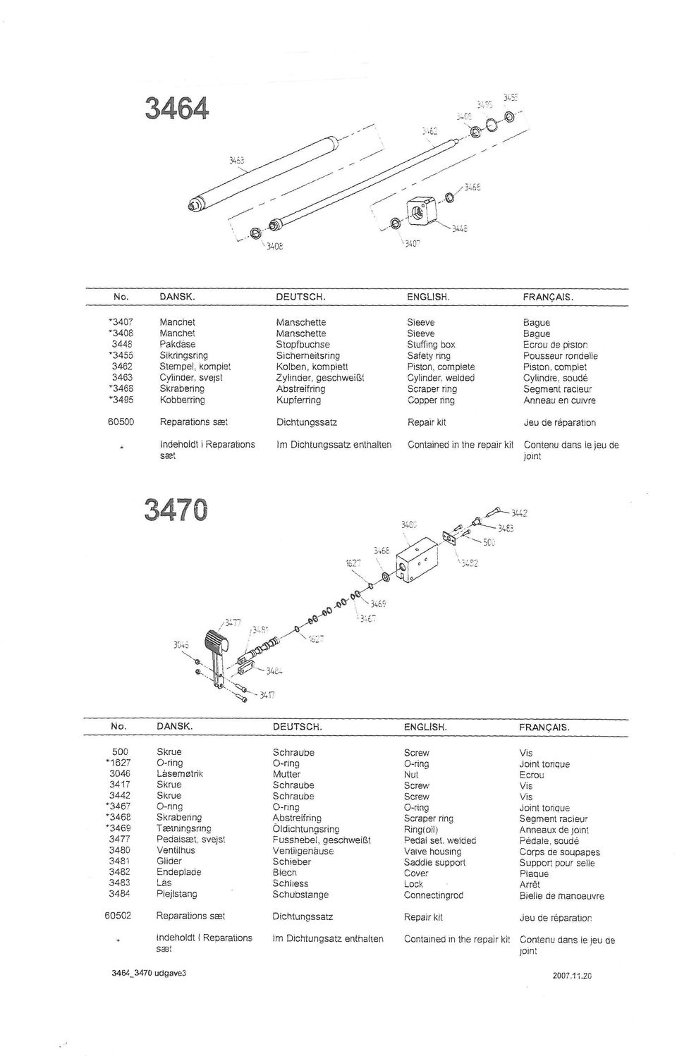
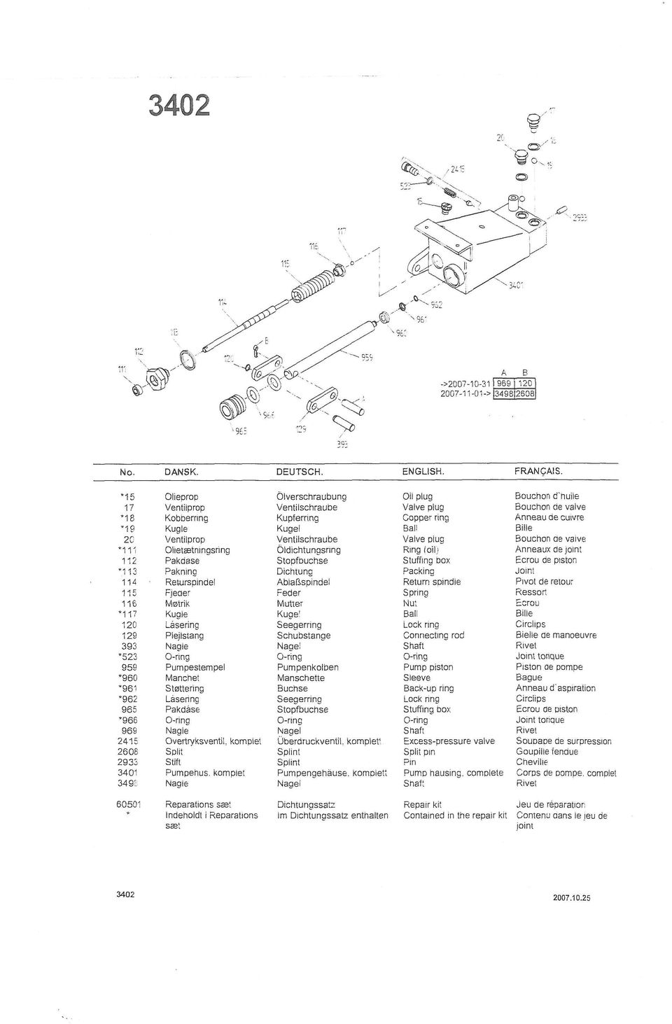
7 WD1500 G3 No. DANSK. DEUTSCH. ENGLISH. FRANÇAIS. 140 Skrue Schraube Screw Vis 206 Split Splint Split pin Goupille 828 Fitting Fitting Fitting Raccord 1144 Skrue Rietstockschraube Pointed screw Vis pointue 1208 Trykfjeder Feder Spring Ressort 1314 Skive Scheibe Washer Rondelle 1324 Spændstift Spannstift Elastic pin Goupille de serrage 1421 Skrue Schraube Screw Vis 1540 Fitting Fitting Fitting Raccord 1711 Oliebremse Senkbremse Oil valve Frein d`huile 2067BL Hjul Rad Wheel Roue 2185 Fitting Fitting Fitting Raccord 2641 Møtrik Mutter Nut Ecrou 2802 Møtrik Mutter Nut Ecrou 2934 Bolt Bolzen Bolt Boulon 3036 Fjedersplit Splint Split pin Goupille 3046 Låsemøtrik Mutter Nut Ecrou 3064 Skrue Schraube Screw Vis 3076BL Plastprop Kunststoffverschluß Cap Bouchon 3192 Skrue Schraube Screw Vis 3384 Låsering Seegerring Lock ring Circlips 3402 Pumpe, komplet Pumpe, komplett Pump, complete Pompe, complète 3440 Kugle/håndtag Kugel Ball Bille 3441 Håndtag Handgriff Handle Manche 3443 Skrue Schraube Screw Vis 3444 Skrue Schraube Screw Vis 3446 Rulle Rolle Roller Poulie 3453 Aksel Achse Shaft Axe 3454 Bøsning Buchse Bushing Manchon 3456 Stop f. cylinder Halt Stop Arrêt 3457 Trykrør Druckrohr Pressure pipe Tuyau de refoulment 3458A Tårn, teleskop Zwinger, teleskop Tower, telescope Chateau, télescope 3459 Støtterør, komplet Stürtz Rohr, komplett Supporting pipe, compl. Support de Tuyau, compl Rulleophæng, komplet Chassis, komplett Chassis, complete Châssis, complète 3461A Tårn Zwinger Tower Chateau 3464 Cylinder, komplet Zylinder, komplett Cylinder, complete Cylindre, complète 3470 Omskiftventil, komplet Ventil, komplett Valve, complete Soupape, complète 3471 Trykrør, komplet Druckrohr, komplett Pressure pipe, complete Tuyau de refoulment, co Trykrør Druckrohr Pressure pipe Tuyau de refoulment 3473 Pumpearm, komplet Pumpenarm, komplett Fulcrum arm, complete Levier de pompage, com Trykrør Druckrohr Pressure pipe Tuyau de refoulment 3475 Trykrør Druckrohr Pressure pipe Tuyau de refoulment 3485 Hus f. Lås Gehäuse Housing Corps 3486 Låsetap Zapfen Pin Cliquet de àrrêt 3487 Knop f. Lås Handgriff Handle Manche 3488 Skærm Blech Sheet Plaque 3489 Hus f. bremse Gehäuse Housing Corps 3492 Skrue Schraube Screw Vis 3496 Hjul m. bremse, komplet Rad mit bremsen, komplett Wheel w. breakes, compl. Frain pour roue, complète 3497 Hjul, komplet Rad, komplett Wheel, complete Roue, complète 0AL006 Skilt Abseichen Badge Insigne 0CC028 Nagle Bolzen Shaft Rivet

8
9
HYDRAULIC TABLE CART 500-LB.
 HYDRAULIC TABLE CART 500-LB. OWNER S MANUAL WARNING: Read carefully and understand all MACHINE ADJUSTMENT AND OPERATION INSTRUCTIONS before operating. Failure to follow the safety rules and other basic
Pallet Jack. OWNER S MANUAL Model MH1230. Important Safety Instructions Assembly Instructions Parts and Hardware Identification
 OWNER S MANUAL Model MH1230 Important Safety Instructions Assembly Instructions Parts and Hardware Identification Pallet Jack CAUTION: Read, understand and follow ALL instructions before using this product
HYDRAULIC LIFT TABLE CART 2200-LB.
 HYDRAULIC LIFT TABLE CART 2200-LB. OWNER S MANUAL WARNING: Read carefully and understand all MACHINE ADJUSTMENT AND OPERATION INSTRUCTIONS before operating. Failure to follow the safety rules and other
HYDRAULIC TABLE CART
 Owner s Manual & Safety Instructions Save This Manual Keep this manual for the safety warnings and precautions, assembly, operating, inspection, maintenance and cleaning procedures. Write the product s
Infomail 2/2010 BPW BERGISCHE ACHSEN. repair set for spring bolt storage (adjustable support, lateral axle lifting device, welded wear plates)
") BPW INFO-MAIL BPW BERGISCHE ACHSEN Vertrieb Aftermarket New Repair Sets New repair sets have been assembled to simplify spare part assignment: 09.801.07.75.0 (adjustable support, lateral axle lifting device,
BPW INFO-MAIL BPW BERGISCHE ACHSEN Vertrieb Aftermarket New Repair Sets New repair sets have been assembled to simplify spare part assignment: 09.801.07.75.0 (adjustable support, lateral axle lifting device,
Operating Instructions Parts List Manual Scissor Lift Pallet Truck
 Operating Instructions Parts List Manual Scissor Lift Pallet Truck Note: Operator MUST read and understand this operating instructions before use this Hand Scissor Lift. Thank you for using this hand scissors
1 TON FOLDING CRANE CFC1000
 1 TON FOLDING CRANE CFC1000 OPERATION &MAINTENANCE INSTRUCTIONS 0401 SPECIFICATIONS MAXIMUM SAFE WORKING LOADS (kg) 1 2 3 4 1000 750 500 250 MAXIMUM LIFT HEIGHT - 1920mm HYDRAULIC RAM OIL CAPACITY - 450CC
Service Manual Rol-Lift
 R 2000 Service Manual Rol-Lift Series: T and E Developed by Generic Parts Service This manual is intended for basic service and maintenance of the Rol-Lift pallet jack. The pallet jacks you are servicing
Instructions and precautions. Fork Height. Visit our website at: http://www.harborfreight.com
 Pallet Jack Item 68760 / 68761 Instructions and precautions Specifications Capacity Control Lever Fork Height Fork Length Fork Width Maximum Minimum Width over Forks Steering Wheel Dia. 2-1/2 Ton (5,000
MODEL 565E - 22 TON AIR/HYDRAULIC AXLE JACK
 1 565AKHU HYDRAULIC 1.22 O-RING - 2 REQUIRED UNIT 1.23 O-RING COMPLETE 1.24 TEFLON O-RING 2 REQUIRED 1.3 EXTENSION SCREW 1.3A SPRING PIN 1.4 SPRING SUPPORT 1.5 SCREW BUSHING 1.6 Y SHAPE SEAL RING 1.7 HEAD
PALLET JACK - 2.5 TON
 PALLET JACK - 2.5 TON 39939 SET UP AND OPERATING INSTRUCTIONS Visit our website at: http://www.harborfreight.com Read this material before using this product. Failure to do so can result in serious injury.
REPAIR INSTRUCTIONS UNDER BODY CYLINDER (UM, UL)
") Table of contents 1. Introduction... 3 1.1. Scope of use... 3 1.2. General remarks... 3 1.3. Contact Hyva... 3 1.4. Precautions... 4 1.5. Spare parts... 4 1.5.1. Prior to use... 4 1.6. Recycling and Reuse
Table of contents 1. Introduction... 3 1.1. Scope of use... 3 1.2. General remarks... 3 1.3. Contact Hyva... 3 1.4. Precautions... 4 1.5. Spare parts... 4 1.5.1. Prior to use... 4 1.6. Recycling and Reuse
DANGER DANGER. General Information. Safety Is Your Responsibility. Ordering Parts. Contact Information
 Safety Safety Is Your Responsibility DANGER To avoid personal injury or death, carefully read and understand all instructions pertaining to the Anthony Liftgates product. Do not attempt to install, operate,
Operating Instructions Hand pallet trucks HU Profi. Issue 08.2000
 Operating Instructions Hand pallet trucks HU Profi Issue 08.2000 Index 1 Introduction 1.1 Product description 1.2 General information on service and maintenance 1.3 Spare parts 1.4 Dimensions 2 Correct
LIFT N RACK PRO OPERATING & INSTALLATION GUIDE 5500 Lb. LIFT CAPACITY
 LIFT N RACK PRO OPERATING & INSTALLATION GUIDE 5500 Lb. LIFT CAPACITY IMPORTANT: READ THIS MANUAL BEFORE IN-STALLING, OPERATING OR MAINTAINING YOUR LIFT. Chassis Liner Company Sales Office Toll Free: 800-242-2448
Hydraulic Transmission Jacks Operating Instructions & Parts Manual
 Blackhawk Automotive is a Licensed Trade Mark Made by SFA Companies, Kansas City, MO Hydraulic Transmission Jacks Operating Instructions & Parts Manual Model BH7011 BH7210 Capacity 1/2 Ton 1 Ton SFA Companies
Failure to comply with the following cautions and warnings could cause equipment damage and personal injury.
 1.0 IMPORTANT RECEIVING INSTRUCTIONS Visually inspect all components for shipping damage. Shipping Damage is not covered by warranty. If shipping damage is found, notify carrier at once. The carrier is
INSTRUCTIONS AND PARTS LIST FOR MODEL 70H & 75H HAND-OPERATED HYDRAULIC PRESS
 INSTRUCTIONS AND PARTS LIST FOR MODEL 70H & 75H HAND-OPERATED HYDRAULIC PRESS SETTING UP THE PRESS FOR OPERATION For shipping convenience, the gauge, pump handle, hoist crank, screw nose and base angles
1000-LB. TRAILER JACK OWNER S MANUAL
 1000-LB. TRAILER JACK OWNER S MANUAL WARNING: Read carefully and understand all INSTRUCTIONS before operating. Failure to follow the safety rules and other basic safety precautions may result in serious
OPERATOR S INSTRUCTION MANUAL
 POWER JACK MATERIAL MOVER OPERATOR S INSTRUCTION MANUAL WARNING: Serious injury may result if this product is misused. The manufacturer provides the following instructions for use and care of this equipment
INSTRUCTIONS. FLHR/C/S (Road King) FRONT END LOWERING KIT 1WARNING -J03242 REV. 10-19-04. General. Removal (Left and Right Forks) Kit Number 54614-05
 FRONT END LOWERING KIT 1WARNING -J03242 REV. 10-19-04. General. Removal (Left and Right Forks) Kit Number 54614-05") INSTRUCTIONS -J04 REV. 0-9-04 General FLHR/C/S (Road King) FRONT END LOWERING KIT This kit is designed for installation on 00 and later FLHR/C/S Model Motorcycles. Road King models use the conventional
INSTRUCTIONS -J04 REV. 0-9-04 General FLHR/C/S (Road King) FRONT END LOWERING KIT This kit is designed for installation on 00 and later FLHR/C/S Model Motorcycles. Road King models use the conventional
FJ2. 2 Ton Trolley Floor Jack Assembly & Operating Instructions
 FJ2 2 Ton Trolley Floor Jack Assembly & Operating Instructions READ ALL INSTRUCTIONS AND WARNINGS BEFORE USING THIS PRODUCT. This manual provides important information on proper operation & maintenance.
10 TON HYDRAULIC PRESS
 10 TON HYDRAULIC PRESS Model Nos. CSA10F and CSA10B OPERATING & MAINTENANCE INSTRUCTIONS 0200 SPARE PARTS and SERVICING Please contact your nearest dealer, or CLARKE International, on one of the following
Table of Contents. Overview 1. Pump Disassembly 2. Control Disassembly / Reassembly 7. Pump Reassembly 13. Adjustment Procedures DR Control 19
 Table of Contents Overview 1 Pump Disassembly 2 Control Disassembly / Reassembly 7 Pump Reassembly 13 Adjustment Procedures DR Control 19 Adjustment Procedures DRG Control 20 Adjustment Procedures DFR
Failure to comply with the following cautions and warnings could cause equipment damage and personal injury.
 1.0 IMPORTANT RECEIVING INSTRUCTIONS Visually inspect all components for shipping damage. Shipping Damage is not covered by warranty. If shipping damage is found, notify carrier at once. The carrier is
CUTTER-CRUSHER RAMMER RC 22
 11/99 PARTS MANUAL PMRC22EN.A99 CUTTER-CRUSHER RAMMER RC 22 SERIAL NO. RC22BC0015-UP RC22RC0021-UP TABLE OF CONTENTS 1. Cylinder RC 22.......................................................... 4 2. Hydraulics
Mini Pallet Jack OWNER S MANUAL
 Mini Pallet Jack OWNER S MANUAL WARNING: Read carefully and understand all ASSEMBLY AND OPERATION INSTRUCTIONS before operating. Failure to follow the safety rules and other basic safety precautions may
EXCAVATOR SAFETY TRAINING
 EXCAVATOR SAFETY TRAINING INSPECTION CHECKLIST INSPECTION AREA INSPECTION RESULTS Sat. Unsat. N/A Comments Carrier & Car Body Rotation system Tracks Rollers Frame, welds, bolts Drive system Upper Structure
Operating Instructions Drill rig DRU160
 Operating Instructions Drill rig DRU160 Index 000 / 001 Original operating instructions 10988825 en / 20.10.2009 Congratulations! With a Hydrostress unit from TYROLIT you have chosen a tried and tested
Drive shaft, servicing
 Volkswagen Passat B6 - Drive shaft, servicing Стр. 1 из 41 40-7 Drive shaft, servicing Drive shafts, overview I - Assembly overview: Drive axle with CV joint VL100 40-7, Drive axle with CV joint VL100,
INSTRUCTIONS FOR USE SAFETY PRINCIPLES, OPERATION AND MAINTENANCE FOR. HYDRAULIC PUMP type HP 03L, 05L, 07L volume 3 l, 5 l, 7 l
 BRANO a.s, 747 41 Hradec nad Moravicí Czech Republic tel.:+420/ 553 632 316, 553 632 303 fax:+420/ 553 632 407, 553 632 151 http://www.brano.eu info@brano.eu INSTRUCTIONS FOR USE SAFETY PRINCIPLES, OPERATION
Volkswagen Jetta, Golf, GTI 1999, 2000 Brake System 46 Brakes - Mechanical Components (Page GR-46)
") 46 Brakes - Mechanical Components (Page GR-46) Front brakes Brake pads, removing and installing Brake pads, removing and installing FN 3 brake caliper, servicing FS III brake caliper, servicing Rear wheel
46 Brakes - Mechanical Components (Page GR-46) Front brakes Brake pads, removing and installing Brake pads, removing and installing FN 3 brake caliper, servicing FS III brake caliper, servicing Rear wheel
DYNA RIDER FOOTBOARD KIT
 -J0 REV. 0-0-0 DYNA RIDER FOOTBOARD KIT GENERAL Kit Number 000 Models For model fitment information, see the P&A Retail Catalog or the Parts and Accessories section of www.harley-davidson.com (English
Table of Contents WARNING SYMBOLS AND DEFINITIONS
 Table of Contents SAFETY INSTALLATION OPERATION MAINTENANCE Safety... 2 Specifications... 4 Installation... 5 Operation... 8 WARNING SYMBOLS AND DEFINITIONS Maintenance... 9 Parts List and Assembly Diagram...
Steering column, steering column tube and steering wheel, servicing
 48-1 Steering column, steering column tube and steering wheel, servicing Airbag functional check and airbag On Board Diagnostic (OBD) program Repair Manual, Body-Exterior, Body- Interior, Repair Group
FOR ANY QUESTIONS, PLEASE CALL US @ 727.347.9915 M-F 8:00a.m.-8:00p.m. EST. REAR BRAKES 1 AEROSPACE COMPONENTS 727.347.9915
 REAR BRAKES 1 AEROSPACE COMPONENTS 727.347.9915 REAR BRAKES Before getting started, remove all stock braking components. Pre-assembly of parts: Clean the bolts and the threads in the hat with acetone.
STEERING SYSTEM - POWER
 STEERING SYSTEM - POWER 1990 Nissan 240SX 1990 STEERING Nissan - Power Rack & Pinion Axxess, Maxima, Pulsar NX, Sentra, Stanza, 240SX, 300ZX DESCRIPTION The power steering system consists of a rack and
MODEL G300 BRAKE BLEEDER
 MODEL G300 BRAKE BLEEDER Installation, Operation & Repair Parts Information Branick Industries, Inc. 4245 Main Avenue P.O. Box 1937 Fargo, North Dakota 58103 REV060616 P/N: 81-0035G 1 THIS PAGE INTENTIONALLY
CHROME FRONT BRAKE MASTER CYLINDER KIT
 -J075 REV. 009-0-0 CHROME FRONT BRAKE MASTER CYLINDER KIT GENERAL Kit Number 5-99D, 5-99D Models These Chrome Master Cylinder Kits are designed to replace the original equipment front brake master cylinder
Number Wheeler P/N Description Set Rex P/N Notes
 1 607051 Base 1 A050 2 607052 Motor Cover 1 A052 3 600778 Socket Hd Cap Screw (M8x60) 2 4 607053 Scrap Receiver 1 A053 5 607054 Tank Upper Cover 1 A054 6 607055 Oil Pot 1 A055 7 607056 Strainer 1 A056
Failure to comply with the following cautions and warnings could cause equipment damage and personal injury.
 1.0 IMPPORTANT RECEIVING INSTRUCTIONS Visually inspect all components for shipping damage. Shipping Damage is not covered by warranty. If shipping damage is found, notify carrier at once. The carrier is
DO NOT attempt to repair hub and wheel bearing assembly.
 Page 1 of 6 HUB & WHEEL BEARINGS (WITH PULSE VACUUM HUBLOCK) DO NOT attempt to repair hub and wheel bearing assembly. Removal DO NOT remove hub lock assembly by prying on hub lock legs. This can crack
2006 HEADSHOK Service Video #1
 LEFTY SPEED DLR DAMPING CARTRIDGE This document explains how to properly remove, disassemble, inspect, reassemble and reinstall the Lefty Speed DLR2 damping cartridge. It is a document to be used in conjunction
BACKPACK SPRAYERS. MODEL NOS: KSP16 & KSP20 Part Nos: 3402270 & 3402275 OPERATING & MAINTENANCE INSTRUCTIONS GC04/12
 BACKPACK SPRAYERS MODEL NOS: KSP16 & KSP20 Part Nos: 3402270 & 3402275 OPERATING & MAINTENANCE INSTRUCTIONS GC04/12 INTRODUCTION Thank you for purchasing this CLARKE Sprayer, designed for use only with
CPS-3 Pallet Jack Scale
 CPS-3 Pallet Jack Scale Operator Manual Thank you for purchasing the CAS CPS-3 Pallet Jack Scale. For your safety and correct operation of the scale, please read these instructions carefully before using
Range Road RR Series Semi-Automatic Firewood Processor. Crated Unit Assembly Manual
 Range Road RR Series Semi-Automatic Firewood Processor Crated Unit Assembly Manual 1 1) Undo 8-18mm x 19mm Nuts and bolts, 2 on each leg of top frame 2) Lift top of Metal crate off and move out of work
Flat Bottom Long Ram Hydraulic Jack
 Flat Bottom Long Ram Hydraulic Jack 3 Ton 8 Ton 36468 36469 ASSEMBLY & OPERATING INSTRUCTIONS 349 Mission Oaks Blvd., Camarillo, CA 930 Visit our Web site at http://www.harborfreight.com TO PREVENT SERIOUS
Overview PARTS LIST. B. Lever mounting base C. Flush handle assembly D. Grey/Blue float stop E. Grey float (Full Flush) F. Flush valve washer
 F. Flush valve washer") Overview READ ENTIRE INSTRUCTIONS BEFORE STARTING INSTALLATION PARTS LIST A. Flush valve B. Lever mounting base C. Flush handle assembly D. Grey/Blue float stop E. Grey float (Full Flush) F. Flush valve
Overview READ ENTIRE INSTRUCTIONS BEFORE STARTING INSTALLATION PARTS LIST A. Flush valve B. Lever mounting base C. Flush handle assembly D. Grey/Blue float stop E. Grey float (Full Flush) F. Flush valve
This instruction is valid for all ACD pump models shown on page 2
 Screw pumps ACD Maintenance and Service Instruction This instruction is valid for all ACD pump models shown on page 2 Contents Page List of components 2 Exploded view/ordering code 3 Service intervals
Unit: mm(in) Item Standard value Service limit Axle shaft run out - 0.2(0.008)
 Item Standard value Service limit Axle shaft run out - 0.2(0.008)") Rear Wheel/Brake/Suspension 13. Rear Wheel/Brake/Suspension Service Information 13-1 Troubleshooting 13-2 Rear Wheel 13-3 Rear Cushion 13-4 Rear Swing Arm 13-7 Service Information General Safety If the
Rear Wheel/Brake/Suspension 13. Rear Wheel/Brake/Suspension Service Information 13-1 Troubleshooting 13-2 Rear Wheel 13-3 Rear Cushion 13-4 Rear Swing Arm 13-7 Service Information General Safety If the
Front brakes (FN- 3), servicing
, servicing") j a t Front brakes (FN- 3), servicing 46-1 Front brakes, servicing Note: Install complete repair kit. After replacing brake pads and before moving vehicle, depress brake pedal several times firmly to properly
j a t Front brakes (FN- 3), servicing 46-1 Front brakes, servicing Note: Install complete repair kit. After replacing brake pads and before moving vehicle, depress brake pedal several times firmly to properly
Front axle components, overview
 just a test. Front axle components, overview 40-1 General Information Load bearing components and parts of the suspension must not be welded or straightened. Vehicles without drive axle must not be moved,
STORAGE, INSTALLATION AND MAINTENANCE PROCEDURES
 GATE VALVE O.S. & Y 1.0 Periodic Inspections 1.1 The valve stem packing should be inspected at least monthly. If the stem packing shows signs of leakage, simply tighten the adjusting nuts to compress the
TITAN 13 x 2 ½ BRAKES
 INSTALLATION INSTRUCTION AND SERVICE MANUAL Actuator/Trailer Dealer - Please provide these instructions to the consumer. Consumer - Read and follow these instructions. Keep them with the trailer for future
Cooling system components, removing and installing
 Page 1 of 34 19-1 Cooling system components, removing and installing WARNING! The cooling system is pressurized when the engine is warm. When opening the expansion tank, wear gloves and other appropriate
Oregon Fuel Injection
 Corporate Office: P.O. Box 21121, VE Pump Removal and Installation Cummins Lock Timed Applications Removal Clean the exterior of the injection pump and mounting surfaces. 1. Disconnect the fuel return
TABLE OF CONTENTS. Section 1 - Assembling your new pit bike.
 Orion Pit Bike Sales Owners Manual (All information and content is the property of Orion Pit Bike Sales. Any attempt to copy or resell is a direct violation of our copyright. All violators will be prosecuted)
OPERATING INSTRUCTION MANUAL FOR S-240 HYDRAULIC CUTTERS WITH PARTS LIST
 HUSKIE TOOLS, INC. OPERATING INSTRUCTION MANUAL FOR S-240 HYDRAULIC CUTTERS WITH PARTS LIST GENERAL INFORMATION GUIDE FOR S-240 CUTTER The following steps are guidelines for safe operation of the Huskie
Turbocharger system components, servicing
 21-1 Turbocharger system components, servicing Engine codes: AAZ, 1Z, AHU Observe rules of cleanliness Page 21-10 Turbocharger hoses and lines, connecting Page 21-11 WARNING! Do not re-use any fasteners
Volkswagen Jetta, Golf, GTI 1999, 2000 Brake System 47 Brakes - Hydraulic Components (Page GR-47)
") 47 Brakes - Hydraulic Components (Page GR-47) FS III front brake calipers, servicing Front brake caliper piston, removing and installing FN 3 front brake calipers, servicing Front caliper piston, removing
47 Brakes - Hydraulic Components (Page GR-47) FS III front brake calipers, servicing Front brake caliper piston, removing and installing FN 3 front brake calipers, servicing Front caliper piston, removing
HC-3000 SERIES RAKE Parts Breakdown DURABILT INDUSTRIES, LLC - 1810 AIRPORT ROAD POCAHONTAS ARKANSAS 72455
 HC-3000 SERIES RAKE Parts Breakdown 1 SPRING TOWER PARTS PAGE 4 RAKE WHEEL AND ARM PARTS PAGE 8 PIVOT PARTS PAGE 6 6 2,3,4 23 21 7 22 24 HUB & SPINDLE PARTS 8 THRU 20 HYDRAULIC PARTS PAGES 10 AND 12 1
Maintenance and Service Instruction
 Screw pumps E4 Maintenance and Service Instruction E4 1 IMO AB This instruction is valid for all E4 pump models shown on page 2 Contents Page List of components 2 Exploded view/ordering code 3 Service
Hydraulic multidisc Brake H420
 S320gb - rev 02/09 S E R V I C E Hydraulic multidisc Brake H420 A N U A L WARNER ELECTRIC EUROPE Rue Champfleur, B.P. 20095, F- 49182 St Barthélemy d Anjou Cedex Tél. +33 (0)2 41 21 24 24, Fax + 33 (0)2
Class 5 to 7 Truck and Bus Hydraulic Brake System
 Class 5 to 7 Truck and Bus Hydraulic Brake System Diagnostic Guide 1st Edition * 5+0 Important Service tes The information in this publication was current at the time of printing. The information presented
Sport Ice Elektro 124
 Sport Ice Elektro 124 Operation Manual 2007/4 V2.1 Introduction The Sport Ice Elektro 124 is an ice resurfacing machine designed to be used on small ice surfaces. The machine has been designed to produce
Installation, operation and maintenance manual
 Installation, operation and maintenance manual TWO POST LIFT HCT2.1AL30 HCT2.1AL40 HCT2.5AL30 HCT2.5AL40 READ THIS ENTIRE MANUAL BEFORE INSTALLATION TO ENSURE A CORRECT OPERATION AND LONG SERVICE LIFE
USE AND MAINTENANCE MANUAL
 FORKS POSITIONER Mod. FR-FP-FFP ORIGINAL INSTRUCTIONS INTRODUCTION This manual includes instructions for assembly, maintenance (regular and extraordinary), and for possible faults with remedies. The instructions
SELF-STEERING AXLE TABLE OF CONTENTS
 SELF-STEERING AXLE TABLE OF CONTENTS Section 1 - Introduction Section 2 - Pre-Installation Check List Section 3 - Ride Height Adjustments Section 4 - Suspension Mount Section 5 - Axle Mount Section 6 -
POS QTY PARTNUMBER BESKRIVELSE DESCRIPTION D1 9 420614 LÅSEMØTRIK M8 HEX FLANG LOCK NUT D2 1 420687 KARDANLED RIGHT ANGLE GIMBAL D3 1 420688 MØTRIK
 D1 9 420614 LÅSEMØTRIK M8 HEX FLANG LOCK NUT D2 1 420687 KARDANLED RIGHT ANGLE GIMBAL D3 1 420688 MØTRIK M8X1 HEXAGON NUTS,STYLE WITH FINE PITCH THREA D4 1 420689 GEAR STANG CONNECTING ROD D5 4 420660
DIAMOND Retractable Rodding Robot Model SPRAYROD-R
 2004-12-21 2 1 (23) DIAMOND Retractable Rodding Robot Model SPRAYROD-R 2004-12-21 2 2 (23) Table of contents 1 TECHNICAL DESCRIPTION...4 1.1 MAIN DETAILS...5 1.2 COMPONENTS DESCRIPTION...5 1.2.1 Pneumatic
Number Wheeler P/N Description Set Rex P/N Notes 1 603500 Base 1 J001 2 603501 Support, Right 1 J002 3 603502 Support, Left 1 J003 4 600328 Nut (M8)
") 1 603500 Base 1 J001 2 603501 Support, Right 1 J002 3 603502 Support, Left 1 J003 4 600328 Nut (M8) 4 5 600130 Spring Washer (8mm) 4 6 600344 Roll Pin (M6x30) 4 7 600129 Socket Hd Cap Screw (M8x25) 4 8
1 603500 Base 1 J001 2 603501 Support, Right 1 J002 3 603502 Support, Left 1 J003 4 600328 Nut (M8) 4 5 600130 Spring Washer (8mm) 4 6 600344 Roll Pin (M6x30) 4 7 600129 Socket Hd Cap Screw (M8x25) 4 8
Operation of the overrun braking system.
 Operation of the overrun braking system. Fig 1 The overrun device can be described as the control device of the overrun brake system. A draw-bar force is produced at the coupling point by reducing the
13. REAR WHEEL/BRAKE/SUSPENSION
 13. REAR WHEEL/BRAKE/SUSPENSION 13 3.5~4.5kg-m 8.0~10.0kg-m 0.8~1.2kg-m 3.0~4.0kg-m 2.4~3.0kg-m 3.5~4.5kg-m 6.0~8.0kg-m 13-0 13. REAR WHEEL/BRAKE/SUSPENSION 13 REAR WHEEL/BRAKE/SUSPENSION SERVICE INFORMATION...
Trouble Shooting Tech Tips Operation
 Steering Components TroubleShooting Tech Tips Table of Contents Basic Steering System Operation 2 Sector Shaft Adjustments 4 Drag Link Adjustment 5 Relief Valve/Unloading Valve Adjustment 6 Ross TAS Automatic
1/29/2008 DR70. Baja Motorsports Inc. P.O. Box 61150 Phoenix, AZ 85082 Toll Free: 888-863-2252 PART NUMBERS PRICES ARE SUBJECT TO CHANGE 1 of 43
 DR70 Toll Free: 888-863-2252 PART NUMBERS PRICES ARE SUBJECT TO CHANGE 1 of 43 CYLINDER & CYLINDER HEAD 1 DR70-001 883099044472 CYLINDER 1 1 2 DR70-002 883099044489 GASKET, CYLINDER 1 1 3 DR70-003 883099044496
Cooling system components, removing and installing
 Engine BHW Cooling system components, removing and installing Page 1 / 24 19-1 Cooling system components, removing and installing Warning! When doing any repair work, especially in the engine compartment,
Owner s Manual DANDY LIFT. Model # Serial # Placed in Service. Southworth Products Corp
 Owner s Manual DANDY LIFT For model numbers UDL-50, UDL-50, UDA-350W, UDA-500 & UDA-800, this manual is for Serial number L-48493 and up, and for machines manufactured in September 0 and newer. For older
Operating Instruction Manual For S-40B Hydraulic Cutters With Parts List
 HUSKIE TOOLS, INC. Operating Instruction Manual For S-40B Hydraulic Cutters With Parts List GENERAL INFORMATION GUIDE FOR S-40B CUTTER The following steps are guidelines for safe operation of the Huskie
8 ton air/hydraulic long ram jack
 8 ton air/hydraulic long ram jack Model 94562 Set up and Operating Instructions Visit our website at: http://www.harborfreight.com Read this material before using this product. Failure to do so can result
SECTION G2: CABLE PROCESSOR MODULE MAINTENANCE
 SECTION G2: CABLE PROCESSOR MODULE MAINTENANCE Cable Processor Module overview WARNING! When tipping the Cable Processor Module back, (after removing the toggle arm pin), use extreme caution not to drop
2005 MINI Cooper. 2002-05 MANUAL TRANSMISSIONS On-Vehicle Servicing. Cooper S Getrag 285
 2002-05 MANUAL TRANSMISSIONS On-Vehicle Servicing APPLICATION MANUAL TRANSMISSION APPLICATIONS Application Transmission Model Cooper R65 Cooper S Getrag 285 LUBRICATION SERVICE INTERVALS Inspect fluid
Reel Stands and Spindles
 INSTRUCTION MANUAL 687 683 656 647 684 657 Reel Stands and Spindles Read and understand all of the instructions and safety information in this manual before operating or servicing this tool. Register this
For exploded diagram and part number information, refer to the Spare Parts Catalog available on our website at www.rockshox.com.
 For exploded diagram and part number information, refer to the Spare Parts Catalog available on our website at www.rockshox.com. Information contained in this publication is subject to change at anytime
SERVICE PARTS LIST PAGE 1 OF 6 BASE ASSEMBLY SPECIFY CATALOG NO. AND SERIAL NO. WHEN ORDERING PARTS 12" DUAL BEVEL COMPOUND MITER SAW B27A
 PAGE 1 OF 6 BASE ASSEMBLY 00 0 EXAMPLE: Component Parts (Small #) Are Included When Ordering The Assembly (Large #). SPECIFY CATALOG NO. AND NO. WHEN ORDERING PARTS 1 02-80-0050 Thrust Bearing (1) 2 05-80-0510
15GAL STEEL OIL DRAIN WITH 110V PUMP
 15GAL STEEL OIL DRAIN WITH 110V PUMP OWNER S MANUAL WARNING: Read carefully and understand all ASSEMBLY AND OPERATION INSTRUCTIONS before operating. Failure to follow the safety rules and other basic safety
I BEAM TRACK INSTALLATION
 PDQ 0/700 FESTOON SYSTEM INSTALLATION AND MAINTENANCE INSTRUCTIONS INTRODUCTION The PDQ Festoon System was designed to run on one of three sizes of I-beams: S x., S8 x 8. and S x.. System trolleys must
ENGINE FUEL FUEL FILTER... FUEL HEATER... INJECTOR... SUPPLY PUMP... COMMON RAIL... FUEL PRESSURE LIMITTER...
 FUEL FILTER............................ FUEL HEATER.......................... INJECTOR.............................. SUPPLY PUMP.......................... COMMON RAIL.......................... FUEL PRESSURE
Buy Karcher Parts Online: www.pressureparts.com. Need Technical Help? Call: 1-800-999-2245 email Requests to: sales@pressureparts.
 Karcher Model: K 620-M * ( 59556440 ) - Parts Section:1.1 TOP PART Page 1 of 18 1 50346460 1 STRAP 2 63031250 6 SCREW 3 50670230 1 COVER 4 63031940 2 SELF-TAPPING SCREW 5 50309650 1 COVER 6 50635710 1
English. Symbols used to mark instructions...3. Congratulations...5 Getting the best results...5. Warnings...6 Operating Procedure...
 2 Contents Components Attachments Guidance Installation Operation Maintenance Service Technical Troubleshooting Symbols used to mark instructions...3 Included Attachments...4 Congratulations...5 Getting
FOREWORD. Right and left as used throughout this manual are determined by facing the direction the machine will travel when in use.
 FOREWORD The purpose of this manual is to assist you in operating and maintaining your Flail mower. Read it carefully before operating and maintaining the Flail mower, it furnishes the specifications,
For exploded diagram and part number information, refer to the Spare Parts Catalog available on our website at www.rockshox.com.
 For exploded diagram and part number information, refer to the Spare Parts Catalog available on our website at www.rockshox.com. 2 0 0 5 D U K E A I R X C / S L / R A C E S E R V I C E G U I D E Information
1-800-295-5510 uline.com SPECIFICATIONS
 H-1394, H-1395, H-1396 H-1397, H-3859, H-3860 π GRAVITY CONVEYOR 1-800-295-5510 uline.com SPECIFICATIONS Conveyor Bed Width In (mm) 18, 24, 30 (457, 610, 762) Load Capacity Per Linear Foot (305mm) Lbs
Char-Lynn Hydraulic Motor. Repair Information. 10 000 Series. October, 1997
 Char-Lynn Hydraulic Motor October, 1997 Repair Information Geroler Motor Two Speed 001 27 Retainer inside bore of valve plate bearingless motors only 4 15 16 3 6 35 Parts Drawing 25 2 2 1 19 17 36 40 47
ENGINE Dinli 904 D1033-011
 ENGINE Dinli 904 D1033-011 ENGINE Model Item Part no Description Specification Quantity 01 E140000-01 E14 ENGINE 450C.C. 1 FENDER SEAT D1033-021 FENDER SEAT Model Item Part no Description Specification
STEERING HANDLEBAR/FRONT WHEEL/ FRONT SHOCK ABSORBER
 14 14 STEERING HANDLEBAR/FRONT WHEEL/ SCHEMATIC DRAWING ------------------------------------------------- 14-1 SERVICE INFORMATION------------------------------------------------ 14-2 TROUBLESHOOTING-----------------------------------------------------
Char-Lynn Spool Valve Hydraulic Motors. Repair Information. W Series Geroler Motors
 Char-Lynn Spool Valve Hydraulic Motors Repair Information W Series Geroler Motors with Parking Brake 004 Nut Key Ring, Retaining Bearing Ring, Retaining Ring, Retaining Washer (Thick), Pressure Washer,
POSEIDON 2-29, 2-25 & 2-22 POSEIDON 2-29, 2-25 & 2-22 XT
 POSEION 2-29, 2-25 & 2-22 POSEION 2-29, 2-25 & 2-22 XT Repair Manual Index A. Safety precautions 3 B. Technical data 4 C. Structure 5-6. Service / Repair 7-23 E. Tools 24 F. Function 25-26 G. Electric
M113 VEHICLE FAMILY RUBBER TRACK INSTALLATION INSTRUCTIONS SOUCY TRACK SYSTEM 04-M113-1ENS (SPLIT IDLER) Litho d in Canada 1 04-M113-1ENS
 Litho d in Canada 1 04-M113-1ENS") M113 VEHICLE FAMILY RUBBER TRACK INSTALLATION INSTRUCTIONS (SPLIT IDLER) 1 # TABLE OF CONTENTS List of parts and tools................................................3 Installation of complete kit...................................................5
M113 VEHICLE FAMILY RUBBER TRACK INSTALLATION INSTRUCTIONS (SPLIT IDLER) 1 # TABLE OF CONTENTS List of parts and tools................................................3 Installation of complete kit...................................................5
INSTRUCTION MANUAL HYDRAULIC ELEVATING CART MODELS: CART-550-SS & CART-1100-SS
 INSTRUCTION MANUAL HYDRAULIC ELEVATING CART MODELS: CART-550-SS & CART-1100-SS MODEL NO. SERIAL NO. VESTIL MANUFACTURING CORP. 2999 NORTH WAYNE STREET, P.O. BOX 507, ANGOLA, IN 46703 TELEPHONE: (260) 665-7586
300 SERIES 331, 332, 333, 344, 356 AND 367 MODELS
 Section: MOYNO 500 PUMPS Page: 1 of 8 Date: March 1, 1998 SERVICE MANUAL MOYNO 500 PUMPS 300 SERIES 331, 332, 333, 344, 356 AND 367 MODELS Mechanical Seal Models Packing Gland Models MODELS DESIGN FEATURES