Some Enlightening Case Histories on Lightning Damage
|
|
|
- Polly Oliver
- 8 years ago
- Views:
Transcription
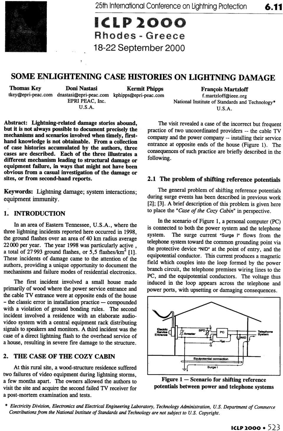
1 Some Enlightening Case Histories on Lightning Damage Thomas Key, Doni Nastasi and Kermit Phipps EPRI PEAC Corporation Knoxville TN François D. Martzloff National Institute of Standards and Technology Gaithersburg MD th Reprinted from Proceedings, 25 International Conference on Lightning Protection - Rhodes, September 2000 Significance: Part 6 - Textbook, tutorials and reviews This paper documents three case histories of damage caused to electronic systems and appliances for direct or nearby lightning strikes to residential structures. Complementary laboratory tests have been performed to narrow down the range of stresses to which the field-damaged equipment were submitted. These case histories also illustrate the consequences of incorrect bonding of utility connections to one residence, the sensitivity of dispersed electronic systems in the second residence, and incorrect routing of earthing conductors in the third residence.

2
3 In a laboratory replica of this configuration [2], a peak voltage of 4,3 kv was recorded across the two ports for a typical surge injected at the telephone entrance. A similar situation exists for a surge impinging on the video port of a TV receiver. The tests reported in 2.3 below show that this level can cause damage. 2.2 Cozy cabin site configuration In the Cozy Cabin installation, the power service entrance was located at one end of the house, while the cable TV service entrance was located at the opposite end. Furthermore, a visit to the site revealed that the cable TV shield was grounded only by a questionable ground rod next to the house foundation (within the drip line, and thus in dry soil, see Figure 2). This cable TV grounding electrode was not bonded to the grounding electrode of the power service entrance, a clear violation of the U.S. National Electrical Code ("NEC", NFPA 70, 1999) [4]. Following the visit to the site by the authors, the local cable TV company was informed of this situation and took what they believed an appropriate action: the incoming cable was first routed under the house, in the crawl space, to allow bonding the shield to the power service grounding connection. From there, the cable was returned to its original point of entry into the house, at the opposite end. This modification did correct the NEC violation but left the arrangement in the topology shown in Figure 1. However, the interaction was not pursued further with the cable company. A recommendation was made to the owner, to install a surge reference equalizer [5] for each piece of video equipment. After that was done, no damage occurred during the next lightning season. Of course, it is still too early to declare victory over Zeus and Murphy, but encouraging when compared to a previous history of two incidents within a few months. 2.3 Post mortem and surge tests One of the failed TV receivers from the Cozy Cabin was made available to the authors for examination. No evidence of damage was found on the power side of the chassis and the related components, but a clear indication of surface flashover was observed along the insulation of the gap intended to isolate the cable input 'ground' termination (connected to the incoming cable shield) from the shielding can of the tuner (connected to one of the power cord conductors, see Figure 3). After cleaning the carbonized path of the flashover, a 0,5 ps khz Ring Wave was applied in incremental steps between the two conductors of the power cord, bonded together, and the shield connector of the cable input: flashover occurred at 2 kv. By removing the material to a greater depth and covering it with epoxy, the gap did withstand a greater level, and failed at 2,5 kv. That flashover occurred at another part of the original insulation, thus providing valid information on the original - withstand capability Conclusions from the Cozy Cabin This case study illustrates the classic situation of separate service entrances, compounded with incorrect bonding. The examination and test demonstrate that at least 2,5 kv were developed across the power port and the cable TV port of the receiver under a condition of distant or nearby lightning strike Another significant finding from this case history is the anecdotal confirmation of allegations that cable TV installation practices prevailing in many residential situations might be in violation of the U.S. National Electrical Code. This violation made even more hazardous the now well-recognized occurrence of undesirable separation of the service entrances. I I. Incoming cable 2. Splitter & discharge unit I 3. Grounding wire 4. Ground rod I.Tuner box 2. Cable termination box 5.Watering can (for plants, not ground rod!) 3. Insulating gap 4. Incoming cable connection Figure 2 - Cable TV entrance Figure 3 - Insulating gap at signal input

4 3. INPUT ISOLATION PRACTICES Interest aroused by the Case of the Cozy Cabin led to a brief survey of what isolation schemes are applied by the manufacturers of video equipment. Televisions and VCRs are of a similar category of equipment in that they both have the same input ports: ac power, and video (antenna or cable), for which the 'ground' reference can be raised to different potentials during a surge event. The power port has no direct connection to the equipment grounding conductor because a two-prong ac plug is used. However, at the service entrance, the neutral - one of the two conductors of the cord - is bonded to the ground bus of the service panel. The video input is referenced to ground via a connection to a grounding rod outside the residence and (per the NEC [4]), a bonding conductor. Manufacturers use various techniques to isolate these two ports from each other inside the equipment. Surge tests were conducted on five televisions and three VCRs to determine the voltage level at which spark-over would occur between the power port and the video port. Using a 0,5 ps H z Ring Wave, incremental steps of 500 V were applied between the power port and the shield of the video input port. The units that had isolation built into the video port sparked-over at the series capacitor of the video port. The breakdown voltage level was approximately 2,5 kv in these units. Units in which the power supply outputs were electrically isolated from the inputs via transformers fared better. One sample survived and performed normally after all surge tests. Physical size of the transformer seemed to have some impact on the results. Larger transformers seemed to tolerate surges better than smaller ones. Based on this small number of VCR samples, a general observation is that VCRs use power supply transformers as isolation, similar to the newer TV sets, and do not have isolation between the cable or antenna input and the tuner chassis. This type of isolation scheme withstood higher surge voltages than the isolating ring that can be found in older television sets and serving to isolate the chassis of the set from the ('grounded') shield of the signal cable. 4. THE CASE OF THE RAMBLING RESIDENCE An expansive residential estate, located in the same general area as the Cozy Cabin, was the scene of a lightning incident where a tree adjacent to the house was struck (and subsequently died). Extensive damage was inflicted to the audio-video components that are connected to a central rack, and are located throughout the residence and its surroundings (large patio and swimming pool, with outdoor lighting and audio speakers). The home owners graciously allowed the authors to visit the residence and observe the configuration of the system in an attempt to better understand the mechanisms leading to the damage. They also made available to the authors the complement of damaged or presumed damaged equipment that had been replaced thanks to their insurance. Thus, this case history, unlike most lightning incidents, offered an unusual opportunity for documenting the process and consequences. Three activities were undertaken to better understand the mechanism and verify some hypotheses: Bench examination of returned equipment and surge testing of undamaged equipment; Site visit of the residence; Laboratory coupling of electric field stress into a remote speaker-to-amplifier connection. Bench Examination Bench tests for each electrical appliance began by plugging it into a 120-V a.c. outlet. Physical signs of normal operation were noted such as illuminated displays, response of controls, audiolvideo output. The equipment cover was removed for an internal inspection. In most of the equipment, physical damage such as a burned-out transistor was very apparent. Table 1 lists the home entertainment equipment that were submitted, and their condition. A signiticant finding was that all of the power supplies in the equipment were functional, indicating that the lightning surge either did not enter through the ac power port, or was not severe enough to cause damage to the power supplies. Table 1 Equipment submitted for bench tests a@. 1 Equipment Stereo tunerlamplifier - 3 Digital satellite system receiver Twelve-channel integration amplifier.- Indoor speaker -- - Indoor/outdoor speaker -- I Independent color TV receiver Condition Illuminated display was not working Damage to telephone control circuit Damage to power transistors Woofer damaged Woofer damage on all but two units - No damage -

5 The examination and, as appropriate, tests revealed the following conditions: Except for its non-operational display, the stereo tunerlamplifier appeared undamaged. The visible damage to the digital satellite receivers was nearly identical in all three units. Apparently, the surge had entered through the telephone port and had damaged the small surface-mount electronics that make up the modem circuit. However, because the satellite receivers could not be operated without their antenna and code-reading cards, the extent of the functional damage could not be determined The two 12-channel amplifiers had sustained damage to their output transistors that drive the speakers. The power supplies and fuses were not damaged. Furthermore, it was found that some speaker outputs were still operational. This situation suggested a possible mechanism that damaged only some of the output transistors, and therefore not attributable to a "power-line surge." In turn, that hypothesis was later verified by a laboratory test, as described in 4.3 below. Speakers, tested by connecting them to an amplifier that was known to be functioning properly, were found to have their woofers damaged, but the tweeters still operational. Other electrical appliances in the house including television sets and VCRs not connected to the centralized system were not included in the returned package and therefore presumed as not damaged. This fmding confii the conclusion that the long leads interconnecting the distributed system components acted as energy collectors, feeding the induced voltages or currents into the communications ports of the equipment. 4.2 Site Visit The purpose of the visit was to look for clues to explain the specific damage that was observed in some of the equipment. The following observations were made: Approximate distances between the lightning strike and affected equipment Location and grounding at the service entrances of cable TV, power, and telephone Other wiring and general installation practices The overall physical layout of the house, damaged tree, and electronic equipment are shown in Figure 4. The tree that was struck is much taller than the house and is the tallest of the trees in the immediate area. The bark was stripped from the tree trunk for most of its height. The tree trunk is only approximately 15 m from the house and even closer to the patio, where some of the audio speakers were installed. Outdoor speakers are also located in the pool area and connecting walkways. In the audio amplifiers, as noted above, the power supplies of the units were not damaged, but their output transistors that drive the speakers and the speakers themselves were damaged. Thus, it was speculated that the surge energy had been coupled into the speaker wires, which are probably very long and very near to the lightning strike, rather than as a "power-line surge." The visit to the installation verified this theory. The home entertainment equipment, including amplifiers, is centrally installed in the basement of the house. Speakers are iocared throughout rhe house, the patio, and the swimming pool area. The wire length between the outdoor speakers and the central amplifier is about 30 m, and some of the wires run within 10 m of the tree trunk. Cable and Utility terminals Telephone. Underground utilities Two-story house over basement Utilities entrance (Power, TV, Teleph Sprinkler controls 4 50 m (1 60 ft) * Figure 4 Schematic configuration of the Rambling Residence

6 4.3 Laboratory Coupling of Electric Field To validate the hypothesis of a failure mechanism involving the coupling of electric field energy into the speaker wire run, a qualitative laboratory test was staged, using the surviving channel of the amplifier to drive a speaker. An audio signal from a tape deck was fed into the amplifier input to monitor its operation during the test. A conventional Marx impulse generator at the NET High- Voltage Laboratory was used to apply a 1,2150 ps highvoltage field between two parallel plates, each 2 m x 1 m. A length of 5 m of speaker wire feeding the audio output from the system audio amplifier was sandwiched between the two plastic foam sheets separating the lower (grounded) plate, to which the amplifier chassis was bonded, from the upper (impulsed) plate. The effective length of the wire was increased by connecting to each wire a piece of foil of about 0,02 m2, simulating the increased capacitance effect of about 50 m of wire. Both the amplifier and tape deck were isolated from the power supply ground by an uninterruptible power supply. The impulse was applied in increments. At 70 kv, a flashover occurred between the two plate edges, but not involving the speaker wire. Immediate failure of the amplifier output circuit was noted. Frem this anecdote, we conclude that the rapid field change associated with the flashover did have the capability to couple enough surge energy into the capacitance divider of wirelground plane and cause destructive failure of the output transistor effectively connected across that capacitance. Such a scenario can be considered a reasonable emulation of the circumstances surrounding the "Lightning Incident at the Rambling Residence. " 4.4 Conclusions from the Rambling Residence The qualitative laboratory demonstration of coupling energy into the speaker wires provides one more piece of evidence that electronic appliances can be damaged by surges impacting their communications port, to the point that expecting protection by simple application of SPDs on the power port is not enough, and comprehensive protection is a necessity. In this case, there was no evidence of any damaging surge introduced by the power supply connection of the residence. 5. THE CASE OF THE STANDARD SUBURBAN 5.1 The aftermath In this case, which occurred in a suburban, semi-rural hilly area, the post-strike invest~gation revealed that the overhead service drop to the house (involving a span of about 20 m across the street) had been severed by melting at the point of strike. From there, the current traveled to the revenue meter (typically on the outside wall in U.S. practice), where a ground conductor is normally installed with a short run to the earthing electrode of the house. htead, according to the practice when constructed in the 1970s, a cold water pipe was allowed to be the main earthing electrode. In this case, the conductor for the earthing electrode entered the garage and was routed upward near the ceiling with several bends before it was bonded to a copper water pipe. Without any better path to earth, the lightning current had apparently followed the same route, severing the bare conductor while seeking the well-grounded water pipe (see Figure 5). North side West side Figure 5 - The Standard Suburban aftermath -- - Inside north wall
 plate, to which the")
7 As shown in the photographs of Figure 5, the service entrances were overhead and without any direct path to earth. This type of installation would not be approved by current US practice, which requires a direct connection to a driven ground rod in addition to any other supplemental electrodes such as the cold water pipe. One of the main reasons that the practice was modified is the growing use of PVC or plastic water pipe. On a later visit, the engineers who made the first visit were allowed to visit the repaired h6use. Indeed, the new service grounding point includes not only the electric power but also the telephone and cable company. The new water piping is PVC, and a driven ground rod has been installed as the primary grounding electrode. This new arrangement (Figure 6) reflects a recently issued recommended practice [6] which, in addition to the NEC minimum requirements for safety, calls for intersystem bonding of all utilities serving a residence, and this by having all the utility connections next to each other. The Care of the Rambling Residence and related tests illustrates that the often-cited "powerline surge" cause is not the only scenario responsible for appliance failures. Other ports of equipment, communication ports in particular, can be damaged by surges induced into the cables used for incoming or outgoing signals, and therefore need appropriate protection. The Case of the Standard Suburban shows that architects and builders have not fully understood the necessity of appropriate wiring and earthing practices. The same lack of understanding by some utility providers was also evident in the Case of the Cozy Cabin. The recommended practice of intersystem bonding at the service entrance described in this paper is compatible with the requirements of the U.S. National Electrical Code. Codes applicable in other countries might require a different arrangement, but the principles are the same. Ground To Senrice Panel INTERSYSTEM BONDING P Telephone Network lnterfacedevice\ Signal Input -- To Ground Rods J Figure 6 - Recommended intersystem bonding 5.2 Conclusion from the Standard Suburban Architects and builders, guided by up-to-date codes, can provide appropriate grounding practices in new construction. Surge-protective devices at the service entrance can provide a path from ungrounded conductors and equalize voltages between these conductors. The practice is recommended as the first level of protection from surges in the exterior electrical environment. 6. GENERAL CONCLUSIONS The Care of the Cozy W in and related tests confirm the need to pay attention to the problems associated with the surge protection of multi-port equipment. The solution of non-metallic communications media is not yet ready for the consumer market, but an effective mitigation approach is the surge reference equalizer. ACKNOWLEDGMENTS Resources for conducting these investigations were provided by the members of the Electric Power Research Institute. Lightning flash density data and comments on the manuscript were contributed by Kenneth Cummins of Global Atmospherics, Inc. The experiment on coupling energy into speaker wires, and a review of the manuscript were contributed by Gerald FitzPatrick. 8. REFERENCES [l] Personal communication, Global Atmospherics, Inc. [2] Key, T.S.. and Martzloff, F.D., "Surging the Upside-Down House: Looking into Upsetting Reference Voltages," Proceedings, PQA '94 Conference, Amsterdam, October [3] Martzloff, F.D., Mansoor, A., Phipps, K.O., and Grady, W.M., "Surging the Upside-Down House: Measurements and Modeling Results," Proceedings, PQA'95 Conference, May [4] NFPA , National Electrical Code, National Fire Protection Association, [5] IEEE Std (Emerald Book) IEEE Recommended Practice for Powering and Grounding Electronic Equipment, IEEE, [6] EPRI PEAC, Recommended Practice for Protecting Residential Structures and Appliances Against Surges, Report PEAC.0545.R, EPRI PEAC Corporation, Knoxville, TN, 1999.

Update on a Consumer-Oriented Guide for Surge Protection
 Update on a Consumer-Oriented Guide for Surge Protection Thomas Key, Doni Nastasi, and Kermit Phipps EPRI PEAC François Martzloff National Institute of Standards and Technology Jim May Illinois Power Company
Lightning Arresters P30027 18 KVA P30038 10 KVA. Description & Installation
 Lightning Arresters P30027 18 KVA P30038 10 KVA Description & Installation Printed in USA 09/11 TO330 Rev. B Table of Contents Page 1.0 SCOPE 2 2.0 PRODUCT OVERVIEW 2 2.1 Intended Uses 2 2.2 Lightning
Coaxial Cable Entry Panels, Coax and Grounding Connectors. Technical Note
 Coaxial Cable Entry Panels, Coax and Grounding Connectors Technical Note Coaxial Cable Entry Panels, Coax and Grounding Connectors Surge Protection Solutions for PTC 2 Coaxial Cable Entry Panels, Coax
MISCELLANEOUS ELECTRICAL JOBS REQUIRING PERMITS
 MISCELLANEOUS ELECTRICAL JOBS REQUIRING PERMITS 01. SAFETY INSPECTION of service equipment at FPL Power Source 02. Construction GFI power outlets (Temp Pole for Construction) 03. 90 day temporary power
800 Communications Circuits
 ARTICLE 800 Communications Circuits INTRODUCTION TO ARTICLE 800 COMMUNICATIONS CIRCUITS This article has its roots in telephone technology. Consequently, it addresses telephone and related systems that
Grounding of Electrical Systems NEW CODE: Grounding and Bonding
 Grounding of Electrical Systems NEW CODE: Grounding and Bonding Presented By Scott Peele PE Grounding of Electrical Systems Outline Defining the Terms Why should I Ground? Types of Grounding Systems Separately
Transformer Deluge Systems
 Transformer Deluge Systems How Do Transformer Fires Ignite? Common causes of transformer failure: Weather-related events such as lightning Short circuits in electrical equipment The most common cause is
CHAPTER 4 UTILITY SYSTEMS ELECTRICAL. Utility Systems Electrical. Main Panel
 CHAPTER 4 UTILITY SYSTEMS ELECTRICAL Utility Systems Electrical The electrical supply to your home begins outside, where you will see either an overhead feed and piping down the side of your home or (if
Please check with your local inspection authority for any additional requirements before installation.
 Specifications for Residential Overhead Electric Service Installation This brochure addresses most typical residential overhead service installations. Variances for the following specifications must be
Protect your home and family with Advanced Technology from Cutler-Hammer
 Protect your home and family with Advanced Technology from Cutler-Hammer Residential Home Fire Statistics Annually - over 415,000 Residential Fires Annually - over 40,000 electrical fires over 350 deaths
Chapter 9. Bonding and Grounding
 Chapter 9 Bonding and Grounding Objectives Describe why the cable should be bonded Describe bonding and grounding procedures Define Bonding and Grounding Explain Safety Benefits and intent of bonding and
2014 NEC Guide Lines for Home Owner Doing Electrical Work on their Property
 2014 NEC Guide Lines for Home Owner Doing Electrical Work on their Property A brief summary of the most used code references for residential wiring State of Idaho Division of Building Safety Electrical
Application Bulletin 103 - NEC Reference Guide for SolarBridge-Enabled AC Module Installers
 9229 Waterford Centre Dr. Bldg C, Suite 110 Austin, Tx 78758 Application Bulletin 103 - NEC Reference Guide for SolarBridge-Enabled AC Module Installers Current Version: 13 AC Modules are a new product
Video Camera Installation Guide
 Video Camera Installation Guide The intent of this guide is to provide the information needed to complete or modify a video camera installation to avoid lightning and induced power surge damage. This guide
Home Gateway. User s Installation Guide. In This Guide
 Explorer 4250 Home Gateway User s Installation Guide In This Guide Safety Information... 2 Safety First... 6 Explorer eclub... 6 Explorer 4250 Home Gateway Serial Number... 6 What s On the Front Panel?...
ELECTRICAL INSPECTION BULLETIN (Effective 2000-03-01)
") ELECTRICAL INSPECTION BULLETIN (Effective 2000-03-01) Rule 28-900 Standby Generator Installations Due to the increasing number of standby generator installations being established to maintain continuity
ELECTRICAL INSPECTION BULLETIN (Effective 2000-03-01) Rule 28-900 Standby Generator Installations Due to the increasing number of standby generator installations being established to maintain continuity
CONSTRUCTION STANDARD ELECTRIC OPERATIONS ORGANIZATION
 Page 1 of 11 ****This Standard Supercedes BECo CS2.13-2.3 & ComElectric OH Construction Manual, System Grounding Section, drawings CGND, GRDSUM, and C2**** 1.0 Bill of Materials GROUNDING AND BONDING POLE-MOUNTED
Electrical for Detached Garages: Updated Feb 19, 2016 for 2015 CE Code in force Jan. 1, 2016. Underground branch circuit feeding a detached garage:
 Electrical for Detached Garages: Updated Feb 19, 2016 for 2015 CE Code in force Jan. 1, 2016 * Garage construction requires permits (electrical, building) * Permits must be applied for at the time. * Dial
County of Riverside Building and Safety Department
 County of Riverside Building and Safety Department Mike Lara Director Photovoltaic Permitting Guidelines The information provided in this document is general and is intended only as a guide. Each project
Residential Electrical System Aging Research Project. Dave Dini Sr. Research Engineer Underwriters Laboratories
 Residential Electrical System Aging Research Project Dave Dini Sr. Research Engineer Underwriters Laboratories Aging Residential Electrical Systems Research Project Sponsors Fire Protection Research Foundation
LF-IRX. Limited Warranty LF-IRX. Remote Control Extender OWNER S MANUAL
 Limited Warranty OWNER S MANUAL Audiovox Corporation (Audiovox) warrants this product against defects in materials or workmanship for one (1) year from the date of purchase. During this period, this product
Grounding & Bonding Why it is done And How to Install Properly
 Grounding & Bonding Why it is done And How to Install Properly The technical information provided herein is to assist qualifi ed persons in planning and installing electric service to farms and residences.
Cat7/Class F New Installation Concept New infrastructure. Handbook
 Cat7/Class F New Installation Concept New infrastructure Handbook contents 1 Introduction 3 2 What is the Cat7/Class F installation concept 3 3 Distribution centre 3 3.1 Patch Modules 3 4 How to handle
IMMS-CCC. IMMS-CCC Hardwire Central Interface. Installation Instructions
 IMMS-CCC IMMS-CCC Hardwire Central Interface Installation Instructions TABLE OF CONTENTS... Choose a Location... 1 Connections... 2 Operations... 3 Software Configuration... 4 Troubleshooting... 5 Loopback
Top Commercial / Residential Electrical Requirements *
 Department of Community Development Building Division 4800 West 92 nd Avenue Westminster, Colorado 80031 For Information call (303) 658-2075 Fax (303) 706-3922 www.westminsterpermits.com Top Commercial
Electrical Code Regulation
 Electrical Code Regulation St. Clair County has adopted the 2005 National Electrical Code in its entirety for the unincorporated areas of the county and all communities that have contracted with the county
Presenters Brett Weiss, Gabe Martinez, Brian Kroeger.
 1 Presenters Brett Weiss, Gabe Martinez, Brian Kroeger. Topics to be covered: Cable identification Purpose of the various cable types Installation techniques Building Infrastructure Overview of networking
Guidance on Proper Use of EXTENSION CORDS, POWER STRIPS & SURGE PROTECTORS
 Guidance on Proper Use of EXTENSION CORDS, POWER STRIPS & SURGE PROTECTORS The Language Used In This Document Does Not Create An Employment Contract Between The Employee And The Agency. This Document Does
PT-6000 Power Tower INSTALLATION MANUAL SPECIFICATIONS
 PT-6000 Power Tower INSTALLATION MANUAL 10.5 9.75 12 22.75 10.75 MAXIMUM SOIL HEIGHT: DO NOT ALLOW FILL TO EXCEED THIS LEVEL! 11.5 4 4 13 Optional PT-BASE for new installations or when previous 2000/6000
ALUMINUM ELECTRICAL WIRING
 ALUMINUM ELECTRICAL WIRING prepared by Fire Prevention and Investigation Division Denver Fire Department Department of Safety and Electrical Inspections Section Denver Building Inspection Division Community
www.klmtechgroup.com TABLE OF CONTENT
 Page : 1 of 13 Project Engineering Standard www.klmtechgroup.com KLM Technology #03-12 Block Aronia, Jalan Sri Perkasa 2 Taman Tampoi Utama 81200 Johor Bahru Malaysia ELECTIRAL GROUNDING TABLE OF CONTENT
AN-6 COMMON MISTAKES IN LIGHTNING PROTECTION OF PHONE LINE INTERFACE CIRCUITS
 AN-6 COMMON MISTAKES IN LIGHTNING PROTECTION OF PHONE LINE INTERFACE CIRCUITS By Joe Randolph Introduction Lightning protection of phone line interface circuits is a complicated topic. The specific protection
AVR 158. Audio/video receiver. Quick-Start Guide ENGLISH
 158 Audio/video receiver ENGLISH Quick-Start Guide 158 Introduction, Speaker Placement and Connection Introduction Thank you for choosing a harman kardon product! This quick-start guide contains all the
GROWTH MANAGEMENT DEPARTMENT 201 SE 3 rd ST, (Second Floor), Ocala, FL 34471 (352) 629-8421; FAX: (352) 629-8264
, Ocala, FL 34471 (352) 629-8421; FAX: (352) 629-8264") BUILDING CODE GUIDELINES FOR ELECTRICAL INSPECTIONS Building Code compliance is the obligation of design professionals and/or contractors. Plan Review and Inspection Guidelines are intended to be used
BUILDING CODE GUIDELINES FOR ELECTRICAL INSPECTIONS Building Code compliance is the obligation of design professionals and/or contractors. Plan Review and Inspection Guidelines are intended to be used
Exploring the Necessity of the Hot Hipot Test
 Exploring the Necessity of the Hot Hipot Test Introduction In an industry comprised of workers with varying electronics knowledge, a Hipot test can seem a daunting task for some. Indeed, many test operators
Grounding Demystified
 Grounding Demystified 3-1 Importance Of Grounding Techniques 45 40 35 30 25 20 15 10 5 0 Grounding 42% Case 22% Cable 18% Percent Used Filter 12% PCB 6% Grounding 42% Case Shield 22% Cable Shielding 18%
BOSE. Link AL8 HOMEWIDE WIRELESS AUDIO LINK
 BOSE Link AL8 HOMEWIDE WIRELESS AUDIO LINK Français English SAFETY INFORMATION Please read this owner s guide Please take the time to follow the instructions in this owner s guide carefully. It will help
POWER QUALITY IN YOUR HOME
 POWER QUALITY IN YOUR HOME How to ensure the life and reliable operation of your home electronics Electricity provides the power you need to run your home electronic equipment. Sometimes, interference
City of Riverside Building & Safety Division Phone: (951) 826-5697 www.riversideca.gov
 826-5697 www.riversideca.gov") City of Riverside Building & Safety Division Phone: (951) 826-5697 www.riversideca.gov PHOTOVOLTAIC PERMITTING GUIDELINES The information provided in this document is general and is intended only as a
City of Riverside Building & Safety Division Phone: (951) 826-5697 www.riversideca.gov PHOTOVOLTAIC PERMITTING GUIDELINES The information provided in this document is general and is intended only as a
Lynx Broadband Installation Manual for Residential Packages with a 20 db Amp Quick Start Guide (first two pages)
") Lynx Broadband Installation Manual for Residential Packages with a 20 db Amp Quick Start Guide (first two pages) 1. Be sure that your kit includes all the parts shown in the Check the Equipment section
Lynx Broadband Installation Manual for Residential Packages with a 20 db Amp Quick Start Guide (first two pages) 1. Be sure that your kit includes all the parts shown in the Check the Equipment section
RESIDENTIAL ELECTRICAL REQUIREMENTS (REVISED 3/28/2008) PERMIT REQUIREMENTS:
 PERMIT REQUIREMENTS:") RESIDENTIAL ELECTRICAL REQUIREMENTS (REVISED 3/28/2008) PERMIT REQUIREMENTS: Signed completed Electrical Permit application form. Minnesota law requires all electrical work is to be performed by licensed,
RESIDENTIAL ELECTRICAL REQUIREMENTS (REVISED 3/28/2008) PERMIT REQUIREMENTS: Signed completed Electrical Permit application form. Minnesota law requires all electrical work is to be performed by licensed,
Transient and Lightning Protection for the Water Industries
 Transient and Lightning Protection for the Water Industries Mike Nager Phoenix Contact mnager@phoenixcon.com 5 th ISA Water/Wastewater Automatic Controls Division Symposium (WWAC) August 3-5, Orlando,
How To Plan Out An Array Of Solar Panels
 CITY OF DOWNEY COMMUNITY DEVELOPMENT, BUILDING AND SAFETY 11111 Brookshire Avenue Downey, CA 90241 562.904.7142 (www.downeyca.org) B SECTION 01/01/2011 EFFECTIVE DATE PHOTOVOLTAIC 032 FORM NUMBER 2013
What are the basic electrical safety issues and remedies in solar photovoltaic installations?
 What are the basic electrical safety issues and remedies in solar photovoltaic installations? Presented by: Behzad Eghtesady City of Los Angeles Department of Building and Safety Topics Covered Photovoltaic
LOXONE 12 Channel Amplifier
 LOXONE 12 Channel Amplifier Item no.: 200110 Thank you for purchasing the Loxone Twelve Channel Amplifier. The versatility of the Amplifier makes it the perfect choice for almost every type of custom multi-room
Product Safety Considerations for Insulation Coordination of Low- Voltage Equipment. Scott Aldous, Compliance Engineer
 Product Safety Considerations for Insulation Coordination of Low- Voltage Equipment Scott Aldous, Compliance Engineer What is Insulation Coordination? From IEC 60664-1, Edition 1.2: So what does that mean
Electrical. This section applies to the design and installation of building power distribution systems.
 Basis of Design This section applies to the design and installation of building power distribution systems. Design Criteria This section contains the architectural, structural and mechanical provisions
1. Franklin Rod Performance 2. LEC/DAS Performance
 THREE ESSENTIALS OF LIGHTNING PROTECTION: BONDING, GROUNDING AND SURGE PROTECTION by Richard Kithil, President and Orlando Alzamora, Vice-President National Lightning Safety Institute (NLSI) 1.0 Summary.
Grounding Practice at Data and Communications Centers. David Brender, P.E., CPQ National Program Manager Copper Development Association Inc.
 Grounding Practice at Data and Communications Centers David Brender, P.E., CPQ National Program Manager Copper Development Association Inc. Overview of This Presentation Elements of building wiring and
Siemens Energy & Automation. structured. WIRING Product Training Series: Advanced Video Session 3
 s structured WIRING Product Training Series: Advanced Video Session 3 1 Table of Contents This presentation will give you a closer look at Video in Structured Wiring applications. The following Areas will
Guide to the electrical parameter classifications of IEC 60950 and IEC 62368 safety standards
 Guide to the electrical parameter classifications of IEC 60950 and IEC 62368 safety standards Abstract This Guide is an informative listing of selected terms and definitions found in IEC Glossary entry
David Brender Copper Development Association Inc. david.brender@copperalliance.us. Miramar, March 8, 2013
 Grounding and Bonding in Communications Systems David Brender Copper Development Association Inc. david.brender@copperalliance.us Ennes Workshop Miramar, March 8, 2013 MMXIII This talk concentrates on:
EARTHING AND BONDING AT SECONDARY SUBSTATIONS
 DISTRIBUTION CONSTRUCTION MANUAL SECTION 4 - SUBSTATIONS ISSUE B SEPT 1996 4.4.4 EARTHING AND BONDING AT SECONDARY SUBSTATIONS 1 SCOPE This section of the Distribution Construction Manual lays down the
Connections and Setup
 12 Connections and Setup HOW TO CONNECT YOUR SATELLITE RECEIVER Use the information in this chapter to connect your receiver to other equipment. CONNECTING TO THE NEARBY HDTV (TV1) CONNECTING TO THE REMOTE
DPS Preliminary Review: Verizon FIOS Customer Premises Installation NEC Compliance Issues
 DPS Preliminary Review: Verizon FIOS Customer Premises Installation NEC Compliance Issues OVERVIEW A key aspect of providing telecommunications services is the provision of those services in a safe and
Our data centres have been awarded with ISO 27001:2005 standard for security management and ISO 9001:2008 standard for business quality management.
 AIMS is Malaysia and South East Asia s leading carrier neutral data centre operator and managed services provider. We provide international class data storage and ancillary services, augmented by an unrivaled
************* OWNER'S MANUAL BAMF800/2 BAMF1250/2 BAMF1800/2 BAMF2200/2 BAMF2600/2 BAMF1200/4 BAMF1600/4 BAMF2000/1D BAMF4000/1D BAMF5500/1D
 ************* OWNER'S MANUAL BAMF800/2 BAMF1250/2 BAMF1800/2 BAMF2200/2 BAMF2600/2 BAMF1200/4 BAMF1600/4 BAMF2000/1D BAMF4000/1D BAMF5500/1D INTRODUCTION Power Acoustik amplifiers provide high-performance
Specifying an IT Cabling System
 Specifying an IT Cabling System This guide will help you produce a specification for an IT cabling system that meets your organisation s needs and gives you value for money. You will be able to give your
ELECTRICAL GUIDELINES FOR SINGLE-FAMILY HOME OWNERS:
 ELECTRICAL GUIDELINES FOR SINGLE-FAMILY HOME OWNERS: Chapter 12 of the Burlington Code of ordinances allows owner occupants of single family homes to do their own wiring if they choose. If you choose to
Model 1756 Test Lead Kit
 Keithley Instruments 28775 Aurora Road Cleveland, Ohio 44139 1-888-KEITHLEY http://www.keithley.com Model 1756 Test Lead Kit Gerneral Purpose Test Lead Information Description These test leads allow you
INSPECTION GUDELINES
 GENERAL REQUIREMENTS Building permit and approved set of plans Building permit on the card is the same as on the route "If this is not the first inspection, read inspection records and notes on permit
Lightning current simulation in the laboratory - parameters, procedures and test equipment -
 Lightning current simulation in the laboratory - parameters, procedures and test equipment - Dipl.-Ing. J. Schönau, Dr.-Ing. M. Naß, CE-LAB GmbH Prof. Dr.-Ing. F. Berger, Ilmenau University of Technology
VIEW. SLX300 SpeakerLinX IP Zone. Amplifier Installation and Setup Guide. AVoIP
 VIEW SLX300 SpeakerLinX IP Zone Amplifier Installation and Setup Guide TM AVoIP ClearOne 5225 Wiley Post Way Suite 500 Salt Lake City, UT 84116 Telephone 1.800.283.5936 1.801.974.3760 Tech Sales 1.800.705.2103
Wiser Panel Meter, Model Number WISERCTPM200 Installer s Guide
 Instruction Bulletin EAV85226 08/2014 Wiser Panel Meter, Model Number WISERCTPM200 Installer s Guide Retain for future use. Product Description Kit Contents The Wiser Panel Meter is for use in energy management
Project Name: Nortrax Section 26 41 00 Project No: 13-013 SURGE PROTECTION DEVICES Page 1
 Page 1 PART 1 - GENERAL 1.1 RELATED DOCUMENTS A. General: Drawings and general provisions of the Contract, including General and Supplementary Conditions and Divisions 1 Specification sections apply to
INTERNATIONAL STANDARD
 INTERNATIONAL STANDARD IEC 62305-3 Edition 2.0 2010-12 colour inside Protection against lightning Part 3: Physical damage to structures and life hazard INTERNATIONAL ELECTROTECHNICAL COMMISSION PRICE CODE
LDG DTS-4/4R Desktop Coaxial Switch / Remote
 LDG DTS-4/4R Desktop Coaxial Switch / Remote LDG Electronics 1445 Parran Road, PO Box 48 St. Leonard MD 20685-2903 USA Phone: 410-586-2177 Fax: 410-586-8475 ldg@ldgelectronics.com www.ldgelectronics.com
PORTABLE GENERATORS AND OSHA CONSTRUCTION REGULATIONS
 PORTABLE GENERATORS AND OSHA CONSTRUCTION REGULATIONS Monograph by: John Grizzy Grzywacz, Professor OSHA National Training Institute Arlington Heights, Illinois Contributing: Michael Kovacic, President
Copper Applications A Case Study
 Copper Applications A Case Study P O W E R Q U A L I T Y Florida Credit Union Data Center Shrugs Off Direct Lightning Hit Solid Copper Grounding System, In-Depth Surge Protection Keep System On-Line http://www.copper.org
Generic - Hearing Loop - (AFILS) U.S. System Specification
 U.S. System Specification") This document is a generic specification for any Hearing Loop (Audio Frequency Induction Loop System). For the remainder of the document, we will refer to using the term Hearing Loop rather than Audio
This document is a generic specification for any Hearing Loop (Audio Frequency Induction Loop System). For the remainder of the document, we will refer to using the term Hearing Loop rather than Audio
**ATTENTION** WE DO NOT PROMOTE OR ENCOURAGE YOU TO DO YOUR OWN ELECTRICAL WIRING!!! IT IS BY FAR THE MOST DANGEROUS THING YOU CAN ATTEMPT
 **ATTENTION** WE DO NOT PROMOTE OR ENCOURAGE YOU TO DO YOUR OWN ELECTRICAL WIRING!!! IT IS BY FAR THE MOST DANGEROUS THING YOU CAN ATTEMPT. YOU COULD PUT YOUR FAMILY AND WORLDLY POSSESSIONS IN DANGER!!!
ELECTRICAL ENGINEERING DESIGN CRITERIA APPENDIX F
 ELECTRICAL ENGINEERING DESIGN CRITERIA APPENDIX F TABLE OF CONTENTS Appendix F - Electrical Engineering Design Criteria F.1 Introduction...F-1 F.2 Codes and Standards...F-1 F.3 Switchyard and Transformers...F-1
ONT Installation Practices
 An ADTRAN White Paper ONT Installation Practices Author: Jim Wiese Senior Compliance Engineer ONT Installation Practices: Managing factors that can cause undesired lightning related transients on ONT customer
White Paper: Electrical Ground Rules
 Acromag, Incorporated 30765 S Wixom Rd, Wixom, MI 48393 USA Tel: 248-295-0880 Fax: 248-624-9234 www.acromag.com White Paper: Electrical Ground Rules Best Practices for Grounding Your Electrical Equipment
PS 29M DUAL CHANNEL BELTPACK IN METAL CASE
 PS 29M DUAL CHANNEL BELTPACK IN METAL CASE USER MANUAL October 2013 This product is designed and manufactured by: ASL Intercom BV Zonnebaan 42 3542 EG Utrecht The Netherlands Phone: +31 (0)30 2411901 Fax:
Interfacing electrification and system reliability. Earthing of AC and DC railways 4,10,13
 Interfacing electrification and system reliability Roger White Professional Head of Electrification and Plant Rail Abstract Integration is the term given to ensuring that the different elements of an electrified
ELECTRICAL SAFETY. The standard unit for measuring electrical current.
 ELECTRICAL SAFETY Introduction The following sections provide general safety guidelines and procedures for electrical safety. This chapter covers the following topics: TOPIC PAGE General Electrical Safety
270526-TC Grounding and Bonding for Telecommunications Systems
 270526-TC Grounding and Bonding for Telecommunications Systems Part 1 - General Related Documents The following related sections of the OT standards shall also be applicable to this section. OT Engineer
BASIC NEC CODE RULES AND DESIGN PRACTICE
 BASIC NEC CODE RULES AND DESIGN PRACTICE Wire Ampacity and Size Circuit Breaker Size 1. Maximum loading for any branch circuit is 80% of rating of circuit for ampacity of wire for any load. NEC 220-2,
PXL-250: Network Wiring
 This document provides the network wiring requirements for a PXL-250 access control network. Network Requirements The PXL-250 uses a half-duplex, RS-485 communication bus. Per the RS-485 specification,
Specifications for Lightning Protection. ASAE Engineering Practice
 Chapter 8: Lightning Specifications for Lightning Protection ASAE safety standards are not laws. They are recommended voluntary standards used by designers, engineers, manufacturers and users of the equipment,
STREETLIGHT SYSTEM GROUNDING AND BONDING
 Page: 1 of 8 STREETLIGHT SYSTEM GROUNDING AND BONDING 1. Scope This Construction Standard covers the grounding and bonding requirements for single phase streetlight systems served by the Looped Radial
Security Cameras, CATV, GPS & Satellite Protection. White Paper
 Security Cameras, CATV, GPS & Satellite Protection White Paper Security Cameras, CATV, GPS & Satellite Protection Surge Protection Solutions for PTC 1 Security Cameras, CATV, GPS & Satellite Protection
HOUSTON COMMUNITY COLLEGE HCC ALIEF CAMPUS MAIN BUILDING, FIRST, SECOND & FOURTH FLOORS RENOVATION ISSUE DATE: 10.17.12
 SECTION 27 05 26 - GROUNDING AND BONDING FOR COMMUNICATIONS SYSTEMS PART 1 - GENERAL 1.1 SUMMARY A. This Section includes grounding and bonding products, design requirements and installation for communications
Telecommunication Line Protectors
 TN CR 0025 Telecommunication Line s 1.1 The nature of telecom surges The telecom services considered in this report are transported on twisted pair. Each service has two wires, or lines, sometimes called
3.1.1 Full Type Tests & Routine Tests according to Clause 8 2 & 8 3. 4.0 Instructions For Installation, Operation & Maintenance
 SPECIFICATION FOR LOW VOLTAGE SWITCHBOARD SEN I N D E X Description 10 STANDARD TECHNICAL REQUIREMENTS 11 Standards 12 General Operating Conditions 13 General Description Of Switchboard 131 Structure 132
Cable Discharge Event
 Cable Discharge Event 1.0 Introduction The widespread use of electronic equipment in various environments exposes semiconductor devices to potentially destructive Electro Static Discharge (ESD). Semiconductor
Qualitative Analysis of Power Distribution Configurations for Data Centers
 Qualitative Analysis of Power Distribution Configurations for Data Centers White Paper #4 2007 The Green Grid. All rights reserved. No part of this publication may be used, reproduced, photocopied, transmitted,
Aerial Fibre Optics. Complete One Stop Solution for Aerial Fibre Optics. OPGW Cable and Fittings for OPGW
 Complete One Stop Solution for OPGW Cable and Fittings for OPGW 53, Justice Chandra Madhav Road, Kolkata - 700020. India. Phone: 91-33-24748575 / 7565 Fax: 91-33-2476-1955 Email: sales@supremeco.com Website:
EH-20 20m antenna. By VE3RGW
 EH-20 20m antenna By VE3RGW Equivalent circuit of EH-20 (prototype 2A) antenna system. Upper cylinder Lower cylinder Ground Counter pose Phasing coil Impedance transformer and tune circuit Tune coil Feed
INDUSTRY WIDE LABOR-MANAGEMENT SAFETY COMMITTEE SAFETY BULLETIN #23
 INDUSTRY WIDE LABOR-MANAGEMENT SAFETY COMMITTEE SAFETY BULLETIN #23 GUIDELINES FOR WORKING WITH PORTABLE POWER DISTRIBUTION SYSTEMS AND OTHER ELECTRICAL EQUIPMENT "ADDENDUM C" WORKING WITH 480 VOLT SYSTEMS
Lightning Protection for Comrex Equipment
 Lightning Protection for Comrex Equipment Lightning protection is not an exact science: You can follow all the rules and still lose equipment in a severe storm. This paper attempts to separate the desired
emta (VoIP over Cable Modem)
") emta (VoIP over Cable Modem) User Manual Version 1.0 Important Rules for Safe Operation Safe Use of Equipment Read all the instructions before operating this equipment with particular emphasis to safety
emta (VoIP over Cable Modem) User Manual Version 1.0 Important Rules for Safe Operation Safe Use of Equipment Read all the instructions before operating this equipment with particular emphasis to safety
Split-type Air-Conditioner INSTALLATION MANUAL CONTENTS FOR INSTALLER MXZ-3A30NA MXZ-4A36NA ATTENTION. English. Français. Español
 Split-type Air-Conditioner MXZ-3A30NA MXZ-4A36NA INSTALLATION MANUAL Refer to the installation manual of each indoor unit for indoor unit installation. English Français Español ATTENTION This manual mentions
HOUSING QUALITY STANDARDS (HQS)
") HOUSING QUALITY STANDARDS (HQS) Series 5 Electrical Safety And INSPECTIONS 5.01 ELS Revised 8-17-06 Electricity is Dangerous All electrical repairs should be made by licensed professionals. Touching any
HOUSING QUALITY STANDARDS (HQS) Series 5 Electrical Safety And INSPECTIONS 5.01 ELS Revised 8-17-06 Electricity is Dangerous All electrical repairs should be made by licensed professionals. Touching any
DEHN + SÖHNE. DEHNconductor System No Problems with Proximities
 DEHN + SÖHNE DEHNconductor System No Problems with Proximities DEHNconductor System - New Possibilities for controling Proximities. For preventing dangerous flashovers among parts of external lightning
The Do s and Don ts of Pressure Transducers
 The Do s and Don ts of Pressure Transducers ABSTRACT When specifying a pressure transducer for a process measurement, a number of items have to be considered. Some of the more important ones are discussed
White Paper SolarEdge Three Phase Inverter System Design and the National Electrical Code. June 2015 Revision 1.5
 White Paper SolarEdge Three Phase Inverter System Design and the National Electrical Code June 2015 Revision 1.5 Shalhevet Bar-Asher; SolarEdge Technologies, Inc. Bill Brooks, PE; Brooks Engineering LLC
IMPORTANT SAFETY INSTRUCTIONS
 IMPORTANT SAFETY INSTRUCTIONS Before you install or use the apparatus, you must read and understand these Important Safety Instructions. At all times when using the apparatus you must follow these Important
2a. IEM Indoor Metal Clad Medium Voltage Switchgear 15KV 16346-1. 2a. Section 16346 INDOOR METAL CLAD MEDIUM VOLTAGE SWTICHGEAR (Std.
 2a. IEM Indoor Metal Clad Medium Voltage Switchgear 15KV 16346-1 2a. Section 16346 INDOOR METAL CLAD MEDIUM VOLTAGE SWTICHGEAR (Std. Relays) Part 1 General 1.1 CONDITIONS AND REQUIREMENTS: A. Refer to