USER MANUAL HANDBUCH HANDLEIDING MANUEL DESCRIPTIF РУКОВОДСТВО ПОЛЬЗОВАТЕЛЯ КЕРІВНИЦТВО КОРИСТУВАЧА CHM-02
|
|
|
- Charity Rose
- 8 years ago
- Views:
Transcription
1 CHM-02 USER MANUAL HANDBUCH HANDLEIDING MANUEL DESCRIPTIF РУКОВОДСТВО ПОЛЬЗОВАТЕЛЯ КЕРІВНИЦТВО КОРИСТУВАЧА COMPUTER HEALTH MONITOR PCI CARD COMPUTER KONTROLLMONITOR FÜR DEN PCI-STECKPLATZ DIAGNOSTISCHE PCI KAART L'ORDINATEUR CONTRÔLE DE LA CARTE PCI ДИАГНОСТИЧЕСКАЯ PCI-КАРТА ДЛЯ МАТЕРИНСКОЙ ПЛАТЫ КОМПЬЮТЕРА ДІАГНОСТИЧНА PCI-КАРТА ДЛЯ МАТЕРИНСЬКОЇ ПЛАТИ КОМП'ЮТЕРА

2 Features Designed for PCI slot of any motherboard Shows power supply unit status Indicates status of all interfaces and ports Error codes on the LED display help to pinpoint the assembly problems Specifications BIOS version supported: PHOENIX v ; AMI v.6.24; AWARD v.4.5 Indicators: 8 color LEDs and 2-digit LED display PCI bus version supported: 3.3 V 32/64 bit Dimensions: 80 x 58 x 10.5 mm Net weight: 25 g 2

3 3

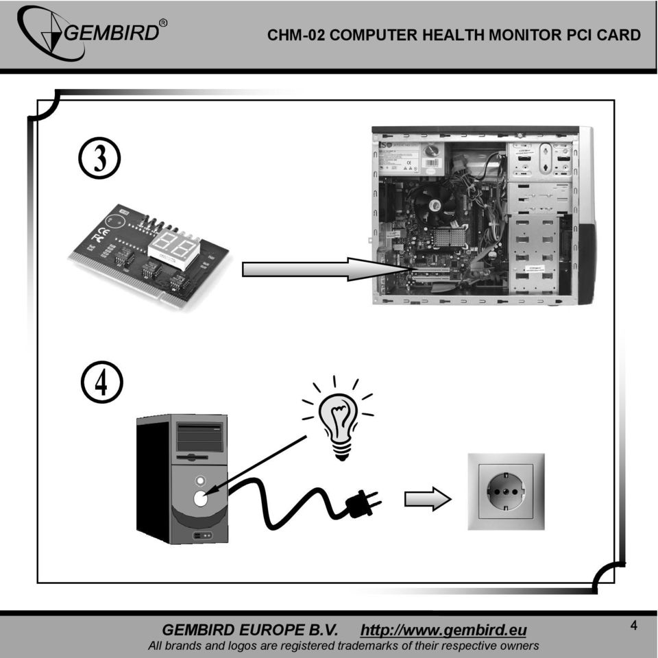
4 4
5 5

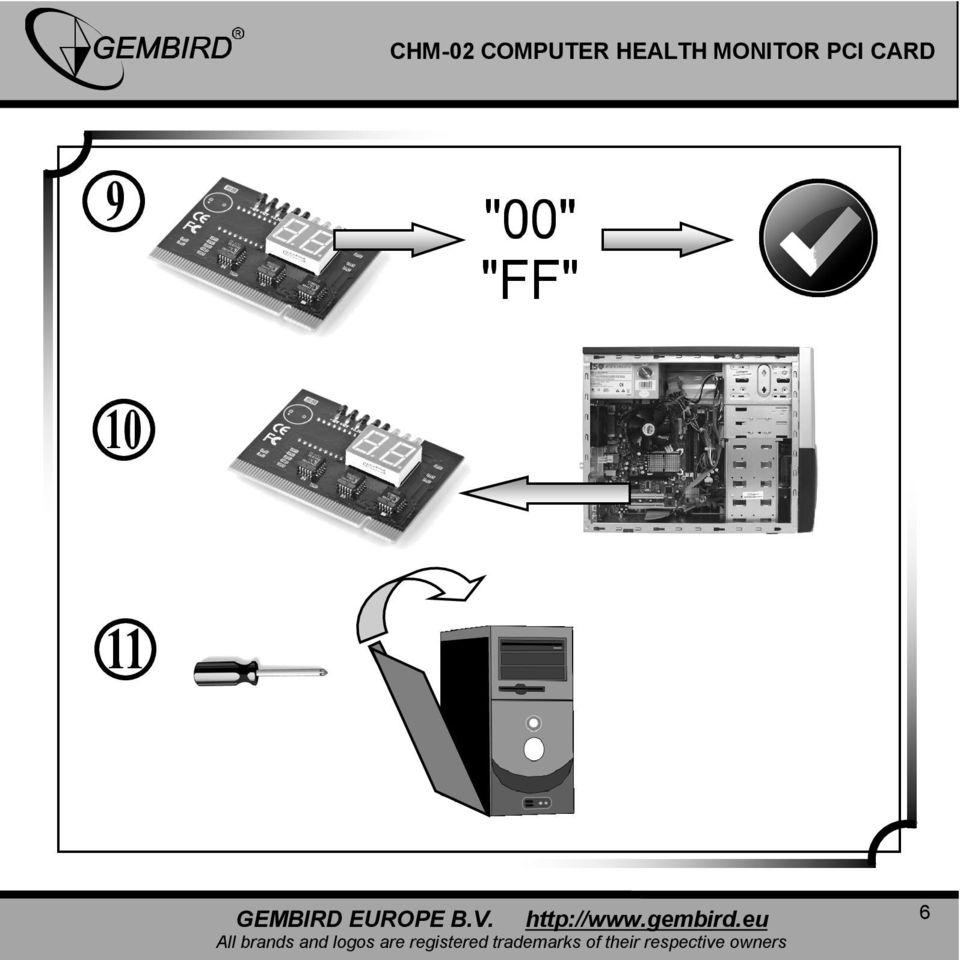
6 6
7 CHM-02 COMPUTER HEALTH MONITOR PCI CARD Hexadecimal character table LEDs description -12V (red) +12 V (Red) +3,3 V (Red) +5V (Red) CLOCK (Red) FRAME (Green) IRDY (Green) RESET (Green) 7
 FRAME (Green) IRDY (Green) RESET")
8 Table #1 - LEDs description LED Color Description +5V Red +3.3V Red Lit up whenever the motherboard is powered on with +5V voltage. If it is not lit up then it should be either the power supply fault or short circuit on the motherboard The same as "+5V. It is not lit up when the voltage 3.3V is not available on the motherboard +12V Red The same as "+5V -12V Red The same as "+5V CLOCK Red CPU clock adjustment is without problems whenever this LED is lit up FRAME Green Flashing whenever PCI "FRAME" signal is active IRDY Green Flashing whenever PCI "IRDY" signal is active RESET Green This LED should be lit up only during the reset. If it is lit up all the time, then check the reset jumper. This can also indicate that the reset circuit is defective 8

9 Table #2 - Error codes description Code Award BIOS AMI BIOS Phoenix4.0/Tandy3000 BIOS 00 Code copying to specific areas is done. Passing control to INT 19h boot loader next. 01 Test the following processor status flags: carry, zero, sign, overflow The BIOS sets each flag, verifies they are set, then turns each flag off and verifies it is off CPU is testing the internal registers. CPU replacement is required if this error code is displayed Test all CPU internal registers except SS,SP,and BP with data FF and 00 Disable NMI,PIE,AIE, UEI, SQWV Disable video, parity checking, DMA Disable NMI, PIE, AIE, UEI, SQWV. NMI (Nonmaskable Interrupts) is disabled. Then check whether it is the soft reset or power-on Verification of the real mode Disable Nonmaskable interrupts (NMI) Reset math co-processor Clear all page registers, CMOS shutdown byte 9

10 Initialize timer 0,1, and 2, including set EISA timer to a known state Initialize DMA controllers 0 and1 Initialize interrupt controllers 0 and 1 Initialize EISA extended registers 04 RAM must be periodically refreshed to keep the memory from decaying. This refresh function is working properly Get CPU type 05 Keyboard controller Initialization The BIOS stack has been built. Disable the cache memory DMA initialization in progress or failure 06 Reserved Uncompress the POST code Initialize system hardware 07 Verifies CMOS is working correctly, detects bad battery Initialize CPU and CPU data area Disable shadow and execute code from the ROM 08 Primary chipset initialization CMOS checksum calculation Initialize chipset with initial POST values Memory presence test OEM chipset routines Clear low 64K memory 10

11 Test first 64K memory 09 Cyrix CPU initialization Set IN POST flag Cache initialization 0A 0B ОС Initialize first 120 interrupt vectors with SPURIOUS-INT-HDLR and initialize INT 00h-1Fh according to INT-TBL Test CMOS RAM checksum, if it is wrong or INS key pressed, then load defaults Detect type of keyboard controller and set NUMLOCK status CMOS checksum calculation is done. Initialize CMOS status register with date and time The CMOS status register is initialized. Perform the required initialization before the keyboard BAT command is issued The keyboard controller input buffer is free. Issue BAT command to the keyboard controller Initialize CPU registers Enable CPU cache Initialize cache to the initial POST values 0D Detect CPU clock Read CMOS location 14h to find out type of video in use Detect and initialize video adapter 0E Test video memory, display signon message The keyboard controller BAT command result has been verified. Initialize I/O component Setup shadow RAM. Enable shadow according to setup 0F Test DMA controller 0; BIOS checksum test Initialization after BAT command test is done. Keyboard command is issued Initialize the local bus IDE 11

12 Keyboard detection and initialization 10 Test DMA controller 1 Test DMA. The keyboard controller command byte is written. Issue Pin 23 and 24 blocking and unblocking command Initialize power management 11 Test DMA page registers Check if <End> or <Ins> keys were pressed during the power-on. Initialize CMOS RAM if the corresponding option was set in BIOS or the <End> key was pressed Load alternate registers with initial POST values 12 Reserved 13 Reserved Disable DMA controllers 1 and 2 and interrupt controllers 1 and 2 The video display has been disabled. Port B has been initialized. Initialize the chipset Restore CPU control word during the warm boot Initialize PCI bus mastering devices 14 Test 8254 Timer 0 Counter timer test Initialize keyboard controller Verify 8259 channel 1 interrupts by turning off and on the interrupt lines Verify 8259 channel 2 interrupts by turning off and on the interrupt lines Turn off interrupts, then verify that the Nonmaskable Interrupt register is on Force an interrupt and verify that the interrupt really occurred Test stuck NMI bits. Verify NMI can be cleared BIOS ROM checksum Initialize cache before memory auto size 8254 timer initialization The 8254 timer test is over. Start the memory refresh test 12

13 1A Display CPU clock Toggle the memory refresh line. Check 15 seconds on/off time 8237 DMA controller initialization 1B Reserved 1C Reserved Reset programmable interrupt controller 1D,1E 1F Reserved If EISA non-volatile memory checksum is ok, then execute EISA initialization. If not, execute ISA tests and clear EISA mode flag. Test EISA configuration memory integrity(checksum & communication interface) 20 Initialize Slot 0(System board) Test DRAM refresh 21 Initialize Slot 1 22 Initialize Slot 2 Test 8742 keyboard controller 23 Initialize Slot 3 Read 8042 input port and disable the MEGAKEY Green PC feature. Make the BIOS code segment writable and perform the required configuration before initializing the interrupt vectors 13
 20 Initialize Slot 0(System board) Test DRAM refresh 21 Initialize Slot 1 22 Initialize Slot 2 Test 8742")
14 24 Initialize Slot 4 25 Initialize Slot 5 The configuration required before interrupt vector initialization has been completed. Interrupt vector initialization is about to begin Interrupt vector initialization is done. Clear the password if the POST DIAG option is on Set ES segment register to 4GB 26 Test the protected mode, check CPU and motherboard internal memory. If any non-fatal errors occurred then display error messages, otherwise just boot the operating system. This is the final code 27 Initialize Slot 7 Read/write input/output port of 8042 keyboard; ready for revolve mode, continue to get ready for initialization of all data, check 8042 chips on motherboard. See also AWARD BIOS Any initialization required before setting the video mode will be done next Enable A20 address line. Check A20 pins of memory controlling chips and the corresponding circuit. See also AWARD BIOS 28 Initialize Slot 8 Initialization before setting the video mode has been completed. Set the monochrome and color mode Auto size DRAM 29 Initialize Slot 9 Initialize POST memory manager 2A Initialize Slot 10 Initialize the different bus system, static, and output devices, if present Clear 512KB base RAM 2B Initialize Slot 11 Pass control to the video ROM to perform any required configuration before the video ROM test 2C Initialize Slot 12 All necessary processing before passing control to the video ROM is done. Look for the video ROM and pass control to it RAM failure on address line XXXX* 14

15 2D Initialize Slot 13 The video ROM has returned control to BIOS POST. Performing any required processing after the video ROM had control 2E Initialize Slot 14 Completed testing of the video ROM. If EGA/VGA controller is not found, perform display memory read/write test next RAM failure on data bits XXXX* of low byte of memory bus 2F Initialize Slot 15 EGA/VGA controller was not found. Display memory read/write test is about to start Enable cache before system BIOS shadow 30 Size base memory from 256K to 640K and extended memory above 1MB The display memory read/write test passed. Prepare retrace checking 31 Test base memory from 256K to 640K and extended memory above 1MB The display memory read/write test or retrace check are failed. Perform the alternate display memory read/write test next 32 In EISA mode test EISA memory found in the initialization slots The alternate display memory read/write test passed. Prepare alternate display retrace checking Test CPU bus clock frequency 33 Reserved Initialize Phoenix dispatch manager 34 Reserved Video display check is over. Set the display mode 35 Reserved 36 Reserved Warm start and shut down 15

16 37 Reserved 38 Reserved 39 Reserved Display mode is set. Display the power on message Initialize the bus input, IPL, general devices, if present Display bus initialization error messages Shadow system BIOS ROM ЗА Reserved The new cursor position has been read and saved. Displaying the Hit <DEL> message next Auto size cache ЗВ Reserved The Hit <DEL> message is displayed. The protected mode memory test is about to start ЗС Setup enabled Advanced configuration of chipset registers 3D Detect if mouse is present, initialize mouse, install interrupt vectors Load alternate registers with CMOS values ЗЕ Initialize cache controller 3F Reserved 40 Display virus protection disable or enable option Prepare the descriptor tables next 41 Initialize floppy disk drive controller Initialize extended memory for RomPilot 42 Initialize hard drive controller The descriptor tables are prepared. Enter protected mode for the memory test Initialize interrupt vectors 16

17 43 Detect and initialize serial & parallel ports and game port Entered into protected mode. Enable interrupts for diagnostics mode 44 Reserved Interrupt enabled if the diagnostics option is set. Initialize data to check memory wraparound at 0:0 next 45 Detect and initialize math coprocessor Data initialized. Check memory wraparound at 0:0 and find the total system memory size next POST device initialization 46 Reserved The memory wraparound test is done. Memory size calculation has been done. Writing patterns to test memory Check ROM copyright notice 47 Reserved 48 Reserved 49 Reserved The memory pattern has been written to extended memory. Writing patterns to the base 640KB memory Patterns written in the base memory. Determine the size of memory below 1 MB The memory size below 1MB has been found and verified. Determine the size of memory above 1MB Initialize 120 support Check video configuration against CMOS Initialize PCI bus and devices 4A Reserved Initialize all video adapters 4B Reserved The memory size above 1 MB has been found and verified. Check soft reset and clear the memory below 1 MB for the soft reset. If this is a power on situation, go to checkpoint 4E Quiet boot start (optional) 17

18 4C Reserved The memory below 1MB has been cleared via a soft reset. Clear the memory above 1MB Shadow video BIOS ROM 4D Reserved The memory above 1MB has been cleared via a soft reset. Save the memory size. Go to checkpoint 52 4E Reboot under manufacturing mode. Otherwise display messages and enter setup The memory test is started but not as the result of a soft reset. Display the first 64KB memory size Display BIOS copyright notice 4F Ask security password (optional) The memory size has been displayed. Perform the sequential and random memory test Initialize multi-boot 50 Write all CMOS values back to RAM and clear The memory below 1MB has been tested and initialized. Adjusting the displayed memory size for relocation and shadowing Display CPU type and speed 51 Enable parity checker, enable NMI, enable cache before boot The memory size display has been adjusted for relocation and shadowing. Test the memory above 1MB Initialize EISA board 52 Initialize option ROMs from C8000h to EFFFFh (or if FS can enabled then to F7FFFh) The memory above 1MB has been tested and initialized. Save the memory size information Test keyboard 53 Initialize time value in 0000:0040h BIOS area The memory size information and the CPU registers are saved. Enter real mode 54 Shutdown has been successful. CPU is in the real mode. Disable the gate A20 line, parity, and the NMI Set key click if enabled 55 Enable USB devices 18

19 57 The A20 address line, parity, and the NMI are disabled. Adjust the memory size depending on relocation and shadowing 58 The memory size has been adjusted for relocation and shadowing. Remove the Hit <DEL> message from the screen Test for unexpected interrupts 59 The Hit <DEL> message has been removed. The <WAIT > message is displayed. Start the DMA and interrupt controller test Initialize POST display service 5A Display prompt: "Press F2 to enter SETUP 5B Disable CPU cache 5C Test RAM between 512 and 640KB 60 Setup virus protection (boot sector protection) functionality according to the setup setting The DMA page register test passed. Perform the DMA controller 1 base register test Test extended memory 61 Try to turn on level 2 cache (if L2 cache is already turned on in post 3D, then this part will be skipped) Set the boot up speed according to setup setting Last chance for chipset initialization Last chance for power management initialization (Green BIOS only) 19
 functionality according to the setup setting The DMA page register test passed.")
20 Show the system configuration table 62 Setup NUMLOCK status according to setup values DMA controller 1 base register test passed. Perform the DMA controller 2 base register test Test extended memory address lines Program the NUMLOCK, typematic rate & typematic speed according to setup setting 63 If there are any changes in the hardware configuration, update ESCD information (PnP BIOS only) Clear memory that has been used Boot system via INT 19h 64 Jump to UserPatch1 65 The DMA controller 2 base register test passed. Program DMA controllers 1 and Completed programming DMA controllers 1 and 2. Initialize 8259 interrupt controller Completed 8259 interrupt controller initialization Configure advanced cache registers Initialize muti-processor APIC 68 Enable external and CPU caches 20

21 69 Setup system management mode (SMM) area 6A Display external L2 cache size 6B Load custom defaults (optional) 6C Display shadow area message 6E Display possible high address for UMB recovery 70 Display error message 72 Check for configuration errors 76 Check for keyboard errors 7C Setup hardware interrupt vectors 7D Initialize intelligent system monitoring 7E Initialize coprocessor if present 7F 80 Extended NMI source enabling is in progress The keyboard test has been started. Clear the output buffer and check for stuck keys. Issue the keyboard reset command Disable onboard super I/O ports and IRQs 21
22 81 A keyboard reset error or stuck key was found. Issue the keyboard controller interface test command Late POST device initialization 82 The keyboard controller interface test has been completed. Write the command byte and initialize the circular buffer Detect and install external RS232 ports 83 The command byte has been written and global data initialization has been completed. Check for a locked key Configure non-mcd IDE controllers 84 Locked key checking is over. Check for a memory size mismatch with CMOS RAM data Detect and install external parallel ports 85 The memory size check is done. Display any non-fatal error and check for a password or bypass WINBIOS setup Initialize PC-compatible PnP ISA devices 86 The password has been checked. Perform any required programming before WINBIOS setup Re-initialize onboard I/O ports 87 The programming before WINBIOS setup has been completed. Uncompress the WINBIOS setup code and execute AMIBIOS setup or WINBIOS setup utility Configure motherboard configurable devices (optional) 88 Return from WINBIOS setup and clear the screen. Perform any necessary programming after WINBIOS setup Initialize BIOS data area 22
23 89 The programming after WINBIOS setup has been completed. Display the power on screen message Enable Nonmaskable Interrupts (NMIs) 8A Initialize extended BIOS data area 8B The first screen message has been displayed. The <WAIT > message is displayed. Perform PS/2 mouse check and extended BIOS data area allocation check Test and initialize PS/2 mouse 8C Program the WINBIOS setup options Initialize floppy controller 8D The WINBIOS setup options are programmed. Reset the hard disk controller 8E The hard disk controller has been reset. Configure the floppy drive controller 8F Determine number of ATA drivers (optional) 90 Initialize hard disk controllers 91 The floppy drive controller has been configured. Configure the hard disk drive controller Initialize local bus hard disk controllers 92 Jump to UserPatch2 93 Build MPTABLE for muti-processor boards 23
24 95 96 Initialize bus adaptor ROMs from C8000h to D8000h Initialization before passing control to the adaptor ROM atc800h Install CD-ROM for boot Clear huge ES segment register 97 Initialization before the C800h adaptor ROM gains control has been completed. The adaptor ROM check Fix up multi-processor table 98 The adaptor ROM has now returned control to BIOS POST Search for optional ROMs. One long, two short beeps on checksum failure 99 9A 9B 9C 9D Perform the required initialization after the optional ROM test has been completed. Configure the timer data area and printer base address Set the timer and printer base addresses. Set the RS-232 base address The setting of RS-232 base address has been completed. Perform the required initialization before the coprocessor test The initialization before the coprocessor test is over. Initialize the coprocessor test Coprocessor initialized. Perform the required initialization after the coprocessor test Check for SMART drive (optional) Shadow option ROMs Setup power management Initialize security engine (optional) 24
25 9E 9F Initialization after the coprocessor test has been completed. Check the extended keyboard, keyboard ID, and NUMLOCK keys. Issue the keyboard ID command Enable hardware interrupts Determine number of ATA and SCSI drives АО Set time of day Al Check key lock A2 A3 A4 A5 A7 Display any non-fatal error The non-fatal error display has been completed. Set the keyboard typematic rate The keyboard typematic rate is set. Program the memory wait states Memory wait state programming is over. Clear the screen and enable parity and the NMI NMI and parity are enabled. Perform the required initialization before passing control to the adaptor ROM at E000 Initialize typematic rate A8 Initialization before passing control to the adaptor ROM at E000h is completed. Pass control to the adaptor ROM at E000h Remove the F2 prompt from the screen 25
26 A9 Return control from adaptor ROM at E000H. Performing the required initialization AA Initialization has been completed. Display the system configuration Scan for F2 key stroke AB Uncompress the DMI data and execute DMI POST initialization AC Enter SETUP AE Clear boot flag ВО Interrupt occurs in protected mode The system configuration is displayed Check for errors B1 B2 If NMI occurs, then display: "Press F1 to disable NMI, F2 reboot" Inform RomPilot about the end of POST POST done-prepare to boot operating system B4 One short beep before boot B5 Terminate quiet boot (optional) B6 Check password (optional) B7 Initialize ACPI BIOS 26
27 B9 Prepare boot ВА Initialize SMBIOS ВВ Initialize PnP option ROMs ВС Clear parity checkers BD Display multi-boot menu BE BF СО C1 Program chipset registers with power-on BIOS defaults Program the rest of the chipset's registers according to the setup values If auto configuration is enabled, program the chipset with the predefined values from the MODBIN.exe auto table Turn OEM specific cache shadow off Initialize standard devices with default values: DMA controller (8237); Programmable interrupt controller (8259); Programmable interval timer (8254); RTC chip OEM specific-test to determine the size of on-board memory Clear screen (optional) Check virus and backup reminders Try to boot with INT 19 Initialize POST Error Manager (PEM) C2 Initialize error logging 27
28 СЗ C4 Test the first 256K DRAM. Expand the compressed codes into temporary DRAM area including the compressed system BIOS & Option ROMs Initialize error display function Initialize system error handler C5 OEM specific-early shadow enable for fast boot PnP dual CMOS (optional) C6 External cache size detection Initialize note dock (optional) C7 Initialize note dock (continued) C8 Force check (optional) C9 Extended checksum (optional) CA CB CC Redirect INT 15h to enable remote keyboard Redirect INT 13h to memory devices such as ROM, AM, PCMCIA, and serial disk Redirect INT 10h to enable remote serial video CD Re-map I/O and memory for PCMCIA CE Initialize digitizer and display message 28
29 D0 D1 The NMI is disabled. Power-on delay starts. Verification of the initialization code checksum Initialize the DMA controller, perform the keyboard controller BAT test, start memory refresh, enter 4GB flat mode D2 Unknown interrupt D3 Start memory sizing D4 D5 Return to real mode. Execute any OEM patches and set up the stack next Pass control to the uncompressed code in shadow RAM at E000:0h. The initialization code is copied to segment 0 and control will be transferred to segment 0 D6 Control is in segment 0. Check if <Ctrl><Home> was pressed and verify the system BIOS checksum. If either <Ctrl><Home>was pressed or the system BIOS checksum is bad, then go to checkpoint code E0. Otherwise go to checkpoint code D7 E0 The onboard floppy controller (if available) is initialized. Start the base 512KB memory test Initialize the chipset E1 E1 setup-page E1 Initialize the interrupt vector table Initialize the bridge 29
30 E2 E2 setup-page E2 Initialize DMA and interrupt controllers Initialize the CPU E3 E3 setup-page E3 Initialize system timer E4 E4 setup-page E4 Initialize system I/O E5 E5 setup-page E5 Check force recovery boot E6 E6 setup-page E6 Enable the floppy drive controller and Timer IRQs. Enable internal cache memory Checksum BIOS ROM E7 E7 setup-page E7 Go to BIOS E8 E8 setup-page E8 Set huge segment E9 E9 setup-page E9 Initialize multi-processor EA EA setup-page EA Initialize OEM special code EB EB setup-page EB Initialize PIC and DMA EC EC setup-page EC Initialize memory type ED ED setup-page ED Initialize the floppy drive Initialize memory size ЕЕ ЕЕ setup-page EE Look for a floppy diskette in drive A:. Read the first sector of the diskette Shadow boot block 30
31 EF EF setup-page EF A read error occurred while reading the floppy drive in drive A: System memory test F0 Search for AMIBOOT.ROM file in the root directory Initialize interrupt vectors F1 AMIBOOT.ROM file is not in the root directory Initialize Real Time Clock F2 Read and analyze the floppy diskette FAT to find the clusters occupied by file AMIBOOT.ROM Initialize video F3 Read AMIBOOT.ROM file, cluster by cluster Initialize System Management Manager F4 AMIBOOT.ROM file has wrong size Produce one beep F5 Disable internal cache memory. Clear huge segment F6 Boot to Mini DOS F7 Boot to Full DOS FB Detect the type of flash ROM FC Erase the flash ROM FD Program the flash ROM FF INT 19H boot attempt. The motherboar has been tested to be ok Flash ROM programming has been successful. Restart the system BIOS 31
32 Table #3 - Buzzer beep codes description AMI BIOS beep codes (fatal errors) Beep code AMI BIOS beep codes (non-fatal errors) Description 1 beep DRAM failed 2 beeps Parity check error in the first 64K DRAM 3 beeps Basic 64K RAM defective 4 beeps System timer failure 5 beeps Processor failure 6 beeps Keyboard controller gate circuit A20 failure 7 beeps Processor virtual mode exception occurs 8 beeps Display memory read/write test failure 9 beeps ROM BIOS checksum (32KB at F800:0) failed 10 beeps CMOS shutdown register read/write error 11 beeps Cache memory error Beep code Description 2 short POST failure - some hardware tests failed 1 long 2 short An error in the video BIOS ROM or a horizontal retrace failure 1 long 3 short Conventional/Extended memory failure 1 long 8 short Display/Retrace test failed 32
33 AWARD BIOS beep codes Beep code Description 1 short System is normal 2 short Any non-fatal error, enter BIOS SETUP 1 long 1 short RAM or the motherboard error 1 long 2 short Video Error, cannot initialize screen to display any information 1 long 3 short Keyboard controller error 1 long 9 short Flash RAM/EPROM error (BIOS IC error) Long beep Memory bank is not plugged well or broken PHOENIX BIOS beep codes Beep code Description Verify real mode Get CPU type Initialize system hardware Initialize chipset registers with initial POST values Set in POST flag Initialize CPU registers Initialize cache to initial POST values Initialize I/O Initialize power management Load alternate registers with initial POST values Jump to UserPatch Initialize keyboard controller BIOS ROM checksum 33
34 timer initialization DMA controller initialization Reset programmable interrupt controller Test DRAM refresh Test 8742 keyboard controller Set ES segment to register to 4GB Auto check size of DRAM Clear 512K base DRAM Test 512K base address lines Test 512Kbase memory Test CPU bus-clock frequency Re-initialize the chipset Shadow system BIOS ROM Re-initialize the cache Auto check size of cache Configure advanced chipset registers Load alternate registers with CMOS values Set initial CPU speed Initialize interrupt vectors Initialize BIOS interrupts Check ROM copyright notice Initialize manager for PCI Options ROMs Check video configuration against CMOS Initialize PCI bus and device Initialize all video adapters in system Shadow video BIOS ROM Display copyright notice Display CPU type and speed Test keyboard Set key click if enabled Enable keyboard Test unexpected interrupts 34
35 Display prompt "Press F2 to enter SETUP" Test RAM between 512K and 640K Test expanded memory Test extended memory address lines Jump to UserPatch Configure advanced cache registers Enable external and CPU caches Display external cache size Display shadow message Display non-disposable segments Display error messages Check for configuration errors Test real-time-clock(rtc) Check for keyboard errors Set up hardware interrupt vectors Test coprocessor if present Disable onboard I/O ports Detect and install external RS232 ports Detect and install external parallel ports Re-initialize onboard I/O ports Initialize BIOS data area Initialize extended BIOS data area Initialize floppy controller Initialize hard-disk controller Initialize local-bus hard-disk controller Jump to UserPatch Disable A20 address line Clear huge ES segment register Search for optional ROMs 35
36 Table #4 How to enter the BIOS Setup BIOS type Key Prompt AMI <Del> or <Esc> Displayed Award <Del> or <Ctrl><Alt><Esc> Displayed MR <Del>or<Ctrl><Alt><Esc> None COMPAQ Press <F10> when the cursor is displayed in the top right corner of the screen None AST <Del><Alt><Esc> None Phoenix <Del><Alt><S> None Hewlett Rackard(HP) <F2> None 36
37 Table #5 Frequently asked questions Error Description Suggested solution Memory bank Memory bank is bad Replace it and try again Some pins are oxidized or dirty It does not match the other bank Plugged in the wrong direction Clean the pins and try again Insert the right memory bank Insert it properly Memory slot The slot is dirty or there is something in it Clean the slot CPU CPU is bad Replace it (be sure it is not too hot before touching it) The jumper setup or CMOS setup of CPU is wrong CPU pins are dirty CPU is not plugged well Check the setup of working voltage and frequency of CPU Clean the pins and try again Re-insert the CPU properly Failure of CHM-02 Some pins are dirty Clean the pins and try again CHM-02 displays an error code The card is plugged into the wrong slot The card is plugged in the wrong direction CHM-02 card is bad Motherboard error Plug again into correct slot Check the card direction and try again Replace the card and try again See the description of error codes (Table #2 above), take an appropriate action and then try again The motherboard shows some error code on the display Check the error message on the screen, take an appropriate action and then try again 37
38 38
39 WARRANTY CONDITIONS GARANTIE BEDINGUNGEN The warranty period is 36 months and begins with the sale to the end user. The receipt must clearly list the date of purchase and the part number, in addition it should be printed. Keep the receipt for the entire warranty period since it is required for all warranty claims. During the warranty period the defective items will be credited, repaired or replaced at the manufacturer's expense. Work carried out under the warranty neither extends the warranty period nor starts a new warranty period. The manufacturer reserves the right to void any warranty claim for damages or defects due to misuse, abuse or external impact (falling down, impact, ingress of water, dust, contamination or break). Wearing parts (e.g. rechargeable batteries) are excluded from the warranty. Upon receipt of the RMA goods, Gembird Europe B.V. reserves the right to choose between replacement of defective goods or issuing a credit note. The credit note amount will always be calculated on the basis of the current market value of the defective products Gembird Europe B.V. Wittevrouwen 56, 1358CD Almere The Netherlands support@gmb.nl Tel ( inside The Netherlands, 0,15 p/m, mobile costs not included) Die Garantie beträgt 36 Monate ab Verkaufsdatum an den Endverbraucher. Das Kaufdatum und der Gerätetyp sind durch eine maschinell erstellte Kaufquittung zu belegen. Bitte bewahren Sie Ihren Kaufbeleg daher für die Dauer der Garantie auf, da er Voraussetzung für eine eventuelle Reklamation ist. Innerhalb der Garantiezeit werden alle Mängel, wahlweise durch den Hersteller entweder durch Instandsetzung, Austausch mangelhafter Teile oder im Austausch, behoben. Die Ausführung der Garantieleistung bewirkt weder eine Verlängerung noch einen Neubeginn der Garantiezeit. Eine Garantieleistung entfällt für Schäden oder Mängel die durch unsachgemäße Handhabung oder durch äußere Einwirkung (Sturz, Schlag, Wasser, Staub, Verschmutzung oder Bruch) herbeigeführt wurden. Verschleißteile (z.b. Akkus) sind von der Garantie ausgenommen. Gembird Deutschland GmbH Overweg 27, Soest Deutschland support@gembird.de Tel ,14 aus dem deutschen Festnetz. Mobilfunkpreise können abweichen 39
Silver Shield Power Manager Mini Silver Shield Power Manager Silver Shield Power Manager 841 Silver Shield Power Manager S
 Silver Shield Power Manager Mini Silver Shield Power Manager Silver Shield Power Manager 841 Silver Shield Power Manager S (With built-in power supply unit) Table of contents 1. Introduction and features
USER MANUAL HANDBUCH HANDLEIDING MANUEL DESCRIPTIF РУКОВОДСТВО ПОЛЬЗОВАТЕЛЯ КЕРІВНИЦТВО КОРИСТУВАЧА CHM-002
 CHM-002 USER MANUAL HANDBUCH HANDLEIDING MANUEL DESCRIPTIF РУКОВОДСТВО ПОЛЬЗОВАТЕЛЯ КЕРІВНИЦТВО КОРИСТУВАЧА COMPUTER HEALTH MONITOR PCI CARD COMPUTER KONTROLLMONITOR FÜR DEN PCI-STECKPLATZ DIAGNOSTISCHE
EG-PMS2 PROGRAMMABLE USB SURGE PROTECTOR USER MANUAL HANDBUCH HANDLEIDING MANUEL DESCRIPTIF РУКОВОДСТВО ПОЛЬЗОВАТЕЛЯ КЕРІВНИЦТВО КОРИСТУВАЧА
 PROGRAMMABLE USB SURGE PROTECTOR USER MANUAL HANDBUCH HANDLEIDING MANUEL DESCRIPTIF РУКОВОДСТВО ПОЛЬЗОВАТЕЛЯ КЕРІВНИЦТВО КОРИСТУВАЧА PROGRAMMABLE SURGE PROTECTOR PROGRAMMIERBARE STECKDOSENLEISTE PROGRAMMEERBARE
PC Notebook Diagnostic Card
 www.winter-con.com User s Guide PC Notebook Diagnostic Card User s Guide 1 www.winter-con.com User s Guide INTRODUCTION Notebook Diagnostic Card is a powerful diagnostic tool for technicians and administrators
EG-PMS PROGRAMMABLE USB SURGE PROTECTOR USER MANUAL HANDBUCH HANDLEIDING MANUEL DESCRIPTIF РУКОВОДСТВО ПОЛЬЗОВАТЕЛЯ КЕРІВНИЦТВО КОРИСТУВАЧА
 PROGRAMMABLE USB SURGE PROTECTOR USER MANUAL HANDBUCH HANDLEIDING MANUEL DESCRIPTIF РУКОВОДСТВО ПОЛЬЗОВАТЕЛЯ КЕРІВНИЦТВО КОРИСТУВАЧА PROGRAMMABLE SURGE PROTECTOR PROGRAMMIERBARE STECKDOSENLEISTE PROGRAMMEERBARE
WNP-UA-005 MINI USB WIFI ADAPTER, 300 MBPS MINI USB WIFI-ADAPTER, 300 MBPS MINI USB WIFI ONTVANGER, 300 MBPS
 USER MANUAL WNP-UA-005 MINI USB WIFI ADAPTER, HANDBUCH 300 MBPS HANDLEIDING MANUEL DESCRIPTIF РУКОВОДСТВО ПОЛЬЗОВАТЕЛЯ КЕРІВНИЦТВО КОРИСТУВАЧА WNP-UA-005 ё MINI USB WIFI-ADAPTER, 300 MBPS MINI USB WIFI
EGM-PWM-LAN ENERGY METER WITH LAN INTERFACE USER MANUAL HANDBUCH HANDLEIDING MANUEL DESCRIPTIF РУКОВОДСТВО ПОЛЬЗОВАТЕЛЯ КЕРІВНИЦТВО КОРИСТУВАЧА
 EGM-PWM-LAN ENERGY METER WITH LAN INTERFACE USER MANUAL HANDBUCH HANDLEIDING MANUEL DESCRIPTIF РУКОВОДСТВО ПОЛЬЗОВАТЕЛЯ КЕРІВНИЦТВО КОРИСТУВАЧА Energy meter with LAN interface Energiemessgerät Energiemeter
EG-PM1W-001 WIFI SMART HOME SOCKET USER MANUAL HANDBUCH HANDLEIDING MANUEL DESCRIPTIF РУКОВОДСТВО ПОЛЬЗОВАТЕЛЯ КЕРІВНИЦТВО КОРИСТУВАЧА
 USER MANUAL HANDBUCH HANDLEIDING MANUEL DESCRIPTIF РУКОВОДСТВО ПОЛЬЗОВАТЕЛЯ КЕРІВНИЦТВО КОРИСТУВАЧА WIFI smart home socket Programmierbare Smart Home WLAN Steckdose WIFI Smarthome Socket WiFi prise de
EG-PM2-LAN PROGRAMMABLE POWER OUTLET STRIP WITH LAN INTERFACE
 OUTLET STRIP WITH LAN INTERFACE USER MANUAL HANDBUCH HANDLEIDING MANUEL DESCRIPTIF РУКОВОДСТВО ПОЛЬЗОВАТЕЛЯ КЕРІВНИЦТВО КОРИСТУВАЧА PROGRAMMABLE POWER OUTLET STRIP WITH LAN INTERFACE PROGRAMMIERBARE STECKDOSENLEISTE
EG-PMS-LAN PROGRAMMABLE SURGE PROTECTOR USER MANUAL HANDBUCH HANDLEIDING MANUEL DESCRIPTIF РУКОВОДСТВО ПОЛЬЗОВАТЕЛЯ КЕРІВНИЦТВО КОРИСТУВАЧА
 EG-PMS-LAN PROGRAMMABLE SURGE PROTECTOR USER MANUAL HANDBUCH HANDLEIDING MANUEL DESCRIPTIF РУКОВОДСТВО ПОЛЬЗОВАТЕЛЯ КЕРІВНИЦТВО КОРИСТУВАЧА Programmable surge protector with LAN interface Programmier-
AwardBIOS Setup Utility
 AwardBIOS Setup Utility Modifications to the BIOS Setup settings should be performed by advanced users only. Setting items to incorrect values may cause your system to malfunction. Introducing BIOS Setup...2
PhoenixBIOS 4.0 Revision 6
 Phoenix Technologies Ltd. PhoenixBIOS 4.0 Revision 6 User's Manual Phoenix Technologies Ltd., 411 E. Plumeria, San Jose, CA 95134 Copyright Disclaimer Purpose of Document PhoenixBIOS 4.0 User's Manual
Troubleshooting PCs What to do when you don't know what to do!
 Troubleshooting PCs What to do when you don't know what to do! Prepared By: Helpdesk AIT-ITServ ITServ Troubleshooting techniques: Check the Cable Connections First. Check the Cable Connections First.
H ARDWARE C ONSIDERATIONS
 H ARDWARE C ONSIDERATIONS for Sidewinder 5 firewall software Dell Precision 530 This document provides information on specific system hardware required for running Sidewinder firewall software on a Dell
Phoenix SecureCore TM Setup Utility
 Phoenix SecureCore TM Setup Utility Important information: We continually strive to bring you the latest and proven features and technologies. As part of our drive to continually improve our products modifications
BIOS and CMOS. Overview. The Function of BIOS. The Bus
 Overview BIOS and CMOS In this chapter, you will learn to Explain the function of BIOS Distinguish among various CMOS setup utility options Describe BIOS and device drives Troubleshoot the Power-On Self
H ARDWARE C ONSIDERATIONS
 H ARDWARE C ONSIDERATIONS for Sidewinder 5 firewall software Compaq ProLiant ML370 G2 This document provides information on specific system hardware required for running Sidewinder firewall software on
Fujitsu LifeBook S Series
 Fujitsu LifeBook S Series BIOS Guide LifeBook S Series Model: S7220 Document Date: 07/08/2008 Document Part Number: FPC58-1920-01 FUJITSU COMPUTER SYSTEMS CORPORATION 1 LifeBook S Series BIOS S Series
Computer Setup (F10) Utility Guide Evo Desktop Family Evo Workstation Family
 Utility Guide Evo Desktop Family Evo Workstation Family") b Computer Setup (F10) Utility Guide Evo Desktop Family Evo Workstation Family Document Part Number: 215867-004 May 2002 This guide provides instructions on how to use Computer Setup. This tool is used
b Computer Setup (F10) Utility Guide Evo Desktop Family Evo Workstation Family Document Part Number: 215867-004 May 2002 This guide provides instructions on how to use Computer Setup. This tool is used
ACT-WNP-UA-005 MINI USB WIFI ADAPTER, 300 MBPS MINI USB WIFI-ADAPTER, 300 MBPS MINI USB WIFI ONTVANGER, 300 MBPS
 USER MANUAL ACT-WNP-UA-005 HANDBUCH MINI USB WIFI ADAPTER, HANDLEIDING 300 MBPS MANUEL DESCRIPTIF РУКОВОДСТВО ПОЛЬЗОВАТЕЛЯ КЕРІВНИЦТВО КОРИСТУВАЧА ACT-WNP-UA-005 MINI USB WIFI-ADAPTER, 300 MBPS MINI USB
System Release Notes Express5800/320LB System Release Notes
 System Release Notes Express5800/320LB System Release Notes PN: 455-01681-004 2 Proprietary Notice and Liability Disclaimer The information disclosed in this document, including all designs and related
Mother Board Component
 Mother Board Component Explain Introduction Mother Board Component 1.Clock Generator 2. CPU socket 3. Memory Socket Memory error checking 4. ROM Bios 5. CMOS Ram 6. Battery 7. Chipset 8. Expansion Slot
Appendix C: Keyboard Scan Codes
 Thi d t t d ith F M k 4 0 2 Appendix C: Keyboard Scan Codes Table 90: PC Keyboard Scan Codes (in hex) Key Down Up Key Down Up Key Down Up Key Down Up Esc 1 81 [ { 1A 9A, < 33 B3 center 4C CC 1! 2 82 ]
2-Serial/1-Parallel Port PCI Adapter RC303 User Manual
 Overview This PCI I/O card is a dual UART with 1284 printer interface port controller with PCI bus interface and uses an all-in-one solution from NeMos Technology, which provides superior performance and
Electronic Emission Notices
 1 Electronic Emission Notices Federal Communications Commission (FCC) Statement This equipment has been tested and found to comply with the limits for a Class B digital device, pursuant to Part 15 of FCC
2.5" XTreme Files OS & Data Backup/Restore User Manual Please read the Instruction manual before using the XTreme Files (X Series) 1.
 1.") 2.5" XTreme Files OS & Data Backup/Restore User Manual Please read the Instruction manual before using the XTreme Files (X Series) 1. The suggested interface for your computer is USB2.0 to have better
2.5" XTreme Files OS & Data Backup/Restore User Manual Please read the Instruction manual before using the XTreme Files (X Series) 1. The suggested interface for your computer is USB2.0 to have better
MODBIN USER'S GUIDE V4.50.58. Documentation Revision 1.5. (C) Copyright 1996 Award Software, International Inc. All Rights Reserved
 Copyright 1996 Award Software, International Inc. All Rights Reserved") MODBIN USER'S GUIDE V4.50.58 Documentation Revision 1.5 (C) Copyright 1996 Award Software, International Inc. All Rights Reserved All trademarks are the property of their respective owners Europe U.S.A
MODBIN USER'S GUIDE V4.50.58 Documentation Revision 1.5 (C) Copyright 1996 Award Software, International Inc. All Rights Reserved All trademarks are the property of their respective owners Europe U.S.A
Computer Setup (F10) Utility Guide HP Compaq dx2200 Microtower Business PC
 Utility Guide HP Compaq dx2200 Microtower Business PC") Guide HP Compaq dx2200 Microtower Business PC Document Part Number: 413759-001 January 2006 This guide provides instructions on how to use Computer Setup. This tool is used to reconfigure and modify computer
Guide HP Compaq dx2200 Microtower Business PC Document Part Number: 413759-001 January 2006 This guide provides instructions on how to use Computer Setup. This tool is used to reconfigure and modify computer
Magic Card Plus User Manual
 TABLE OF CONTENTS Magic Card Plus User Manual Rogev Computers LTD http://www.rogev.com Tel: 972-9-7469155 Fax: 972-9-7469196 Copyright 2 Important notice for user 2 Chapter 1 introduction 3 1-1Scope of
MAP ENGINE MAINTENANCE
 MAP ENGINE MAINTENANCE In order to ensure that PressureMAP will continue to provide years of uninterrupted service, it is important to perform simple, routine maintenance periodically on the MAP Engine
XTreme Files OS & Data Backup/Restore User Manual Please read the Instruction manual before using the XTreme Files (F Series) 1.
 1.") XTreme Files OS & Data Backup/Restore User Manual Please read the Instruction manual before using the XTreme Files (F Series) 1. The suggested interface for your computer is USB2.0 to have better speed
XTreme Files OS & Data Backup/Restore User Manual Please read the Instruction manual before using the XTreme Files (F Series) 1. The suggested interface for your computer is USB2.0 to have better speed
Intel RAID Controller Troubleshooting Guide
 Intel RAID Controller Troubleshooting Guide A Guide for Technically Qualified Assemblers of Intel Identified Subassemblies/Products Intel order number C18781-001 September 2, 2002 Revision History Troubleshooting
A+ Guide to Managing and Maintaining Your PC, 7e. Chapter 1 Introducing Hardware
 A+ Guide to Managing and Maintaining Your PC, 7e Chapter 1 Introducing Hardware Objectives Learn that a computer requires both hardware and software to work Learn about the many different hardware components
BIOS Update Release Notes
 BIOS Update Release Notes PRODUCTS: DG31PR, DG31PRBR (Standard BIOS) BIOS Version 0070 About This Release: February 8, 2010 Integrated Graphics Option ROM Revision: PXE LAN Option ROM Revision: Improved
C440GX+ System Event Log (SEL) Messages
 Messages") C440GX+ System Event Log (SEL) Messages Revision 0.40 4/15/99 Revision Information Revision Date Change 0.40 4/15/99 Changed BIOS Events 0C EF E7 20, 0C EF E7 21 to 0C EF E7 40, 0C EF E7 41 Disclaimers
C440GX+ System Event Log (SEL) Messages Revision 0.40 4/15/99 Revision Information Revision Date Change 0.40 4/15/99 Changed BIOS Events 0C EF E7 20, 0C EF E7 21 to 0C EF E7 40, 0C EF E7 41 Disclaimers
Intel N440BX Server System Event Log (SEL) Error Messages
 Error Messages") Intel N440BX Server System Event Log (SEL) Error Messages Revision 1.00 5/11/98 Copyright 1998 Intel Corporation DISCLAIMERS Information in this document is provided in connection with Intel products.
Intel N440BX Server System Event Log (SEL) Error Messages Revision 1.00 5/11/98 Copyright 1998 Intel Corporation DISCLAIMERS Information in this document is provided in connection with Intel products.
PCAN-ISA. CAN Interface for ISA. User Manual
 PCAN-ISA CAN Interface for ISA User Manual Products taken into account Product Name Model Item Number PCAN-ISA Single Channel One CAN channel IPEH-002074 PCAN-ISA Dual Channel Two CAN channels IPEH-002075
VIA Fedora Linux Core 8 (x86&x86_64) VT8237R/VT8237A/VT8237S/VT8251/CX700/VX800 V-RAID V3.10 Driver Installation Guide
 VT8237R/VT8237A/VT8237S/VT8251/CX700/VX800 V-RAID V3.10 Driver Installation Guide") VIA Fedora Linux Core 8 (x86&x86_64) VT8237R/VT8237A/VT8237S/VT8251/CX700/VX800 V-RAID V3.10 Driver Installation Guide 1. Summary Version 0.8, December 03, 2007 Copyright 2003~2007 VIA Technologies, INC
VIA Fedora Linux Core 8 (x86&x86_64) VT8237R/VT8237A/VT8237S/VT8251/CX700/VX800 V-RAID V3.10 Driver Installation Guide 1. Summary Version 0.8, December 03, 2007 Copyright 2003~2007 VIA Technologies, INC
EUCIP IT Administrator - Module 1 PC Hardware Syllabus Version 3.0
 EUCIP IT Administrator - Module 1 PC Hardware Syllabus Version 3.0 Copyright 2011 ECDL Foundation All rights reserved. No part of this publication may be reproduced in any form except as permitted by ECDL
M7VIK BIOS Setup BIOS Setup...1
 BIOS Setup...1 1 Main Menu... 3 2 Standard CMOS Features... 6 3 Advanced BIOS Features... 9 4 Advanced Chipset Features... 12 5 Integrated Peripherals... 16 6 Power Management Setup... 21 7 PnP/PCI Configurations...
Reborn Card NET. User s Manual
 Reborn Card NET User s Manual Table of Contents Notice Before Installation:... 2 System Requirements... 3 1. First Installation... 4 2. Hardware Setup... 4 3. Express Installation... 6 4. How to setup
Logical Operations. Control Unit. Contents. Arithmetic Operations. Objectives. The Central Processing Unit: Arithmetic / Logic Unit.
 Objectives The Central Processing Unit: What Goes on Inside the Computer Chapter 4 Identify the components of the central processing unit and how they work together and interact with memory Describe how
English. Configuring SATA Hard Drive(s)
") Configuring SATA Hard Drive(s) To configure SATA hard drive(s), follow the steps below: (1) Install SATA hard drive(s) in your system. (2) Configure SATA controller mode and boot sequence in BIOS Setup.
Configuring SATA Hard Drive(s) To configure SATA hard drive(s), follow the steps below: (1) Install SATA hard drive(s) in your system. (2) Configure SATA controller mode and boot sequence in BIOS Setup.
SCSI device drivers are provided for the following operating systems: Microsoft Windows NT Server 4.0 Novell NetWare 5.1
 This section describes how to install and configure the Dell small computer system interface (SCSI) device drivers included with your Dell PowerEdge 1400 computer system. These device drivers are designed
Intel Rapid Storage Technology
 Intel Rapid Storage Technology User Guide August 2011 Revision 1.0 1 Document Number: XXXXXX INFORMATION IN THIS DOCUMENT IS PROVIDED IN CONNECTION WITH INTEL PRODUCTS. NO LICENSE, EXPRESS OR IMPLIED,
Chapter 5 Cubix XP4 Blade Server
 Chapter 5 Cubix XP4 Blade Server Introduction Cubix designed the XP4 Blade Server to fit inside a BladeStation enclosure. The Blade Server features one or two Intel Pentium 4 Xeon processors, the Intel
The PC Boot Process - Windows XP.
 The PC Boot Process - Windows XP. Power supply switched on. The power supply performs a selftest. When all voltages and current levels are acceptable, the supply indicates that the power is stable and
Ultra ATA 133 RAID PCI Pro
 Ultra ATA 133 RAID PCI Pro 1-1 Introduction Quick Installation Guide This ultra high-speed dual channel Ultra ATA/133 RAID controller is designed to support RAID 0, 1, 0+1 and JBOD. RAID configurations
4-1-4 Serial ATA SATA. A. Intel ICH8R (1) SATA (1) SATA (2) BIOS SATA (3) RAID BIOS RAID (4) SATA (5) SATA
 SATA (1) SATA (2) BIOS SATA (3) RAID BIOS RAID (4) SATA (5) SATA") 4-1-4 Serial ATA (1) (2) BIOS (3) RAID BIOS RAID ( ) (4) (5) (a) ( RAID ) (b) (c) Windows XP 2000 (d) A. Intel ICH8R (1) ( ) ( ) RAID - 69 - (2) BIOS BIOS 1 BIOS POST (Power-On Self Test ) BIOS CMOS
4-1-4 Serial ATA (1) (2) BIOS (3) RAID BIOS RAID ( ) (4) (5) (a) ( RAID ) (b) (c) Windows XP 2000 (d) A. Intel ICH8R (1) ( ) ( ) RAID - 69 - (2) BIOS BIOS 1 BIOS POST (Power-On Self Test ) BIOS CMOS
SATA+Ultra ATA RAID CONTROLLER RC212. User Manual
 SATA+Ultra ATA RAID CONTROLLER RC212 Contents Feature and benefits Package contents System requirement Magic Switch introduction and jumper setting Hardware installation Important message for user RAID
Computer Setup (F10) Utility Guide Business PCs
 Utility Guide Business PCs") Computer Setup (F10) Utility Guide Business PCs Copyright 2007 Hewlett-Packard Development Company, L.P. The information contained herein is subject to change without notice. Microsoft, Windows, and Windows
Computer Setup (F10) Utility Guide Business PCs Copyright 2007 Hewlett-Packard Development Company, L.P. The information contained herein is subject to change without notice. Microsoft, Windows, and Windows
How To Set Up Your Motherboard With A Power Supply And Power Supply On A Microtower 2.2 (Ios) With A Hard Disk Drive On A Mini Usb 2.3 (I386) With An External Hard Disk (I2)
 With A Hard Disk Drive On A Mini Usb 2.3 (I386) With An External Hard Disk (I2)") 4-1-4 Configuring SATA Hard Drive(s) To configure SATA hard drive(s), follow the steps below: (1) Install SATA hard drive(s) in your system. (2) Configure SATA controller mode and boot sequence in BIOS
4-1-4 Configuring SATA Hard Drive(s) To configure SATA hard drive(s), follow the steps below: (1) Install SATA hard drive(s) in your system. (2) Configure SATA controller mode and boot sequence in BIOS
General FAQ s E-Pos Systems.
 General FAQ s E-Pos Systems. Q1. To install ELO touch screen, why does E-Touch Pro (B55 M/B) work fine in Windows but fail in DOS? Q2. Why can't the Touch screen driver work on Win XP? Q3. I installed
Hardware Diagnostics Error Reference Guide. For HP Vectra PCs and HP PC Workstations
 Hardware Diagnostics Error Reference Guide For HP Vectra PCs and HP PC Workstations Notice The information contained in this document is subject to change without notice. Hewlett-Packard makes no warranty
NOTICE. The information in this manual is subject to change without notice.
 NOTICE TMC shall not be responsible for technical or editorial errors or omissions contained in this manual. TMC will not be liable for incidental or consequential damages resulting from the furnishing,
Computer Components Study Guide. The Case or System Box
 Computer Components Study Guide In this lesson, we will briefly explore the basics of identifying the parts and components inside of a computer. This lesson is used to introduce the students to the inside
Product Support Bulletin
 EPSON Product Support Bulletin Subject: Proper Method for Running Benchmark and Diagnostics Programs Date: 06/04/93 PSB No: S-0158 Page(s): 1 of 1 Originator: MWT This bulletin describes the proper method
Chapter 6 The BIOS Setup Program
 6 Chapter 6 The BIOS Setup Program 6.1 Introduction The BIOS (Basic Input and Output System) Setup program is a menu driven utility that enables you to make changes to the system configuration and tailor
AMD RAID Installation Guide
 AMD RAID Installation Guide 1. AMD BIOS RAID Installation Guide.. 2 1.1 Introduction to RAID.. 2 1.2 RAID Configurations Precautions 3 1.3 Installing Windows 8 / 8 64-bit / 7 / 7 64-bit / Vista TM / Vista
CPU SHB210 BIOS Versionen V14.x
 CPU SHB210 BIOS Versionen V14.x 2 BIOS V 14.x Version V 1.0 Stand 05.07.2013 r Pa Bearbeitung/Illustrationen Pa Warenzeichen Alle verwendeten Produktnamen und Warenzeichen sind Eigentum ihrer jeweiligen
BIOS Update Release Notes
 PRODUCTS: D975XBX (Standard BIOS) BIOS Update Release Notes BIOS Version 1351 August 21, 2006 BX97510J.86A.1351.2006.0821.1744 Fixed issue where operating system CD installation caused blue screen. Resolved
Fujitsu LifeBook A Series
 Fujitsu LifeBook A Series BIOS Guide LifeBook A Series Model: A6110 Document Date: 10/05/2007 Document Part Number: FPC58-1808-01 FUJITSU COMPUTER SYSTEMS CORPORATION 1 LifeBook A Series BIOS A Series
BIOS Update Release Notes
 BIOS Update Release Notes PRODUCTS: DG31PR, DG31PRBR (Standard BIOS) BIOS Version 0059 October 24, 2008 PRG3110H.86A.0059.2008.1024.1834 Added Fixed Disk Boot Sector option under Maintenance Mode. Fixed
Chapter 4 System Unit Components. Discovering Computers 2012. Your Interactive Guide to the Digital World
 Chapter 4 System Unit Components Discovering Computers 2012 Your Interactive Guide to the Digital World Objectives Overview Differentiate among various styles of system units on desktop computers, notebook
CSCA0102 IT & Business Applications. Foundation in Business Information Technology School of Engineering & Computing Sciences FTMS College Global
 CSCA0102 IT & Business Applications Foundation in Business Information Technology School of Engineering & Computing Sciences FTMS College Global Chapter 2 Data Storage Concepts System Unit The system unit
85MIV2 / 85MIV2-L -- Components Locations
 Chapter Specification 85MIV2 / 85MIV2-L -- Components Locations RJ45 LAN Connector for 85MIV2-L only PS/2 Peripheral Mouse (on top) Power PS/2 K/B(underside) RJ45 (on top) +2V Power USB0 (middle) USB(underside)
ITE RAID Controller USER MANUAL
 ITE RAID Controller USER MANUAL 120410096E1N Copyright Copyright 2004. All rights reserved. No part of this publication may be reproduced, transmitted, transcribed, stored in a retrieval system or translated
UMBC. ISA is the oldest of all these and today s computers still have a ISA bus interface. in form of an ISA slot (connection) on the main board.
 on the main board.") Bus Interfaces Different types of buses: ISA (Industry Standard Architecture) EISA (Extended ISA) VESA (Video Electronics Standards Association, VL Bus) PCI (Periheral Component Interconnect) USB (Universal
Bus Interfaces Different types of buses: ISA (Industry Standard Architecture) EISA (Extended ISA) VESA (Video Electronics Standards Association, VL Bus) PCI (Periheral Component Interconnect) USB (Universal
Specifications for the Gateway M1300 Tablet PC
 Specifications for the Gateway M1300 Tablet PC Specifications are subject to change without notice or obligation. Processor and Core Logic Processor options Chipset Processor packaging Level 2 cache Core
Q2000 Series BIOS BIOS SETUP UTILITY
 BIOS SECTION Q2010 LifeBook Q2000 Series BIOS Q2000 Series BIOS BIOS SETUP UTILITY The BIOS Setup Utility is a program that sets up the operating environment for your notebook. Your BIOS is set at the
RAID installation guide for ITE8212F
 RAID installation guide for ITE8212F Contents Contents 2 1 Introduction 3 1.1 About this Guide 3 1.2 The Basics 3 1.2.1 What is RAID? 3 1.2.2 Advantages of RAID 3 1.2.3 Disadvantages of RAID 3 1.3 Different
Table of Contents. Configuring IDE RAID Hard Drive(s) (Controller GigaRAID (IT8212))... 2
 (Controller GigaRAID (IT8212))... 2") Table of Contents Configuring IDE RAID Hard Drive(s) (Controller GigaRAID (IT8212))... 2 (1) Installing IDE hard drive(s) in your system... 2 (2) Configuring GigaRAID controller mode and boot sequence
Table of Contents Configuring IDE RAID Hard Drive(s) (Controller GigaRAID (IT8212))... 2 (1) Installing IDE hard drive(s) in your system... 2 (2) Configuring GigaRAID controller mode and boot sequence
Chapter 6. Inside the System Unit. What You Will Learn... Computers Are Your Future. What You Will Learn... Describing Hardware Performance
 What You Will Learn... Computers Are Your Future Chapter 6 Understand how computers represent data Understand the measurements used to describe data transfer rates and data storage capacity List the components
ADVANCED PROCESSOR ARCHITECTURES AND MEMORY ORGANISATION Lesson-17: Memory organisation, and types of memory
 ADVANCED PROCESSOR ARCHITECTURES AND MEMORY ORGANISATION Lesson-17: Memory organisation, and types of memory 1 1. Memory Organisation 2 Random access model A memory-, a data byte, or a word, or a double
Serial ATA RAID PCI. User's Manual
 Serial ATA RAID PCI User's Manual Chapter 1 Introduction Table of Contents 1-1 Features and Benefits. 1 1-2 System Requirements. 1 Chapter 2 RAID Arrays 2-1 RAID Overview.. 2 2-1.1 RAID 0 (striping)...
2 ASCII TABLE (DOS) 3 ASCII TABLE (Window)
 3 ASCII TABLE (Window)") 1 ASCII TABLE 2 ASCII TABLE (DOS) 3 ASCII TABLE (Window) 4 Keyboard Codes The Diagram below shows the codes that are returned when a key is pressed. For example, pressing a would return 0x61. If it is
1 ASCII TABLE 2 ASCII TABLE (DOS) 3 ASCII TABLE (Window) 4 Keyboard Codes The Diagram below shows the codes that are returned when a key is pressed. For example, pressing a would return 0x61. If it is
Using ATI Array Management Software (WebPAM)
") Redundant Array of Independent Disks (RAID) on HP Compaq dc5750 Business PCs Using ATI Array Management Software (WebPAM) Introduction............................................................ 2 Mirroring
Redundant Array of Independent Disks (RAID) on HP Compaq dc5750 Business PCs Using ATI Array Management Software (WebPAM) Introduction............................................................ 2 Mirroring
Thank you for purchasing this Factory Service Manual CD/DVD from servicemanuals4u.com.
 Thank you for purchasing this Factory Service Manual CD/DVD from servicemanuals4u.com. Please check out our ebay auctions for more great deals on Factory Service Manuals: servicemanuals4u Notice The information
Trademarks. IBM, PC/AT, and PC/XT are trademarks of International Business Machines Corporation.
 The information presented in this publication has been carefully checked for reliability; however, no responsibility is assumed for inaccuracies. Specifications are subject to change without notice. Trademarks
Sample of Hardware Equipment Acceptance Form
 Sample of Hardware Equipment Acceptance Form Acceptance Plan: (File Server) (Form P1) Server System Unit Item & Serial No. : Result : Pass / Fail Power-On Self (POST) to be conducted Power on the server
ViewPower. User s Manual. Management Software for Uninterruptible Power Supply Systems
 ViewPower User s Manual Management Software for Uninterruptible Power Supply Systems Table of Contents 1. ViewPower Overview... 2 1.1. Introduction...2 1.2. Structure...2 1.3. Applications...2 1.4. Features...2
Ultra Thin Client TC-401 TC-402. Users s Guide
 Ultra Thin Client TC-401 TC-402 Users s Guide CONTENT 1. OVERVIEW... 3 1.1 HARDWARE SPECIFICATION... 3 1.2 SOFTWARE OVERVIEW... 4 1.3 HARDWARE OVERVIEW...5 1.4 NETWORK CONNECTION... 7 2. INSTALLING THE
CyberGuard 5.2 Installation Guide
 CyberGuard 5.2 Installation Guide IN001-070 December 2003 Copyright 2003 by CyberGuard Corporation. All rights reserved. This publication or any part thereof may not be reproduced for any reason in any
Fastboot Techniques for x86 Architectures. Marcus Bortel Field Application Engineer QNX Software Systems
 Fastboot Techniques for x86 Architectures Marcus Bortel Field Application Engineer QNX Software Systems Agenda Introduction BIOS and BIOS boot time Fastboot versus BIOS? Fastboot time Customizing the boot
AMD RAID Installation Guide
 AMD RAID Installation Guide 1. AMD BIOS RAID Installation Guide.. 2 1.1 Introduction to RAID.. 2 1.2 RAID Configurations Precautions 3 1.3 Installing Windows 7 / 7 64-bit / Vista / Vista 64-bit / XP /
Discovering Computers 2011. Living in a Digital World
 Discovering Computers 2011 Living in a Digital World Objectives Overview Differentiate among various styles of system units on desktop computers, notebook computers, and mobile devices Identify chips,
Serial ATA PCI Quick Installation Guide
 Serial ATA PCI Quick Installation Guide Introducing the Serial ATA PCI The Serial ATA PCI is an ultra high-speed dual channel Serial ATA controller board for use in Pentium-class computers. It achieves
CashFlow Programming Module CPM
 CashFlow Programming Module CPM Installation & User Guide GB REV G4 08/08/2006 Table of Content Table of Content... 2 CashFlow Programming Module (CPM)... 4 What is a CPM?... 4 CPM Identification... 4
PhoenixBIOS 4.0. Programmer s Guide. Version 1.0
 PhoenixBIOS 4.0 Programmer s Guide Version 1.0 Copying of this document, and giving it to others and the use or communication of the contents therof, are forbidden without express authority. Offenders
A+ Guide to Software: Managing, Maintaining, and Troubleshooting, 5e. Chapter 3 Installing Windows
 : Managing, Maintaining, and Troubleshooting, 5e Chapter 3 Installing Windows Objectives How to plan a Windows installation How to install Windows Vista How to install Windows XP How to install Windows
XPC Bios User Guide. For the : SZ77R5
 XPC Bios User Guide For the : SZ77R5 Shuttle XPC Installation Guide 2012 by Shuttle Inc. All Rights Reserved. Copyright No part of this publication may be reproduced, transcribed, stored in a retrieval
Guest PC. for Mac OS X. User Guide. Version 1.6. Copyright 1996-2005 Lismore Software Systems, Ltd. All rights reserved.
 Guest PC for Mac OS X Version 1.6 User Guide Copyright 1996-2005 Lismore Software Systems, Ltd. All rights reserved. Table of Contents About Guest PC... 1 About your Virtual Computer... 1 Creating a Virtual
Remote Supervisor Adapter II. User s Guide
 Remote Supervisor Adapter II User s Guide Remote Supervisor Adapter II User s Guide Note: Before using this information and the product it supports, read the general information in Appendix B, Notices,
Reboot the ExtraHop System and Test Hardware with the Rescue USB Flash Drive
 Reboot the ExtraHop System and Test Hardware with the Rescue USB Flash Drive This guide explains how to create and use a Rescue USB flash drive to reinstall and recover the ExtraHop system. When booting
Onboard-RAID. Onboard-RAID supports striping (RAID 0), mirroring (RAID 1), striping/mirroring (RAID 0+1), or spanning (JBOD) operation, respectively.
, mirroring (RAID 1), striping/mirroring (RAID 0+1), or spanning (JBOD) operation, respectively.") 1. Introduction Onboard-RAID IEI s Onboard-RAID is designed with Promise IDE RAID controller to provide a cost-effective, high performance RAID that adds performance and/or reliability to systems using
1. Introduction Onboard-RAID IEI s Onboard-RAID is designed with Promise IDE RAID controller to provide a cost-effective, high performance RAID that adds performance and/or reliability to systems using
USER MANUAL. FLASH DUPLICATOR CopyKing II CPY220
 USER MANUAL FLASH DUPLICATOR CopyKing II CPY220 1 Table of Contents 1. Introduction Page 4 1.1. Welcome 1.2. Package Contents 1.3. Features 2. Important Information (Read before Operation) Page 5 2.1.
EZ DUPE DVD/CD Duplicator
 EZ DUPE DVD/CD Duplicator User s Manual Version 3.0 0 TABLE OF CONTENTS Introduction 2 Setup 11 LCD Front Panel Overview 2 o Auto Start Time 11 Menu Overview 3-5 o Display Mode 12 Functions 6 o Button
13 Managing Devices. Your computer is an assembly of many components from different manufacturers. LESSON OBJECTIVES
 LESSON 13 Managing Devices OBJECTIVES After completing this lesson, you will be able to: 1. Open System Properties. 2. Use Device Manager. 3. Understand hardware profiles. 4. Set performance options. Estimated
1. Requirements for Network Installation on 840D
 Content 1. Requirements for Network Installation on 840D... 1 2. Installing the Network... 2 2.1. Enable IRQ 11 for the 3C509 ISA network card in BIOS... 2 2.2. Configuring the 3COM Etherlink III COMBO
Intel Matrix Storage Manager 8.x
 Intel Matrix Storage Manager 8.x User's Manual January 2009 Revision 1.0 Document Number: XXXXXX INFORMATION IN THIS DOCUMENT IS PROVIDED IN CONNECTION WITH INTEL PRODUCTS. NO LICENSE, EXPRESS OR IMPLIED,