AIR-CONDITIONER MULTI TYPE
|
|
|
- Cecilia Brenda Morris
- 8 years ago
- Views:
Transcription
1 Leading Innovation FILE NO. SVM-02 SERVICE MANUAL AIR-CONDITIONER MULTI TYPE < Console Type> MML-AP0074NH-E, -TR MML-AP0094NH-E, -TR MML-AP024NH-E, -TR MML-AP054NH-E, -TR MML-AP084NH-E, -TR This Service Manual describes contents of the new Console indoor unit. For the outdoor unit, refer to the Manual with FILE NO. A0-005, A07-004, A The service parts will be supplied by TCTC. PRINTED IN THAILAND, Feb.,20

2 CONTENTS Warning Indications on the Air Conditioner Unit PRECAUTIONS FOR SAFETY SPECIFICATIONS CONSTRUCTION VIEWS (EXTERNAL VIEWS) WIRING DIAGRAM PART RATING REFRIGERATING CYCLE DIAGRAM CONTROL OUTLINE CONFIGURATION OF CONTROL CIRCUIT APPLIED CONTROL TROUBLESHOOTING OWNNER'S MANUAL INSTALLATION MANUAL P.C. BOARD EXCHANGE PROCEDURES DETACHMENTS EXPLODED VIEWS AND PARTS LIST...27

3 Original instructions Please read carefully through these instructions that contain important information which complies with the Machinery Directive (Directive 2006/42/EC), and ensure that you understand them. Some of the details provided in these instructions differ from the service manual, and the instructions provided here take precedence. Generic Denomination: Air Conditioner Definition of Qualified Installer or Qualified Service Person The air conditioner must be installed, maintained, repaired and removed by a qualified installer or qualified service person. When any of these jobs is to be done, ask a qualified installer or qualified service person to do them for you. A qualified installer or qualified service person is an agent who has the qualifications and knowledge described in the table below. Agent Qualified installer Qualified service person Qualifications and knowledge which the agent must have The qualified installer is a person who installs, maintains, relocates and removes the air conditioners made by Toshiba Carrier Corporation. He or she has been trained to install, maintain, relocate and remove the air conditioners made by Toshiba Carrier Corporation or, alternatively, he or she has been instructed in such operations by an individual or individuals who have been trained and is thus thoroughly acquainted with the knowledge related to these operations. The qualified installer who is allowed to do the electrical work involved in installation, relocation and removal has the qualifications pertaining to this electrical work as stipulated by the local laws and regulations, and he or she is a person who has been trained in matters relating to electrical work on the air conditioners made by Toshiba Carrier Corporation or, alternatively, he or she has been instructed in such matters by an individual or individuals who have been trained and is thus thoroughly acquainted with the knowledge related to this work. The qualified installer who is allowed to do the refrigerant handling and piping work involved in installation, relocation and removal has the qualifications pertaining to this refrigerant handling and piping work as stipulated by the local laws and regulations, and he or she is a person who has been trained in matters relating to refrigerant handling and piping work on the air conditioners made by Toshiba Carrier Corporation or, alternatively, he or she has been instructed in such matters by an individual or individuals who have been trained and is thus thoroughly acquainted with the knowledge related to this work. The qualified installer who is allowed to work at heights has been trained in matters relating to working at heights with the air conditioners made by Toshiba Carrier Corporation or, alternatively, he or she has been instructed in such matters by an individual or individuals who have been trained and is thus thoroughly acquainted with the knowledge related to this work. The qualified service person is a person who installs, repairs, maintains, relocates and removes the air conditioners made by Toshiba Carrier Corporation. He or she has been trained to install, repair, maintain, relocate and remove the air conditioners made by Toshiba Carrier Corporation or, alternatively, he or she has been instructed in such operations by an individual or individuals who have been trained and is thus thoroughly acquainted with the knowledge related to these operations. The qualified service person who is allowed to do the electrical work involved in installation, repair, relocation and removal has the qualifications pertaining to this electrical work as stipulated by the local laws and regulations, and he or she is a person who has been trained in matters relating to electrical work on the air conditioners made by Toshiba Carrier Corporation or, alternatively, he or she has been instructed in such matters by an individual or individuals who have been trained and is thus thoroughly acquainted with the knowledge related to this work. The qualified service person who is allowed to do the refrigerant handling and piping work involved in installation, repair, relocation and removal has the qualifications pertaining to this refrigerant handling and piping work as stipulated by the local laws and regulations, and he or she is a person who has been trained in matters relating to refrigerant handling and piping work on the air conditioners made by Toshiba Carrier Corporation or, alternatively, he or she has been instructed in such matters by an individual or individuals who have been trained and is thus thoroughly acquainted with the knowledge related to this work. The qualified service person who is allowed to work at heights has been trained in matters relating to working at heights with the air conditioners made by Toshiba Carrier Corporation or, alternatively, he or she has been instructed in such matters by an individual or individuals who have been trained and is thus thoroughly acquainted with the knowledge related to this work. 2

4 Definition of Protective Gear When the air conditioner is to be transported, installed, maintained, repaired or removed, wear protective gloves and safety work clothing. In addition to such normal protective gear, wear the protective gear described below when undertaking the special work detailed in the table below. Failure to wear the proper protective gear is dangerous because you will be more susceptible to injury, burns, electric shocks and other injuries. All types of work Work undertaken Electrical-related work Work done at heights (50 cm or more) Transportation of heavy objects Repair of outdoor unit Protective gloves Safety working clothing Protective gear worn Gloves to provide protection for electricians and from heat Insulating shoes Clothing to provide protection from electric shock Helmets for use in industry Shoes with additional protective toe cap Gloves to provide protection for electricians and from heat The important contents concerned to the safety are described on the product itself and on this Service Manual. Please read this Service Manual after understanding the described items thoroughly in the following contents (Indications/Illustrated marks), and keep them. [Explanation of indications] Indication DANGER WARNING CAUTION Explanation Indicates contents assumed that an imminent danger causing a death or serious injury of the repair engineers and the third parties when an incorrect work has been executed. Indicates possibilities assumed that a danger causing a death or serious injury of the repair engineers, the third parties, and the users due to troubles of the product after work when an incorrect work has been executed. Indicates contents assumed that an injury or property damage (*) may be caused on the repair engineers, the third parties, and the users due to troubles of the product after work when an incorrect work has been executed. * Property damage: Enlarged damage concerned to property, furniture, and domestic animal/pet [Explanation of illustrated marks] Mark Explanation Indicates prohibited items (Forbidden items to do) The sentences near an illustrated mark describe the concrete prohibited contents. Indicates mandatory items (Compulsory items to do) The sentences near an illustrated mark describe the concrete mandatory contents. Indicates cautions (Including danger/warning) The sentences or illustration near or in an illustrated mark describe the concrete cautious contents. 3
 Transportation of heavy objects Repair of outdoor unit Protective gloves Safety working clothing")
5 Warning Indications on the Air Conditioner Unit [Confirmation of warning label on the main unit] Confirm that labels are indicated on the specified positions If removing the label during parts replace, stick it as the original. Warning indication Description WARNING ELECTRICAL SHOCK HAZARD Disconnect all remote electric power supplies before servicing. WARNING ELECTRICAL SHOCK HAZARD Disconnect all remote electric power supplies before servicing. WARNING Moving parts. Do not operate unit with grille removed. Stop the unit before the servicing. WARNING Moving parts. Do not operate unit with grille removed. Stop the unit before the servicing. CAUTION Do not touch the aluminum fins of the unit. Doing so may result in injury. CAUTION Do not touch the aluminium fins of the unit. Doing so may result in injury. 4

6 WARNING. PRECAUTIONS FOR SAFETY The manufacturer shall not assume any liability for the damage caused by not observing the description of this manual. General Before starting to repair the air conditioner, read carefully through the Service Manual, and repair the air conditioner by following its instructions. Only qualified service person (*) is allowed to repair the air conditioner. Repair of the air conditioner by unqualified person may give rise to a fire, electric shocks, injury, water leaks and/or other problems. Only a qualified installer (*) or qualified service person (*) is allowed to carry out the electrical work of the air conditioner. Under no circumstances must this work be done by an unqualified individual since failure to carry out the work properly may result in electric shocks and/or electrical leaks. Do not use any refrigerant diff erent from the one specified for complement or replacement. Otherwise, abnormally high pressure may be generated in the refrigeration cycle, which may result in a failure or explosion of the product or an injury to your body. Wear protective gloves and safety work clothing during installation, servicing and removal. When connecting the electrical wires, repairing the electrical parts or undertaking other electrical jobs, wear gloves to provide protection for electricians and from heat, insulating shoes and clothing to provide protection from electric shocks. Failure to wear this protective gear may result in electric shocks. Electrical wiring work shall be conducted according to law and regulation in the community and installation manual. Failure to do so may result in electrocution or short circuit. Only a qualified installer (*) or qualified service person (*) is allowed to undertake work at heights using a stand of 50 cm or more or to remove the intake grille of the indoor unit to undertake work. When working at heights, use a ladder which complies with the ISO 422 standard, and follow the procedure in the ladder s instructions. Also wear a helmet for use in industry as protective gear to undertake the work. When working at heights, put a sign in place so that no-one will approach the work location, before proceeding with the work. Parts and other objects may fall from above, possibly injuring a person below. When executing address setting, test run, or troubleshooting through the checking window on the electric parts box, put on insulated gloves to provide protection from electric shock. Otherwise you may receive an electric shock. Do not touch the aluminum fin of the unit. You may injure yourself if you do so. If the fin must be touched for some reason, first put on protective gloves and safety work clothing, and then proceed. Do not climb onto or place objects on top of the outdoor unit. You may fall or the objects may fall off of the outdoor unit and result in injury. When transporting the air conditioner, wear shoes with additional protective toe caps. Be sure that a heavy unit (0kg or heavier) such as a compressor is carried by two persons. This air conditioner has passed the pressure test as specified in IEC Annex EE. Use wiring that meets the specifications in the Installation Manual and the stipulations in the local regulations and laws. Use of wiring which does not meet the specifications may give rise to electric shocks, electrical leakage, smoking and/or a fire. When checking the electric parts, removing the front panel of indoor unit and/or service panel of outdoor unit inevitably to determine the failure, use gloves to provide protection for electricians and from heat, insulating shoes, clothing to provide protection from electric shock and insulating tools. Be careful not to touch the live part. Electric shock may result. Only "Qualified service person" is allowed to do this work. When checking the electric parts, removing the front panel of indoor unit and/or service panel of outdoor unit inevitably to determine the failure, put a sign "Do not enter" around the site before the work. Failure to do this may result in third person getting electric shock. Refrigerant shall be replaced by nitrogen gas when repair with gas burner is needed. Oil attached to pipes may result in fire. Exchange to parts specified in service manual, which meet the specification or listed in parts list of service manual. Failure to use specified parts may result in electrical shock, smoke, and/or fire. 5

7 DANGER Turn off breaker. Before carrying out the installation, maintenance, repair or removal work, be sure to set the circuit breaker for both the indoor and outdoor units to the OFF position. Otherwise, electric shocks may result. Before opening the front panel of the indoor unit or service panel of the outdoor unit, set the circuit breaker to the OFF position. Failure to set the circuit breaker to the OFF position may result in electric shocks through contact with the interior parts. Only a qualified installer (*) or qualified service person (*) is allowed to remove the intake grille of the indoor unit or service panel of the outdoor unit and do the work required. Before starting to repair the outdoor unit fan or fan guard, be absolutely sure to set the circuit breaker to the OFF position, and place a Work in progress sign on the circuit breaker. When cleaning the filter or other parts of the indoor unit, set the circuit breaker to OFF without fail, and place a Work in progress sign near the circuit breaker before proceeding with the work. When you have noticed that some kind of trouble (such as when an error display has appeared, there is a smell of burning, abnormal sounds are heard, the air conditioner fails to cool or heat or water is leaking) has occurred in the air conditioner, do not touch the air conditioner yourself but set the circuit breaker to the OFF position, and contact a qualified service person. Take steps to ensure that the power will not be turned on (by marking out of service near the circuit breaker, for instance) until qualified service person arrives. Continuing to use the air conditioner in the trouble status may cause mechanical problems to escalate or result in electric shocks or other failure. Electric shock hazard Prohibition Stay on protection When you access inside of the service panel to repair electric parts, wait for about five minutes after turning off the breaker. Do not start repairing immediately.otherwise you may get electric shock by touching terminals of high-voltage capacitors. Natural discharge of the capacitor takes about five minutes. Place a Work in progress sign near the circuit breaker while the installation, maintenance, repair or removal work is being carried out. There is a danger of electric shocks if the circuit breaker is set to ON by mistake. Before operating the air conditioner after having completed the work, check that the front panel of the indoor unit and service panel of the outdoor unit are closed, and set the circuit breaker to the ON position. You may receive an electric shock if the power is turned on without first conducting these checks. If, in the course of carrying out repairs, it becomes absolutely necessary to check out the electrical parts with the electrical parts box cover of one or more of the indoor units and the service panel of the outdoor unit removed in order to find out exactly where the trouble lies, wear insulated heat-resistant gloves, insulated boots and insulated work overalls, and take care to avoid touching any live parts. You may receive an electric shock if you fail to heed this warning. Only qualified service person (*) is allowed to do this kind of work. WARNING Check earth wires. Before troubleshooting or repair work, check the earth wire is connected to the earth terminals of the main unit, otherwise an electric shock is caused when a leak occurs.if the earth wire is not correctly connected, contact an qualified service person for rework. After completing the repair or relocation work, check that the ground wires are connected properly. Be sure to connect earth wire. (Grounding work) Incomplete grounding causes an electric shock. Do not connect ground wires to gas pipes, water pipes, and lightning rods or ground wires for telephone wires. Prohibition of modification. Use specified parts. Do not modify the products.do not also disassemble or modify the parts. It may cause a fire, electric shock or injury. When any of the electrical parts are to be replaced, ensure that the replacement parts satisfy the specifications given in the Service Manual (or use the parts contained on the parts list in the Service Manual). Use of any parts which do not satisfy the required specifications may give rise to electric shocks, smoking and/ or a fire. 6
 or qualified service person (*) is allowed to remove the intake grille of the indoor unit or service panel of the outdoor unit and do the work required.")
8 Do not bring a child close to the equipment. If, in the course of carrying out repairs, it becomes absolutely necessary to check out the electrical parts with the electrical parts box cover of one or more of the indoor units and the service panel of the outdoor unit removed in order to find out exactly where the trouble lies, put a sign in place so that no-one will approach the work location before proceeding with the work. Third-party individuals may enter the work site and receive electric shocks if this warning is not heeded. Insulating measures No fire Refrigerant Assembly/ Wiring Connect the cut-off lead wires with crimp contact, etc., put the closed end side upward and then apply a watercut method, otherwise a leak or production of fire is caused at the users side. When performing repairs using a gas burner, replace the refrigerant with nitrogen gas because the oil that coats the pipes may otherwise burn. When repairing the refrigerating cycle, take the following measures. ) Be attentive to fire around the cycle. When using a gas stove, etc., be sure to put out fire before work; otherwise the oil mixed with refrigerant gas may catch fire. 2) Do not use a welder in the closed room. When using it without ventilation, carbon monoxide poisoning may be caused. 3) Do not bring inflammables close to the refrigerant cycle, otherwise fire of the welder may catch the inflammables. The refrigerant used by this air conditioner is the R40A. Check the used refrigerant name and use tools and materials of the parts which match with it. For the products which use R40A refrigerant, the refrigerant name is indicated at a position on the outdoor unit where is easy to see. To prevent miss-charging, the route of the service port is changed from one of the former R22. For an air conditioner which uses R40A, never use other refrigerant than R40A. For an air conditioner which uses other refrigerant (R22, etc.), never use R40A. If different types of refrigerant are mixed, abnormal high pressure generates in the refrigerating cycle and an injury due to breakage may be caused. When the air conditioner has been installed or relocated, follow the instructions in the Installation Manual and purge the air completely so that no gases other than the refrigerant will be mixed in the refrigerating cycle. Failure to purge the air completely may cause the air conditioner to malfunction. Do not charge refrigerant additionally. If charging refrigerant additionally when refrigerant gas leaks, the refrigerant composition in the refrigerating cycle changes resulted in change of air conditioner characteristics or refrigerant over the specified standard amount is charged and an abnormal high pressure is applied to the inside of the refrigerating cycle resulted in cause of breakage or injury. Therefore if the refrigerant gas leaks, recover the refrigerant in the air conditioner, execute vacuuming, and then newly recharge the specified amount of liquid refrigerant. In this time, never charge the refrigerant over the specified amount. When recharging the refrigerant in the refrigerating cycle, do not mix the refrigerant or air other than R40A into the specified refrigerant. If air or others is mixed with the refrigerant, abnormal high pressure generates in the refrigerating cycle resulted in cause of injury due to breakage. After installation or servicing work, check the refrigerant gas does not leak. If the refrigerant gas leaks in the room,poisonous gas generates when gas touches to fire such as fan heater, stove or cocking stove though the refrigerant gas itself is innocuous. Never recover the refrigerant into the outdoor unit. When the equipment is moved or repaired, be sure to recover the refrigerant with recovering device. The refrigerant cannot be recovered in the outdoor unit; otherwise a serious accident such as breakage or injury is caused. After repair work, surely assemble the disassembled parts, and connect and lead the removed wires as before. Perform the work so that the cabinet or panel does not catch the inner wires. If incorrect assembly or incorrect wire connection was done, a disaster such as a leak or fire is caused at user s side. Insulator check Ventilation After the work has finished, be sure to use an insulation tester set (500V Megger) to check the resistance is MΩ or more between the charge section and the non-charge metal section (Earth position). If the resistance value is low, a disaster such as a leak or electric shock is caused at user s side. When the refrigerant gas leaks during work, execute ventilation. If the refrigerant gas touches to a fire, poisonous gas generates. A case of leakage of the refrigerant and the closed room full with gas is dangerous because a shortage of oxygen occurs. Be sure to execute ventilation. 7

9 Compulsion Check after repair Do not operate the unit with the valve closed. Check after reinstallation Cooling check When the refrigerant gas leaks, find up the leaked position and repair it surely. If the leaked position cannot be found up and the repair work is interrupted, pump-down and tighten the service valve, otherwise the refrigerant gas may leak into the room. The poisonous gas generates when gas touches to fire such as fan heater, stove or cocking stove though the refrigerant gas itself is innocuous. When installing equipment which includes a large amount of charged refrigerant such as a multi air conditioner in a sub-room, it is necessary that the density does not the limit even if the refrigerant leaks. If the refrigerant leaks and exceeds the limit density, an accident of shortage of oxygen is caused. Tighten the flare nut with a torque wrench in the specified manner. Excessive tighten of the flare nut may cause a crack in the flare nut after a long period, which may result in refrigerant leakage. Nitrogen gas must be used for the airtight test. The charge hose must be connected in such a way that it is not slack. For the installation/moving/reinstallation work, follow to the Installation Manual. If an incorrect installation is done, a trouble of the refrigerating cycle, water leak, electric shock or fire is caused. Once the repair work has been completed, check for refrigerant leaks, and check the insulation resistance and water drainage. Then perform a trial run to check that the air conditioner is running properly. After repair work has finished, check there is no trouble. If check is not executed, a fire, electric shock or injury may be caused. For a check, turn off the power breaker. After repair work (installation of front panel and cabinet) has finished, execute a test run to check there is no generation of smoke or abnormal sound. If check is not executed, a fire or an electric shock is caused. Before test run, install the front panel and cabinet. Be sure to fix the screws back which have been removed for installation or other purposes. Check the following matters before a test run after repairing piping. Connect the pipes surely and there is no leak of refrigerant. The valve is opened. Running the compressor under condition that the valve closes causes an abnormal high pressure resulted in damage of the parts of the compressor and etc. and moreover if there is leak of refrigerant at connecting section of pipes, the air is sucked and causes further abnormal high pressure resulted in burst or injury. Only a qualified installer (*) or qualified service person (*) is allowed to relocate the air conditioner. It is dangerous for the air conditioner to be relocated by an unqualified individual since a fire, electric shocks, injury, water leakage, noise and/or vibration may result. Check the following items after reinstallation. ) The earth wire is correctly connected. 2) The power cord is not caught in the product. 3) There is no inclination or unsteadiness and the installation is stable. If check is not executed, a fire, an electric shock or an injury is caused. When carrying out the pump-down work shut down the compressor before disconnecting the refrigerant pipe. Disconnecting the refrigerant pipe with the service valve left open and the compressor still operating will cause air, etc. to be sucked in, raising the pressure inside the refrigeration cycle to an abnormally high level, and possibly resulting in reputing, injury, etc. When the service panel of the outdoor unit is to be opened in order for the compressor or the area around this part to be repaired immediately after the air conditioner has been shut down, set the circuit breaker to the OFF position, and then wait at least 0 minutes before opening the service panel. If you fail to heed this warning, you will run the risk of burning yourself because the compressor pipes and other parts will be very hot to the touch. In addition, before proceeding with the repair work, wear the kind of insulated heat-resistant gloves designed to protect electricians. Take care not to get burned by compressor pipes or other parts when checking the cooling cycle while running the unit as they get heated while running. Be sure to put on gloves providing protection for electric shock and heat. When the service panel of the outdoor unit is to be opened in order for the fan motor, reactor, inverter or the areas around these parts to be repaired immediately after the air conditioner has been shut down, set the circuit breaker to the OFF position, and then wait at least 0 minutes before opening the service panel. If you fail to heed this warning, you will run the risk of burning yourself because the fan motor, reactor, inverter heat sink and other parts will be very hot to the touch. In addition, before proceeding with the repair work, wear the kind of insulated heat-resistant gloves designed to protect electricians. 8

10 Only a qualified installer (*) or qualified service person (*) is allowed to install the air conditioner. If the air conditioner is installed by an unqualified individual, a fire, electric shocks, injury, water leakage, noise and/or vibration may result. Before starting to install the air conditioner, read carefully through the Installation Manual, and follow its instructions to install the air conditioner. Be sure to use the company-specified products for the separately purchased parts. Use of non-specified products may result in fire, electric shock, water leakage or other failure. Have the installation performed by a qualified installer. Do not supply power from the power terminal block equipped on the outdoor unit to another outdoor unit. Capacity overflow may occur on the terminal block and may result in fire. Do not install the air conditioner in a location that may be subject to a risk of exposure to a combustible gas. If a combustible gas leaks and becomes concentrated around the unit, a fire may occur. Installation Install a circuit breaker that meets the specifications in the installation manual and the stipulations in the local regulations and laws. Install the circuit breaker where it can be easily accessed by the qualified service person (*). If you install the unit in a small room, take appropriate measures to prevent the refrigerant from exceeding the limit concentration even if it leaks. Consult the dealer from whom you purchased the air conditioner when you implement the measures. Accumulation of highly concentrated refrigerant may cause an oxygen deficiency accident. Do not place any combustion appliance in a place where it is directly exposed to the wind of air conditioner, otherwise it may cause imperfect combustion. Explanations given to user If you have discovered that the fan grille is damaged, do not approach the outdoor unit but set the circuit breaker to the OFF position, and contact a qualified service person to have the repairs done. Do not set the circuit breaker to the ON position until the repairs are completed. Relocation Only a qualified installer (*) or qualified service person (*) is allowed to relocate the air conditioner. It is dangerous for the air conditioner to be relocated by an unqualified individual since a fire, electric shocks, injury, water leakage, noise and/or vibration may result. When carrying out the pump-down work shut down the compressor before disconnecting the refrigerant pipe. Disconnecting the refrigerant pipe with the service valve left open and the compressor still operating will cause air, etc. to be sucked in, raising the pressure inside the refrigeration cycle to an abnormally high level, and possibly resulting in reputing, injury, etc. (*) Refer to the Definition of Qualified Installer or Qualified Service Person. 9

11 SPECIFICATIONS Model Sound power level (dba) Cooling Heating Weight (kg) MML-AP0074NH-E * * 7 MML-AP0074NH-TR * * 7 MML-AP0094NH-E * * 7 MML-AP0094NH-TR * * 7 MML-AP024NH-E * * 7 MML-AP024NH-TR * * 7 MML-AP054NH-E * * 7 MML-AP054NH-TR * * 7 MML-AP084NH-E * * 7 MML-AP084NH-TR * * 7 * Under 70 dba Declaration of Conformity Manufacturer: Authorized Representative/ TCF holder: TOSHIBA CARRIER (THAILAND) CO., LTD. 44/9 Moo 5, Bangkadi Industrial Park, Tivanon Road, Amphur Muang, Pathumthani 2000, Thailand Nick Ball Toshiba EMEA Engineering Director Toshiba Carrier UK LTD. Porsham Close, Belliver Industrial Estate, PLYMOUTH, Devon, PL6 7DB. United Kingdom Hereby declares that the machinery described below: Generic Denomination: Model/type: Air Conditioner Indoor unit MML-AP0074NH-E, MML-AP0094NH-E, MML-AP024NH-E, MML-AP054NH-E, MML-AP084NH-E, MML-AP0074NH-TR, MML-AP0094NH-TR, MML-AP024NH-TR, MML-AP054NH-TR, MML-AP084NH-TR Commercial name: Super Modular Multi System Air Conditioner Super Heat Recovery Multi System Air Conditioner Mini-Super Modular Multi System Air Conditioner (MiNi-SMMS series) Complies with the provisions of the Machinery Directive (Directive 2006/42/EC) and the regulations transposing into national law Complies with the provisions of the following harmonized standard: EN 378-2: 2008+A:2009 NOTE This declaration becomes invalid if technical or operational modifi cations are introduced without the manufacturer s consent. 0

12 New Refrigerant (R40A) This air conditioner adopts a new HFC type refrigerant (R40A) which does not deplete the ozone layer.. Safety Caution Concerned to New Refrigerant The pressure of R40A is high.6 times of that of the former refrigerant (R22). Accompanied with change of refrigerant, the refrigerating oil has been also changed. Therefore, be sure that water, dust, the former refrigerant or the former refrigerating oil is not mixed into the refrigerating cycle of the air conditioner with new refrigerant during installation work or service work. If an incorrect work or incorrect service is performed, there is a possibility to cause a serious accident. Use the tools and materials exclusive to R40A to purpose a safe work. 2. Cautions on Installation/Service () Do not mix the other refrigerant or refrigerating oil. For the tools exclusive to R40A, shapes of all the joints including the service port differ from those of the former refrigerant in order to prevent mixture of them. (2) As the use pressure of the new refrigerant is high, use material thickness of the pipe and tools which are specified for R40A. (3) In the installation time, use clean pipe materials and work with great attention so that water and others do not mix in because pipes are affected by impurities such as water, oxide scales, oil, etc. Use the clean pipes. Be sure to brazing with flowing nitrogen gas. (Never use gas other than nitrogen gas.) (4) For the earth protection, use a vacuum pump for air purge. (5) R40A refrigerant is azeotropic mixture type refrigerant. Therefore use liquid type to charge the refrigerant. (If using gas for charging, composition of the refrigerant changes and then characteristics of the air conditioner change.) 3. Pipe Materials For the refrigerant pipes, copper pipe and joints are mainly used. It is necessary to select the most appropriate pipes to conform to the standard. Use clean material in which impurities adhere inside of pipe or joint to a minimum. () Copper pipe <Piping> The pipe thickness, flare finishing size, flare nut and others differ according to a refrigerant type. When using a long copper pipe for R40A, it is recommended to select Copper or copper-base pipe without seam and one with bonded oil amount 40mg/0m or less. Also do not use crushed, deformed, discolored (especially inside) pipes. (Impurities cause clogging of expansion valves and capillary tubes.) <Flare nut> Use the flare nuts which are attached to the air conditioner unit. (2) Joint The flare joint and socket joint are used for joints of the copper pipe. The joints are rarely used for installation of the air conditioner. However clear impurities when using them.

13 4. Tools () Required Tools for R40A Mixing of different types of oil may cause a trouble such as generation of sludge, clogging of capillary, etc. Accordingly, the tools to be used are classified into the following three types. ) Tools exclusive for R40A (Those which cannot be used for conventional refrigerant (R22)) 2) Tools exclusive for R40A, but can be also used for conventional refrigerant (R22) 3) Tools commonly used for R40A and for conventional refrigerant (R22) The table below shows the tools exclusive for R40A and their interchangeability. Tools exclusive for R40A (The following tools for R40A are required.) Tools whose specifications are changed for R40A and their interchangeability No. Used tool Usage R40A air conditioner installation Existence of new equipment for R40A Whether conventional equipment can be used Conventional air conditioner installation Whether new equipment can be used with conventional refrigerant Flare tool Pipe flaring Yes (Note ) Yes Copper pipe gauge for adjusting projection margin Flaring by conventional flare tool Yes (Note ) (Note ) ƒ Torque wrench Gauge manifold Charge hose Vacuum pump adapter Connection of flare nut Evacuating, refrigerant charge, run check, etc. Vacuum evacuating Yes Yes Yes No No No No No Yes Electronic balance for refrigerant charging Refrigerant charge Yes Yes Yes ˆ Š Refrigerant cylinder Leakage detector Charging cylinder Refrigerant charge Gas leakage check Refrigerant charge Yes Yes (Note 2) No No No No Yes No (Note ) (Note 2) When flaring is carried out for R40A using the conventional flare tools, adjustment of projection margin is necessary. For this adjustment, a copper pipe gauge, etc. are necessary. Charging cylinder for R40A is being currently developed. General tools (Conventional tools can be used.) In addition to the above exclusive tools, the following equipments which serve also for R22 are necessary as the general tools. ) Vacuum pump Use vacuum pump by attaching vacuum pump adapter. 2) Torque wrench 8) Spanner or Monkey wrench 3) Pipe cutter 9) Hole core drill 4) Reamer 0) Hexagon wrench (Opposite side 4mm) 5) Pipe bender ) Tape measure 6) Level vial 2) Metal saw 7) Screwdriver (+, ) Also prepare the following equipments for other installation method and run check. ) Clamp meter 3) Insulation resistance tester 2) Thermometer 4) Electroscope 2
 The table below shows the tools exclusive for R40A and their interchangeability. Tools exclusive for R40A (The following tools for R40A are required.")
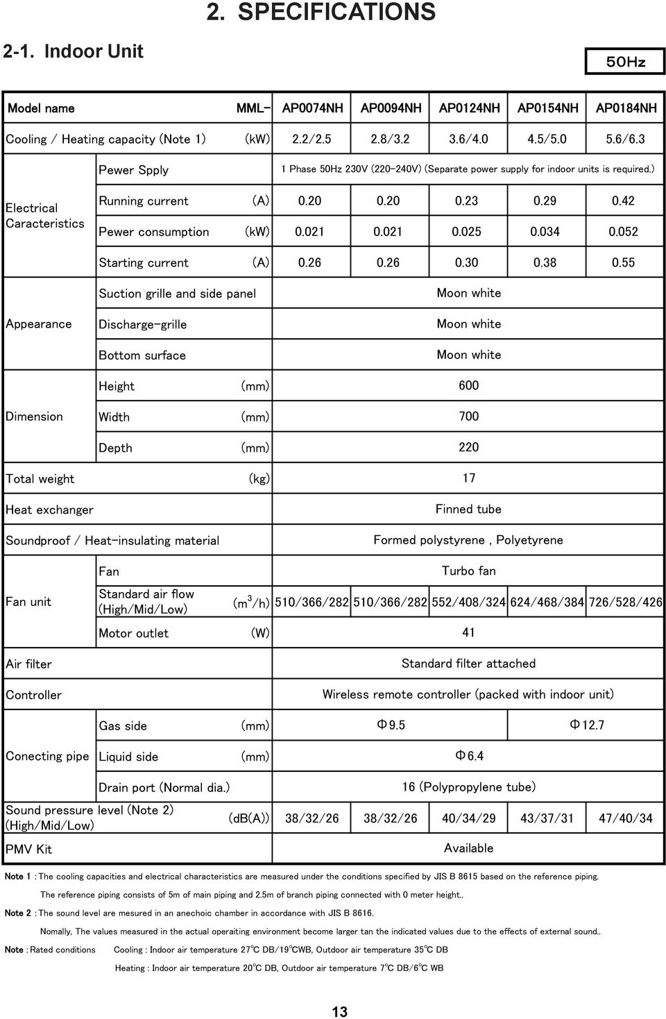
14 2. SPECIFICATIONS 2-. Indoor Unit 5 Hz Φ Φ Φ : : : 3
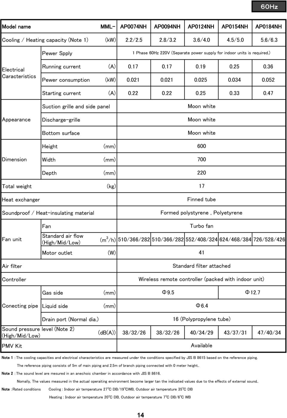
15 6 Hz Φ Φ Φ : : : 4
16 Indoor Unit 3. CONSTRUCTION VIEWS (EXTERNAL VIEWS) MML-AP0074NH-E, -TR MML-AP0094NH-E, -TR MML-AP024NH-E, -TR MML-AP054NH-E, -TR MML-AP084NH-E, -TR Dia. 80mm Connecting pipe MML- Liquid side Gas side AP0074 to AP024 type dia AP054 to AP084 type dia dia dia. 2.7 Back body Vertical louver (Upper air outlet) Front panel Air inlet grille Air filter Heat exchanger Air inlet Air inlet Air inlet Connecting pipe Gas side Connecting pipe Liquid side Dia. 80mm Knock out system Mounting screw Bottom air outlet Mounting screw Dia. 80mm Knock out system Mounting plate Dia. 80mm Space required for installation and servicing A C C Mounting screw Dia. 80mm Dia. 80mm Distance A 300 or more B 300 or more C 300 or more Front View 5 Drain hose Back side View

17 4. WIRING DIAGRAM Model: MML-AP0074NH-E, -TR, MML-AP0094NH-E, -TR, MML-AP024NH-E, -TR MML-AP054NH-E, -TR, MML-AP084NH-E, -TR TB0 L N HEAT EXCHANGER ~ 50Hz V 60Hz 220V RED WHI GRN & YEL CN67 (BLK) F30 T3. 5A 250V~ U FLOW SELECTOR UNIT (Sold separately) CN Broken lines indicate the wiring site. Long dashed short dashed line indicate the accessories. 2. indicates the terminal block. indicates the connection terminal. indicates the connector on the control P.C. board. 3. indicates the protection ground. 4. indicates the control P.C. board. BLK CN309 ( YEL ) CN8 ( BLK) CN23 ( WHI ) 7 Stepping motor PMV (Vertical air flow louver) M MS M 3~ 6 FM CN82 ( BLU) DISPLAY POWER SUPPLY CIRCUIT DC 20V DC 5V DC 2V DC 7V INFRARED RAYS RECEIVE AND INDICATION PARTS WP CN7 CN72 5 Stepping M motor (Damper) (CHK) (DISP) Control P.C. board for indoor unit (MCC-50) CN32 ( WHI ) FAN DRIVE CN20 ( WHI ) CN33 ( WHI ) CN50 ( WHI ) CN6 ( YEL ) CN60 ( WHI ) CN80 ( GRN) PNL CN44 ( BRW) CN40 ( BLU) CN4 ( BLU) CN00 ( BRW) CN0 ( BLU) CN02 ( YEL) CN04 ( WHI ) COLOR IDENTIFICATION RED : RED WHI : WHITE YEL : YELLOW BLU : BLUE BLK : BLACK GRY : GRAY PNK : PINK ORN : ORANGE BRW : BROWN GRN : GREEN GRN & YEL : GREEN & YELLOW TB02 BLU U BLU U2 BLK A BLK B t t t t OUTDOOR UNIT TC TC2 TCJ TA A U2 U B WIRED REMOTE CONTROLLER (Sold separately) 6

18 5. PARTS RATING 5-. Parts Rating No. Parts Name Type Specications Fan motor (for indoor) ICF Output (Rated) 4W, 340V DC 2 Louver motor MP24Z3T Output (Rated) W, 6 poles DC 3 Damper motor MP24Z3T Output (Rated) W, 6 poles DC 4 Thermo. Sensor (TA sensor) 268mm 0kΩ at 25 C 5 Heat exchanger sensor (TC sensor) Ø4.6mm 0kΩ at 25 C 6 Heat exchanger sensor (TC2 sensor) Ø6.8mm 0kΩ at 25 C 7 Heat exchanger sensor (TCJ sensor) Ø6.8mm 0kΩ at 25 C 8 PMV motor EFM-MD2TCTH- 2V DC 5-2. Name of Each Part Model : MML-APXXX4NH series Upper air outlet grille/louver Change the direction of the air to be discharged according to cool/heat mode. Air inlet grille Air in the room is sucked from here. Air filter Removes dirt or dust. (Provided in the air inlet grille) Lower air outlet grille/damper Earth screw Earth screws ore provided in the electric parts box. 7

19 5-3. Parts Name of Remote Controller n Display section In the display example, all indicators are displayed for the explanation. In reality only, the selected contents are indicated. When turning on the main power switch and leak breaker at the first time, SETTING flashes on the display part of the remote controller. While this display is flashing, the model is being automatically confirmed. Accordingly, wait for a while after SETTING display has disappeared, and then use the remote controller. FILTER RESET TEMP. TEST TIMER SET TIME SET CL FAN SAVE SWING/FIX ON / OFF MODE VENT UNIT LOUVER Display section Operation section This remote controller can control the operation of Max. 8 indoor units SETTING display Displayed during setup of the timer etc. 2 Operation mode select display The selected operation mode is displayed. 3 CHECK display Displayed while the protective device works or a trouble occurs. 4 Timer time display Time of the timer with H mark is displayed. (When a trouble occurs, the check code is displayed.) 5 Timer SET IN setup display When pushing the Timer SET IN button, the display of the timer is selected in order of [OFF] [OFF] repeat OFF timer [ON] No display. 6 Filter display If FILTER is displayed, clean the air filter. 7 TEST run display Displayed during a test run. 8 8 Louver position display (4-way Air Discharge Cassette, 2-way Air Discharge Cassette, -way Air Discharge Cassette, Under Ceiling, High Wall Type only (2H. 3H)) and Console Displays louver position. 9 SWING display Displayed during up/down movement of the louver. 0 Set up temperature display The selected set up temp. is displayed. Remote controller sensor display Displayed while the sensor of the remote controller is used. 2 PRE-HEAT display (Heat-pump model only) Displayed when the heating operation starts or defrost operation is carried out. While this indication is displayed, the indoor fan stops or the mode enters in LOW. 3 No function display Displayed if there is no function even if the button is pushed.

20 Air volume select display The selected air volume mode is displayed. (AUTO) (MED.) (HIGH) (LOW) 5 Louver Number display (exapmle:0, 02, 03, 04) 6 Operation ready display Displayed when cooling or heating operation is impossible because the outdoor temperature goes out of the operable range. 7 Mode select control display Displayed when pushing Operation mode select button while the operation mode is fixed to heating or cooling by the system manager of the air conditioner. 8 Louver lock display (4-way Air Discharge Cassette Type 2H series only) Displayed when there is a louver-locked unit in the group (including indoor unit by outdoor unit). 9 Unit Number display Unit number of the indoor unit selected with the unit select button or abnormal indication of the indoor/outdoor unit. 20 Central control display Displayed when the air conditioner is used under the central control in combination with a central control remote controller. In case the remote controller is disabled by the central control system, flashes. The button operation is not accepted. Even when you push ON/OFF, MODE, or TEMP. button, the button operation is not accepted. (Settings made by the remote controller vary with the central control mode. For details, refer to the Owner s Manual of the central control remote controller.) 9
 Displayed when there is a louver-locked unit in the group (including indoor unit by outdoor unit).")
21 n Operation section Push each button to select a desired operation. The details of the operation needs to be set up once, afterward, the air conditioner can be used by pushing ON / OFF button only. FAN button (Air volume select button) Selects the desired air volume mode. 2 TIMER SET button (Timer set button) TIMER SET button is used when the timer is set up. 3 TEST button (Check button) The CHECK button is used for the check operation. During normal operation, do not use this button. 4 VENT button (Ventilation button) Ventilation button is used when a fan which is sold on the market is connected. If No function is displayed on the remote VENT controller when pushing the Ventilation button, a fan is not connected. 5 FILTER RESET button (Filter reset button) Resets (Erases) FILTER display. 6 SAVE button (Power save operation) No function 7 SWING/FIX button (Swing/Wind direction button) Selects automatic swing or setting the louver direction. This function is not provided to Concealed Duct Standard Type, High Static Pressure Type, Floor Standing Cabinet Type, Floor Standing Concealed Type or Slim Duct Type. 8 Operation lamp Lamp is lit during the operation. Lamp is off when stopped. FILTER RESET TEMP. TEST Also it flashes when operating the protection device or abnormal time. TIMER SET SET TIME CL 8 20 FAN SAVE SWING/FIX ON / OFF 9 ON / OFF button When the button is pushed, the operation starts, and it stops by pushing the button again. When the operation has stopped, the operation lamp and all the displays disappear. 0 MODE button (Operation mode select button) Selects desired operation mode. UNIT LOUVER button (Unit/Louver select button) Selects a unit number (left) and louver number (right). UNIT: 2 TEMP. MODE VENT UNIT LOUVER Selects an indoor unit when adjusting wind direction when multiple indoor units are controlled with one remote controller. LOUVER (4-way Air Discharge Cassette Type 2H series only): Selects a louver when setting louver lock or wind direction adjustment independently. OPTION : button (Set up temperature button) Adjusts the room temperature. Set the desired set temperature by pushing TEMP. or TEMP.. Remote controller sensor Usually the TEMP. sensor of the indoor unit senses the temperature. The temperature on the surrounding of the remote controller can also be sensed. For details, contact the dealer from which you have purchased the air conditioner. In case that one remote controller controls the multiple indoor units, the setup operation is unavailable in group control.
22 5-4. Correct Usage When you use the air conditioner for the first time or when you change the SET DATA value, follow the procedure below. ON / OFF From the next time, the operation displayed on the remote controller will start by pushing the button only. n Preparation Turn on the main power switch and/or the leakage breaker. When the power supply is turned on, a partition line is displayed on the display part of the remote controller. After the power supply is turned on, the remote controller does not accept an operation for approx. minute, but it is not a failure. REQUIREMENT ON / OFF While using the air conditioner, operate it only with button without turning off the main power switch and the leak breaker. When you use the air conditioner after it has not been used for a long period, turn on the power switch at least 2 hours before starting operation. FAN 3 Select air volume with button. One push of the button, and the display changes in the order shown as follows. 4 TEMP. TIMER SET TIME FAN SAVE ON / OFF MODE VENT 3 2 AUTO HIGH MED. LOW FILTER RESET TEST SET CL SWING/FIX UNIT LOUVER Start Push ON / OFF button. The operation lamp goes on, and the operation starts. 2 Select an operation mode with the MODE MODE button. One push of the button, and the display changes in the order shown as follows. DRY mode function is not provided to Concealed Duct High Static Pressure Type. Cooling only model DRY COOL FAN Heat-pump model HEAT DRY COOL FAN (Dehumidify) When air volume is AUTO, air volume differs according to the room temperature. In DRY mode, AUTO is displayed and the air volume is LOW. In heating operation, if the room temperature is not heated sufficiently with VOLUME LOW operation, select MED. or HIGH operation. The temperature sensor senses temperature near the air inlet of the indoor unit, which differs from the room temperature depending on the installation condition. A value of setting temperature is the measure of room temperature. ( AUTO is not selectable in the FAN mode.) Air volume of function is not provided to Concealed Duct High Static Pressure Type but air speed HIGH only is displayed. 4 Determine the set up temperature by pushing the TEMP. or TEMP. button. AUTO Heat Recovery model HEAT DRY COOL FAN (Dehumidify) Stop Push ON / OFF button. The operation lamp goes off, and the operation stops. 2
23 [In case of cooling] Start the cooling operation after approx. minute. [In case of heating (For Heat-pump model only)] The heating operation mode is selected in accordance with the room temperature and operation starts after approximately 3 to 5 minutes. After the heating operation has stopped, FAN operation may continue for approx. 30 seconds. When the room temperature reaches the set temperature, the super low wind is discharged and the air volume decreases excessively. During defrost operation, the fan stops so that cool air is not discharged. ( NOTE When restarting the operation after stop PRE-HEAT is displayed.) When restarting the operation immediately after stop, the air conditioner does not operate for approx. 3 minutes to protect the machine. Automatic Operation (Super Heat Recovery Type Only) When you set the air conditioner in mode or switch over from AUTO operation because of some settings change, it will automatically select either cooling, heating, or fan only operation depending on the indoor temperature Adjustment of Wind Direction For best cooling and heating performance, adjust the louvers (adjustment of up/down wind direction) appropriately. CAUTION If cooling operation is performed with downward air outlet, dew may fall on surface of the cabinet or the horizontal louver resulted in dripping. If heating operation is performed with horizontal air outlet, unevenness of temperature may increase in the room. Do not move the horizontal louver directly with hands; otherwise a trouble is caused. Select direction of the horizontal louver using SWING/FIX switch on the remote controller. The horizontal louver does not stop immediately even if the switch is pushed. Adjusting the stop position, push the switch. 22
24 TIMER SET FAN MODE TIME SAVE VENT FILTER RESET TEST SET CL SWING/FIX UNIT LOUVER Unit select button n How to set up the wind direction Push SWING/FIX during operation. The wind direction changes for every push of the button. [In HEAT operation] Direct the louver (adjustment plate of up/down wind direction) downward. If directing horizontally, hot air may not come to the foot. n How to stop swinging Push SWING/FIX at a desired position while the louver is swinging. When SWING/FIX is pushed after that, wind direction can be set again from the highest position. However, even if SWING/FIX is pushed while the louver is swinging, the louver position is displayed as follows and highest position of the louver may not be selected. Display when swinging is stopped Initial setup [In COOL/DRY operation] Direct the louver (adjustment plate of up/down wind direction) horizontally. If directing it downward, the dew may form on the surface of the air discharge port and may drop down. Initial setup FAN/HEAT operation COOL/DRY operation In this case, push SWING/FIX again two seconds later. In COOL/DRY operation, the louver does not stop as it directs downward. If stopping the louver as it directs downward during swing operation, it stops after moving to the third position from the highest position. Display when stopping the swing [In FAN operation] Select a desired wind direction. FAN/HEAT operation COOL/DRY operation n How to start swinging Push SWING/FIX, set the louver (adjustment plate of up/down wind direction) direction to the lowest position, and then push SWING/FIX again. SWING is displayed and the up/down wind direction is automatically selected. Display during swinging Repeat Initial setup 23 Unit select button When multiple indoor units are controlled with one remote controller, wind direction can be set for each indoor unit by selecting individually. UNIT LOUVER To set wind direction individually, push button to display an indoor unit number in the control group. Then set the wind direction of the displayed indoor unit. When no indoor unit number is displayed, all indoor units in the control group can be controlled simultaneously. Each time you push UNIT LOUVER button, the display changes as follows: Unit No. - Unit No. -2 Unit No. -3 No display Unit No. -4
25 Adjusting airflow direction Adjust the airfl ow direction properly. Otherwise, it might cause discomfort and make the room temperature uneven. Adjust the vertical airfl ow using the remote controller. Adjust the horizontal airfl ow manually. To automatically swing the airflow direction Perform this function when the air conditioner is in operation. Adjust the vertical airflow The air conditioner automatically adjusts the vertical airfl ow direction in accordance with the operating conditions when AUTO or A mode is selected. To set the airflow direction you desire Perform this function when the air conditioner is in operation. CAUTION NOTE Operating angle of vertical airfl ow louver will be different during cooling, dry and heating operation. Concerning airfl ow from the lower air outlet grille. In the cooling operation, airfl ow is blown out only from the upper air outlet grille under some operating conditions. In the dry operation, airfl ow is blown out only from the upper air outlet grille. The FIX and SWING buttons will be disabled when the air conditioner is not in operation (including when the ON timer is set). Do not operate the air conditioner for long hours with the airfl ow direction set downward during the cooling or dry operation. Otherwise, condensation may occur on the surface of the vertical airfl ow louver and cause dew dripping. Do not move the vertical airfl ow louver manually. Always use the FIX button. If you move the louver manually, it may malfunction during operation. If the louver malfunctions, stop the air conditioner once, and restart. When the air conditioner is started immediately after it was stopped, the vertical airfl ow louver might not move for 0 seconds or so. Louver operation is limited when performing group control. (see page 2) Air ow from the lower air outlet grille (Damper control) Damper is moved (to OPEN or to CLOSED automatically. In the COOLING operation, Damper is determined according to room temparature and running time. In the DRY operation, damper is closed. In the HEATING operation, damper is open. Operation COOLING DRY HEATING Running time less than H more than H - - Room temparature Ta Tsc+2 Ta<Tsc Bi Flow Upper Flow Upper Flow Upper Flow Bi Flow When is selected) Lower Flow Airflow air w Da Damper OPEN CLOSED CLOSED CLOSED OPEN When [Hi POWER] is selected with wireless remote controller,running time is cleared once. 24
26 Adjust the horizontal airflow Preparation Take hold of the lever on the horizontal airfl ow louver and move them to adjust the airfl ow direction as required. You can adjust the airfl ow at the left, and right locations of the louver. 25
27 5-6. Timer Operation A type of timer operation can be selected from the following three types. (Setting of up to 68 hours is enabled.) OFF timer : The operation stops when the time of timer has reached the set time. Repeat OFF timer : Every time, the operation stops after the set time has passed. ON timer : The operation starts when the time of timer has reached the set time. n Timer operation 3 FILTER RESET TEST TIMER SET TIME SET CL FAN SAVE SWING/FIX MODE VENT UNIT LOUVER 2 4 Set Push TIMER SET button. The timer display (type) changes for every push of the button. Example of remote controller display In the case of 23.5 hours ( ) OFF OFF ON In the case of 34 hours ( 2) (OFF timer) (Repeat OFF timer) (ON timer) No display SETTING and timer time displays flash. TIME 2 Push to select SET TIME. For every push of button, the set time increases in the unit of 0.5 hr (30 minutes). When setting a time more than 24 hours for timer operation, timer time can be set in the unit of hr. The maximum set time is 68hr (7 days). The remote controller displays the set time with time (between 0.5 and 23.5 hours) ( ) or number of days and time (24 hours or more) ( 2) as shown below. For every push of button, the set time decreases in the unit of 0.5 hr (30 minutes) (0.5 to 23.5 hours) or hr (24 to 68 hours). Number of days Time shows day (24 hours). shows 0 hours. (Total 34 hours). 3 Push SET button. SETTING display disappears and timer time display goes on, and or display flashes. (When ON timer is activated, timer time, ON timer are displayed and other displays disappear.) 4 Cancel of timer operation Push CL button. TIMER display disappears. NOTE When the operation stops after the timer reached the preset time, the Repeat OFF timer resumes the ON / OFF operation by pushing button and stops the operation after the reached the set time. When you push SWING/FIX while the OFF timer function of the air conditioner is active, the indication of the timer function disappears and then appears again after about 5 seconds. This is due to normal processing of the remote controller. 26
28 5-7. Installation Installation place CAUTION Check that the air conditioner is not installed in a place subject to combustible gas leak. Accumulation of combustible gas around the unit may cause a fire. Drain the dehumidified water from the indoor unit and outdoor unit to a well-drained place. Do not put any obstacle near the air inlets and air outlet of the outdoor unit. Doing so may hinder the radiation, which may reduce the performance or activate the protective device. Electrical wiring WARNING Be sure to connect earth wire. (grounding work) Incomplete grounding cause an electric shock. Do not connect ground wires to gas pipes, water pipes, lightning rods or ground wires for telephone wires. CAUTION Make sure that a leakage breaker is connected. Using the air conditioner without leakage breaker may cause electric shock. Use a leakage breaker with an appropriate capacity. Be sure to use the rated voltage and an exclusive circuit for power supply of the air conditioner. Do not install the air conditioner in the following places Do not install the air conditioner in any place within m from a TV, stereo, or radio set. If the unit is installed in such place, noise transmitted from the air conditioner affects the operation of these appliances. Do not install the air conditioner near a high frequency appliance (sewing machine or massager for business use, etc.), otherwise the air conditioner may malfunction. Do not install the air conditioner in a humid or oily place, or in a place where steam, soot, or corrosive gas is generated. Do not install the air conditioner in a salty place such as seaside area. Do not install the air conditioner in a place where a great deal of machine oil is used. Do not install the air conditioner in a place where it is usually exposed to strong wind such as in seaside area. Do not install the air conditioner in a place where sulfureous gas generated such as in a spa. Do not install the air conditioner in a vessel or mobile crane. Do not install the air conditioner in an acidic or alkaline atmosphere (in a hot-spring area or near a chemicals factory, or in a place subject to combustion emissions). Corrosion may be generated on the aluminum fin and copper pipe of the heat exchanger. Do not install the air conditioner near an obstacle (air vent, lighting equipment, etc.) that disturbs discharge air. (Turbulent airflow may reduce the performance or disable devices.) Do not use the air conditioner for special purposes such as preserving food, precision instruments, or art objects, or where breeding animals or growing plants are kept. (This may degrade the quality of preserved materials.) Do not install the air conditioner over an object that must not get wet. (Condensation may drop from the indoor unit at a humidity of 80% or more or when the drain port is clogged.) Do not install the air conditioner in a place where an organic solvent is used. Do not install the air conditioner near a door or window subject to humid outside air. Condensation may form on the air conditioner. Do not install the air conditioner in a place where special spray is used frequently. Be careful with noise or vibrations Do not install the air conditioner in a place where noise by outdoor unit or hot air from its air outlet annoys your neighbors. Install the air conditioner on a solid and stable foundation so that it prevents transmission of resonating, operation noise and vibration. If one indoor unit is operating, some sound may be audible from other indoor units that are not operating. 27
29 5-8. Maintenance WARNING Be sure to turn off the main power switch prior to the maintenance. Please do not intend to do the daily maintenance and/or Air Filter cleaning by yourself. Cleaning of the air filter and other parts of the air filter involves dangerous work in high places, so be sure to have a service person do it. Do not attempt it yourself. Cleaning of air filters Clogging of air filters will reduce the cooling and heating performance. When FILTER appears on the remote controller, clean the air filters. 2 When the cleaning of air filters has been completed, RESET button. FILTER disappears. push FILTER TEMP. ON / OFF TIMER SET FAN MODE 2 FILTER RESET TEST SET TIME CL SAVE SWING/FIX VENT UNIT LOUVER CAUTION Cleaning of unit Clean the unit with a soft dry cloth. If dirt cannot be removed with the dry cloth, use a cloth slightly dampened with lukewarm (under 40 C) water. Cleaning of remote controller Use a dry cloth to wipe the remote controller. A cloth dampened with cold water may be used on the indoor unit if it is very dirty. Never use a damp cloth on the remote controller. Do not use a chemically-treated duster for wiping or leave such materials on the unit for long. It may damage or fade the surface of the unit. Do not use benzine, thinner, polishing powder, or similar solvents for cleaning. These may cause the plastic surface to crack or deform. Thinner Periodic check Long-period use of the air conditioner may cause deterioration or failure of parts due to heat, humidity, dust, and operating conditions, or may cause poor drainage of dehumidified water. If you do not plan to use the unit for more than month ) Operate the fan for 3 to 4 hours to dry inside the unit. Operate FAN mode. 2) Stop the air conditioner and turn off the main power switch or the circuit breaker. Checks before operation ) Check that the air filters are installed. 2) Check that the air outlet or inlet is not blocked. 3) Turn on the main power switch or the circuit breaker for the main power supply to the air conditioner. 28
30 NOTE For environmental conservation, it is strongly recommended that the indoor and outdoor units of the air conditioner in use be cleaned and maintained regularly to ensure efficient operation of the air conditioner. When the air conditioner is operated for a long time, periodic maintenance (once a year) is recommended. Furthermore, regularly check the outdoor unit for rust and scratches, and remove them or apply rustproof treatment, if necessary. As a general rule, when an indoor unit is operated for 8 hours or more daily, clean the indoor unit and outdoor unit at least once every 3 months. Ask a professional for this cleaning/maintenance work. Such maintenance can extend the life of the product though it involves the owner s expense. Failure to clean the indoor and outdoor units regularly will result in poor performance, freezing, water leakage, and even compressor failure. Maintenance List Part Heat exchanger Fan motor Check (visual/auditory) Dust/dirt clogging, scratches Sound Maintenance Wash the heat exchanger when it is clogged. Take appropriate measures when abnormal sound is generated. Filter Fan Air inlet/outlet grilles Drain pan Ornamental panel, louvers Dust/dirt, breakage Vibration, balance Dust/dirt, appearance Dust/dirt, scratches Dust/dirt clogging, drain contamination Dust/dirt, scratches Wash the filter with water when it is contaminated. Replace it when it is damaged. Replace the fan when vibration or balance is terrible. Brush or wash the fan when it is contaminated. Fix or replace them when they are deformed or damaged. Clean the drain pan and check the downward slope for smooth drainage. Wash them when they are contaminated or apply repair coating. Re-Installation WARNING Ask the dealer or an installation professional to re-install the air conditioner to a new place or move it to another place and to observe the following items. If the air conditioner is inappropriately installed by yourself, it may cause electric shock or fire. CAUTION Be sure to clean the heat exchanger with pressurized water. If an commercially detergent (strong alkaline or acid cleaning agent) is used, the surface treatment of the heat exchanger will be marred, which may degrade the self cleaning performance. For details, contact the dealer. 29
31 Cleaning the air filter Clean the air fi lters every 2 weeks. If the air fi lters are covered with dust, the performance of the air conditioner will deteriorate. Cleaning the air inlet grille. Remove the air inlet grille by release the rope from the hook. Clean the air fi lters as often as possible.. Open the air inlet grille by gripe at the handle then pull the air inlet grille as the arrow direction. 2. Take hold the left and right handles of air fi lter and push it down to release them from holding slot, then pull it upward to take it out. 2. Wash it with water using a soft sponge or towel. (Do not use metallic scrubbing brush or the other hard brushed) Use of such hard objects will cause scratches on the surface of air inlet grille. If very dirty, clean the air inlet grille with a neutral detergent for kitchen use, and rinse it off with water. Filter holder 3. Wipe out water from air inlet grille and dry it. 3. Use a vacuum cleaner to remove the dust from the fi lter or wash them with water. If you wash the air fi lter, dry them in the shade. 4. Insert the lower hooks of air inlet grille into the slots. Lower hooks 4. Insert the lower ribs of air fi lter into the slots then set it into the holding slot. (reverse the procedure number 2) 5. Hang the rope at the back side hook then close the air inlet grille. Lower ribs 5. Close the air inlet grille. 30
32 5-9. Air Conditioner Operations and Performance Check before operation Check whether earth wire is disconnected or out of place. Check that air filter is installed to the indoor unit. Check that the air outlet or inlet is not blocked. Turn on the main power switch or the circuit breaker for the main power supply to the air conditioner. Heating capacity (for Heat-pump model only) For heating, a heat pump system which sucks in outside heat air and discharges it into the room is adopted. If temperature of the outside air lowers, the heating capacity decreases. When temperature of the outside air is low, it is recommended to use other heating equipment together. Defrost operation during heating operation (for Heat-pump model only) If the outdoor unit has some frost during heating operation, the operation mode changes automatically to defrost mode to increase the heating effect (for approx. 2 to 0 minutes). During defrost operation, fans of the indoor and the outdoor units stop. 3 minutes protection The outdoor unit does not operate for approx. 3 minutes after air conditioner has been immediately restarted after stop, or power switch has been turned on. This is to protect the system. Main power failure If a power failure occurred during the operation, all operations stop. When restarting the operation, push ON/OFF button again. Fan rotation of stopped unit While other indoor units operate, the fan on indoor units on stand-by rotates to protect the machine once per approx. hour for several minutes. Protective device (High pressure switch) The high pressure switch stops the air conditioner automatically when excessive load is applied to the air conditioner. If the protective device works, the operation lamp keeps lit but the operation stops. When the protective device works, in the remote controller display part flash. The protective device may work in the following cases. <Cooling operation> When the air inlet or air outlet of the outdoor unit is blocked. When strong wind blows continuously against the air outlet of the outdoor unit. <Heating operation> When dust or dirt is excessively adhered to air filter of the indoor unit. When the air outlet of the indoor unit is blocked. Cooling/heating operation of Modular Multi system air conditioner In Modular Multi system air conditioner, each indoor unit can be individually controlled. However, cooling operation and heating operation cannot be performed concurrently for the indoor units which are connected to one outdoor unit. When cooling operation and heating operation are performed concurrently, the indoor unit which is performing cooling operation stops, and on the display is lit. The indoor unit which is performing heating operation continues operation. If the manager has fixed the setting to COOL or HEAT, other operation than set up one cannot be performed. When other operation than set up one is performed, on the display is lit and the operation stops. Characteristics of heating operation (for Heat-pump model only) Hot air is not out immediately after the operation has started. After 3 to 5 minutes (differs according to room or outside temperature) has passed and the indoor heat exchanger has been warmed up, hot air blows out. During operation, the outdoor unit may stop if outside temperature becomes high. When other outdoor unit performs heating operation while the fan is operating, the fan operation may be stopped temporarily to prevent blowing of hot air. Air conditioner operating conditions For proper performance, operate the air conditioner under the following temperature conditions: Cooling operation Heating operation If air conditioner is used outside of the above conditions, safety protection may operate. WARNING Turn on the power switch 2 hours or more before starting before operation. Outdoor temperature : 5 C to 43 C (Dry-bulb temp.) Room temperature : 2 C to 32 C (Dry-bulb temp.), 5 C to 24 C (Wet-bulb temp.) CAUTION Room relative humidity: less than 80 %. If the air conditioner operates in excess of this figure, the surface of the air conditioner may cause dewing. Outdoor temperature : 5 C to 5.5 C (Wet-bulb temp.) Room temperature : 5 C to 28 C (Dry-bulb temp.) 3
33 5-0. When the Following Symptoms are Found Check the points described below before asking repair servicing. Outdoor unit Symptom White misty cold air or water is out. Sometimes, noise Pushu! is heard. Cause Fan of the outdoor unit stops automatically and performs defrost operation. Solenoid valve works when defrost operation starts or finishes. It is not a failure. Indoor unit Swish sound is heard sometimes. Slight Pishi! sound is heard. Discharge air smells. indication is lit. Sound or cool air is output from the stand by indoor unit. When power of the air conditioner is turned on, Ticktock sound is heard. Fan and louvers of the indoor unit moves when the unit is not operated. When the operation has started, during the operation, or immediately after the operation has stopped, a sound such as water flows may be heard, and the operation sound may become larger for 2 or 3 minutes immediately after the operation has started. They are flowing sound of refrigerant or draining sound of dehumidifier. This is sound generated when heat exchanger, etc. expand and contract slightly due to change of temperature. Various smell such as one of wall, carpet, clothes, cigarette, or cosmetics adhere to the air conditioner. When cooling operation cannot be performed because another indoor unit performs heating operation. When the manager of the air conditioner has fixed the operation to COOL or HEAT, and an operation contrary to the setup operation is performed. When fan operation stopped to prevent discharge of hot air. Since refrigerant is flowed temporarily to prevent stay of oil or refrigerant in the stand by indoor unit, sound of flowing refrigerant, Kyururu or Shaa may be heard or white steam when other indoor unit operates in HEAT mode, and cold air in COOL mode may be blow-out. Sound is generated when the expansion valve operates when power has been turned on. Intermittent operation of the fan with louvers open is sometimes carried out for the refrigerant recovery control of unoperated unit. Operates or stops automatically. Is the timer ON or OFF? Check again. Does not operate. Air is not cooled or warmed sufficiently. It s strange. Is it a power failure? Is the power switch turned off? Is the power fuse or breaker blown? Has the protective device operated? (The operation lamp goes on.) Is the timer ON? (The operation lamp goes on.) Are COOL and HEAT selected simultaneously? ( indication is lit on the display of the remote controller.) Is the air inlet or air outlet of the outdoor unit obstructed? Are any door or window open? Is the air filter clogged with dust? Is discharge louver of the indoor unit set at appropriate position? Is air selection set to LOW MED, and is the operation mode set to FAN? Is the setup temp. the appropriate temperature? Are COOL and HEAT selected simultaneously? ( indication is lit on the display of the remote controller.) CAUTION If any of the following conditions occur, turn off the main power supply switch and immediately contact the dealer : Switch operation does not work properly. The main power fuse often blows out, or the circuit breaker is often activated. A foreign matter or water fall inside the air conditioner. When the air conditioner does not operate even after the cause of the protective device activation has been removed. (The operation lamp and on the remote controller are flashing.) Any other unusual conditions are observed. 32
34 Confirmation and check When a trouble occurred in the air conditioner, the check code and the indoor unit No. appear on the display part of the remote controller. The check code is only displayed during the operation. If the display disappears, operate the air conditioner according to the following Confirmation of error history for confirmation. Check code Indoor unit No. in which an error occurred Confirmation of error history When a trouble occurred on the air conditioner, the trouble history can be confirmed with the following procedure. (The trouble history is stored in memory up to 4 troubles.) The history can be confirmed from both operating status and stop status. 2 3 TEMP. FILTER RESET TEST TIMER SET TIME SET CL FAN SAVE SWING/FIX ON / OFF MODE VENT UNIT LOUVER Procedure 2 3 Description When pushing SET and TEST buttons at the same time for 4 seconds or more, the following display appears. If [ Service check] is displayed, the mode enters in the trouble history mode. [0 : Order of trouble history] is displayed in CODE No. window. [Check code] is displayed. [Indoor unit address in which an error occurred] is displayed in UNIT No. Every pushing of [ / ] button used to set temperature, the trouble history stored in memory is displayed in order. The numbers in CODE No. indicate CODE No. [0] (latest) [04] (oldest). CAUTION Do not push CL button because all the trouble history of the indoor unit will be deleted. After confirmation, push TEST button to return to the usual display.. Check the troubles according to the above procedure. 2. Ask an authorized dealer or qualified service (maintenance) professional to repair or maintain the air conditioner. 3. More details of the service code are explained in Service Manual. Check these items. If any of these problems still remains, stop the operation, turn off the leakage breaker, and then notifies the dealer of the serial number and details of the error. Never repair any part by yourself as it is dangerous. When and a combination of,,,, or and a number are displayed on the remote controller, also inform the dealer of the display content. 33
35 6. REFRIGERATING CYCLE DIAGRAM Liquid side Gas side Strainer Capillary tube Air heat exchanger at indoor side Pulse Motor Valve (PMV) Sensor (TC2) Distributor Sensor (TCJ) Fan Sensor (TC) Sensor (TA) M Fan motor Functional part name Pulse Motor Valve PMV Functional outline (Connector CN082 (6P): Blue) ) Controls super heat in cooling operation 2) Controls under cool in heating operation 3) Recovers refrigerant oil in cooling operation 4) Recovers refrigerant oil in heating operation Temp. sensor. TA 2. TC 3. TC2 4. TCJ (Connector CN04 (2P): White) ) Detects indoor suction temperature (Connector CN00 (3P): Brown) ) Controls PMV super heat in cooling operation (Connector CN0 (2P): Blue) ) Controls PMV under cool in heating operation (Connector CN02 (2P): Yellow) ) Controls PMV super heat in cooling operation 34
36 7-. Control Specifications 7. CONTROL OUTLINE No. Item Outline of specifications Remarks When power supply is reset ) Distinction of outdoor unit When the power supply is reset, the outdoors are distinguished and the control is selected according to the distinguished result. 2) If resetting the power supply during occurrence of a trouble, the check code is once cleared. After ON/OFF button of the remote controller was pushed and the operation was resumed, if the abnormal status continues, the check code is again displayed on the remote controller. 2 Operation mode selection ) Based on the operation mode selecting command from the remote controller, the operation mode is selected. Remote controller command STOP FAN COOL DRY HEAT AUTO (SHRM only) Control outline Air conditioner stops. Fan operation Cooling operation Dry operation Heating operation Ta and Ts automatically select COOL/ HEAT operation mode for operation. Ta: Room temp. Ts: Setup temp. Except SHRM, the automatic mode cannot be selected. While a wireless remote controller is used, the mode is notified by Pi Pi (two times) receiving sound. To clear the alternate flashing, change the mode on the wireless remote controller. 3 Room temp. control ) Adjustment range: Remote controller setup temperature ( C) COOL/DRY HEAT AUTO For SHRM only Wired type 8 to 29 8 to 29 8 to 29 Wireless type 7 to 30 7 to 30 7 to 30 2) Using the Item code 06, the setup temperature in heating operation can be corrected. Setup data Shift of suction temperature in heating operation Setup temp. correction Setting at shipment Setup data 3 +0 C +2 C +3 C +4 C +6 C Except while sensor of the remote controller is controlled (Code No. [32], 000 ) 4 Automatic capacity control ) Based on the difference between Ta and Ts, the operation capacity is determined by the outdoor unit. Ts: Setup temp. Ta: Room temp. 35
37 No. Item Outline of specifications Remarks 5 Air speed selection ) Operation with (HH), (H), (L) or [AUTO] mode is carried out by the command from the remote controller. For the wireless remote controller type, (HH), (H+), (H), (L+), (L) or [AUTO] operation is carried out. 2) When the air speed mode [AUTO] is selected, the air speed varies by the difference between Ta and Ts. HH > H+ > H > L+ > L > UL 6 Prevention of cold air discharge. In heating operation, the higher temperature of TC2 sensor and TCJ sensor is compared with temperature of TC sensor and then the lower temperature is used to set the upper limit of the fan tap. When B zone has continued for 6 minutes, the operation shifts to C zone. In defrost time, the control point is set to +6 C. ( C) D C E B A TCJ: Temperature of indoor heat exchanger sensor In D and E zones, priority is given to remote controller air speed setup. In A zone is displayed. A zone: OFF B zone: Over 26 C, below 28 C, ULTRA LOW (LL) C zone: Over 28 C, below 30 C, LOW (L) D zone: Over 30 C, below 32 C, MED (H) E zone: HIGH (HH) 7 Freeze prevention control (Low temp. release). In all cooling operation, the air conditioner operates as described below based upon temp. detected by TC, TC2 and TCJ sensors. ( C) P Q ( C) P2 Q2 J I L N M K a 2. In all cooling operation, the air conditioner operates as described below based upon temp. detected by TC2 and TCJ sensors. When M zone is detected for 45 minutes, the thermostat is forcedly off. In N zone, the timer count is interrupted and held. When shifting to M zone again, the timer count restarts and continues. If L zone is detected, the timer is cleared and the operation returns to normal operation. Reset conditions ) TC > 2 C and TC2 > 2 C and TCJ > 2 C 2) 20 minutes passed after stop. TC: Temperature of indoor heat exchanger sensor When J zone is detected for 5 minutes, the thermostat is forcedly off. In K zone, the timer count is interrupted, and held. When I zone is detected, the timer is cleared and the operation returns to the normal operation. If forced thermo OFF by continuation of J zone, operation of the indoor fan in LOW mode continues until it reaches the I zone. It is rest when the following conditions are satisfied. Reset conditions ) TC > 2 C and TC2 > 2 C and TCJ > 2 C 2) 20 minutes passed after stop. P Q P2 Q2 TC 0 C (5 C) 0 C TC2, TCJ TC2, TCJ 5 C 2.0 C 0 C 4 C ( ) value: When the power supply is turned on, the Forced thermo becomes OFF if the temperature is less than this indicated temperature. 36
38 No. Item Outline of specifications Remarks 8 Recovery control for cooling oil (Refrigerant) The indoor unit which is under STOP/Thermo-OFF status or which operates in [FAN] mode performs the following controls when it received the cooling oil (Refrigerant) recovery signal from the outdoor unit. ) Opens PMV of the indoor unit with a constant opening degree. 2) Stop the indoor fan. Recovery operation is usually performed every 2 hours. 9 Recovery control for heating refrigerant (Oil) The indoor unit which is under STOP/Thermo-OFF status or which operates in [FAN] mode performs the following controls when it received the heating refrigerant (Oil) recovery signal from the outdoor unit. ) Opens PMV of the indoor unit with a constant opening degree. 2) Stop the indoor fan. The indoor unit which is under thermo-off (COOL) status or which operates in [FAN] mode stops the indoor fan and displays [ ]. Recovery operation is usually performed every hour. 0 Compensation control for short intermittent operation ) For 3 minutes after start of operation, the operation is forcedly continued even if the unit enters in Thermo-OFF condition. 2) Howev er the thermostat is OFF giv ing prior to COOL/HEAT selection, ready for operation and protective control. Usually the priority is given to 5 minutes at outdoor controller side. Elimination of retained heat ) When the unit stopped from [HEAT] operation, the indoor fan operates with [L] for approx. 30 seconds. 2 HA control ) ON/OFF operation is available by input of HA signal from the remote site when connected to remote controller or the remote ON/OFF interface. 2) HA control outputs ON/OFF status to HA terminal. 3) The I/O specifications of HA conform to JEMA standard. When using HA terminal (CN6) for the remote ON/ OFF, a connector sold separately is necessary. In case of group operation, use the connector to connect HA terminal to either master or follower indoor unit. 3 Display of filter sign [ ] (Not provided to the wireless type) Separately set type TCB-AX2E2 is prepared. ) The filter sign is displayed with LC by sending the filter-reset signal to the remote controller when the specified time (5 0H) elapsed as a result of integration of the operation time of the indoor fan. 2) The integrated timer is cleared when the filter-reset signal is received from the remote controller. In this time, if the specified time elapsed, the counted time is reset and the LC display is deleted. [ FILTER] goes on. 37
39 No. Item Outline of specifications Remarks 4 Display of [ OPERATION READY] [ PRE-HEAT] <OPERATION READY> Displayed on the remote controller ) When the following check codes are indicated Open phase of power supply wiring [P05] was detected. There is an indoor unit that detected the indoor overflow [P0]. There is an indoor unit that detected the interlock alarm [L30]. 2) During Force Thermo-OFF [COOL/DRY] operation is unavailable because the other indoor unit operates with [HEAT] mode. [HEAT] operation is unavailable because COOL priority (SW-bit of the Outdoor P. C. board is ON) is set and the other indoor unit operates with [COOL/DRY] mode. 3) The above indoor units that cannot operate stay in Thermo-OFF status. 4) The indoor fan stops because the system performs [Recovery operation for heating refrigerant (Oil)]. < > display No display for wireless remote controller <PRE-HEAT> Displayed on the remote controller The indoor fan stops in order to prevent discharge of cool air when heating operation started or during heating operation. (including the defrost operation during thermo-off) < > display 5 Selection of central control mode ) Selection of the contents that can be operated by the remote controller at the indoor unit side is possible according to setting at the central controller side. 2) Setting contents In case of TCC-LINK central control Operation from TCC-LINK central control Individual [Central ] [Central 2] [Central 3] [Central 4] Operation on RBC-AMT32E ON/OFF Operation Timer Temp. Air speed Air direction setting selection setting setting setting setting On RBC-AMT32E No display [Central control ] display ( : Operation possible : Operation impossible) In case of wired remote controller type, [Central control ] display (Goes on) in the central control mode Display flashes when an item of the operation prohibited was changed on the remote controller. In case of wireless remote controller type, the display lamp does not change but the contents that can be operated are same in the central control mode. ( ) The operation from the wireless remote controller in the central control mode is notified with the receiving sound, Pi, Pi, Pi, Pi, Pi (5 times). ( ) If the operation select modes are different in the central 2 to 4 from those at the central controller side, the operations Temp. Setting, air volume setting, and air direction setting are inoperable. 38
40 No. Item Outline of specifications Remarks 6 Louver control ) Louver position setup (Wired type) The louver position can be set up in the following operation range. In cooling/dry operation In heating/fan operation In group operation, the louver positions can be set up collectively or individually. 2) Swing setup The following display is repeated. In all operations (Repeats) In group operation, the louver positions can be set up collectively or individually. 3) FIX setup (Wireless type) Keep pushing or pushing briefly the FIX button to move the louver in the desired direction. Operating angle of louver will be different during cooling, dry and heating operation. 4) When the unit stopped or the warning was output, the louver is automatically set to full closed position. 5) When PRE-HEAT is displayed (Heating operation started or defrost operation is performed), heating thermo is off, the louver is automatically set to closed. 7 Hi POWER operation (Wireless remote controller specific operations) When you push the Hi POWER button during cooling, heating or A operation, the air conditioner will start the following operation. Cooling operation Performs the cooling operation at C lower than the setting temperature. Only when the fan speed before the Hi POWER operation is not high, the fan speed will be increased. [Hi POWER] Display When the Hi POWER is selected, running time for the damper control is cleared once. Heating operation Performs the heating operation at 2 C higher than the setting temperature. Only when the fan speed before the Hi POWER operation is not high, the fan speed will be increased. 39
41 No. Item Outline of specifications Remarks 8 COMFORT SLEEP operation (Wireless remote controller specific operations) When you push the COMFORT SLEEP button during cooling, heating or A operation, the air conditioner will start the following operation. The fan speed display will indicate AUTO and low speed will be used. Cooling operation In the operation suppression zone, where capacity is kept to the minimum, overcooling is prevented by raising the temperature setting by C after hour and by 2 C after 2 hours of operation. The room temperature is thus regulated between the operation suppression zone and the set temperature. When the OFF timer is simultaneously set,, 3, 5 and 9 hours appear by turns every pushing COMFORT SLEEP button and one of them can be selected for OFF timer. [ ] display Heating operation In the operation suppression zone, where capacity is kept to the minimum, overheating is prevented by lowering the temperature setting by C after hour and by 2 C after 2 hours of operation. The room temperature is thus regulated between the set temperature and the operation suppression zone. When the OFF timer is simultaneously set,, 3, 5 and 9 hours appear by turns every pushing COMFORT SLEEP button and one of them can be selected for OFF timer. Operation suppression zone Set temperature Operation starts C hour 2 hours 2 C Set temperature Operation starts C hour 2 hours 2 C Operation suppression zone 9 PRESET operation (Wireless remote controller specific operations) Start the air conditioner in the operation mode which you want the remote controller to memorize. ) Push and hold the PRESET button for more than 3 seconds while the display flashes. The mark is indicated and the setting is memorized. If you do not push the PRESET button within 3 seconds or if you push another button, the memory setting is cancelled. Operation modes which can be memorized with the PRESET button are MODE, Temperatures, FAN, TIMER and Hi POWER. [ ] display To operate the air conditioner with the setting memorized by the PRESET button. ) Push the PRESET button briefly. The setting memorized will be indicated and the air conditioner operates with regards to the setting. The lamp (green) on the display panel of the indoor unit goes on, and operation starts after approximately 3 minutes. Initial setting: MODE : AUTO Temperature : 22 40
42 No. Item Outline of specifications Remarks 20 QUIET operation (Wireless remote controller specific operation) When you push the QUIET button during cooling, heating, fan only or A operation, the air conditioner will start the following operation. The fan speed display will indicate AUTO and low speed will be used. [ ] display 2 SLEEP operation (Wireless remote controller specific operation) When the OFF timer is set,, 3, 5 and 9 hours appear by turns every pushing SLEEP button and one of them can be selected for OFF timer. 22 Save operation ) The function [Save operation] is not provided to the Super Modular Multi series models. If pushing [SAVE] button on the remote controller, No function is displayed. 4
43 8. CONFIGURATION OF CONTROL CIRCUIT 8-. Indoor Controller Block Diagram 8--. Case of Main (Sub) Remote Controller Connected Main (Sub) master remote controller (Up to 2 sets) Display part LCD Display part LED CPU Remote controller communication circuit Function setup Key switch DC5V Power circuit CN2 CN * 2 Weekly timer LCD driver CPU DC5V Power circuit Display part LCD Function setup Key switch Secondary battery Indoor unit # A B A B A B Main P.C. board (MCC-50) DC20V Remote controller communication circuit Central control remote controller (Option) * U3 U4 Sensor display P.C. board (MCC-5044) Sensor part LED Central control communication circuit DC5V Driver Driver CPU EEPROM TA sensor TC sensor TCJ sensor Same as left Same as left HA Damper motor Louver motor Outside output Start/Alarm/Ready Thermostat ON COOL/HEAT/FAN DC2V Fan motor control circuit Remote controller A/B setup BUS Communication circuit L N UU2 L N UU2 Indoor fan motor DC280V Power circuit AC synchronous signal input circuit Power supply Power supply L N U U2 Outdoor unit Outdoor unit Max. 8 units are connectable. * In group connection, mount the central control remote controller to group header unit. *2 Connection of weekly timer to sub remote controller is unavailable. L N Power supply Ø V, 50Hz Ø 220V, 60Hz U2 U Outdoor unit 42
44 8--2. Case of Wireless Remote Controller Kit Connected Indoor unit # A B A B A B Main P.C. board (MCC-50) DC20V Remote controller communication circuit Central control remote controller (Option) * U3 U4 Sensor display P.C. board (MCC-5044) Sensor part LED Central control communication circuit DC5V Driver Driver CPU EEPROM TA sensor TC sensor TCJ sensor Same as left Same as left HA Damper motor Louver motor Outside output Start/Alarm/Ready Thermostat ON COOL/HEAT/FAN DC2V Fan motor control circuit Remote controller A/B setup BUS Communication circuit L N UU2 L N UU2 Indoor fan motor DC280V Power circuit AC synchronous signal input circuit Power supply Power supply L N U U2 Outdoor unit Outdoor unit Max. 8 units are connectable. * In group connection, mount the central control remote controller to group header unit. L N Power supply Ø V, 50Hz Ø 220V, 60Hz U2 U Outdoor unit 43
45 n 8-2. Indoor P.C. Board MCC-50 TCJ sensor CN02, DC 5V Microcomputer operation LED D02 TC sensor CN00, DC 5V TC2 sensor CN0, DC 5V EEPROM IC0 Inter-unit wire CN67, AC 200V HA (T0) CN6, DC 2V Damper CN60, DC 2V Option power supply CN309, AC 200V CHK CN7, DC 5V DISP CN72, DC 5V Outside error input CN80, DC 2V EXCT CN73, DC 5V Central control CN40, DC 5V Remote controller power LED D203 TA sensor CN04, DC 5V Remote controller CN4, DC 20V Fan drive CN32, DC 2V DC fan input/output CN20 Terminator resistor provided/not provided Remote controller A/B switch SW0 Louver CN33, DC 2V Display output/wireless sensor CN23, DC 5V 44
46 8-2-.Console-Type P.C. Board Optional Switch/Connector Specifications Function Connector No. Pin No. Specifications Remarks Terminator resistor provided/not provided Remote controller A/B SW0 Bit Bit 2 OFF: No terminator resistor, ON: Terminator resistor provided OFF: Remote controller A ON: Remote controller B Setup at shipment OFF: No terminator resistor. Only unit is ON during central control by custom only. Setup at shipment OFF: Remote controller A Fan output CN32 2 DC2V Output Setup at shipment: Linked operation of ON with operation of indoor unit and OFF with stop * The setup of single operation by FAN button on remote controller is executed from remote controller. (DN = 3) Start/Stop input HA Start/Stop input (J0: Provided/Not provided = Pulse (At shipment from factory)/static input switch) 2 0V (COM) HA CN6 3 Handy prohibition input Operation stop of handy remote controller is permitted / prohibited by input. 4 Operation output ON during operation (Answer back of HA) 5 DC2V (COM) 6 Alarm output ON during output of alarm Outside error input CN80 2 DC2V (COM) DC2V (COM) At shipment from factory, the error code L30 generates and optional error input to stop operation forcedly (DN:2A = ) is controlled (Display of protection for devices attached to outside) by setup of outside error input (DN:2A = 2) for minute. 3 Filter/Option/Outside error input * Optional error input control is set up on the remote controller. CHK Operation check CN7 2 Check mode input 0V This check is used for operation check of indoor unit. (The specified operation such as indoor fan H, drain pump ON, etc. is executed without communication with outdoor unit or remote controller.) DISP Display mode CN72 2 Display mode input 0V Display mode, communication is enabled by indoor unit and remote controller only. (When power supply is turned on.) Timer short (Usual) EXCT Demand CN73 2 Demand input 0V Indoor unit forced thermo-off operation 45
47 8-3. Functions at test run n Cooling/Heating test run check The test run for cooling/heating can be performed from either indoor remote controller or outdoor interface P.C. board.. Start/Finish operation of test run Test run from indoor remote controller Wired remote controller: Refer to the below item of Test run of the wired remote controller. Wireless remote controller: Refer to the next page item of Test run of the wireless remote controller. u In case of wired remote controller <RBC-AMT32E> <RBC-AMS4E> TEMP. TIMER SET TIME FAN SAVE ON / OFF MODE VENT 2, 4 3 TEMP. ON / OFF FILTER UP/DN SCHEDULE FAN MODE PROGRAM DAY TIME SAVE VENT 2, 4 3, 5 FILTER RESET TEST SET CL SWING/FIX UNIT LOUVER, 5 FLT.RESET TEST SET CL SWING/FIX UNIT LOUVER Procedure Operation contents Push [TEST] button for 4 seconds or more. [TEST] is displayed at the display part and the mode enters in TEST mode. TEST Push [ON/OFF] button. Change the mode from [COOL] to [HEAT] using [MODE] button. Do not use [MODE] button for other mode except [COOL]/[HEAT] modes. The temperature cannot be adjusted during test run. The error detection is performed as usual. After test run, push [ON/OFF] button to stop the operation. (Display on the display part is same to that in Procedure.) TEST 5 Push [TEST] button to clear the TEST mode. ([TEST] display in the display part disappears and status becomes the normal stop status.) Note) The test run returns to the normal operation after 60 minutes. 46
48 u In case of wireless remote controller In case of wireless remote controller (Forced test operation is performed in a different way.) REQUIREMENT For the operation procedure, be sure to follow the Owner s Manual. Finish the forced cooling operation in a short time because it applies excessive strength to the air conditioner. A test operation of forced heating is unavailable. Perform a test operation by heating operation using the switches of the remote controller. However heating operation may be not carried out according to the temperature conditions. Check wiring/piping of indoor and outdoor units. When pushing button for 0 seconds or more, Pi! sound is heard and the operation changes to a forced cooling operation. After approx. 3 minutes, a cooling operation starts forcedly. Check cool air starts blowing. If the operation does not start, check wiring again. 2. To stop a test operation, push button once again (Approx. second). The louver closes and the operation stops. Check transmission of remote controller. Push START/STOP button of the remote controller to check an operation can also start by the remote controller. Cooling operation by the remote controller may be unavailable according to the temperature conditions. Check wiring/piping of the indoor and outdoor units in forced cooling operation. 47
49 9. APPLIED CONTROL 9-. Indoor Unit 9--. Setup of Selecting Function in Indoor Unit (Be Sure to Execute Setup by a Wired Remote Controller) <Procedure> Execute the setup operation while the unit stops. TEMP. ON / OFF 3 TIMER SET FAN MODE FILTER RESET TEST SET TIME CL SAVE SWING/FIX VENT UNIT LOUVER 2 Push SET, CL, and TEST buttons simultaneously for 4 seconds or more. The firstly displayed unit No. indicates the header indoor unit address in the group control. In this time, the fan of the selected indoor unit is turned on. 2 Every pushing UNIT LOUVER button, the indoor unit numbers in the group control are successively displayed. In this time, the fan of the selected indoor unit only is turned on. 3 Specify the item code (DN) using the setup temperature and buttons. 4 Select the setup data using the timer time and buttons. (When selecting the DN code to 33, change the temperature indication of the unit from C to F on the remote controller.) 5 Push SET button. (OK if display goes on.) To change the selected indoor unit, return to procedure 2. To change the item to be set up, return to procedure 3. 6 Pushing TEST button returns the status to normal stop status. 48
50 Table: Function selecting item numbers (DN) (Items necessary to perform the applied control at the local site are described.) DN Item Description At shipment 0 Filter display delay timer 0000 : None 000 : 50H 0002 : 2500H 0003 : 5000H 0004 : 0000H 000 : 50H 02 Dirty state of filter 0000 : Standard 000 : High degree of dirt (Half of standard time) 0000 : Standard 03 Central control address 000 : No. unit to 0064 : No.64 unit 0099 : Unfixed 0099 : Unfixed 04 Specific indoor unit priority 0000 : No priority 000 : Priority 0000 : No priority 06 Heating temp shift 0000 : No shift 000 : + C 0002 : +2 C to 0003 : +3 C 000 : +0 C (Up to +6 recommended) 0000 : No shift 0d Existence of [AUTO] cool / heat mode 0000 : Provided 000 : Not provided (Automatic selection from connected outdoor unit) 000 : Not provided 0F Cooling only 0000 : Heat pump 000 : Cooling only (No display of [AUTO] [HEAT]) 0000 : Heat pump 0 Type 008: Console Depending on model type Indoor unit capacity 0000 : Unfixed 000 to 0034 According to capacity type 2 Line address 000 : No. unit to 0030 : No.30 unit 0099 : Unfixed 3 Indoor unit address 000 : No. unit to 0064 : No.64 unit 0099 : Unfixed 4 Group address 0000 : Individual 000 : Header unit of group 0002 : Follower unit of group 0099 : Unfixed E Temp difference of [AUTO] mode selection COOL HEAT, HEAT COOL 0000 : 0 deg to 000 : 0 deg (For setup temperature, reversal of COOL/HEAT by ± (Data value)/2) 0003 : 3 deg (Ts±.5) 28 Automatic restart of power failure 0000 : None 000 : Restart 0000 : None 2A Selection of option/error input (CN80) 0000 : Filter input 000 : Alarm input (Air washer, etc.) 0002 : Outside error input 0002 : Outside error input (Interlock) 2E HA terminal (CN6) select 0000 : Usual 000 : Leaving-ON prevention control 0002 : Fire alarm input 0000 : Usual (HA terminal) 3 Ventilating fan control 0000 : Unavailable 000 : Available 0000 : Unavailable 32 TA sensor selection 0000 : Body TA sensor 000 : Remote controller sensor 0000 : Body TA sensor 33 Temperature unit select 0000 : C (at factory shipment) 000 : F 0000 : C 49
51 TYPE Item code [0] Indoor unit capacity Item code [] Setup data Type Abbreviated Model name Setup data Model 008 Console MML-AP XXX 4NH Applied Control in Indoor Unit n Remote location ON/OFF control box (TCB-IFCB-4E2) [Wiring and setup] Use the exclusive connector for connection with the indoor control P.C. board. In a group control, the system can operate when connecting with any indoor unit (Control P.C. board) in the group. However when taking out the operation/error signal from the other unit, it is necessary to take out from each unit individually. () Control items ) Start/Stop input signal : Operation start/stop in unit 2) Operation signal : Output during normal operation 3) Error signal : Output during alarm (Serial communication error or indoor/outdoor protective device) operation (2) Wiring diagram using remote control interface (TCB-IFCB-4E2) Input Output IFCB-4E2 : No voltage ON/OFF serial signal No voltage contact for operation, error display Contact capacity: Below Max. AC240V 0.5A Indoor control P.C. board Start/Stop input COM (GND) 2 Remote controller prohibition/clear input 3 Operation signal output 4 COM (+2V) 5 Error signal output 6 CN6 T0 (YEL) CN CN3 ON side Start signal input OFF side Stop signal input COM Operation signal output Error signal output 50 TCB-IFCB-4E2 Power supply V, 50Hz 220V, 60Hz
52 n Ventilating fan control from remote controller [Function] The start/stop operation can be operated from the wired remote controller when air to air heat exchanger or ventilating fan is installed in the system. The fan can be operated even if the indoor unit is not operating. Use a fan which can receive the no-voltage A contact as an outside input signal. In a group control, the units are collectively operated and they can not be individually operated.. Operation Handle a wired remote controller in the following procedure. * Use the wired remote controller during stop of the system. * Be sure to set up the wired remote controller to the header unit. (Same in group control) * In a group control, if the wired remote controller is set up to the header unit, both header and follower units are simultaneously operable. Push concurrently SET + CL + TEST buttons for 4 seconds or more. The unit No. displayed firstly indicates the header indoor unit address in the group control. In this time, the fan of the selected indoor unit turns on. 2 Every pushing UNIT LOUVER button, the indoor unit numbers in group control are displayed successively. In this time, the fan of the selected indoor unit only turns on. 3 Using the setup temp or button, specify the item code 3. 4 Using the timer time or button, select the setup data. (At shipment: 0000 ) The setup data are as follows: Setup data Handling of operation of air to air heat exchanger or ventilating fan Unavailable (At shipment) Available 5 Push SET button. (OK if display goes on.) To change the selected indoor unit, go to the procedure 2 ). To change the item to be set up, go to the procedure 3 ). 6 Pushing TEST returns the status to the usual stop status. 2. Wiring CN32 FAN DRIVE (2P WHI) 2 Indoor control P.C. board 2 Relay (DC2V, procured locally) Outside control input of fan To terminal Note) Determine the cable length between the indoor control P.C. board and the relay within 2m. Corresponds up to a relay in which rated current of the operation coil is approx. 75mA 5
53 n Leaving-ON prevention control [Function] This function controls the indoor units individually. It is connected with cable to the control P.C. board of the indoor unit. In a group control, it is connected with cable to the indoor unit (Control P.C. board), and the item code 2E is set to the connected indoor unit. It is used when the start operation from outside if unnecessary but the stop operation is necessary. Using a card switch box, card lock, etc, the forgotten-off of the indoor unit can be protected. When inserting a card, start/stop operation from the remote controller is allowed. When taking out a card, the system stops if the indoor unit is operating and start/stop operation from the remote controller is forbidden.. Control items ) Outside contact ON : The start/stop operation from the remote controller is allowed. (Status that card is inserted in the card switch box) 2) Outside contact OFF : If the indoor unit is operating, it is stopped forcedly. (Start/Stop prohibited to remote controller) (Status that card is taken out from the card switch box) * When the card switch box does not perform the above contact operation, convert it using a relay with b contact. 2. Operation Handle the wired remote controller switch in the following procedure. * Use the wired remote controller switch during stop of the system. Push concurrently SET + CL + TEST buttons for 4 seconds or more. 2 Using the setup temp or button, specify the item code 2E. 3 Using the timer time or button, set 000 to the setup data. 4 Push SET button. 5 Push TEST button. (The status returns to the usual stop status.) 3. Wiring CN6 T0 (YEL) Relay (procured locally) * In the figure, the contact indicates a status that the card is taken out. Indoor control P.C. board Power supply Outside contact (Card switch box, etc: Procured locally) Note) Determine the cable length between the indoor control P.C. board and the relay within 2m. n Power peak-cut from indoor unit When the relay is turned on, a forced thermostat-off operation starts. Wiring example CN73 EXCT (2P plug: RED) 2 2 Relay (procured locally) Relay coil signal Note) Determine the cable length between the indoor or outdoor control P.C. board and the relay within 2m. Indoor control P.C. board 52
54 n Address setup (Manual setting from Wired remote controller) In case that addresses of the indoor units will be determined prior to piping work after wiring work Set an indoor unit per a remote controller. Turn on power supply. Push SET + CL + TEST buttons simultaneously for 4 seconds or more. 2 (Line address) Using the temperature setup / buttons, set 2 to the CODE No. 3 Using timer time / buttons, set the line address. 4 Push SET button. (OK when display goes on.) 5 (Indoor unit address) Using the temperature setup / buttons, set 3 to the CODE No. 6 Using timer time / buttons, set to the line address. 7 Push SET button. (OK when display goes on.) 8 (Group address) Using the temperature setup / buttons, set 4 to the CODE No. 9 Using timer time / buttons, set 0000 to Individual, 000 to Header unit and 0002 to follower unit. 0 Push SET button. (OK when display goes on.) Push TEST button. Setup completes. (The status returns to the usual stop status.) Note ) Line address Indoor unit address Group address 2, 5, 8 END (Example of 2-lines cabling) (Real line: Cabling, Broken line: Refrigerant pipe) Outdoor For the above example, perform setting by connecting singly the wired remote controller without remote controller inter-unit cable. FILTER RESET Group address Individual : 0000 Header unit : 000 Follower unit : 0002 Outdoor Indoor Indoor Indoor Indoor Indoor Header unit TEMP. TEST TIMER SET SET TIME 2 2 <Operation procedure> CL FAN SAVE SWING/FIX ON / OFF MODE 3 2 Follower unit In case of group control 3, 6, 9 4, 7, END When setting the line address from the remote controller, do not use Address 29 and 30. As they are addresses which cannot be set to the outdoor unit, if they are set, the check code [E04] (Indoor/Outdoor communication circuit error) is issued. Note 2) When an address was manually set from the remote controller and the central control over the refrigerant lines is carried out, perform the following setting for the Header unit of each line. Set the line address for every line using SW3 and 4 on the interface P.C. board of the Header unit in each line. Except the least line address No., turn off SW30-2 on the interface P.C. board of the Header units in the lines connected to the identical central control. (Draw the terminal resistances of indoor/outdoor and central control line wirings together.) For each refrigerant line, connect the relay connector between Header unit [UU2] and [U3U4] terminals. After then set the central control address. (For setting of the central control address, refer to the Installation manual for the central remote controller.) 53 VENT UNIT LOUVER
55 n Confirmation of indoor unit No. position. To know the indoor unit addresses though position of the indoor unit is recognized In case of individual operation (Wired remote controller : indoor unit = : ) (Follow to the procedure during operation) <Procedure> Push ON / OFF button if the unit stops. 2 Push UNIT LOUVER button (button at left side). Unit No. - is displayed on LCD. (It disappears after several seconds.) The displayed unit No. indicate line address and indoor unit address. (When other indoor units are connected to the identical remote controller (Group control unit), other unit numbers are also displayed every pushing UNIT LOUVER button (button at left side). FILTER RESET TEMP. TEST TIMER SET TIME SET CL FAN SAVE SWING/FIX ON / OFF MODE VENT UNIT LOUVER Operation 2 <Operation procedure> 2 END 2. To know the position of indoor unit by address To confirm the unit No. in the group control (Follow to the procedure during operation) (in this procedure, the indoor units in group control stop.) <Procedure> The indoor unit numbers in the group control are successively displayed, and fan, louver, and drain pump of the corresponding indoor unit are turned on. (Follow to the procedure during operation) VENT Push and TEST buttons simultaneously for 4 seconds or more. Unit No. is displayed. Fans and louvers of all the indoor units in the group control operate. 2 Every pushing UNIT LOUVER button (button at left side), the unit numbers in the group control are successively displayed. The unit No. displayed at the first time indicates the header unit address. Fan and louver of the selected indoor unit only operate. 3 Push TEST button to finish the procedure. All the indoor units in the group control stop. 3 FILTER RESET TEMP. TEST TIMER SET SET TIME CL FAN SAVE SWING/FIX ON / OFF MODE VENT UNIT LOUVER <Operation procedure> 2 3 END 2 54
56 n Function selection setup <Procedure> Perform setting while the air conditioner stops. Push TEST + SET + CL buttons simultaneously for 4 seconds or more. The first displayed unit No. is the master indoor unit address in the group control. In this time, fan and louver of the selected indoor unit operate. ò 2 Every pushing UNIT LOUVER button (button at left side), the indoor unit No. in the group control is displayed one after the other. In this time, fan and louver of the selected indoor unit only operate. ò 3 Using the set temperature TEMP. buttons, specify the CODE No. (DN). ò 4 Using the timer time TIME buttons, select the set data. ò 5 Push SET button. (OK if indication lights) To change the selected indoor unit, proceed to Procedure 2. To change item to be set up, proceed to Procedure 3. ò 6 Pushing TEST button returns the status to the normal stop status. TEMP. ON / OFF 3 6 FILTER RESET TEST TIMER SET TIME SET CL FAN SAVE SWING/FIX MODE VENT UNIT LOUVER <Operation procedure> END 55
57 n How to check all the unit No. from an arbitrary wired remote controller <Procedure> Carry out this procedure during stop of system. The indoor unit No. and the position in the identical refrigerant piping can be checked. An outdoor unit is selected, the identical refrigerant piping and the indoor unit No. are displayed one after the other, and then its fan and louver are on. Push the timer time button + TEST simultaneously for 4 seconds or more. First line and CODE No. AC (Address Change) are displayed. (Select outdoor unit.) ò 2 Select line address using UNIT LOUVER / SWING/FIX button. ò 3 Determine the selected line address using SET button. The address of the indoor unit connected to the refrigerant piping of the selected outdoor unit is displayed and the fan and the louver are on. ò 4 Every pushing UNIT LOUVER button (button at left side), the indoor unit No. in the identical piping is displayed one after the other. Only fan and louver of the selected indoor unit start operation. [To select the other line address] 5 Push CL button and the operation returns to Procedure 2. * The indoor address of other line can be continuously checked. ò 6 Push TEST button and then the procedure finishes. TEMP. ON / OFF TIMER SET FAN MODE FILTER RESET TEST TIME SET CL SAVE SWING/FIX VENT UNIT LOUVER <Operation procedure> END 56
58 n How to change all indoor addresses from an arbitrary wired remote controller (It is possible when setting has finished by automatic addresses.) Contents: The indoor unit addresses in each identical refrigerant piping line can be changed from an arbitrary wired remote controller. Enter in address check/change mode and then change the address. <Procedure> Carry out this procedure during stop of system. Push the timer time button + TEST simultaneously for 4 seconds or more. First line and CODE No. AC (Address Change) are displayed. ò 2 Select line address using UNIT LOUVER / SWING/FIX button. ò 3 Push the SET button. The address of the indoor unit connected to the refrigerant piping of the selected outdoor unit is displayed and the fan and the louver are on. First the current indoor address is displayed. (Line address is not displayed.) ò 4 TIME button push up/down the indoor address of the SET DATA. The set data is changed to a new address. ò 5 Push SET button to determine the set data. ò 6 Every pushing UNIT LOUVER button (button at left side), the indoor unit No. in the identical piping is displayed one after the other. Only fan and louver of the selected indoor unit start operation. Repeat the Procedures 4 to 6 to change all the indoor addresses so that they are not duplicated. ò 7 Push SET button. (All the indications of LCD go on.) ò 8 Push TEST button and then the procedure finishes. 3 5 FILTER RESET TEMP. TEST TIMER SET SET TIME CL FAN SAVE SWING/FIX <Operation procedure> END ON / OFF Cancel of line selection FILTER RESET TEMP. TEST TIMER SET SET CL FAN SAVE SWING/FIX MODE VENT UNIT LOUVER If the UNIT No. is not call up here, the outdoor unit in that line does not exist. Push CL button to select a line again in the Procedure 2. 8 Finish ON / OFF MODE VENT UNIT LOUVER When you want to complete the setting
59 n Function to clear error. Clearing method from remote controller How to clear error of outdoor unit In the unit of refrigerant line connected by indoor unit of the remote controller to be operated, the error of the outdoor unit currently detected is cleared. (Error of the indoor unit is not cleared.) The service monitor function of the remote controller is utilized. <Method> Push CL + TEST buttons simultaneously for 4 seconds or more to change the mode to service monitor mode. 2 Push TEMP. button to set the CODE No. to [FF]. 3 The display of A part in the following figure is counted as with 5-seconds interval. When 0000 appear, the error was cleared. However counting from 0005 is repeated on the display screen. 4 When pushing TEST button, the status becomes normal. 3 TEMP. ON / OFF 2 TIMER SET FAN MODE TIME SAVE VENT FILTER RESET TEST SET CL SWING/FIX UNIT LOUVER 4 <Operation procedure> Returns to normal status How to clear error of indoor unit ON / OFF The error of indoor unit is cleared by button of the remote controller. (Only error of the indoor unit connected with remote controller to be operated is cleared.) 58
60 n Monitoring function of remote controller switch When using the remote controller (Model Name: RBC-AMT32E), the following monitoring function can be utilized. Calling of display <Contents> The temperature of each sensor of the remote controller, indoor unit and outdoor unit and the operating status can be checked by calling the service monitor mode from the remote controller. <Procedure> Push TEST + CL buttons simultaneously for 4 seconds or more to call up the service monitor mode. The service monitor goes on and firstly the temperature of the CODE No. 00 is displayed. ò TEMP. 2 Push button to change CODE No. to the CODE No. to be monitored. For display code, refer to the following table. ò 3 Push UNIT LOUVER button to change to CODE No. to be monitored. The sensor temperature of indoor unit or outdoor unit in its refrigerant line and the operating status are monitored. ò 4 Push TEST button to return the status to the normal display. 2 FILTER RESET TEMP. TIMER SET 4 3 TEST SET TIME <Operation procedure> Returns to normal display CL FAN SAVE SWING/FIX ON / OFF MODE VENT UNIT LOUVER CODE No. Data name Unit Display form CODE No. Data name Unit Display form Indoor unit data System data F2 F3 0A 0B 0C 0D Room temp. (Under control) (Note ) Room temp. (Remote controller) Indoor suction temp. (TA) Indoor coil temp. (TCJ) Indoor coil temp. (TC2) Indoor coil temp. (TC) Indoor PMV opening degree Indoor fan accumulated operation time Filter sign time No. of connected indoor units Total HP of connected indoor units No. of connected outdoor units Total HP of connected outdoor units C C C C C C pls h h unit HP unit HP / Individual outdoor unit data (Note 3, 4) A B D E F Compressor discharge temp. (Td) Compressor 2 discharge temp. (Td2) High pressure sensor detection pressure (Pd) Low pressure sensor detection pressure (Ps) Suction temp. (TS) Outdoor coil temp. (TE) Liquid side temp. (TL) Outside temp. (TO) Low pressure saturation temp. (TU) Compressor current (I) Compressor 2 current (I2) PMV + 2 opening degree Compressor, 2 ON/OFF Outdoor fan mode Outdoor unit HP C C MPa MPa C C C C C A A pls HP /0 (Note 2) 0 to 3 (Note ) (Note 2) (Note 3) In the group connection, only data of the header indoor unit is displayed. 0: Only compressor is ON. 0: Only compressor 2 is ON. : Both compressor and 2 are ON. For the CODE No., an example of header unit is described. (Note 4) Upper girder of CODE No. indicates the outdoor unit No. : Header unit (A) 2: Follower unit (B) 3: Follower unit (C) 4: Follower unit (D) 59
61 0. TROUBLESHOOTING 0-. Troubleshooting Summary. Before troubleshooting ) Applied models S-MMS Multi type models Indoor unit : MMX-APXXX, Outdoor unit : MMY-MAPXXXXT8X, MMY-MAPXXXHT7X Super Heat Recovery Multi type models Indoor unit : MMX-APXXX, Outdoor unit : MMY-MAPXXXFT8X ƒ Mini-S-MMS Multi type models Indoor unit : MMX-APXXX, Outdoor unit : MCY-MAPXXXHT, MCY-MAPXXXHT2X 2) Required tools / measuring devices Screwdrivers (Philips, Minus), spanner, radio pinchers, nipper, push pin for reset switch, etc. Tester, thermometer, pressure gauge, etc. 3) Confirmation before check (The following items are not troubles.) No Operation Compressor does not operate. Indoor fan does not work. Outdoor fan does not rotate, or fan speed changes. Indoor fan does not stop. Start/stop operation on remote controller is unavailable. Check items Is not delayed for 3 minutes? (3 minutes after compressor-off) Is not thermostat OFF? Is not the fan operating or timer? Is not the system initially communicating? Heating operation cannot be performed under condition of outside temperature 2 C or higher. Cooling operation cannot be performed under condition of outside temperature 5 C or lower. Is not the cold draft prevention being controlled in heating operation? Is not low cooling operation being controlled? Is not a defrost operation being performed? Is not after-heat elimination operation being controlled after heating operation? Is not auxiliary unit or remote control being operated? Is connecting wire of indoor unit or remote controller correct? 2. Troubleshooting procedure When a trouble occurred, advance the check operation in the following procedure. Trouble Check the check display on the interface P.C. board of the header unit. [E28] error Check the check display on the interface P.C. board of the corresponding follower unit. Other error Check position or part in which a trouble occurred. NOTE While a check operation is performed, a malfunction of the microprocessor may be caused due to condition of the power supply or the external noise. If there is any noise source, change wires of the remote controller and signal wires to shield wires. 60
62 0-2. How to check On the remote controller (Remote controller, Central control remote controller) and on the interface P.C. board of the outdoor unit, LCD display part (Remote controller) or 7-segment display part (on outdoor interface P.C. board) is provided in order to display the operation status. When a trouble occurred, the method to judge the trouble or defective position of the air conditioner by this self-diagnosis function is shown below. The following table shows the list of each check code that each device detects. Check the check contents in the following table according to position to be checked. Check from the indoor remote controller or TCC-LINK central controller: Refer to Display on remote controller & TCC-LINK central controller in the following table. Check from outdoor unit: Refer to Display of outdoor segment in the following table. Check from indoor unit of wireless remote controller: Refer to Sensor lamp display in the following table. Check code display list (Indoor unit) [Indoor unit detects error.] ( ) : Goes on, : Flashes, l: Goes off A (Alternate) : Flashing condition is alternate when there are two flashing LED. S (Simultaneously) : Two LED flash simultaneously when there are two flashing LED. Check code display Sensor lamp display TCC-LINK central & remote controller Outdoor 7-segment Auxiliary code Block display ( ) Operation Timer Ready Flash Main defective position Description E03 l l Regular communication error between indoor and remote controller No communication from remote controller and network adapter (No central control system communication also) 6 E04 E08 E0 E8 E08 Duplicated indoor unit No. l l l l l l l l Regular communication error between indoor and outdoor Duplicated indoor address Communication error between indoor MCU Regular communication error between header and follower in indoor unit No communication from outdoor unit An address same to self address was detected. Communication error between MCU of main motor microprocessors Regular communication between header and follower units in indoor unit was impossible. F0 F02 F03 F0 F F29 L03 L07 L08 L09 L20 L30 P0 P0 P2 P3 L08 L30 Detected indoor unit No. P0 Detected indoor unit No. l A l A l A l A l A l S l S l S l S l S S S l A l A l A l A Indoor heat exchanger temp. sensor (TCJ) error Indoor heat exchanger temp. sensor (TC2) error Indoor heat exchanger temp. sensor (TC) error Room tem. Sensor (TA) error Discharge air temp. sensor (TF) error. Indoor or other P.C. board error Duplicated setting of header in indoor group There is group cable in individual indoor unit. Indoor group address is unset. Indoor capacity is unset. Duplicated central control system address External error was input in indoor (Interlock). Indoor AC fan error Indoor overflow was detected. Indoor DC fan error Other indoor unit error Open/short of heat exchanger temp. sensor (TCJ) was detected. Open/short of heat exchanger temp. sensor (TC2) was detected. Open/short of heat exchanger temp. sensor (TC) was detected. Open/short of room temp. sensor (TA) was detected. Open/short of discharge air temp. sensor was detected. Indoor EEPROM error (Other error may be detected.) There were multiple header units in a group. There is even an indoor unit connected to group in individual indoor unit. Indoor group address is unset. (Detected also at outdoor unit side) Capacity of indoor unit is unset. Setting of central control system address is duplicated. System abnormally stopped by input of external error (CN80). Error of indoor AC can was detected. (Fan motor thermal relay operation) Float switch operated. Error (Over-current, lock, etc.) of indoor DC fan was detected. Group follower unit cannot be operated by [E03/L03/L07/L08] alarm of header unit. Note) The check code display may be different according to the detected device even same error contents such as communication error.
63 [Remote controller detects error.] ( ) : Goes on, : Flashes, l: Goes off A (Alternate) : Flashing condition is alternate when there are two flashing LED. S (Simultaneously) : Two LED flash simultaneously when there are two flashing LED. Check code display Sensor lamp display Remote controller Outdoor 7-segment Auxiliary code Block display ( ) Operation Timer Ready Flash Main defective position Description E0 E02 E09 l l l l l l No remote controller header unit, remote controller communication (receive) error Remote controller communication (send) error Duplicated remote controller header When signal cannot be received from indoor unit, when header of remote controller was not set (including 2 remote controllers) When signal cannot be sent to indoor unit In 2-remote controller control, both remote controllers were set to header. (Indoor header stops with alarm and follower unit continues operation.) [Central controller detects error.] Check code display Sensor lamp display TCC-LINK central Outdoor 7-segment Auxiliary code Block display ( ) Operation Timer Ready Flash Main defective position Description 62 C05 C06 C2 Is not displayed (In shared use of remote controller) Central control system communication (send) error Central control system communication (receive) error There are multiple network adapters. Batched alarm of interface for general-purpose equipment control When signal of central control system cannot be sent, there are same multiple central devices (AI-NET) When signal of central control system cannot be received There were multiple network adapters (AI-NET) on remote controller communication line. Error of equipment connected to control interface of the general-purpose unit exclusive to TCC-LINK/AI-NET P30 According to unit with alarm (Abovementioned) Group follower unit error Group follower unit error (For remote controller, [ ] details is displayed together with unit No.) Note) The check code display may be different according to the detected device even same error contents such as communication error.
64 63 Check code display list (Outdoor unit) [SMMS-i interface detects error: Main example] E06 Check code display Outdoor 7-segment Auxiliary code No. of indoor units which received signal normally E07 E08 Duplicated indoor unit number E2 0: Indoor/Outdoor communication 02: Communication between Outdoor units E5 E6 00: Capacity over 0 ~ : No. of connected units E9 00: No center outdoor unit 02: 2 or more center outdoor units E20 0: Connected to outdoor of other line 02: Connected to indoor of other line E2 00: Duplicated header units 02: No header unit E22 E23 E25 E26 E28 Receive error of outdoor address Detected outdoor unit number TCC-LINK central & remote controllers E06 (E04) (E08) E2 E5 E6 E9 E20 E2 E22 E23 E25 E26 E28 Sensor lamp display Block display Operation Timer Ready Flash l l l l l l l l l l l l l l l l l l l l l l l l l l l l ( ) : Goes on, : Flashes, l: Goes off A (Alternate) : Flashing condition is alternate when there are two flashing LED. S (Simultaneously) : Two LED flash simultaneously when there are two flashing LED. Main defective position Decrease of quantity of indoor units Indoor/Outdoor communication circuit error Duplicated indoor address Automatic address start error There is none during auto addressing. No. of connected indoor units: Over capacity No. of center outdoor units error Connected to other line during automatic addressing Header heat unit quantity error Decrease of heat unit quantity Send error communication between outdoor units Duplicated terminal outdoor address setting Decrease of connected outdoor units Terminal outdoor error Description No communication from indoor unit (Decrease of connected indoor units) Signal cannot be sent to indoor unit. ( There is no communication from outdoor unit.) There are multiple indoor units having the same address. (Detected also at indoor unit side) Automatic indoor address operation while setting automatic address of other system Outdoor automatic address operation while setting automatic indoor address There is no signal receiving from outdoor unit during automatic addressing. Total capacity of indoor units exceeded (total capacity of outdoor units 35%) There is no center outdoor unit or there are 2 or more outdoor units in line. Indoor unit of other line was detected during automatic address is been setting. There is no header heat unit in the system, or there are multiple header units. No communication from heat unit (Decrease of connected heat units) Sending to other outdoor is unavailable. Manually set outdoor address was duplicated. No communication from terminal outdoor unit (Decrease of connected terminal outdoor units) Center outdoor unit detected terminal outdoor unit error. (For terminal outdoor unit, details are displayed.) E3 A3-IPDU FAN A3-IPDU FAN 2 3 IPDU 2 3 IPDU 0 0A 02 0B 03 0C 04 0D 05 0E 06 0F mark: 09 Error position. E3 l l IPDU communication error No communication of each IPDU (P.C. board) in inverter box F04 F05 F06 0: TE 02: TE2 F07 F08 F F2 F5 F6 F22 F23 F24 F3 F04 F05 F06 F07 F08 F F2 F5 F6 F22 F23 F24 F3 A A A A A A A A A A A S Outdoor discharge temp. sensor (TD) error Outdoor discharge temp. sensor (TD2) error Outdoor heat exchanger temp. sensor (TE, TE2) error Outdoor liquid temp. sensor (TL) error Outdoor outer air temp. sensor (TO) error Outdoor suction temp. sensor (TS) error Outdoor temp. sensor (TE, TL) miswiring Outdoor pressure sensor (Pd, Ps) miswiring Outdoor discharge temp. sensor (TD3) error Low pressure (Ps) sensor error High pressure (Pd) sensor error Outdoor EEPROM error Open/Short of outdoor discharge temp. sensor (TD) was detected. Open/Short of outdoor discharge temp. sensor (TD2) was detected. Open/Short of heat exchanger temp. sensor (TE, TE2) was detected. Open/Short of outdoor liquid temp. sensor (TL) was detected. Open/Short of outer air temp. sensor (TO) was detected. Open/Short of outdoor suction temp. sensor (TS) was detected. Miswiring by temp. sensor (TE, TL) was detected. Miswiring by outdoor pressure sensor (Pd, Ps) was detected. Open/Short of outdoor discharge temp. sensor (TD3) was detected. Output voltage of low pressure (Ps) sensor detected 0. Output voltage of high pressure (Pd) sensor detected 0 or error value was detected during stop of compressor. Outdoor EEPROM error (Center unit stops alarm and terminal unit continues operation.).
65 ( ) : Goes on, : Flashes, l: Goes off A (Alternate) : Flashing condition is alternate when there are two flashing LED. S (Simultaneously) : Two LED flash simultaneously when there are two flashing LED. 64 Check code display Outdoor 7-segment Auxiliary code H05 H5 H25 H06 H07 0: TK sensor error 02: TK2 sensor error H08 03: TK3 sensor error 04: TK4 sensor error 05: TK5 sensor error 0: TK Oil circuit system error 02: TK2 Oil circuit system error H6 03: TK3 Oil circuit system error 04: TK4 Oil circuit system error 05: TK5 Oil circuit system error L04 L06 No. of preceded indoor units ([L05/L06] by individual display) L08 L0 L7 L8 L26 No. of connected heat units L27 No. of connected heat units L28 TCC-LINK central & remote controllers H05 H5 H25 H06 H07 H08 H6 L04 L05 L06 L08 L0 L7 L8 L26 L27 L28 Sensor lamp display Block display Operation Timer Ready Flash l l l l l l l l l l l l S l S l S l S S S S S S S Main defective position Outdoor discharge temp. sensor (TD) miswiring Outdoor discharge temp. sensor (TD2) miswiring Outdoor discharge temp. sensor (TD3) miswiring Low pressure protective operation Protection for oil level drop Oil level detection temp. sensor (TK to 5) error Detection circuit error Duplicated outdoor system address Duplicated priority indoor units (Displayed in priority indoor unit) Duplicated priority indoor units (Displayed except priority indoor unit) Unset indoor group address Unset outdoor unit capacity Disagreed error of outdoor model Refrigerant change unit system error No. of connected heat unit over No. of connected heat unit error No. of connected outdoor units over Description Miswiring or mismounting of outdoor discharge temp. sensor (TD) or coming-out of TD sensor was detected. Miswiring or mismounting of outdoor discharge temp. sensor (TD2) or coming-out of TD2 sensor was detected. Miswiring or mismounting of outdoor discharge temp. sensor (TD3) or coming-out of TD3 sensor was detected. Protection by low pressure (Ps) sensor was detected. Protection detection by temp. sensor (TK to 5) for oil level detection. Open/Short of temp. sensor (TK to 5) for oil level detection was detected. After starting compressor operation, temperature change of temp. sensor (TK to 5) for oil level detection was not detected. Duplicated setting of system address to outdoor units of different refrigerant piping system Duplicated priority indoor units (For priority indoor unit) Duplicated priority indoor units (For indoor units without priority) There is indoor unit which indoor group address was not set (Detected also at indoor unit side) Capacity of outdoor unit is not set. (Exchange service P.C. board.) Former model of outdoor unit (Before 3 series) was connected. COOL/HEAT cycle error by mispiping, etc was detected. There are 3 or more connected heat units. Heat unit was not connected, or combination of No. of outdoor units with No. of heat units defective. No. of connected outdoor units exceeded 4 units L29 A3-IPDU FAN A3-IPDU FAN 2 3 IPDU 2 3 IPDU 0 0A 02 0B 03 0C 04 0D 05 0E 06 0F mark: 09 Error position. L29 S IPDU quantity error No. of IPDU (P.C. board) in inverter box is few. L30 Detection of indoor unit number P03 00: Open phase shortage detection 0: Compressor side P05 02: Compressor 2 side 03: Compressor 3 side (L30) P03 P05 S l A l A Outside error input in indoor (Interlock) Outdoor unit discharge (TD) temp. error Open phase shortage: Power failure error Inverter DC voltage (Vdc) error There is indoor unit which abnormally stops by outer error input in system. ( Indoor unit detected.) High temp. error was detected at outdoor discharge temp. sensor (TD). When power supply was turned on, open phase shortage was detected. Over current/current shortage was detected at inverter DC voltage.
66 ( ) : Goes on, : Flashes, l: Goes off A (Alternate) : Flashing condition is alternate when there are two flashing LED. S (Simultaneously) : Two LED flash simultaneously when there are two flashing LED. Check code display Sensor lamp display Outdoor 7-segment Auxiliary code TCC-LINK central & remote controllers Block display Operation Timer Ready Flash Main defective position Description P07 0: Compressor side 02: Compressor 2 side 03: Compressor 3 side P07 l A Heat sink overheat error High temp. error was detected in outdoor IGBT built-in temp. sensor (TH). P09 Detection of heat unit number (P09) l A Heat unit water-shortage error There is heat unit which was been detected water-shortage in system. ( Heat unit detected.) P0 Detection of indoor unit number P3 P5 0: TS condition 02: TD condition (P0) P3 P5 l A l A l A There is indoor unit which overflow was detected. Outdoor liquid back detection error Gas leak detection There is abnormally stopped indoor unit which was been detected water-overflow in system. ( Indoor unit detected.) Liquid back operation was judged from refrigerant cycle status. Outdoor suction temp. sensor (TS) continuously and repeatedly detected high temperature over standard value. P7 P8 P9 Detection of outdoor unit number P20 P24 Detection of heat unit number P7 P8 P9 P20 P24 l A l A l A l A l A Outdoor discharge (TD2) temp. error Outdoor discharge (TD3) temp. error 4-way valve invert error High pressure protection operation Heat unit error (Main code) High temp. error was detected in outdoor discharge temp. sensor (TD2). High temp. error was detected in outdoor discharge temp. sensor (TD3). Refrigerant cycle error was detected in heating operation. High pressure (Pd) sensor detected pressure over standard value. Heat unit detected error (Heat remote controller displays detailed check code together with model number.) 65
67 Check code display list (Outdoor unit) [SMMS-i unit IPDU detects error: Main example] ( ) : Goes on, : Flashes, l: Goes off A (Alternate) : Flashing condition is alternate when there are two flashing LED. S (Simultaneously) : Two LED flash simultaneously when there are two flashing LED. Check code display Sensor lamp display Outdoor 7-segment Auxiliary code TCC-LINK central & remote controllers Block display Operation Timer Ready Flash Main defective position Description F3 0: Compressor side 02: Compressor 2 side 03: Compressor 3 side F3 A Outdoor IGBT built-in temp. sensor (TH) error Open/Short of outdoor unit IGBT built-in temp. sensor (TH) was detected. H0 0: Compressor side 02: Compressor 2 side 03: Compressor 3 side H0 l l Compressor break down Inverter current (Idc) detection circuit detected over-current. H02 0: Compressor side 02: Compressor 2 side 03: Compressor 3 side H02 l l Compressor error (Lock) Compressor lock was detected. H03 0: Compressor side 02: Compressor 2 side 03: Compressor 3 side H03 l l Current detection circuit error Abnormal current was detected during stop of compressor. P04 0: Compressor side 02: Compressor 2 side 03: Compressor 3 side P04 l A High pressure SW system operation High pressure SW operated. P07 0: Compressor side 02: Compressor 2 side 03: Compressor 3 side P07 l A Heat sink overheat error High temp. error was detected in outdoor IGBT built-in temp. sensor (TH). 66 P22 0 : IGBT circuit : Position detection circuit error 3 : Motor lock error 4 : Motor current detection C : TH sensor error D : TH sensor error E : Inverter DC voltage error (Outdoor fan) Note) In position, 0 to F is displayed, but ignore it. P22 l A IPDU for outdoor fan error IPDU for outdoor fan detected each error. P26 0: Compressor side 02: Compressor 2 side 03: Compressor 3 side P26 l A G-Tr (IGBT) short-circuit protection error Short-circuit protective operation (Instantaneous over-current) of compressor motor driving circuit element operated. P29 0: Compressor side 02: Compressor 2 side 03: Compressor 3 side P29 l A Compressor position detection circuit system error Position detection error of compressor motor was detected. Note) The above check codes are the representative examples and they differ according to the combined outdoor units (Cooling/Heating flex, etc.). For details, refer to the Service Manual for the corresponding outdoor unit.
68 0-3. Troubleshooting by Check Display on Remote Controller n In case of wired remote controller (RBC-AMT32E). Confirmation and check When an error occurred on the air conditioner, the check code and the indoor unit No. are displayed on the display section of the remote controller. The check code is displayed while the air conditioner operates. If the display disappeared, operate the air conditioner and check the error based upon the following Confirmation of error history. 2. Confirmation of error history When an error occurred on the air conditioner, the error history can be confirmed with the following procedure. (Up to 4 error histories are stored in memory.) This history can be confirmed from either operating status or stop status. 2 3 Check code TEMP. FILTER RESET TEST TIMER SET SET TIME Indoor unit No. in which an error occurred CL FAN SAVE SWING/FIX ON / OFF MODE VENT UNIT LOUVER Procedure Description When pushing SET and TEST buttons simultaneously for 4 seconds or more, the below display appears. If [ Service Check] is displayed, the mode enters in the error history mode. [0: Error history order] is displayed in CODE No. window. [Check Code] is displayed in check code window. [Indoor unit address with error] is displayed in UNIT No. 2 3 Every pushing temp. set / buttons, the error histories stored in the memory are displayed in order. The numbers in CODE No. indicates CODE No. [0] (Latest) to [04] (Oldest). CAUTION Do not push CL button because all the error histories of the indoor unit will be deleted. After confirmation, push TEST button to return to the usual display. How to read the check monitor display <7-segment display> <How to read> A b C d E F H J L P 67
69 n In case of central remote controller (TCB-SC642TLE2) ALL ZONE GROUP 234 ZONE UNIT No. TEST CODE No. SET DATA SETTING R.C. No. SELECT ZONE GROUP CL SET. Confirmation and check When a trouble occurred on the air conditioner, the check code and the indoor unit No. are displayed on the display section of the remote controller. The check code is displayed while the air conditioner operates. If the display disappeared, operate the air conditioner and check the error based upon the following Confirmation of error history. Unit No display UNIT No. Alarm display R.C No. Alternate flashing display 2. Confirmation of error history When a trouble occurred on the air conditioner, the error history can be confirmed with the following procedure. (Up to 4 error histories are stored in memory.) This history can be confirmed from either operating or stop. ) Push and SET buttons in succession for 4 seconds or more. 2) SERVICE CHECK goes on and CODE No. 0 goes on. 3) When selecting (flash) the group number if there is the alarm history, the UNIT number and the latest alarm history are displayed alternately. * In this time, the temperature cannot be set up. 4) To confirm the alarm history other than the latest one, push temp. set / to select CODE No. (0 to 04). 5) To confirm the alarm in the other group, push ZONE and to select the group number Do not push CL button because all the alarm histories of the currently selected group are deleted. 6) To finish the service check, push button. GROUP Unit No display UNIT No. Alarm display R.C No. Alternate flashing display 68
70 n Indoor unit display part (Receiving unit) (Wireless type) When specifying the check code, check 7-segment display on the center unit. For the check code which is not displayed on the outdoor 7-segment, confirm it in Section 0-2 How to Check / Check code display list (Indoor unit). : Goes off, : Goes on, : Flash (0.5 second) Lamp indication Operation Timer Ready No indication at all Operation Timer Ready Flash Operation Timer Ready Flash Operation Timer Ready Alternate flash Operation Timer Ready Alternate flash Check code E0 E02 E03 E08 E09 E0 E2 E8 E04 E06 E07 E5 E6 E9 E20 E23 E25 E26 E28 E3 P0 P0 P2 P3 P03 P04 P05 P07 P5 P7 P8 P9 P20 P22 P26 P29 P3 Cause of trouble occurrence Power supply OFF or miswiring between receiving unit and indoor unit Receiving error Receiving unit Sending error Communication interruption Duplicated indoor unit No. (Address) Duplicated header units of remote controller Miswiring or wire connection error between receiving unit and indoor unit Setup error Communication error between MCU on indoor unit P.C. board Automatic address start error Wire connection error between indoor units, indoor power supply OFF Miswiring or wire connection error between indoor unit and outdoor unit (Communication interruption between indoor and outdoor units) Communication (receiving) error between indoor and outdoor units, decrease of No. of connected indoor units Communication (sending) error between indoor and outdoor units No indoor unit during setting of automatic address No. of connected indoor units, capacity over Error of No. of header unit Disagreement of refrigerant pipe communication during setting of automatic address Communication (sending) error between outdoor units Duplicated setting of follower unit address Communication (receiving) error between outdoor units, decrease of No. of connected outdoor units Follower unit error IPDU communication error Indoor fan error Indoor overflow error Indoor fan error Outdoor unit liquid back detection error Outdoor unit discharge temp. (TD) error Outdoor unit high pressure switch operation Outdoor unit inverter DC voltage (Vdc) error was detected, negative phase error was detected Outdoor unit heat sink overheat error: Heat radiation error of electric part (IGBT) in outdoor unit Gas leak was detected: Short of refrigerant charge amount Outdoor unit discharge temp. (TD2) error Outdoor unit discharge temp. (TD3) error Outdoor unit 4-way valve inverse error High pressure protection error Outdoor unit DC fan error Outdoor unit G-Tr short-circuit error Compressor position detection circuit error Other indoor unit stopped due to error in the group. 69
71 Lamp indication Operation Timer Ready Alternate flash Operation Timer Ready Alternate flash Operation Timer Ready Simultaneous flash Operation Timer Ready Flash Operation Timer Ready Simultaneous flash Operation Timer Ready Simultaneous flash Operation Timer Ready Simultaneous flash Check code F0 F02 F03 F0 F F04 F05 F06 F07 F08 F2 F3 F5 F6 F22 F23 F24 F29 H0 H02 H03 H04 H05 H06 H07 H08 H5 H6 H25 L03 L05 L06 L07 L08 L09 L04 L0 L7 L8 L20 L28 L29 L30 F3 Heat exchanger sensor (TCJ) error Heat exchanger sensor (TC2) error Heat exchanger sensor (TC) error Room temp. sensor (TA) error Discharge air temp.sensor (TF) error Discharge temp. sensor (TD) error Discharge temp. sensor (TD2) error Heat exchanger sensor (TE, TE2) error Liquid temp. sensor (TL) error Outside temp. sensor (TO) error Suction temp. sensor (TS) error Heat sink sensor (TH) error Cause of trouble occurrence Temp. sensor error in indoor unit Outdoor unit temp. sensor error Misconnection of heat exchanger sensor (TE) with liquid temp. sensor (TL) Miswiring of temp. sensor in outdoor unit or miss-mounting Miswiring between high pressure sensor (Pd) and low pressure sensor (Ps) Misconnection of pressure sensor in outdoor unit Discharge temp. sensor (TD3) error Low pressure sensor (Ps) error High pressure sensor (Pd) error Indoor unit EEPROM error Compressor break-down Compressor lock Current detection circuit error Compressor case thermo operation Pressure sensor error in outdoor unit Outdoor unit compressor system error Miswiring or mismounting of outdoor discharge temp. sensor (TD) or coming-off of TD sensor Low pressure (Ps) drop error Oil face drop detection error Protections stop of outdoor unit Oil face detection circuit system temp. sensor (TK, TK2, TK3, TK4, TK5) error Miswiring or mismounting of outdoor discharge temp. sensor (TD2) or coming-off of TD2 sensor Oil face detection circuit system error: Outdoor unit TK, TK2, TK3, TK4 circuit system error Miswiring or mismounting of outdoor discharge temp. sensor (TD3) or coming-off of TD3 sensor Duplicated header units in indoor unit Duplicated priority indoor unit (Displayed in the room with priority) Duplicated priority indoor unit (Displayed in a room except one with priority) Group cable was connected to individual indoor unit. Indoor group address was unset. Indoor capacity was unset. Duplicated setting of outdoor line address Outdoor capacity was unset. Disagreement error of outdoor unit type Flow selector unit error Duplicated address of central control system No. of connected outdoor units over Defective No. of IPDU Indoor unit outside interlock error Outdoor unit EEPROM error 70
72 n Others (Except check code) Lamp indication Operation Timer Ready Simultaneous flash Operation Timer Ready Alternate flash Check code During test run Cause of trouble occurrence COOL/HEAT disagreement (Automatic cooling/heating setup to automatic cooling/heating unavailable model, heating setup to cooling only model) 7
73 0-4. Check Code and Check Position Displayed on the Remote Controller and Outdoor Unit (7-Segment Display of Interface) <In case of SUPER MODULAR MULTI SYSTEM> Wired remote controller Check code Outdoor 7-segment display Check code Auxiliary code Detected position Check code name Status Error detection condition Check item (position) E0 Remote controller Communication error between indoor and remote controller (Detected at remote controller side) Corresponding unit only stops. Communication interrupted between indoor P.C. board and remote controller. Check remote controller inter-unit cable (A/B). Check disconnection, connector contact error. Check indoor power supply. Check indoor P.C. board error. Check remote controller address setup. (When two remote controllers operate) Check remote controller P.C. board. E02 Remote controller Remote controller sending error Corresponding unit only stops. Signal could not be sent from remote controller to indoor unit. Check the communication wire of remote controller: Exchange remote controller. E03 Indoor unit Communication error between indoor and remote controller (Detected at indoor side) Corresponding unit only stops. No communication from remote controller (including wireless) and communication adapter. Check remote controller and communication adapter wiring. 72 E04 E06 E06 No. of indoor units which received signal normally Indoor unit Indoor/outdoor communication circuit error (Detected at indoor side) Decreased number of indoor units Corresponding unit only stops. Indoor unit does not receive communication from outdoor unit. When signal is not sent for a certain period from the indoor unit which has been used to send signals. Check power-on order of indoor/outdoor. Check indoor address setup. Check inter-unit cabling between indoor and outdoor. Check outdoor end terminal resistance setup (SW30-2). Check the power supply of indoor unit. (Power-ON) Check connection of communication line between indoor and outdoor. Check connector connection for communication in indoor P.C. board. Check connector connection for communication in outdoor P.C. board. Check indoor P.C. board failure. Check outdoor P.C. board () failure. E07 Indoor/outdoor communication circuit error (Detected at outdoor side) Transmission from outdoor to indoor cannot continue for 30 seconds. Check outdoor terminator resistor setup (SW30-2). Check the communication connection between indoor and outdoor. E08 E08 Duplicated indoor addresses Indoor Duplicated indoor addresses Multiple indoor unit address setup are duplicated. Check indoor address. Check the change of remote controller connection (Group / individual) after setup of indoor address. E09 Remote controller Duplicated master remote controllers Corresponding unit only stops. In 2-remote controller control (including wireless), both are setup as master (Header indoor unit stops and other indoor unit is operating.) Check remote controller setup. Check remote controller P.C. board. E0 Indoor unit Communication error between indoor P.C. board assembly Corresponding unit only stops. Communication was not succeeded after power was supplied or during communication. Indoor P.C. board failure E2 E2 0: Indoor/outdoor communication 02: Between outdoors communication Automatic address start error When indoor automatic address started, other refrigerant circuit system was setting automatic address. When outdoor automatic address started, indoor automatic address was executed. Setup the address again after disconnecting communication connection with other refrigerant circuit system.
74 73 Wired remote controller E5 E6 E8 E9 E20 E23 E25 E26 Check code Check code Outdoor 7-segment display Auxiliary code E5 E6 00: Capacity over 0 to: No. of connected units E9 E20 00: No header unit 02: Two or more header units 0: Connection of outdoor of other line 02: Connection of indoor of other line E23 E25 E26 No. of normally received outdoor units Detected position Indoor unit Check code name No corresponding indoor unit during automatic address No. of connected indoor units / Capacity over Communication error between indoor header and follower units Header outdoor unit quantity error Other line unit connected during automatic address Communication sending error between outdoor units Duplicated outdoor follower address setup Decreased number of connected outdoor units Status Corresponding unit only stops. Error detection condition Indoor unit is not found when indoor automatic address start was set up. Total capacity of indoor units exceeded 35% of total outdoor capacity. No. of connected indoor units are more than 48 units. [Note] If this code appears after backup setup of outdoor unit trouble, set up No. capacity-over detection. <Setup method of No. capacity-over detection > Turn on SW09/Bit 2 on P.C. board of outdoor header unit. Regular communication between indoor header and follower units There are multiple header outdoor units in line. There is none of header outdoor unit in line. Unit of other line was connected when indoor automatic address started. Transmission of other outdoor unit was unavailable for 30 seconds or more. Outdoor addresses manually set up are duplicated. The signal was not returned for constant from the outdoor unit which was receiving signal. Check item (position) Check the communication line connection between indoor and outdoor. Check the electric power line error in indoor. Check the noise of surrounding devices. Power failure Check indoor P.C. board error. Check the connection capacity of indoor unit. Check the HP capacity of indoor unit. Check the indoor/outdoor capacity setup Check the No. of connected indoor units. Check the outdoor P.C. board error Check cable of the remote controller. Check power cabling of indoor. Check P.C. board of indoor. The outdoor unit connected with communication cable between indoor and outdoor (U.U2) is the outdoor unit. Check connection of communication line between indoor and outdoor. Check outdoor P.C. board() error. Separate the cable between lines according to automatic address setup method in Address setup. Check power supply in outdoor unit. (Is power supplied?) Check connection or disconnection of connecting wire between outdoor units. Check connection of connector for outdoor P.C. board communication. Check outdoor P.C. board () error. Check terminal resistance setting of communication between outdoor units [Note] Do not set up the outdoor address manually. Outdoor backup is being set. Check power supply of outdoor unit. (Is power supplied?) Check connection or disconnection of connecting wire between outdoor units. Check connection of connector for outdoor P.C. board communication. Check outdoor P.C. board () error. E28 E28 No. of detected outdoor units Outdoor follower unit Outdoor header unit received error Check the check code of outdoor follower unit. error code from outdoor follower unit. <Convenient functions> When pushing SW04 for second or more under condition that [E28] is displayed on 7-segment display of outdoor header unit, the fan of outdoor unit which stopped abnormally starts rotating. If pushing SW04 and SW05 simultaneously, the fan of normal outdoor unit operates. When pushing SW05 singly, the operation of fan is cleared.
75 Wired remote controller Check code Check code Outdoor 7-segment display Auxiliary code Detected position Check code name Status Error detection condition Check item (position) E3 E3 A-3-IPDU FAN A-3-IPDU FAN 2 3 IPDU 2 3 IPDU 0 0A 02 0B 03 0C 04 0D 05 0E 06 0F mark: Error position. IPDU communication error Communication of each IPDU (P.C. board) in inverter box interrupted. Check connection of communication connector and disconnection between IPDU and P.C. board. Check outdoor P.C. board (, Comp., IPDU, Fan IPDU) error. Check external noise. F0 Indoor unit Indoor TCJ sensor error Corresponding unit only stops. Resistance value of sensor is infinite or zero. (Open/Short) Check connection/cabling of TCJ sensor connector. Check characteristics of TCJ sensor resistance value. Check indoor P.C. board error. F02 Indoor unit Indoor TC2 sensor error Corresponding unit only stops. Resistance value of sensor is infinite or zero (Open/Short). Check connection/cabling of TC2 sensor connector. Check characteristics of TC2 sensor resistance value. Check indoor P.C. board error. F03 Indoor unit Indoor TC sensor error Corresponding unit only stops. Resistance value of sensor is infinite or zero (Open/Short). Check connection/cabling of TC sensor connector. Check characteristics of TC sensor resistance value. Check indoor P.C. board error. 74 F04 F04 TD sensor error Resistance value of sensor is infinite or zero (Open/Short) Check connection of TD sensor connector. Check characteristics of TD sensor resistance value. Check outdoor P.C. board () error. F05 F05 TD2 sensor error Resistance value of sensor is infinite or zero (Open/Short) Check connection of TD2 sensor connector. Check characteristics of TD2 sensor resistance value. Check outdoor P.C. board () error. F06 F06 0: TE sensor error 02: TE2 sensor error TE, TE2 sensor error Resistance value of sensor is infinite or zero (Open/Short). Check connection of TE, TE2 sensor connector. Check characteristics of TE, TE2 sensor resistance value. Check outdoor P.C. board () error. F07 F07 TL sensor error Resistance value of sensor is infinite or zero (Open/Short). Check connection of TL sensor connector. Check characteristics of TL sensor resistance value. Check outdoor P.C. board () error. F08 F08 TO sensor error Resistance value of sensor is infinite or zero (Open/Short). Check connection of TO sensor connector. Check characteristics of TO sensor resistance value. Check outdoor P.C. board () error. F0 Indoor Indoor TA sensor error Corresponding unit only stops. Resistance value of sensor is infinite or zero (Open/Short). Check connection/cabling of TA sensor connector. Check characteristics of TA sensor resistance value. Check indoor P.C. board error. F2 F2 TS sensor error Resistance value of sensor is infinite or zero (Open/Short). Check connection of TS sensor connector. Check characteristics of TS sensor resistance value. Check outdoor P.C. board () error. F3 F3 0: Compressor side 02: Compressor 2 side 03: Compressor 3 side IPDU TH sensor error Resistance value of sensor is infinite or zero (Open/Short). IGBT built-in temp sensor error Exchange Comp. IPDU P.C. board.
76 Wired remote controller Check code Outdoor 7-segment display Check code Auxiliary code Detected position Check code name Status Error detection condition Check item (position) F5 F5 Outdoor temp sensor miscabling (TE, TL) During operation of compressor in HEAT mode, the TE detection temp was higher than that of TL by the specified value continued for 3 minutes or more. Check installation of TE sensor and TL sensor. Check characteristics of TE and TL sensor resistance value. Check outdoor P.C. board () error. F6 F6 Outdoor pressure sensor miscabling (Pd, Ps) High-pressure Pd sensor and low-pressure Ps sensor were exchanged, or output voltages of both sensors are zero. Check connection of high-pressure Pd sensor connector. Check connection of low-pressure Ps sensor connector. Check pressure sensors Pd and Ps error. Check outdoor P.C. board () error. Check compression error of compressor. F22 F22 TD3 sensor error Sensor resistance value is infinite or 0 (Open/Short) Check connection of TD3 sensor connector. Check resistance value characteristics of TD3. Check error of outdoor P.C. board (). F23 F23 Ps sensor error Output voltage of Ps sensor was zero. Misconnection of Ps sensor and Pd sensor connectors Check connection of Ps sensor connector. Check Ps sensor error. Check compression error of compressor. Check 4-way valve error. Check outdoor P.C. board () error. Check SV4 circuit error. 75 F24 F24 Pd sensor error Output voltage of Pd sensor was zero. (Sensor Open) Pd > 4.5MPa during stop of compressor Check connection of Pd sensor connector. Check Pd sensor error. Check outdoor P.C. board () error. F29 Indoor Indoor other error Corresponding unit only stops. Indoor P.C. board did not operate normally. Check indoor P.C. board error (EEPROM error). F3 F3 Outdoor EEPROM error ( ) Outdoor P.C. board () did not operate normally. Check power voltage. Check power noise. Check outdoor P.C. board () error. H0 H0 0: Compressor side 02: Compressor 2 side 03: Compressor 3 side IPDU Compressor breakdown Inverter current detection circuit detected over-current and stopped. Check power voltage. (AC380 45V ± 0%). Check compressor error. Check cause of abnormal overload operation. Check outdoor P.C. board (Comp. IPDU) error. H02 H02 0: Compressor side 02: Compressor 2 side 03: Compressor 3 side IPDU Compressor error (lock) Over-current was detected several seconds after header compressor had started. Check compressor error. Check power voltage. (AC380 45V ±0%). Check cable of compressor and phase-missing. Check connector/terminal connection on IPDU P.C. board. Check conduction of case heater. (Check activation error due to liquid stagnation in compressor.) Check outdoor P.C. board (Comp. IPDU) error. H03 H03 0: Compressor side 02: Compressor 2 side 03: Compressor 3 side IPDU Current detection circuit system error While header compressor stopped, current flowed more than the specified current and was detected. Check cabling of current detection circuit system. Check outdoor P.C. board (Comp. IPDU) error. ( ) only in case of the header unit. The follower unit continues operation.
77 Wired remote controller H04 Check code Outdoor 7-segment display Check code Auxiliary code H04 Detected position Check code name Compressor case thermo operation Status Error detection condition Compressor case thermostat performed protective operation. Check item (position) Check compressor case thermo circuit. (Connector, cable, P.C. board) Check full opening of service valve. (Gas and liquid side) Check outdoor PMV clogging. (PMV, 2) Check SV4 circuit leakage. Check miscabling/misinstallation of SV4 and SV42. Check valve open status of indoor PMV. Check 4-way valve error. Check refrigerant shortage. H05 H05 Outdoor unit discharge temp. sensor (TD) miswiring While compressor is operating, the discharge temp. (TD) does not rise up. Check mounting of TD sensor. Check connection and wiring of TDsensor connector. Check characteristics of TD sensor resistance value. Check outdoor unit P.C. board () error. 76 H06 H07 H06 H07 Low-pressure protective operation Protection for oil level drop detection Low-pressure Ps detected operation lower than 0.02MPa. The operating compressor detected oil shortage continuously for 2 hours. Check full opening of service valve. (Discharge gas, suction gas and liquid side) Check outdoor PMV clogging. (PMV, 2) Check SV2 circuit and SV4 circuit error. Check low-pressure Ps sensor error. Check indoor air filter clogging. Check valve open of indoor PMV. Check refrigerant pipe clogging. Check outdoor fan operation. (All heating, mainly heating, part cooling operation) Check refrigerant shortage. <Check all the outdoor units in the corresponding line.> Check full opening of service valve of balance pipe. Check connection and installation of TK, TK2, TK3, and TK4 sensors. Check characteristics of TK, TK2, TK3, and TK4 resistance values. Check gas leak and oil leak in the same line. Check refrigerant stagnation in compressor. Check error of SV3A, SV3B, SV3C, SV3D, and SV3E valves. Check clogging of oil separator oil return circuit. Check clogging of oil-equation circuit. H08 H08 0: TK sensor error 02: TK2 sensor error 03: TK3 sensor error 04: TK4 sensor error 05: TK5 sensor error Oil level detective temp sensor error Resistance value of sensor is infinite or zero. (Open/Short) Resistance value of sensor is infinite or zero. (Open/Short) Check connection of TK sensor connector. Check characteristics of TK sensor resistance value. Check outdoor P.C. board () error. Check connection of TK2 sensor connector. Check characteristics of TK2 sensor resistance value. Check outdoor P.C. board () error. Resistance value of sensor is infinite or zero. (Open/Short) Check connection of TK3 sensor connector. Check characteristics of TK3 sensor resistance value. Check outdoor P.C. board () error. Resistance value of sensor is infinite or zero. (Open/Short) Check connection of TK4 sensor connector. Check characteristics of TK4 sensor resistance value. Check outdoor P.C. board () error. Resistance value of sensor is infinite or zero. (Open/Short) Check connection of TK5 sensor connector. Check characteristics of TK5 sensor resistance value. Check outdoor P.C. board () error.
78 Wired remote controller Check code Check code Outdoor 7-segment display Auxiliary code Detected position Check code name Status Error detection condition Check item (position) H5 H5 Outdoor unit discharge temp. sensor (TD2) miswiring While compressor 2 is operating, the discharge temp. (TD2) does not rise up. Check mounting of TD2 sensor. Check connection and wiring of TD2 sensor connector. Check characteristics of TD2 sensor resistance value. Check outdoor unit P.C. board () error. H6 H6 0: TK oil circuit system error 02: TK2 oil circuit system error 03: TK3 oil circuit system error 04: TK4 oil circuit system error 05: TK5 oil circuit system error Oil level detective circuit system error Temperature change of TK could not be detected though compressor started the operation. Check TK sensor coming-off. Check characteristics of TK sensor resistance value. Check TK, TK2, TK3, TK4 and TK5 misconnection. Check operation error of SV3E, SV3F valve. Check capillary clogging of oil-equation circuit and operation error of stop valve. Check refrigerant stagnation in compressor. Temperature change of TK2 could not be detected though compressor 2 started the operation. Check TK2 sensor coming-off. Check characteristics of TK2 sensor resistance value. Check TK, TK2, TK3, TK4 and TK5 misconnection. Check SV3E, SV3F valve operation. Check capillary clogging of oil equalization circuit and check stop valve operation. Check refrigerant stagnation in compressor shell. 77 Temperature change of TK3 could not be detected though compressor started the operation. Check TK3 sensor coming-off. Check characteristics of TK3 sensor resistance value. Check TK, TK2, TK3, TK4 and TK5 misconnection. Check SV3E, SV3F valve operation. Check capillary clogging of oil-equalization circuit and check valve operation. Check refrigerant stagnation in compressor shell. Temperature change of TK4 could not be detected though compressor started the operation, or the difference from other TK sensor changed for a constant time only within the specified range. Check TK4 sensor coming-off. Check characteristics of TK4 sensor resistance value. Check TK, TK2, TK3, TK4 and TK5 misconnection. Check SV3E, SV3F valve operation. Check capillary clogging of oil-equalization circuit and check valve operation. Check refrigerant stagnation in compressor shell. Temperature change of TK5 could not be detected though compressor started the operation, or the difference from other TK sensor changed for a constant time only within the specified range. Check TK5 sensor coming-off. Check characteristics of TK5 sensor resistance value. Check TK, TK2, TK3, TK4 and TK5 misconnection. Check SV3E valve operation error. Check capillary clogging of oil-equalization circuit and check valve operation error. Check refrigerant stagnation in compressor. H25 H25 Outdoor unit discharge temp. sensor (TD3) miswiring While compressor 2 is operating, the discharge temp. (TD3) does not rise up. Check mounting of TD3 sensor. Check connection and wiring of TD3 sensor connector. Check characteristics of TD3 sensor resistance value. Check outdoor unit P.C. board () error. L03 Indoor Duplicated indoor center units Corresponding unit only stops. There are multiple center units in a group. Check indoor address. Check the change of remote controller connection (Group/individual) after indoor address setup. L04 L04 Duplicated outdoor line address Line address setup is duplicated against the outdoor unit in different refrigerant pipe system. Check line address.
79 Wired remote controller Check code Check code Outdoor 7-segment display Auxiliary code Detected position Check code name Status Error detection condition Check item (position) L05 Duplicated indoor units with priority (Displayed on indoor unit with priority) Indoor units with priority were duplicated. Check display of indoor unit with priority. L06 L06 No. of indoor units with priority Duplicated indoor units with priority (Displayed on the unit other than indoor unit with priority) Indoor units with priority were duplicated. Check display of indoor unit with priority and outdoor unit. L07 Indoor Group line in individual indoor unit. Corresponding unit only stops. At least one indoor unit connected to a group existed in the individual indoor units. Check indoor address. L08 L08 Indoor Indoor group / address unset Corresponding unit only stops. Address was not yet set up. Check indoor address. Note) After installation, this code is displayed when the power is firstly turned on. L09 Indoor Indoor capacity unset Corresponding unit only stops. Indoor unit capacity was unset. Set up indoor capacity. (DN=) L0 L0 Outdoor capacity unset On the P.C. board for service, jumper line was not cut according to the model. Check model setup on outdoor P.C. board A ssy for service. L20 TCC-Link Indoor Duplicated central control addresses Duplicated central control addresses Check central control address. Check network adaptor P.C. board. (In case of TCC-Link) 78 L28 L28 Quantity over of connected outdoor units There were more than four outdoor units. Check No. of connected outdoor units. (Max. 4 units per system) Check communication line between outdoor units. Check outdoor P.C. board () error. L29 L29 A-3-IPDU FAN A-3-IPDU FAN 2 3 IPDU 2 3 IPDU 0 0A 02 0B 03 0C 04 0D 05 0E 06 0F mark: Error position. IPDU quantity error No. of IPDU units detected when power was turned on were less. Check model setup for outdoor service P.C. board. Check connection of UART communication connector. Check Comp. IPDU, fan IPDU, and P.C. board error. Note) UART: Universal Asynchronous Receiver Transmitter L30 L30 Detected indoor address Indoor Interlock in indoor unit from outside Corresponding unit only stops. Outside error input terminal Detected signal to (CN80) for more minute n Outside device is connected to connector (CN80): ) Check outside device error. 2) Check indoor P.C. board error. n Outside device is not connected to connector (CN80): ) Check indoor P.C. board error. L3 Extended IC (Integrated Circuit) error Operation continues. P.C. board () parts error Check indoor () P.C. board.
80 Wired remote controller Check code Outdoor 7-segment display Check code Auxiliary code Detected position Check code name Status Error detection condition Check item (position) P0 Indoor Indoor fan motor error Corresponding unit only stops. Check the lock of fan motor (AC fan). Check cabling. P03 P03 Discharge temp TD error Discharge temp (TD) exceeded 5 C. Check full opening of outdoor service valves (Gas side, Liquid side). Check clogging of outdoor PMV. (PMV,2, 4) Check characteristics of TD sensor resistance value. Check refrigerant shortage. Check 4-way valve error. Check leakage of SV4 circuit. Check SV4 circuit. (Miswiring and misinstallation of SV4, SV42 and SV43) 79 P04 P04 0: Compressor side 02: Compressor 2 side 03: Compressor 3 side Actuation of high-pressure SW High-pressure SW actuated. Check connection of high-pressure SW connector. Check Pd pressure sensor error. Check full opening of outdoor service valves (Gas side, Liquid side). Check outdoor fan error. Check outdoor fan motor error. Check clogging of outdoor PMV. (PMV,2) Check clogging of indoor/outdoor heat exchangers. Check short-circuiting of outdoor suction/discharge air. Check clogging of SV2 circuit. Check outdoor P.C. board () error. Check indoor fan system error. (Cause of air volume decrease) Check opening of indoor PMV. Check miswiring of communication line between indoor and outdoor. Check operation error of check valve of discharge pipe. Check SV4 valve circuit. Check SV5 valve circuit. Check refrigerant overcharge. P05 P05 00: 0: Compressor 02: Compressor 2 03: Compressor 3 Open phase shortage/phase sequence detection Inverter DC voltage (Vdc) error (Compressor) Open phase was detected when the power turned on. Overvoltage/Volt shortage was detected in inverter DC voltage Check outdoor P.C. board () error. P07 P07 0: Compressor side 02: Compressor 2 side 03: Compressor 3 side IPDU Heat sink overheat error IGBT built-in temp sensor (TH) was overheated. Check power voltage. Check outdoor fan system error. Check clogging of heat sink cooling duct. Check fixation between IGBT and heat sink. (Check screwing and contact.) Check IPDU error.(igbt built-in temp sensor (TH) error). P0 P0 Indoor address with trouble Indoor Indoor overflow error Float switch operated. Float switch circuit disconnected or the connector came off. Check the float switch connector. Check operation of drain pump unit. Check the drain pump circuit. Check clogging of drain pipe. Check indoor P.C. board error. P2 Indoor Indoor fan motor error Corresponding unit only stops. The value of motor speed deviated from target value was detected for certain time. Over-current protection operated. Check connection of fan connector and wiring. Check fan motor error. Check indoor P.C. board error. Check influence of outside air control.
81 Wired remote controller P3 Check code Outdoor 7-segment display Check code Auxiliary code P3 Detected position Check code name Outdoor liquid back detection error Status Error detection condition <In cooling> While the system operated in cooling mode, high ststus of high pressure value was detected in the stopped follower unit. <In heating> While the system is operating in HEAT mode, outdoor PMV of which opening degree was 00 pulse or less for a certain time. Check item (position) Check full close operation of outdoor PMV (, 2, 4). Check Pd and Ps sensor error. Check clogging of SV2 circuit. Check clogging of balance pipe. Check clogging of SV3B circuit. Check outdoor P.C. board () error. Check capillary clogging of oil return circuit from oil separator. Check leakage of stop valve in discharge assembly part. P5 P5 0: TS condition Gas leak detection (TS condition) Protective stop which generates when the status that suction temperature is over the judgment standard temperature continued for 0 minutes was repeated for 4 times or more. <TS error judgment standard temperature> In cooling operation: 60 C or higher In heating operation: 40 C or higher Check refrigerant shortage. Check full open of outdoor service valves (gas side, liquid side). Check outdoor PMV clogging (PMV, 2). Check characteristics of TS sensor resistance value. Check 4-way valve error. Check leakage of SV4 circuit. 02: TD condition Gas leak detection (TD condition) Protective stop which generates when the status that while compressor is under low frequency operation, the discharge temperature TD, TD2 or TD3 detected 08 C or more continuously for 0 minutes was repeated for 4 times or more. Check refrigerant shortage. Check outdoor PMV clogging (PMV, 2). Check characteristics of TD, TD2 sensor resistance value. Check indoor air filter clogging. Check pipe clogging. Check SV4 circuit (Valve leakage, misinstallation) 80 P7 P7 Discharge temp TD2 error Protective stop which generates when the discharge temperature (TD2) was over 5 C was repeated for 4 times or more. Check full opening of outdoor service valves (gas side, liquid side). Check clogging of outdoor PMV (PMV, 2, 4). Check characteristics of TD2 sensor resistance value. Check 4-way valve error. Check leakage of SV4 circuit. Check SV4 circuit. (Miscabling and misinstallation of SV4, SV42 and SV43) P8 P8 Discharge temp. TD3 error Discharge temp. (TD3) exceeded 5 C. Check full opening of outdoor service valve (gas side, liquid side). Check clogging of outdoor PMV (PMV, 2, 4) Check characteristics of TD3 sensor resistance value. Check 4-way valve error. Check leakage of SV4 circuit. Check SV4 circuit (Miswiring and mismounting of SV4, SV42, and SV43). P9 P9 Detected outdoor unit No. 4-way valve operation error When abnormal refrigerating cycle data was detected in heating Error of 4-way valve error. Check coil error and connector connection of 4-way valve. Check characteristics of TS/TE sensor resistance value. Check characteristics of Pd, Ps pressure sensor output voltage. Check misconnection of TE and TL sensors. P20 P20 High-pressure protective operation Pd sensor detected 3.6MPa or more. Check Pd pressure sensor error. Check full opening of service valves (Gas side, Liquid side). Check outdoor fan error. Check outdoor fan motor error. Check clogging of outdoor PMV. (PMV,2, 4) Check clogging of indoor/outdoor heat exchangers. Check air short-circuiting in outdoor unit. Check clogging of SV2 circuit. Check outdoor P.C. board () error. Check indoor fan system error. (Cause of air volume decrease) Check valve opening of indoor PMV. Check miscabling of communication line between indoor and outdoor. Check operation error of stop valve in discharge assembly part. Check circuit of gas balance SV4 valve. Check circuit of SV5 valve. Check refrigerant overcharge.
82 Wired remote controller Check code Check code Outdoor 7-segment display Auxiliary code Detected position Check code name Status Error detection condition Check item (position) P22 P22 0 : IGBT circuit : Output circuit error between each position 3 : Motor lock error 4 : Detection of motor current C : TH sensor error D : TH sensor error E : Inverter DC voltage error (Outdoor unit fan) Note) In, 0 to F is displayed, but ignore it. IPDU Outdoor fan IPDU error (Auxiliary code: 08) Fan IPDU position detection circuit Position detection was not normally performed. (Auxiliary code: 0A) Fan IPDU over-current protective circuit When the fan started and while it is operating, the status that current flows over constant flow was detected (Auxiliary code: 0E) Fan IPDU position detection circuit Position detection was not normally performed. Fan motor check Connection check of connector for fan motor Error check of IPDU P.C. board for fan Fan motor check Error check of IPDU P.C. board for fan Fan motor check Connection check of connector for fan motor Error check of IPDU P.C. board for fan (Auxiliary code: 0F) Fan IPDU position detection circuit Position detection was not normally performed. Fan motor check Connection check of connector for fan motor Error check of IPDU P.C. board for fan (Auxiliary code: 06) External cause such as blast Position detection was not normally performed. (Restart after 6 seconds) Fan motor check Connection check of connector for fan motor 8 (Auxiliary code: 04) External cause such as blast When difference between target rpm and real rpm is 25% or more (Restart after 6 seconds) Fan motor check Connection check of connector for fan motor (Auxiliary code: 0D) Fan IPDU position detection circuit Position detection was not normally performed. (Windless status) Fan motor check Connection check of connector for fan motor Error check of IPDU P.C. board for fan (Auxiliary code: 0C) External cause such as blast Position detection was not normally performed. (Windy status) (Restart after 6 seconds) Fan motor check Connection check of connector for fan motor P26 P26 0: Compressor side 02: Compressor 2 side 03: Compressor 3 side IPDU G-Tr short-circuit protection error Instantaneous over-current was detected when compressor started. Check connector connection and wiring on Comp. IPDU P.C. board. Check compressor error and defect of compressor coil. Check outdoor P.C. board (Comp. IPDU) error. P29 P29 0: Compressor side 02: Compressor 2 side 03: Compressor 3 side IPDU Compressor position detection circuit error Position was not normally detected. Check connector connection and wiring. Check compressor error and defect of compressor coil. Check P.C. board (Comp. IPDU) error. P3 Indoor Other indoor error (Group follower unit error) Corresponding unit only stops. E07/L07/L03/L08 was detected when other indoor unit in the group was defective. Check indoor P.C. board.
83 Error detected by TCC-LINK central control device Check code Display on central control device Outdoor 7-segment display Check code Auxiliary code Detected position Check code name Status Error detection condition Check item (position) C05 TCC-LINK TCC-LINK central control device transmission error Operation continued. Signal is not transmit from central control device. Check central control device error. Check communication line error of central control device. Check setup of terminator resistor. C06 TCC-LINK central control device transmission error Operation continued. Signal is not received from central control device. Check central control device error. Check communication line error of central control device. Check setup of terminator resistor. Check the power of connecting destination connected device. Check P.C. board error of the connected device. C2 General-purpose equipment General-purpose controller control Interface batched alarm Operation continued. Error was input in generalpurpose equipment control interface. Check error input. P30 Differs according to error contents of the with alarm TCC-LINK Follower unit error of group control Operation continued. An error occurred in follower unit of the group control. ([P30] is displayed only on the central remote controller.) Check the check code of the unit with alarm. (L20 is displayed.) Duplicated central control address Operation continued. Central control addresses were duplicated. Check the address setup. 82
84 0-4-. Cautions When Servicing for Compressor. Removing wires of both compressors check output of the inverter as described below How to Check Inverter Output. Turn off the power supply. 2. Remove the compressor lead cables from the compressors. (Be sure to remove lead cables of both compressors.) 3. Turn on the power supply and start cooling or heating operation. In this time, pay attention to touch the fasten receptacle terminal lug of the compressor leads so that they do not contact with other fasten receptacle terminal lug or other position (unit cabinet, etc.). 4. Check output voltage of compressor lead cable at inverter side. When the output voltage does not satisfy the criteria in the following table, replace IPDU P.C. board. No. 2 3 Measured position Between Red and White Between White and Black Between Black and Red Criteria 400 V to 650 V 400 V to 650 V 400 V to 650 V After checking the output, when connecting the compressor lead again to the compressor terminal, check surely there is no distortion on the fasten terminal lug. If it is loosened, caulk it with pinchers, etc and then connect lead to the terminal How to Check Resistance of Compressor Winding. Turn off the power supply. 2. Remove the compressor lead cables from the compressors. In each compressor, check the winding resistance between phases and resistance of the outdoor cabinet using a tester. Is not it earthed? Normal if 0MΩ or more are measured Is not shorted between windings? Normal if 0.7Ω to 0.9Ω are measured (Use a precise digital tester.) How to Check the External Fan Motor. Turn off the power supply. 2. Take off three connectors (U.V.W) from the external fan IPDU P.C. board. 3. Turn the fan with hands. If the fan does not turn, it is a fan motor error (Lock). Replace the fan motor. If the fan turns, measure the winding resistance between the phases of the connector (Motor winding) with a tester. If 3 to 33Ω are measured, it is normal. (Use a digital tester.) 83
85 0-5. Sensor characteristics n Temperature sensor characteristics 20 Characteristic- Indoor TA sensor Resistance [kω] Temperature [ C] Resistance [kω] (0 C or lower) Characteristic-2 Indoor TC, TC2, TCJ sensors Resistance [kω] (0 C or higher) Temperature [ C] 0 84
86 . Owners Manual (for wireless remote controller) Original instructions Thank you very much for purchasing TOSHIBA Air Conditioner. Please read this owner s manual carefully before using your Air Conditioner. Be sure to obtain the Owner s manual and Installation manual from constructor (or dealer). Request to constructor or dealer Please clearly explain the contents of the Owner s manual and hand over it. NOTE This manual describes operations of the indoor unit and the wireless remote controller. For details of the wired remote controller and the outdoor unit, refer to the operation manual supplied with the outdoor unit. (Keep these manuals carefully.) EN Thank you for purchasing this Toshiba air conditioner. Please read carefully through these instructions that contain important information which complies with the Machinery Directive (Directive 2006/42/EC), and ensure that you understand them. Some of the details provided in these instructions differ from the Owner s Manual supplied with your product, and the instructions provided here take precedence. After reading these instructions, be sure to keep them in a safe place together with the Owner s Manual and Installation Manual supplied with your product. Generic Denomination : Air Conditioner Definition of Qualified Installer or Qualified Service Person The air conditioner must be installed, maintained, repaired and removed by a qualifi ed installer or qualifi ed service person. When any of these jobs is to be done, ask a qualifi ed installer or qualifi ed service person to do them for you. A qualifi ed installer or qualifi ed service person is an agent who has the qualifi cations and knowledge described in the table below. 85 Contents ADOPTION OF NEW REFRIGERANT This Air Conditioner is a new type which adopts a new refrigerant HFC (R40A) instead of the conventional refrigerant R22 in order to prevent destruction of the ozone layer. This appliance is not intended for use by person (including children) with reduced physical, sensory or mental capabilities, or lack of experience and knowledge, unless they have been given supervision or instruction concerning use of the appliance by a person responsible for their safety. PRECAUTIONS FOR SAFETY ACCESSORIES PARTS NAME PARTS NAME OF REMOTE CONTROLLER ADJUSTING CLOCK LIMITED OPERATION BY GROUP CONTROL HANDLING THE REMOTE CONTROLLER HOW TO USE REMOTE CONTROLLER HINTS FOR ECONOMICAL OPERATION TEMPORARY OPERATION MAINTENANCE SPECIFICATIONS Agent Qualifi ed installer Qualifi ed service person Qualifications and knowledge which the agent must have The qualifi ed installer is a person who installs, maintains, relocates and removes the air conditioners made by Toshiba Carrier Corporation. He or she has been trained to install, maintain, relocate and remove the air conditioners made by Toshiba Carrier Corporation or, alternatively, he or she has been instructed in such operations by an individual or individuals who have been trained and is thus thoroughly acquainted with the knowledge related to these operations. The qualifi ed installer who is allowed to do the electrical work involved in installation, relocation and removal has the qualifi cations pertaining to this electrical work as stipulated by the local laws and regulations, and he or she is a person who has been trained in matters relating to electrical work on the air conditioners made by Toshiba Carrier Corporation or, alternatively, he or she has been instructed in such matters by an individual or individuals who have been trained and is thus thoroughly acquainted with the knowledge related to this work. The qualifi ed installer who is allowed to do the refrigerant handling and piping work involved in installation, relocation and removal has the qualifi cations pertaining to this refrigerant handling and piping work as stipulated by the local laws and regulations, and he or she is a person who has been trained in matters relating to refrigerant handling and piping work on the air conditioners made by Toshiba Carrier Corporation or, alternatively, he or she has been instructed in such matters by an individual or individuals who have been trained and is thus thoroughly acquainted with the knowledge related to this work. The qualifi ed installer who is allowed to work at heights has been trained in matters relating to working at heights with the air conditioners made by Toshiba Carrier Corporation or, alternatively, he or she has been instructed in such matters by an individual or individuals who have been trained and is thus thoroughly acquainted with the knowledge related to this work. The qualifi ed service person is a person who installs, repairs, maintains, relocates and removes the air conditioners made by Toshiba Carrier Corporation. He or she has been trained to install, repair, maintain, relocate and remove the air conditioners made by Toshiba Carrier Corporation or, alternatively, he or she has been instructed in such operations by an individual or individuals who have been trained and is thus thoroughly acquainted with the knowledge related to these operations. The qualifi ed service person who is allowed to do the electrical work involved in installation, repair, relocation and removal has the qualifi cations pertaining to this electrical work as stipulated by the local laws and regulations, and he or she is a person who has been trained in matters relating to electrical work on the air conditioners made by Toshiba Carrier Corporation or, alternatively, he or she has been instructed in such matters by an individual or individuals who have been trained and is thus thoroughly acquainted with the knowledge related to this work. The qualifi ed service person who is allowed to do the refrigerant handling and piping work involved in installation, repair, relocation and removal has the qualifi cations pertaining to this refrigerant handling and piping work as stipulated by the local laws and regulations, and he or she is a person who has been trained in matters relating to refrigerant handling and piping work on the air conditioners made by Toshiba Carrier Corporation or, alternatively, he or she has been instructed in such matters by an individual or individuals who have been trained and is thus thoroughly acquainted with the knowledge related to this work. The qualifi ed service person who is allowed to work at heights has been trained in matters relating to working at heights with the air conditioners made by Toshiba Carrier Corporation or, alternatively, he or she has been instructed in such matters by an individual or individuals who have been trained and is thus thoroughly acquainted with the knowledge related to this work _(0_EN).indd 2 2/5/0 :25 AM
87 Warning Indications on the Air Conditioner Unit Warning indication Description PRECAUTIONS FOR SAFETY The manufacturer shall not assume any liability for the damage caused by not observing the description of this manual. 86 WARNING ELECTRICAL SHOCK HAZARD Disconnect all remote electric power supplies before servicing. WARNING Moving parts. Do not operate unit with grille removed. Stop the unit before the servicing. CAUTION Do not touch the aluminum fi ns of the unit. Doing so may result in injury. WARNING ELECTRICAL SHOCK HAZARD Disconnect all remote electric power supplies before servicing. WARNING Moving parts. Do not operate unit with grille removed. Stop the unit before the servicing. CAUTION Do not touch the aluminum fi ns of the unit. Doing so may result in injury. EN WARNING General Carefully read Owner s Manual before starting the air conditioner. There are many important things to keep in mind for daily operation. Do not use any refrigerant different from the one specifi ed forcomplement or replacement. Otherwise, abnormally high pressure may be generated in the refrigeration cycle, which may result in a failure or explosion of the product or an injury to your body. Transportation and storage When transporting the air conditioner, wear shoes with additional protective toe caps. When stacking the packing cartons for storage or transportation, heed the precautions written on the packing cartons. Failure to heed the precautions may cause the stack to collapse. When transporting the air conditioner, transport it by two people or more. Installation Only a qualifi ed installer(*) or qualifi ed service person(*) is allowed to install the air conditioner. If the air conditioner is installed by an unqualifi ed individual, a fi re, electric shocks, injury, water leakage, noise and/or vibration may result. After the installation work has been completed, have the installer explain about the circuit breaker positions. In the event that trouble has occurred in the air conditioner, set the circuit breaker to the OFF position, and contact a service person. If you install the unit in a small room, take appropriate measures to prevent the refrigerant from exceeding the limit concentration even if it leaks. Consult the dealer from whom you purchased the air conditioner when you implement the measures. Accumulation of highly concentrated refrigerant may cause an oxygen defi ciency accident. Do not install the air conditioner in a location that may be subject to a risk of exposure to a combustible gas. If a combustible gas leaks and becomes concentrated around the unit, a fi re may occur. Operation Before opening the front panel of the indoor unit or service panel of the outdoor unit, set the circuit breaker to the OFF position. Failure to set the circuit breaker to the OFF position may result in electric shocks through contact with the interior parts. Only a qualifi ed installer(*) or qualifi ed service person(*) is allowed to remove the front panel of the indoor unit or service panel of the outdoor unit and do the work required. Inside the air conditioner are high-voltage areas and rotating parts. Due to the danger of electric shocks or of your fi ngers or physical objects becoming trapped in the rotating parts, do not remove the front panel of the indoor unit or service panel of the outdoor unit. When work involving the removal of these parts is required, contact a qualifi ed installer or a qualifi ed service person. Do not move or repair any unit by yourself. Since there is high voltage inside the unit, you may get electric shock when removing the cover and main unit. Never insert a stick into the air intake or outlet. Doing so may result injury as the fan is rotating at high speed inside the unit. Do not expose your body to cool air directly for a long time and do not cool yourself excessively. Doing so may result in deteriorated physical condition and ill health. Do not touch the aluminum fi n of the unit. You may injure yourself if you do so. If the fi n must be touched, do not touch it yourself but contact a qualifi ed installer or a qualifi ed service person. Do not spill water or other liquid on the indoor unit. If the unit is wet, it may cause an electric shock. Do not place any combustion appliance in a place where it is directly exposed to the wind of air conditioner, otherwise it may cause imperfect combustion. When the air conditioner is operated with a combustion appliance in the same place, be careful of ventilation to let fresh air enter the room. Poor ventilation causes oxygen shortage. When the air conditioner is used in a closed room, be careful of suffi cient ventilation of the room. Poor ventilation causes oxygen shortage. Repairs When you have noticed that some kind of trouble (such as when an error display has appeared, there is a smell of burning, abnormal sounds are heard, the air conditioner fails to cool or heat or water is leaking) has occurred in the air conditioner, do not touch the air conditioner yourself but set the circuit breaker to the OFF position, and contact a qualifi ed service person. Take steps to ensure that the power will not be turned on (by marking out of service near the circuit breaker, for instance) until qualifi ed service person arrives. Continuing to use the air conditioner in the trouble status may cause mechanical problems to escalate or result in electric shocks, etc. If you have discovered that there is a danger of the indoor unit s falling, do not approach the indoor unit but set the circuit breaker to the OFF position, and contact a qualifi ed installer or a qualifi ed service person to refi t the unit. Do not set the circuit breaker to the ON position until the unit has been refi tted. Do not modify the products. Do not also disassemble or modify the parts. It may cause a fi re, electric shock or injury. Relocation When the air conditioner is to be relocated, do not relocate it yourself but contact a qualifi ed installer or a qualifi ed service person. Failure to relocate the air conditioner properly may result in electric shocks and/or a fi re. (*) Refer to the Defi nition of Qualifi ed Installer or Qualifi ed Service Person _(0_EN).indd 3 2/2/0 8:38 AM 27500_(0_EN).indd 4 2/5/0 :2 PM
88 87 CAUTION CAUTIONS ABOUT INSTALLATION Certainly lay the drain hose for perfect draining. Wrong drainage may cause fl ooding in the house and getting furniture wet. Make sure to connect the air conditioner to an exclusive power supply of the rated voltage; otherwise, the unit may break down or cause a fi re. CAUTIONS ABOUT OPERATION Carefully read this manual and the manual supplied with the outdoor unit before starting the air conditioner. The manual includes many important things for daily operation. Do not use this air conditioner for other purposes such as preserving food, precision instruments, art objects, breeding animals, growing potted plants, etc. Do not install this air conditioner in a special-purpose room such as a ship or any kind of vehicle, otherwise it deteriorates the machine performance. Avoid exposing potted plants and animals to wind of the air conditioner, because it badly affects the health and growing of them. When the air conditioner is operated together with a combustion appliance in the same place, be careful of ventilation to let fresh air into the room. Poor ventilation causes oxygen shortage. Do not touch operation button with wet fi nger; otherwise, you may get an electric shock. When the air conditioner won t be used for a considerably long time, turn off the main switch or the circuit breaker, for safety. Disconnection from the power supply prevents the unit from lightning and power source surge. Do not put a vessel with water such as a vase on the unit, because water may possibly sink into the unit and will bring about electric shock because of deterioration in electric insulation. Do not wash the unit with water. It may cause an electric shock. Do not use alcohol, benzene, thinner, glass cleaner, polishing powder, etc. for cleaning the unit, because they deteriorate or damage the air conditioner. When cleaning the unit, make sure to turn off the main switch or circuit breaker beforehand for preventing you from getting injured by the electric fan running inside. For details of cleaning method, refer to Maintenance. To make the air conditioner demonstrate its original performance, operate it within the range of the operating temperature specifi ed in the instructions. Otherwise it may malfunction, break down or water may leak from the unit. EN Information on the Transportation, Handling and Storage of the Carton Examples of indication on the carton 8 Symbol Description Symbol Description 8 cartons Keep dry Fragile Stacking height (9 cartons can be stacked in this case) This side up Other cautions Description Handle with care Do not drop Do not lay down Do not step Stacking notice. In case that cardboard boxes protrude out of pallet when stacking, lay a 0 mm thick plywood over the pallet. Cardbord box Plywood Pallet Stacking notice. In case that cardboard boxes protrude out of pallet when stacking. Lay a 0 mm thick plywood over the pallet _(0_EN).indd 5 2/5/0 :25 AM 27500_(0_EN).indd 6 2/5/0 :25 AM
89 TEST TIMER SET SET TIME CL FAN SAVE SWING/FIX MODE VENT UNIT LOUVER 2 ACCESSORIES Remote controller 3 PARTS NAME Indoor unit Remote controller holder Batteries (two) EN Names and functions of indicators and controls on indoor unit Display panel NOTE The operating conditions are indicated below. OPERATION (Green) This lamp goes on during operation. 2 TIMER (Green) This lamp goes on white the timer reserved. In case of timer setting by wired remote controller, TIMER lamp does not light. In case of group control, TIMER lamp goes on header unit only. (see 6 LIMITED OPERATION BY GROUP CONTROL ) CAUTION Disagreement in operation mode If you select AUTOMATIC OPERATION in a model with no auto-changeover (cooling/heating) control setting or if you select HEAT in a Cool Only model, an alarm sound (pi, pi) from the air conditioner due to disagreement in operation mode. Change the operation mode with the MODE button on the wireless remote controller. This disagreement indication cannot be deleted by the wired remote controller. When local prohibition is set by the central control from other equipment, no signal is received even if the remote controller button is pressed. However, a signal of START/STOP button is accepted. (An alarm sound pi arises intermittently fi ve times.) 4 TEMPORARY operation If you misplace or lose the wireless remote controller or its batteries are exhausted, push the button. Push the button to start the air conditioner. Push this button once again to stop it Preheat/Defrost (Orange) This lamp lights up when the power is turned on or right after heating operation starts or during defrost operation. FILTER RESET 4 3 Upper air outlet grille 2 Main operation part 3 Air inlet grille 4 Lower air outlet grille 5 Front panel 6 Remote controller (wireless) 7 Remote controller (wired, sold separately) 27500_(0_EN).indd _(0_EN).indd 8 2/5/0 :25 AM
90 TEMP...The TEMP 89 4 PARTS NAME OF REMOTE CONTROLLER Wireless remote controller and its functions PRESET QUIET SWING TIMER SLEEP CHK ON TEMP FIX Hi-POWER FILTER CLOCK Infrared signal emitter Transmits a signal to the indoor unit. 2 START/STOP button Press the button to start operation. (A receiving beep is heard.) Press the button again to stop operation. (A receiving beep is heard.) If no receiving sound is heard from the indoor unit, press the button twice. 3 Mode select button (MODE) Press this button to select a mode. Each time you press the button, a mode is selected in a sequence that goes from A : Auto changeover control, : Cool, : Dry, : Heat, : Fan only, and back to A. (A receiving beep is heard.) 4 Temperature button ( TEMP) set temperature is increased up to 30 C....The set temperature is dropped down to 7 C. (A receiving beep is heard.) 5 Fan speed button (FAN) Press this button to select fan speed. When you select AUTO, the fan speed is automatically adjusted according to the room temperature. OFF FAN MODE COMFORT SLEEP CLR SET You can also manually select the desired fan speed from among fi ve settings. (LOW, LOW +, MED, MED +, HIGH ) (A receiving beep is heard.) 6 Auto louver button (SWING) Press this button to swing the louver. (A receiving beep is heard.) Press the SWING button to stop the louver swinging. (A receiving beep is heard.) 7 Set louver button (FIX) Press this button to adjust the airfl ow direction. (A receiving beep is heard.) While this button is kept depressed, the receiving tone continuously sounds. 8 Off timer button (OFF) Press this button to set the OFF timer. 9 On timer button (ON) Press this button to set the ON timer. 0 Reserve button (SET) Press this button to reserve time settings. (A receiving beep is heard.) Cancel button (CLR) Press this button to cancel ON timer and OFF timer. (A receiving beep is heard.) 2 High power button (Hi-POWER) Press this button to start the high power operation. This function is not operated group control. 3 PRESET button Press this button to change the operation mode to the preferred operation mode memorized previously. To memorize the operation mode, press this button for at least 3 seconds during the preferred operation mode. P is displayed and the operation mode is memorized. 4 SLEEP button Press this button to start the OFF timer operation that automatically adjusts the room temperature and the fan speed. You can select the OFF timer time from four durations (, 3, 5 or 9 hours). 5 COMFORT SLEEP button Press this button to start the OFF timer operation that automatically adjusts the room temperature and the fan speed. You can select the OFF timer time from four durations (, 3, 5 or 9 hours). During group control operation, the set temperature and the fan speed are not automatically adjusted. Only off timer function is activated. 6 QUIET button Press this button to start quiet operation. Pressing this button again will restore normal operation. EN Names and functions of indications on wireless remote controller Display All indications, except for clock time indication, are indicated by pressing the START/STOP button In the illustration, all indications are indicated for explanation. During operation, only the relevant indications will be indicated on the remote controller. Transmission mark This transmission mark (8) indicates when the remote controller transmits signals to the indoor unit. 2 Mode display Indicates the current operation mode. (A : Auto changeover control, : Cool, : Dry, : Heat, : Fan only) 3 Temperature display Indicates the temperature setting (7 C to 30 C). When you set the operating mode to : Fan only, no temperature setting is indicated. 4 FAN speed display Indicates the selected fan speed. AUTO or one of fi ve fan speed levels (LOW, LOW +, MED, MED +, HIGH ) can be indicated. Indicates when the operating mode is : Dry. 5 TIMER and clock time display The time set for timer operation or clock time is indicated. The present time is always indicated except for TIMER operation. 6 Hi-POWER display Indicates when the high power operation starts. Press the Hi-POWER button to start and press it again to stop the operation. 7 P (PRESET) display Indicated when memorizing the preferred operation mode or when it has been memorized. Also, this icon is indicated when the memorized preferred operation is displayed. 8 (COMFORT SLEEP) display Indicated during the OFF timer operation that automatically adjusts the room temperature and the fan speed. Each time you press the COMFORT SLEEP button, the display changes in the sequence of h, 3h, 5h, and 9h. 9 (QUIET) display Indicated during the quiet operation. 0 Swing display Indicated during the swinging operation where the horizontal louver automatically moves up and down. NOTE When both wired remote controller and wireless remote controller are used, display on the screen of wireless remote controller may differ from the actual operation in some cases. Preparation and check before use. Loading Batteries Remove the battery cover. Insert 2 new batteries (R03 [AAA]) following the (+) and (-) positions. 2. Removing Batteries Remove the battery cover. Remove the 2 used batteries. Batteries To replace the batteries, use two new batteries (R03 [AAA]). In normal use, the batteries will last about one year. Replace the batteries if there is no receiving beep from the indoor unit or when the air conditioner cannot be operated using the remote controller. To avoid malfunctions by battery leakage, remove the batteries when not using the remote controller for more than one month. Please dispose of the used batteries according to the local regulation. ACL _(0_EN).indd 9 2/5/0 :25 AM 27500_(0_EN).indd 0 2/5/0 :25 AM
91 or or 5 ADJUSTING CLOCK Setting the clock Before you start operating the air conditioner, set the clock of the remote controller using the procedures given in this section. The clock panel on the remote controller will indicate the time regardless of whether the air conditioner is in use or not. Initial setting When batteries are inserted in the remote controller the clock panel will indicate AM 0:00 and will fl ash. Clock adjusting PRESET TEMP FAN MODE EN 6 LIMITED OPERATION BY GROUP CONTROL NOTE Group control: Operate air conditioners in more than one system in same time. Header indoor unit: The representative unit during group control. Receive commands from wired remote controller and transmit the commands to follower units. (Header indoor unit is indoor unit that receives START/STOP signal from the wireless remote control.) Follower indoor unit: Indoor units other than the Header unit are called follower unit. A wired remote controller (separately available) is required for the group control. 9 Example of group combination QUIET COMFORT SLEEP Indoor Indoor Indoor PRESET TEMP FAN MODE SWING TIMER SLEEP CHK FIX Hi-POWER ON FILTER OFF CLOCK CLR SET 2 3 Wired Remote controller Outdoor Outdoor Outdoor Control line Other connecting line 90 QUIET SWING TIMER SLEEP CHK FIX Hi-POWER ON FILTER OFF COMFORT SLEEP CLOCK ON OFF TIMER button Press the TIMER or button to set the current ON OFF time. Each press of the TIMER button changes the time in one minute steps. Pressing the TIMER button continually changes the time in ten minute steps. 2 SET SET button Press the SET SET button. The current time is indicated and the clock starts. CLR SET 2 CLOCK button Press the CLOCK a by tip of a pencil. The CLOCK display fl ashes. ON OFF 2 TIMER button Press the TIMER or button to set the current ON OFF time. Each press of the TIMER button changes the time by one minute. Pressing the TIMER button continually changes the time by ten minutes. 3 SET SET button Press the SET SET button. The current time is indicated and the clock starts. CAUTION When using indoor unit in group control,. Hi-POWER operation will not function. When Hi-POWER is transmitted from wireless remote controller the receiving sound will be heard from the indoor unit and display on the wireless remote controller will also change. However, the indoor unit does not operate Hi-POWER operation. Restore the display on the wireless remote controller pushing Hi-POWER button. 2. COMFORT SLEEP When COMFORT SLEEP is transmitted from wireless remote controller, the receiving sound will be heard from the indoor unit and the display on the wireless remote controller will also be changed as same as Hi-POWER operation. However, the set temperature and the fan speed will not be automatically adjusted. Only off timer function is activated. 3. Units other than the Header unit cannot be operated with remote controller and the TEMPORARY operation. When operating air conditioner with wireless remote controller transmission should be sent to the Header unit. Header and follower indoor units are decided through address setting upon installation. Follower unit will not receive any signals from wireless remote controller. Air conditioner will not work even if the button on the follower unit is pressed. (Some Follower units may receive SWING and FIX, but these operations are performed only on the unit that received the signal.) (When wireless remote controller is used, only the Header unit receives SWING signal. If the SWING signal is transmitted to follower unit, the sound to refuse receiving signal (3 beeps) is heard and the follower unit does not receive the signal. For FIX operation, both Header and follower unit perform the operation by itself. When wired remote controller is used, airfl ow direction can be changed on each unit by selecting the indoor unit.) 4. TIMER lamp lights up only on the Header unit. When the timer is set with wired remote controller, even the TIMER lamp on the Header unit will not light up _(0_EN).indd 2/5/0 :25 AM 27500_(0_EN).indd 2 2/5/0 :25 AM
92 9 7 HANDLING THE REMOTE CONTROLLER CAUTION The air conditioner will not operate if curtains, doors or other materials block the signals from the remote controller to the indoor unit. Prevent any liquid from falling into the remote controller. Do not expose the remote controller to direct sunlight or heat. If the infrared signal receiver on the indoor unit is exposed to direct sunlight, the air conditioner may not function properly. Use curtains to prevent the sunlight from reaching the receiver. If the room using the air conditioner has fl uorescent lighting with electronic starters, signals may not be properly received. If you are planning to use such fl uorescent lamps, consult your local dealer. If other electrical appliances react to the remote controller move these appliances or consult your local dealer. Location of the remote controller Keep the remote controller where its signals can reach the receiver of the indoor unit (a distance of 7 m is allowed). When you select the timer operation, the remote controller automatically transmits a signal to the indoor unit at the specifi ed time. If you keep the remote controller in a position that hinders proper signal transmission, a time lag of up to 5 minutes may occur. Remote controller holder 8 HOW TO USE REMOTE CONTROLLER Cooling/heating/fan only operation Start PRESET TEMP 3 FAN 4 MODE 2 Installing the remote controller holder Before you actually install the remote controller holder on a wall or pillar, check whether the remote controller signals can be received by the indoor unit. Mounting and removing the remote controller To mount the remote controller hold it parallel to the remote controller holder and push it in fully. To remove the remote controller slide the remote controller upwards and out from the holder. 4 Fan speed button (FAN) Select one of LOW, LOW +, MED, MED +, HIGH. The OPERATION lamp (green) on the display panel of the indoor unit goes on. And operation starts after approximately 3 minutes. (If you select FAN ONLY mode, the unit will start immediately.) The : Fan only mode does not control temperature. Fan speed is the same as HIGH. Therefore, perform only steps, 2 and 4 to select this mode. Stop START/STOP button ( ) Press this button again to stop the air conditioner. EN Dry operation Start PRESET MODE START/STOP button ( ) Press this button to start the air conditioner. 2 Mode select button (MODE) Select DRY. TEMP 3 Temperature button ( ) Set the desired temperature. The fan speed display indicates The OPERATION lamp (green) on the display panel of the indoor unit lights, and operation starts after approximately 3 minutes. Stop START/STOP button ( ) Press this button again to stop the air conditioner NOTE TEMP FAN 3 2 In the dry operation, airfl ow is blown out only from the upper air outlet grille. Automatic operation (auto changeover) This function is available only for use in combination with a heat recovery model outdoor unit. If this function is used with another model of outdoor unit, A (Auto) appears on the remote controller but the automatic operation is disabled. Start PRESET START/STOP button ( ) Press this button to start the air conditioner. 2 Mode select button (MODE) Select A. TEMP 3 Temperature button ( ) Set the desired temperature. 4 Fan speed button (FAN) Select one of LOW, LOW +, MED, MED +, HIGH. The OPERATION lamp (green) on the display panel of the indoor unit lights. The operating mode is selected in accordance with the room temperature and operation starts after approximately 3 minutes. If the A mode is uncomfortable, you can select the desired conditions manually. Stop START/STOP button ( ) Press this button again to stop the air conditioner. TEMP 3 FAN 4 MODE 2 START/STOP button ( ) Press this button to start the air conditioner. 2 Mode select button (MODE) Select Cool, Heat, or Fan only. TEMP 3 Temperature button ( ) Set the desired temperature. When the air conditioner is in FAN ONLY operation, the temperature display is not indicated. NOTE When the indoor unit is operated together with a cooling only outdoor model outdoor unit, appears on the remote controller but the heating operation is disabled. In the cooling operation, airfl ow is blown out only from the upper air outlet grille under some operating conditions _(0_EN).indd _(0_EN).indd 4 2/5/0 :25 AM
93 or Timer operation Use the wired remote controller for timer setting if it is also in use. ON timer and OFF timer PRESET QUIET TEMP FAN MODE COMFORT SLEEP Once you select the timer operation mode, the settings are saved in the remote controller. Thereafter, the air conditioner will start operating under the same conditions when you simply press the ON/OFF button of the remote controller. If the clock display is fl ashing, you cannot set the timer. Follow the instructions in the section SETTING THE CLOCK and then set the timer. Combined timer (Setting both ON and OFF timers simultaneously) OFF timer > ON timer (Operation > Stop > Operation) This feature is useful when you want to stop the air conditioner after you go to sleep, and start it again in the morning when you wake up or you return home. Example : To stop the air conditioner and start it again next morning. Operation Operation again EN Every day combined timer (setting both ON and OFF timer simultaneously and activate every day.) This feature is useful when you want to use combined timer at the same time every day. 9 Setting combined TIMER. Press the ON TIMER ON button to adjust the ON timer. 2. Press the OFF TIMER OFF button to adjust the OFF timer. 3. Press the SET SET button. 4. After step 3, an arrow mark ( or ) fl ashes for about 3 seconds and during this fl ashing, press the SET SET button. During the every day timer is activating, both arrows (, ) are indicated. Cancel the timer operation Press the CLR CLR button. Quiet operation CAUTION The Hi-POWER mode cannot be activated in the DRY and FAN ONLY operation and when the ON TIMER operation is reserved. Hi-POWER mode is not available for group control. When Hi-POWER is transmitted to the Header indoor unit, the receiving sound is heard but the Hi-POWER mode will not be performed. Please cancel the Hi-POWER mode. The QUIET mode provides quiet operating status by automatically setting the fan speed to the lowest speed. 92 SWING TIMER SLEEP CHK FIX Hi-POWER ON FILTER OFF CLOCK Setting TIMER ON OFF ON/OFF TIMER button ( ) Press the ON or OFF TIMER buttons as required. The previous timer setting is displayed and fl ashes along with ON/OFF timer display. Set the timer to the desired time. Each press of the TIMER button changes the time in ten minute steps. Pressing the TIMER button continually changes the time in one hour step. 2 SET SET button Press the SET SET button to set the timer. The timer time is indicated and the timer starts. Cancelling TIMER 3 CLR CLR button Press the CLR CLR button to cancel the timer setting. CAUTION When you select the timer operation, the remote controller automatically transmits the timer signal to the indoor unit at the specifi ed time. Therefore, keep the remote controller in a location where it can transmit the signal to the indoor unit properly. Otherwise, the time lag of up to 5 minutes will occur. If you do not press the SET SET button within 30 seconds after setting the time, the setting will be cancelled. CLR SET 3 2 Stop 9 Setting combined TIMER. Press the OFF TIMER OFF button to adjust the OFF timer. 2. Press the ON TIMER ON button to adjust the ON timer. 3. Press the SET SET button. ON timer > OFF timer (Stop > Operation > Stop) You can use this setting to start the air conditioner when you wake up and stop it when you leave the house. Example : To start the air conditioner next morning and stop it. Stop Operation Stop 9 Setting combined TIMER. Press the ON TIMER ON button to adjust the ON timer. 2. Press the OFF TIMER OFF button to adjust the OFF timer. 3. Press the SET SET button. Either ON or OFF timer function which is closer to the current time, is activated fi rst. If the same time is set for both ON and OFF timers, no timer operation is performed. Also, the air conditioner may stop operating. Clock display During the TIMER operation (ON-OFF, OFF-ON, OFF timer) clock display is disappeared so as to show the setting time. To see the present time, press SET button briefl y and the present time is displayed about 3 seconds. High power operation High power (Hi-POWER) The Hi-POWER (high power operation) mode automatically controls room temperature, airfl ow and operation mode so that the room is quickly cooled in summer and warmed in winter. PRESET QUIET SWING FIX Hi-POWER MODE COMFORT SLEEP Setting Hi-POWER mode Hi-POWER button Press the Hi-POWER button after starting any operation. At the same time, the Hi-POWER mark on the remote controller is indicated. Cancelling Hi-POWER mode Hi-POWER button Press the Hi-POWER button once again. At the same time, the Hi-POWER mark on the remote controller goes out. TEMP FAN Setting QUIET mode QUIET button Press the QUIET button after starting any operation. At the same time, the mark is indicated. Cancelling QUIET mode QUIET button Press the QUIET button once again. At the same time, the mark on the remote controller disappears. NOTE PRESET QUIET SWING FIX Hi-POWER MODE COMFORT SLEEP CAUTION The QUIET mode cannot be activated in the operation. DRY Under certain conditions, the quiet operation may not provide adequate cooling or heating due to the feature of quietness. TEMP FAN 27500_(0_EN).indd 5 2/5/0 :25 AM 27500_(0_EN).indd 6 2/5/0 :25 AM
94 Preset Operation Set your preferred operation mode for future use. The setting is memorized by the unit for future operation (except airfl ow direction). PRESET TEMP FAN CAUTION The COMFORT SLEEP mode is not enabled in the DRY or FAN ONLY operation. NOTE For the cooling operation, the set temperature will automatically increase degree/hour for 2 hours (maximum 2 degrees increase). For the heating operation, the set temperature will decrease. During group control operation, the set temperature and the fan speed are not automatically adjusted. Only off timer function is activated. EN Adjusting airflow direction Adjust the airfl ow direction properly. Otherwise, it might cause discomfort and make the room temperature uneven. Adjust the vertical airfl ow using the remote controller. Adjust the horizontal airfl ow manually. Adjust the vertical airflow The air conditioner automatically adjusts the vertical airfl ow direction in accordance with the operating conditions when AUTO or A mode is selected. To set the airflow direction you desire Perform this function when the air conditioner is in operation. To automatically swing the airflow direction Perform this function when the air conditioner is in operation. Select your preferred operation. Sleep timer operation Press the PRESET button for 3 seconds to memorize the setting. The P mark is displayed. To start the sleep timer (OFF timer) operation. When you press this button next time, the memorized operation mode will be enabled. PRESET TEMP FAN Comfort sleep operation MODE COMFORT SLEEP mode is a OFF timer operation with automatic temperature and fan speed adjustment. PRESET TEMP FAN QUIET COMFORT SLEEP 93 MODE SWING FIX Hi-POWER QUIET SWING FIX Hi-POWER COMFORT SLEEP PRESET TEMP FAN SWING button Press the SWING button on the remote controller. To stop the function, press the SWING button. MODE PRESET QUIET TEMP MODE COMFORT SLEEP Press the COMFORT SLEEP button. Select, 3, 5 or 9 hours for the OFF timer operation. FAN TIMER SLEEP CHK ON FILTER CLOCK Press the SLEEP button. Select, 3, 5 or 9 hours for the OFF timer operation. OFF CLR SET FIX button Keep pressing or pressing briefl y the FIX button on the remote controller to move the louver in the desired direction. In subsequent operations, the vertical airfl ow is automatically set in the direction to which you adjusted the louver using the FIX button. NOTE QUIET SWING FIX Hi-POWER COMFORT SLEEP Operating angle of vertical airfl ow louver will be different during cooling, dry and heating operation. Concerning airfl ow from the lower air outlet grille. In the cooling operation, airfl ow is blown out only from the upper air outlet grille under some operating conditions. In the dry operation, airfl ow is blown out only from the upper air outlet grille. CAUTION The FIX and SWING buttons will be disabled when the air conditioner is not in operation (including when the ON timer is set). Do not operate the air conditioner for long hours with the airfl ow direction set downward during the cooling or dry operation. Otherwise, condensation may occur on the surface of the vertical airfl ow louver and cause dew dripping. Do not move the vertical airfl ow louver manually. Always use the FIX button. If you move the louver manually, it may malfunction during operation. If the louver malfunctions, stop the air conditioner once, and restart. When the air conditioner is started immediately after it was stopped, the vertical airfl ow louver might not move for 0 seconds or so. Louver operation is limited when performing group control. (see page 2) 27500_(0_EN).indd 7 2/5/0 :25 AM 27500_(0_EN).indd 8 2/5/0 :25 AM
95 Adjust the horizontal airflow Preparation Take hold of the lever on the horizontal airfl ow louver and move them to adjust the airfl ow direction as required. You can adjust the airfl ow at the left, and right locations of the louver. 0 TEMPORARY OPERATION TEMPORARY operation This function is used to operate the unit temporarily in case you misplace the wireless remote controller or its batteries are exhausted. Push the button once (less than 3 seconds) to start the air conditioner. The last operation conducted with the wireless remote controller will be performed. (When wireless remote controller is not used, models with the auto-changeover (cooling/heating) function perform A operation, and those without the function perform cooling operation (set temperature: 24 C, fan: HIGH).) EN 94 9 HINTS FOR ECONOMICAL OPERATION Maintain room temperature at comfortable level Clean air filters The clogged air fi lters impairs the performance of the air conditioner. Clean them once two weeks. Never open doors and windows more often than necessary To keep cool or warm air in the room, never open doors and windows more often than necessary. Window curtains In cooling, close the curtains to avoid direct sunlight. In heating, close the curtains to keep the heat in. Use the timer effectively Set the timer for the desired operating time. Get uniform circulation of room air Adjust airfl ow direction for even circulation of room air. CAUTION Continuous pressing of the button for 0 seconds and above will start the forced cooling operation. (This will impose burden on the air conditioner. Do not perform this for the purposes other than test run.) In this time all indicators of indoor unit go on. MAINTENANCE WARNING Before you clean the air conditioner, be sure to turn off the circuit breaker or main power switch. When cleaning the air fi lter and the air inlet grille, do not remove them at the same time. You may touch the aluminum fi n of the unit and result in injury. Cleaning of indoor unit and remote controller CAUTION Use a dry cloth to wipe the indoor unit and remote controller. A cloth dampened with cold water may be used on the indoor unit if it is very dirty. Never use a damp cloth on the remote controller. Do not use a chemically-treated duster for wiping or leave such materials on the unit for long. It may damage or fade the surface of the unit. Do not use benzine, thinner, polishing powder, or similar solvents for cleaning. These may cause the plastic surface to crack or deform. If you will not use the unit for at least month. Operate the air conditioner in FAN ONLY mode for about half a day to dry the inside of the unit. 2. Stop the air conditioner and turn off the main power switch. 3. Remove the batteries from the remote controller. Check before operation CAUTION Check that the air fi lters are installed. Check that the air outlet or inlet of the outdoor unit is not blocked _(0_EN).indd 9 2/5/0 :25 AM 27500_(0_EN).indd 20 2/5/0 :25 AM
96 Cleaning the air filter Clean the air fi lters every 2 weeks. If the air fi lters are covered with dust, the performance of the air conditioner will deteriorate. Clean the air fi lters as often as possible.. Open the air inlet grille by gripe at the handle then pull the air inlet grille as the arrow direction. Cleaning the air inlet grille. Remove the air inlet grille by release the rope from the hook. 2 SPECIFICATIONS Sound power level (dba) Model Weight (kg) Cooling Heating MML-AP0074NH-E * * 7 MML-AP0074NH-TR * * 7 EN MML-AP0094NH-E * * 7 MML-AP0094NH-TR * * 7 2. Take hold the left and right handles of air fi lter and push it down to release them from holding slot, then pull it upward to take it out. Filter holder 2. Wash it with water using a soft sponge or towel. (Do not use metallic scrubbing brush or the other hard brushed) Use of such hard objects will cause scratches on the surface of air inlet grille. If very dirty, clean the air inlet grille with a neutral detergent for kitchen use, and rinse it off with water. MML-AP024NH-E * * 7 MML-AP024NH-TR * * 7 MML-AP054NH-E * * 7 MML-AP054NH-TR * * 7 MML-AP084NH-E * * 7 MML-AP084NH-TR * * 7 * Under 70 dba Declaration of Conformity Wipe out water from air inlet grille and dry it. Manufacturer: TOSHIBA CARRIER (THAILAND) CO., LTD. 44/9 Moo 5, Bangkadi Industrial Park, Tivanon Road, Amphur Muang, Pathumthani 2000, Thailand 3. Use a vacuum cleaner to remove the dust from the fi lter or wash them with water. If you wash the air fi lter, dry them in the shade. 4. Insert the lower hooks of air inlet grille into the slots. Lower hooks Authorized Representative/ TCF holder: Nick Ball Toshiba EMEA Engineering Director TOSHIBA CARRIER UK LTD. Porsham Close, Belliver Industrial Estate, PLYMOUTH, Devon, PL6 7DB. United Kingdom Hereby declares that the machinery described below: Generic Denomination: Air Conditioner 4. Insert the lower ribs of air fi lter into the slots then set it into the holding slot. (reverse the procedure number 2) 5. Hang the rope at the back side hook then close the air inlet grille. Model/type: Indoor unit MML-AP0074NH-E, MML-AP0094NH-E, MML-AP024NH-E, MML-AP054NH-E, MML-AP084NH-E, MML-AP0074NH-TR, MML-AP0094NH-TR, MML-AP024NH-TR, MML-AP054NH-TR, MML-AP084NH-TR Lower ribs Commercial name: Super Modular Multi System Air Conditioner Super Heat Recovery Multi System Air Conditioner Mini-Super Modular Multi System Air Conditioner (MiNi-SMMS series) Complies with the provisions of the Machinery Directive (Directive 2006/42/EC) and the regulations transposing into national law 5. Close the air inlet grille. Complies with the provisions of the following harmonized standard: EN 378-2: 2008+A:2009 NOTE This declaration becomes invalid if technical or operational modifi cations are introduced without the manufacturer s consent _(0_EN).indd 2 2/5/0 :25 AM 27500_(0_EN).indd 22 2/23/0 :09 AM
97 2. Installation Manual 96 Original instructions Please read this Installation Manual carefully before installing the Air Conditioner. This Manual describes the installation method of the indoor unit. For installation of the outdoor unit, follow the Installation Manual attached to the outdoor unit. ADOPTION OF NEW REFRIGERANT This Air Conditioner is a new type which adopts a new refrigerant HFC (R40A) instead of the conventional refrigerant R22 in order to prevent destruction of the ozone layer. Contents PRECAUTIONS FOR SAFETY ACCESSORY PARTS SELECTION OF INSTALLATION PLACE INSTALLATION OF INDOOR UNIT CUTTING A HOLE AND MOUNTING INSTALLATION PLATE PIPING AND DRAIN HOSE INSTALLATION REFRIGERANT PIPING ELECTRIC WORK APPLICABLE CONTROLS TEST RUN TROUBLE SHOOTING Thank you for purchasing this Toshiba air conditioner. This Installation Manual describes the methods used to carry out the installation for the indoor unit. For the installation of the outdoor unit, carry out the work by following the instructions in the Installation Manual provided with the outdoor unit. This Installation Manual contains important information that complies with the Machinery Directive (Directive 2006/ 42/EC) so read through it carefully to ensure that you understand its contents. After completing the installation work, hand over this Installation Manual as well as the Owner s Manual provided with the outdoor unit to the user, and ask the user to keep them in a safe place for future reference. Provide a dedicated power outlet, which is separate from the one used for the outdoor unit, for supplying the power to the indoor unit. Also, the Y-shape branching joint or branch header sold separately is required for the piping connections between the indoor unit and outdoor unit. Select these joints or headers according to the piping system capacity. Generic denomination : Air conditioner Definition of qualified installer or qualified service person The air conditioner must be installed, maintained, repaired and removed by a qualifi ed installer or qualifi ed service person. When any of these jobs is to be done, ask a qualifi ed installer or qualifi ed service person to do them for you. A qualifi ed installer or qualifi ed service person is an agent who has the qualifi cations and knowledge described in the table below. Agent Qualifi ed installer Qualifi ed service person Qualifications and knowledge which the agent must have The qualifi ed installer is a person who installs, maintains, relocates and removes the air conditioners made by Toshiba Carrier Corporation. He or she has been trained to install, maintain, relocate and remove the air conditioners made by Toshiba Carrier Corporation or, alternatively, he or she has been instructed in such operations by an individual or individuals who have been trained and is thus thoroughly acquainted with the knowledge related to these operations. The qualifi ed installer who is allowed to do the electrical work involved in installation, relocation and removal has the qualifi cations pertaining to this electrical work as stipulated by the local laws and regulations, and he or she is a person who has been trained in matters relating to electrical work on the air conditioners made by Toshiba Carrier Corporation or, alternatively, he or she has been instructed in such matters by an individual or individuals who have been trained and is thus thoroughly acquainted with the knowledge related to this work. The qualifi ed installer who is allowed to do the refrigerant handling and piping work involved in installation, relocation and removal has the qualifi cations pertaining to this refrigerant handling and piping work as stipulated by the local laws and regulations, and he or she is a person who has been trained in matters relating to refrigerant handling and piping work on the air conditioners made by Toshiba Carrier Corporation or, alternatively, he or she has been instructed in such matters by an individual or individuals who have been trained and is thus thoroughly acquainted with the knowledge related to this work. The qualifi ed installer who is allowed to work at heights has been trained in matters relating to working at heights with the air conditioners made by Toshiba Carrier Corporation or, alternatively, he or she has been instructed in such matters by an individual or individuals who have been trained and is thus thoroughly acquainted with the knowledge related to this work. The qualifi ed service person is a person who installs, repairs, maintains, relocates and removes the air conditioners made by Toshiba Carrier Corporation. He or she has been trained to install, repair, maintain, relocate and remove the air conditioners made by Toshiba Carrier Corporation or, alternatively, he or she has been instructed in such operations by an individual or individuals who have been trained and is thus thoroughly acquainted with the knowledge related to these operations. The qualifi ed service person who is allowed to do the electrical work involved in installation, repair, relocation and removal has the qualifi cations pertaining to this electrical work as stipulated by the local laws and regulations, and he or she is a person who has been trained in matters relating to electrical work on the air conditioners made by Toshiba Carrier Corporation or, alternatively, he or she has been instructed in such matters by an individual or individuals who have been trained and is thus thoroughly acquainted with the knowledge related to this work. The qualifi ed service person who is allowed to do the refrigerant handling and piping work involved in installation, repair, relocation and removal has the qualifi cations pertaining to this refrigerant handling and piping work as stipulated by the local laws and regulations, and he or she is a person who has been trained in matters relating to refrigerant handling and piping work on the air conditioners made by Toshiba Carrier Corporation or, alternatively, he or she has been instructed in such matters by an individual or individuals who have been trained and is thus thoroughly acquainted with the knowledge related to this work. The qualifi ed service person who is allowed to work at heights has been trained in matters relating to working at heights with the air conditioners made by Toshiba Carrier Corporation or, alternatively, he or she has been instructed in such matters by an individual or individuals who have been trained and is thus thoroughly acquainted with the knowledge related to this work.
98 PRECAUTIONS FOR SAFETY Definition of protective gear When the air conditioner is to be transported, installed, maintained, repaired or removed, wear protective gloves and safety work clothing. In addition to such normal protective gear, wear the protective gear described below when undertaking the special work detailed in the table below. Failure to wear the proper protective gear is dangerous because you will be more susceptible to injury, burns, electric shocks and other injuries. WARNING The manufacturer shall not assume any liability for the damage caused by not observing the description of this manual. 97 Work undertaken All types of work Electrical-related work Transportation of heavy objects Repair of outdoor unit Warning indications on the air conditioner unit Warning indication Protective gloves Safety working clothing WARNING ELECTRICAL SHOCK HAZARD Disconnect all remote electric power supplies before servicing. WARNING Moving parts. Do not operate unit with grille removed. Stop the unit before the servicing. CAUTION Do not touch the aluminum fi ns of the unit. Doing so may result in injury. Protective gear worn Gloves to provide protection for electricians and from heat Insulating shoes Clothing to provide protection from electric shock Shoes with additional protective toe cap Gloves to provide protection for electricians and from heat WARNING Description ELECTRICAL SHOCK HAZARD Disconnect all remote electric power supplies before servicing. WARNING Moving parts. Do not operate unit with grille removed. Stop the unit before the servicing. CAUTION Do not touch the aluminum fi ns of the unit. Doing so may result in injury. EN FR DE IT ES PT NL GR RU TR CS LV SK SI General Before starting to install the air conditioner, read carefully through the Installation Manual, and follow its instructions to install the air conditioner. Only a qualifi ed installer(*) or qualifi ed service person(*) is allowed to install the air conditioner. If the air conditioner is installed by an unqualifi ed individual, a fi re, electric shocks, injury, water leakage, noise and/or vibration may result. Do not use any refrigerant different from the one specifi ed for complement or replacement. Otherwise, abnormally high pressure may be generated in the refrigeration cycle, which may result in a failure or explosion of the product or an injury to your body. Before opening the front panel of the indoor unit or service panel of the outdoor unit, set the circuit breaker to the OFF position. Failure to set the circuit breaker to the OFF position may result in electric shocks through contact with the interior parts. Only a qualifi ed installer(*) or qualifi ed service person(*) is allowed to remove the front panel of the indoor unit or service panel of the outdoor unit and do the work required. Before carrying out the installation, maintenance, repair or removal work, be sure to set the circuit breaker to the OFF position. Otherwise, electric shocks may result. Place a Work in progress sign near the circuit breaker while the installation, maintenance, repair or removal work is being carried out. There is a danger of electric shocks if the circuit breaker is set to ON by mistake. Wear protective gloves and safety work clothing during installation, servicing and removal. Do not touch the aluminum fi n of the unit. You may injure yourself if you do so. If the fi n must be touched for some reason, fi rst put on protective gloves and safety work clothing, and then proceed. The refrigerant used by this air conditioner is the R40A. Selection of installation location If you install the unit in a small room, take appropriate measures to prevent the refrigerant from exceeding the limit concentration even if it leaks. Consult the dealer from whom you purchased the air conditioner when you implement the measures. Accumulation of highly concentrated refrigerant may cause an oxygen defi ciency accident. Do not install the air conditioner in a location that may be subject to a risk of exposure to a combustible gas. If a combustible gas leaks and becomes concentrated around the unit, a fi re may occur. When transporting the air conditioner, wear shoes with additional protective toe caps. Do not place any combustion appliance in a place where it is directly exposed to the wind of air conditioner, otherwise it may cause imperfect combustion. Installation Install the air conditioner at enough strong places to withstand the weight of the unit. If the strength is not enough, the unit may fall down resulting in injury. Follow the instructions in the Installation Manual to install the air conditioner. Failure to follow these instructions may cause the product to fall down or topple over or give rise to noise, vibration, water leakage, etc. Refrigerant piping Install the refrigerant pipe securely during the installation work before operating the air conditioner. If the compressor is operated with the valve open and without refrigerant pipe, the compressor sucks air and the refrigeration cycles is over pressurized, which may cause a injury. Tighten the fl are nut with a torque wrench in the specifi ed manner. Excessive tighten of the fl are nut may cause a crack in the fl are nut after a long period, which may result in refrigerant leakage. After the installation or servicing work, confi rm that refrigerant gas does not leak. If refrigerant gas leaks into the room and fl ows near a fi re source, such as a cooking range, noxious gas may be generated. When the air conditioner has been installed or relocated, follow the instructions in the Installation Manual and purge the air completely so that no gases other than the refrigerant will be mixed in the refrigerating cycle. Failure to purge the air completely may cause the air conditioner to malfunction. Nitrogen gas must be used for the airtight test. If refrigerant gas has leaked during the installation work, ventilate the room immediately. If the leaked refrigerant gas comes in contact with fi re, noxious gas may be generated.
99 98 Electrical wiring Only a qualifi ed installer(*) or qualifi ed service person(*) is allowed to carry out the electrical work of the air conditioner. Under no circumstances must this work be done by an unqualifi ed individual since failure to carry out the work properly may result in electric shocks and/or electrical leaks. When connecting the electrical wires, repairing the electrical parts or undertaking other electrical jobs, wear gloves to provide protection for electricians and from heat, insulating shoes and clothing to provide protection from electric shocks. Failure to wear this protective gear may result in electric shocks. Use wiring that meets the specifi cations in the Installation Manual and the stipulations in the local regulations and laws. Use of wiring which does not meet the specifi cations may give rise to electric shocks, electrical leakage, smoking and/or a fi re. Be sure to connect earth wire. (Grounding work) Incomplete grounding causes an electric shock. Do not connect ground wires to gas pipes, water pipes, and lightning rods or ground wires for telephone wires. After completing the repair or relocation work, check that the ground wires are connected properly. Install a circuit breaker that meets the specifi cations in the installation manual and the stipulations in the local regulations and laws. Install the circuit breaker where it can be easily accessed by the agent. When installing the circuit breaker outdoors, install one which is designed to be used outdoors. Under no circumstances must the power cable be extended. Connection trouble in the places where the cable is extended may give rise to smoking and/or a fi re. Electrical wiring work shall be conducted according to law and regulation in the community and Installation manual. Failure to do so may result in electrocution/short circuit. Test run Before operating the air conditioner after having completed the work, check that the front panel of the indoor unit and service panel of the outdoor unit are closed, and set the circuit breaker to the ON position. You may receive an electric shock if the power is turned on without fi rst conducting these checks. When you have noticed that some kind of trouble (such as when an error display has appeared, there is a smell of burning, abnormal sounds are heard, the air conditioner fails to cool or heat or water is leaking) has occurred in the air conditioner, do not touch the air conditioner yourself but set the circuit breaker to the OFF position, and contact a qualifi ed service person. Take steps to ensure that the power will not be turned on (by marking out of service near the circuit breaker, for instance) until qualifi ed service person arrives. Continuing to use the air conditioner in the trouble status may cause mechanical problems to escalate or result in electric shocks, etc. After the work has fi nished, be sure to use an insulation tester set (500V Megger) to check the resistance is MΩ or more between the charge section and the non-charge metal section (Earth section). If the resistance value is low, a disaster such as a leak or electric shock is caused at user s side. Upon completion of the installation work, check for refrigerant leaks and check the insulation resistance and water drainage. Then conduct a test run to check that the air conditioner is operating properly. EN FR DE IT ES PT NL GR RU TR CS LV SK 2 ACCESSORY PARTS Accessory parts CAUTION New refrigerant air conditioner installation THIS AIR CONDITIONER ADOPTS THE NEW HFC REFRIGERANT (R40A) WHICH DOES NOT DESTROY OZONE LAYER. The characteristics of R40A refrigerant are; easy to absorb water, oxidizing membrane or oil, and its pressure is approx..6 times higher than that of refrigerant R22. Accompanied with the new refrigerant, refrigerating oil has also been changed. Therefore, during installation work, be sure that water, dust, former refrigerant, or refrigerating oil does not enter the refrigerating cycle. To prevent charging an incorrect refrigerant and refrigerating oil, the sizes of connecting sections of charging port of the main unit and installation tools are changed from those for the conventional refrigerant. Accordingly the exclusive tools are required for the new refrigerant (R40A). For connecting pipes, use new and clean piping designed for R40A, and please care so that water or dust does not enter. To disconnect the appliance from main power supply. This appliance must be connected to the main power supply by means of a switch with a contact separation of at least 3 mm. The installation fuse must be used for the power supply line of this conditioner. Tighten the flare nut with a torque wrench in the specified manner. Excessive tightening of the fl are nut may cause a crack in the fl are nut after a long period, which may result in refrigerant leakage. Wear heavy gloves and a long sleeve shirt during the installation work to avoid injury. Part name Q ty Shape Installation plate Wireless remote controller Explanations given to user Upon completion of the installation work, tell the user where the circuit breaker is located. If the user does not know where the circuit breaker is, he or she will not be able to turn it off in the event that trouble has occurred in the air conditioner. After the installation work, follow the Owner s Manual to explain to the customer how to use and maintain the unit. SI Battery 2 Remote control holder Relocation Only a qualifi ed installer(*) or qualifi ed service person(*) is allowed to relocate the air conditioner. It is dangerous for the air conditioner to be relocated by an unqualifi ed individual since a fi re, electric shocks, injury, water leakage, noise and/or vibration may result. Mounting screw 4 x 25 S 8 (*) Refer to the Defi nition of qualifi ed Installer or qualifi ed service person. Pan head wood screw 3. x 6 S 2 Heat insulator Banding band (for anchoring the insulated pipes) 2 Banding band (for banding control and remote controller wire)
100 <Others> Installation diagram of indoor and outdoor units Name Owner s manual Installation manual Installation plate 300 mm or more Do not allow the drain hose to get slack. Cut the piping hole sloped slightly. 3 SELECTION OF INSTALLATION PLACE WARNING EN FR 300 mm or more 300 mm or more Make sure to run the drain hose sloped downward. 99 Install the air conditioner at enough strong place to withstand the weight of the unit. If the strength is not enough, the unit may fall down resulting in injury. CAUTION Do not install the air conditioner in a location subject to a risk of exposure to a combustible gas. If a combustible gas leaks and stays around the unit, a fi re may occur. Upon approval of the customer, install the air conditioner in a place that satisfies the following conditions. Place where the unit can be installed horizontally. Place where a suffi cient servicing space can be ensured for safety maintenance and check. Place where drained water will not cause any problem. Avoid installing in the following places. Place exposed to air with high salt content (seaside area), or place exposed to large quantities of sulfi de gas (hot spring). (Should the unit be used in these places, special protective measures are needed.) A restaurant kitchen where a lot of oil is used or place near machines in a factory (Oil adhering to the heat exchanger and resin part (cross fl ow fan) in the indoor unit may reduce the performance, generate mist or dew drop, or deform or damage resin parts.) Place where organic solvent is used nearby. Place close to a machine generating high frequency. Place where the discharged air blows directly into the window of the neighbour house. (Outdoor unit) Place where noise of the outdoor unit is easily transmitted. (When install the outdoor unit on the boundary with the neighbour, pay due attention to the level of noise.) Place with poor ventilation. Do not use the air conditioner for special purposes such as preserving food, precision instruments, or art objects, or where breeding animals or growing plants are kept. (This may degrade the quality of preserved materials.) Place where any of high-frequency appliances (including inverter devices, private power generators, medical equipment, and communication equipment) and inverter-type fl uorescent light is installed. (A malfunction of the air conditioner, abnormal control, or problems due to noise to such appliances/equipment may occur.) When the wireless remote controller is used in a room equipped with an inverter-type fl uorescent light or at a place exposed to direct sunlight, signals from the remote controller may not be received correctly. Place where organic solvent is used. Place near a door or window exposed to humid outside air (Dew dropping may form.). Place where special spray is used frequently. DE IT ES PT NL GR RU TR CS LV SK SI Air fi lter Batteries Wireless remote control Mounting screw Installation place Pan head wood screw Heat insulator Shield pipe Remote control holder A place which provides the spaces around the indoor unit as shown in the diagram. A place where there are no obstacles near the air inlet and outlet. A place which allows easy installation of the piping to the outdoor unit. A place which allows the front panel to be opened. CAUTION The auxiliary piping can be connected to the left, rear left, rear right, right, bottom right or bottom left. Right Rear right Bottom right Rear left Insulate the refrigerant pipes separately with insulation, not together. 8 mm thick heat resisting polyethylene foam In case of right or left piping Left Bottom left Cut dot-line area Direct sunlight to the indoor unit s wireless receiver should be avoided. The microprocessor in the indoor unit should not be too close to RF noise sources. (For details, see the owner s manual.)
101 90 Remote control A place where there are no obstacles such as a curtain that may block the signal from the remote control. Do not install the remote control in a place exposed to direct sunlight or close to a heating source such as a stove. Keep the remote control at least m apart from the nearest TV set or stereo equipment (This is necessary to prevent image disturbances or noise interference). The location of the remote control should be determined as shown below. Indoor unit (Side view) 60 7 m Remote control Reception range (Top view) Reception range 7 m m Remote control EN FR DE IT 5 CUTTING A HOLE AND MOUNTING INSTALLATION PLATE Cutting a hole (Rear piping) (Bottom piping) (Side piping) mm hole CAUTION When installing the installation plate with a mounting screw, do not use the anchor bolt hole. Otherwise the unit may fall down and result in personal injury and property damage. NO GOOD OK NO GOOD Anchor bolt Projection 5 mm or less 00 * : Axial distance 4 INSTALLATION OF INDOOR UNIT WARNING Install the air conditioner certainly to suffi ciently withstand the weight. If the strength is insuffi cient, the unit may fall down resulting in human injury. Perform a specifi ed installation work to guard against strong wind or earthquake. An incomplete installation can cause accidents by the units falling and dropping. REQUIREMENT Strictly comply with the following rules to prevent damage of the indoor units and human injury. Do not put a heavy article on the indoor unit. (Even units are packaged) Carry in the indoor unit as it is packaged if possible. If carrying in the indoor unit unpacked by necessity, be sure to use buffering cloth, etc. to not damage the unit. To move the indoor unit, do not apply force to the refrigerant pipe, drain pan, foamed parts, or resin parts, etc. Carry the package by two or more persons, and do not bundle it with plastic band at positions other than specifi ed. Be careful to the following items when installing the unit. Considering air discharge direction, select an installation place where discharge air can circulate evenly in a room. Avoid to install the unit at place with NO GOOD mark in the right fi gure. ES PT NL GR RU TR CS LV SK SI (600) After determining the pipe hole position, drill the pipe hole ( 65 mm) at a slight downward slant to the outdoor side. NOTE (700) : Pipe hole ( 80 mm) When drilling a wall that contains a metal lath, wire lath or metal plate, be sure to use a pipe hole brim ring sold separately. Mounting the installation plate and screw position (Unit : mm) Clip anchor (local parts) Mounting screw 4 mm x 25 s CAUTION Failure to fi rmly install the unit may result in personal injury and property damage if the unit falls. In case of block, brick, concrete or similar type walls, make 5 mm holes in the wall. Insert clip anchors for appropriate mounting screws. NOTE Secure four corners and lower parts of the installation plate with 6 mounting screws to install it. OK Good installation place Cooled well all over. NO GOOD Bad installation place : Not cooled well. (205) Wall 5 Floor Screen
102 0 6 PIPING AND DRAIN HOSE INSTALLATION How to install indoor unit. Remove the air inlet grille. Open the air inlet grille and remove the strap. 2. Remove the front panel (Remove the 4 screws). Air inlet grille Layout of connection piping NOTE Hook Front panel When bending the connection piping, make sure to use a pipe bender so as not to crush the pipe Connection piping (liquid side) Connection piping (gas side) R Drainage. Run the drain hose sloped downwards. NOTE The hole should be made at a slight downward slant on the outdoor side. 2. Put water in the drain pan and make sure that the water is drained out of doors. 3. When connecting extension drain hose, insulate the connecting part of extension drain hose with shield pipe. Drain hose Do not rise the drain hose. Shield pipe Inside the room Do not put the drain hose end into water. CAUTION Do not form the drain hose into a wavy shape. Do not put the drain hose end in the drainage ditch. Extension drain hose Arrange the drain pipe for proper drainage from the unit. Improper drainage can result in dew-dropping. How to use the heat insulation block EN FR DE IT ES PT NL GR RU TR CS LV SK SI Mounting directly on the floor ) Fix the leg of indoor unit on the fl oor with 2 mounting screws. 2) Fix the upper part of indoor unit on the wall with 4 mounting screws. (Floor installation) 6 screw (M4 x 25L) NOTE In case the plinth is fi xed to the wall, please make sure to cut out the slit on the left and right side of the main part. Installation on the wall ) Fix the installation plate on the wall with 4 mounting screws. 2) Hook the indoor unit on the installation plate. 3) Fix the upper part of indoor unit on the wall with 4 mounting screws. (Wall installation) Cut dot-line area Slit Concealed installation. Wall hole size Wall hole size should be enough to keep the distance with indoor unit as shown in the following fi gure. (Front view) Wall Floor 300 or more 2. Installation using the supporting plate To install into the existing wall hole, if it is impossible to keep mm of depth, use the supporting plate for securing the distance. Arrange the screw positions and supporting plate as shown in the fi gure. Be sure to switch to wall burying mode. (Rear screws potion) or more (700) (600) 300 or more Indoor unit 300 or more (Field supply) 272 : Screw holes (Unit : mm) or more (Side view) Floor (Side view) 00 or less (Field supply) Wall (Unit : mm) Connection piping In case of bottom right piping screw (M4 x 25L) 000 mm or less Heat insulation block 5 34 Completely fi ll pipe hole by heat insulation block to protect water dew. Heat insulation block can cut to an appropriate size and use. 4 screw (M4 x 25L) CAUTION Make sure to fi x it at a designated position with the screws. Failure may result the damage of piping by the turning over of a set.
103 02 7 REFRIGERANT PIPING Refrigerant piping. Use copper pipe with 0.8 mm or more thickness. 2. Flare nut and fl are works are also different from those of the conventional refrigerant. Take out the fl are nut attached to the main unit of the air conditioner, and use it. REQUIREMENT When the refrigerant pipe is long, provide support brackets at intervals of 2.5 to 3 m to clamp the refrigerant pipe. Otherwise, abnormal sound may be generated. Pipe size Permissible piping length and height difference They vary according to the outdoor unit. For details, refer to the Installation Manual attached to the outdoor unit. Flaring CAUTION IMPORTANT 4 POINTS FOR PIPING WORK. Remove dust and moisture from the inside of the connecting pipes. 2. Tight connection (between pipes and unit) 3. Evacuate the air in the connecting pipes using VACUUM PUMP. 4. Check the gas leakage. (Connected points). MML- AP007 to AP02 type (dia : mm) AP05 to AP08 type Gas side Liquid side Cut the pipe with a pipe cutter. Remove burrs completely. Remaining burrs may cause gas leakage. Insert a fl are nut into the pipe, and fl are the pipe. As the fl aring sizes of R40A differ from those of refrigerant R22, the fl are tools newly manufactured for R40A are recommended. However, the conventional tools can be used by adjusting projection margin of the copper pipe. Projection margin in flaring: B (Unit: mm) Rigid (Clutch type) Outer dia. of copper pipe 6.4, Outer dia. of copper pipe R40A tool used R40A Conventional tool used R40A 0 to to.5 Flaring dia. meter size: A (Unit: mm) +0 A -0.4 R40A * In case of fl aring for R40A with the conventional fl are tool, pull it out approx. 0.5 mm more than that for R22 to adjust to the specifi ed fl are size. The copper pipe gauge is useful for adjusting projection margin size. Tightening connection CAUTION Do not apply excessive torque. Otherwise, the nut may crack depending on the conditions. Outer dia. of copper pipe Tightening torque (Unit: N m) 6.4 mm (dia.) 4 to 8 (.4 to.8 kgf m) 9.5 mm (dia.) 33 to 42 (3.3 to 4.2 kgf m) 2.7 mm (dia.) 50 to 62 (5.0 to 6.2 kgf m) Tightening torque of flare pipe connections Pressure of R40A is higher than that of R22. (Approx..6 times) Therefore, using a torque wrench, tighten the fl are pipe connecting sections which connect the indoor and outdoor units of the specifi ed tightening torque. Incorrect connections may cause not only a gas leak, but also a trouble of the refrigeration cycle. Align the centres of the connecting pipes and tighten the fl are nut as far as possible with your fi ngers. Then tighten the nut with a spanner and torque wrench as shown in the fi gure. EN FR DE IT ES PT NL GR RU TR CS LV SK SI REQUIREMENT Tightening with an excessive torque may crack the nut depending on installation conditions. Tighten the nut within the specifi ed tightening torque. Piping with outdoor unit Shape of valve differs according to the outdoor unit. For details of installation, refer to the Installation Manual of the outdoor unit. Airtight test/air purge, etc. For airtight test, air purge, addition of refrigerant, and gas leak check, follow the Installation Manual attached to the outdoor unit. REQUIREMENT Use a leak detector manufactured exclusively HFC refrigerant (R40A, R34a, etc.). Open fully valves of the outdoor unit Heat insulation Heat insulation for the pipes should be done separately for the liquid side and gas side. Because both of the liquid and gas side pipes become a low temperature during cooling operation, suffi cient heat insulation should be done to prevent condensation. Heat insulator with a heat resistance of 20 C or more must be used for the gas side pipe. The pipe connection section of the indoor unit must be heat insulated securely and compactly with the attached heat insulator Indoor unit Banding band (attached) Wrap the pipe with the attached heat insulator without any gap between the indoor unit. Heat insulator (attached) Banding band (attached) Heat insulator of the local side pipe Fix with vinyl tape 8 ELECTRIC WORK WARNING. Using the specified wires, ensure to connect the wires, and fix wires securely so that the external tension to the wires do not affect the connecting part of the terminals. Incomplete connection or fi xation may cause a fi re, etc. 2. Be sure to connect earth wire. (grounding work) Incomplete grounding cause an electric shock. Do not connect ground wires to gas pipes, water pipes, lightning rods or ground wires for telephone wires. 3. Appliance shall be installed in accordance with national wiring regulations. Capacity shortage of power circuit or incomplete installation may cause an electric shock or a fi re. CAUTION If incorrect/incomplete wiring is carried out, it will cause an electrical fi re or smoke. Be sure to install an earth leakage breaker that is not tripped by shock waves. If an earth leakage breaker is not installed, an electric shock may be caused. Be sure to use the cord clamps attached to the product. Do not damage or scratch the conductive core and inner insulator of power and interconnecting wires when peeling them. Use the power cord and Inter-connecting wire of specifi ed thickness, type, and protective devices required. Never connect V power to the terminal blocks (,,,, etc.) for control wiring. (Otherwise, the system will fail.) REQUIREMENT For power supply wiring, strictly conform to the Local Regulation in each country. For wiring of power supply of the outdoor units, follow the Installation Manual of each outdoor unit. Perform the electric wiring so that it does not come to contact with the high-temperature part of the pipe. The coating may melt resulting in an accident. After connecting wires to the terminal blocks, provide a trap and fi x wires with the cord clamp. Run the refrigerant piping line and control wiring line in the same line. Do not turn on the power of the indoor unit until vacuuming of the refrigerant pipes completes. Work using double spanner
104 Power supply wire and communication wires specifications Control wiring between indoor and outdoor units Power supply wire and communication wires are procured locally. For the power supply specifi cations, follow the table below. Power supply wiring and communication wiring are to be procured locally. For specifi cations of the power capacity of the outdoor unit and the power supply wires, refer to the Installation Manual supplied with the outdoor unit. Indoor unit power supply Prepare an exclusive power supply for the indoor unit independently of the outdoor unit. Arrange the power supplies to the indoor and outdoor units, so that a common earth leakage breaker and main switch can be used. Power supply wire specifi cation: Cable 3-core 2.5 mm 2, in conformity with Design H07 RN-F or IEC 57. EN FR NOTE An outdoor unit that is interconnected to the indoor units automatically becomes the header unit. Wiring example Outdoor Power supply 380V-45V ~, 50Hz 380V ~, 60Hz Earth leakage breaker Outdoor Power supply 380V-45V ~, 50Hz 380V ~, 60Hz Earth leakage breaker 03 Power supply Power supply Control wiring, Central controller wiring Use a 2 core non polarity wire. To prevent any possible noise issues, use a shielded 2 core wire. The total stated length of communication wiring is determined by the interconnecting length of indoor to outdoor wire plus the length of the central control communication wire. Communication line V ~ 50Hz 220V ~ 60Hz Power supply switch/earth leakage breaker or power supply wiring/fuse rating for indoor units should be selected by the accumulated total current values of the indoor units. Power supply wiring Below 50 m 2.5 mm 2 DE IT ES PT NL GR RU TR Earth L L2 L3 N terminal Header outdoor unit U U2 U3 U4 L N U U2 A B U5 U6 Earth L L2 L3 N terminal Control wiring between indoor units L N U U2 A B Follower outdoor unit U U2 U3 U4 U5 U6 Control wiring between outdoor units Control wiring between indoor and outdoor units Indoor unit Indoor unit Indoor unit Indoor unit Earth Earth Earth Earth L N U U2 A B L N U U2 A B Control wiring between indoor units, and outdoor unit (2-core shield wire) Wire size (Up to 000 m).25 mm 2 (Up to 2000 m) 2.0 mm 2 CS Central control line wiring (2-core shield wire) Wire size (Up to 000 m).25 mm 2 (Up to 2000 m) 2.0 mm 2 LV Indoor power supply V, ~, 50Hz 220V ~, 60Hz A B A B A B Remote controller Remote controller Remote controller Wired remote controller wiring This wiring is not required when using the supplied wireless remote controller. For wiring remote controllers a 2 core non polarity wire must be used. SK SI Earth leakage breaker power switch Pull box Pull box Pull box Wired remote controller wiring, remote controller inter-unit wiring Wire size 0.5 mm 2 to 2.0 mm 2 Total wire length of wired remote controller wiring and remote controller inter-unit wiring = L + L + L2 + Ln Total wire length of wired remote controller inter-unit wiring = L + L2 + Ln CAUTION In case of wired type only In case of wireless type included Up to 500 m Up to 400 m Up to 200 m The remote controller wire (Communication line) and AC V wires cannot be parallel to contact each other and cannot be stored in the same conduits. If doing so, a trouble may be caused on the control system due to noise, etc. Wired remote controller wiring As the wired remote controller wire has non-polarity, there is no problem if connections to indoor unit terminal blocks A and B are reversed. Wiring diagram Terminal block for remote controller wiring of indoor unit A B Terminal block A B Wired rem controller unit Wired remote controller wiring Indoor unit Indoor unit Indoor unit Indoor unit Wired remote controller L L2 Remote controller inter-unit wiring Ln (Max. 8 units) Address setup Wired remote controller wire (Procured locally) Set up the addresses as per the Installation Manual supplied with the outdoor unit.
105 R (L) S (N) Wiring connection How to connect the power supply wiring and control wiring REQUIREMENT Connect the control wire after connecting the power supply wire for this model. ) How to connect the power supply wiring. Removing the front panel. 2. Remove the terminal cover and cord clamp. 3. Take a power supply wire and control wire (according to the local rule) into the pipe hole on the hole. 4. Take the power supply wire out of the cable slot on the rear panel so that it produces about 430 mm form the front. 5. Insert the power supply wire fully into the terminal block and secure it tightly with screws. Tighten torque:.2 N/m (0.2 kgf/m) 6. Clamp the power supply wire with the cord clamp. 7. Attach the terminal cover with a screw EN FR DE IT 2) How to connect the control wiring. Take the control wire out of the cable slot on the rear panel so that it produces about 600 mm form the front. 2. Remove the terminal cover (UP) 3. Remove the LED BASE 4. Insert the control wire fully into the control/wired remote controller terminal block,,, and secure it tightly with screws. 5. Clamp the control wire with the cable clamp. 6. Pass the banding band through the hole of the mount base. 7. Band the control wire and the remote controller wire in the banding band. 8. Attach the LED base, terminal cover and front panel. 0 U U2 A B 0 CAUTION ES mm Be sure to refer to the wiring diagram attached inside the front panel. Check local electrical cords and also any specifi c wiring instructions and limitations. Do not catch the control wire when installing the clamp base. PT NL 04 Terminal cover Terminal cover (UP) Power supply terminal block Screw Terminal block for control/wired remote controller wiring R(L) S(N),,, GR RU TR CS LV Control wire Shield wire Remote control wire <Stripping length of the control wire> Terminal block for control/wired remote controller wiring SK Slide right side to remove LED base Remote controller wire Cord clamp SI Screw Control wire Screw Screw L N R (L) S (N) Power supply terminal block LED base Cable clamp 20 Earth wire for power supply wire Cord clamp Slot for fi x LED base Hook for fi x LED base Display base Shield wire for earth wire Earth screw for shield wire 430 mm Earth screw Power supply wire <How to remove LED base> <Connecting control wire and remote controller> Earth line <Stripping length of the power supply wire> <Connecting power supply wire>
106 05 Wiring connection for flow selector unit How to connect the wiring of flow selector unit Connect the power supply wire and the communication wire supplied with the fl ow selector unit to the indoor unit.. Removing the front panel. 2. Remove the terminal cover and cord clamp. 3. Take a power supply wire and control wire (according to the local rule) into the pipe hole on the hole. 4. Take the power supply wire out of the cable slot on the rear panel so that it produces about 430 mm from the front. 5. Insert the power supply wire fully into the terminal block and secure it tightly with screws. Tighten torque:.2 N/m (0.2 kgf/m) 6. Insert the power supply wire faston terminal of the fl ow selector unit into the power supply terminal. Secure the earth line with the earth screw. 7. Connect the control wire connector of fl ow selector unit to the control wire. 8. Clamp the power supply wire with the cord clamp. 9. Attach the terminal cover with a screw 0. Take the control wire out of the cable slot on the rear panel so that it produces about 600 mm from the front.. Remove the terminal cover (UP) 2. Remove the LED BASE 3. Insert the control wire fully into the control/wired remote controller terminal block,,, and secure it tightly with screws. 4. Clamp the control wire with the cord clamp. 5. Attach the LED base, terminal cover (UP) and front panel Earth screw for fl ow selector unit Cord clamp for fl ow selector unit R (L) S (N) Power supply terminal block Cord clamp Connector Control wire Control wire from the fl ow selector EN FR DE IT ES PT NL GR RU TR CS LV SK 9 APPLICABLE CONTROLS A wired remote controller is necessary for this function. This function cannot be operate with a wireless remote controller. REQUIREMENT When using the air conditioner for the fi rst time, it will take some moments after the power has been turned on before the remote controller becomes available for operations: This is normal and is not indicative of trouble. Concerning the automatic addresses (The automatic addresses are set up by performing operations on the outdoor interface circuit board.) While the automatic addresses are being set up, no remote controller operations can be performed. Setup takes up to 0 minutes (usually about 5 minutes). When the power is turned on after automatic address setup It takes up to 0 minutes (usually about 3 minutes) for the outdoor unit to start operating after the power has been turned on. Before the air conditioner was shipped from the factory, all units are set to [STANDARD] (factory setting). If necessary, change the indoor unit settings. The settings are changed by operating the wired remote controller. The settings cannot be changed using only a wireless remote controller, simple remote controller or group control remote controller by itself so install a wired remote controller separately as well. Changing of settings of for applicable controls 4 6 Procedure Push button and TEMP. button simultaneously for at least 4 seconds. After a while, the display fl ashes as shown in the fi gure. Confi rm that the CODE No. is [0]. If the CODE No. is not [0], push button to erase the display content, and repeat the procedure from the beginning. (No operation of the remote controller is accepted for a while after button is pushed.) (While air conditioners are operated under the group control, ALL is displayed fi rst. When is pushed, the indoor unit number displayed following ALL is the header unit.) Power supply wire of fl ow selector unit SI Basic procedure for changing settings Change the settings while the air conditioner is not working. (Be sure to stop the air conditioner before making settings.) (* Display content varies with the indoor unit model.) Requirement when setting the CODE No. Set only the CODE No. shown in the following table: Do NOT set any other CODE No. If a CODE No. not listed is set, it may not be possible to operate the air conditioner or other trouble with the product may result. The displays appearing during the setting process differ from the ones for previous remote controllers (AMT3E). (There are more CODE No.) Procedure 2 Each time you push button, indoor unit numbers in the control group change cyclically. Select the indoor unit you want to change settings for. The fan of the selected unit runs and the louvers start swinging. You can confi rm the indoor unit for which you want to change settings.
107 06 Procedure 3 Using TEMP. / buttons, specify CODE No. [ ]. Procedure 4 Using timer TIME. / buttons, select SET DATA [ ]. Procedure 5 Push button. When the display changes from fl ashing to lit, the setup is completed. To change settings of another indoor unit, repeat from Procedure 2. To change other settings of the selected indoor unit, repeat from Procedure 3. Use button to clear the settings. To make settings after button was pushed, repeat from Procedure 2. Procedure 6 When settings have been completed, push button to determine the settings. When button is pushed, SETTING fl ashes and then the display content disappears and the air conditioner enters the normal stop mode. (While SETTING is fl ashing, no operation of the remote controller is accepted.) Change of lighting time of filter sign According to the installation condition, the lighting time of the fi lter sign (Notifi cation of fi lter cleaning) can be changed. Follow to the basic operation procedure ( ). For the CODE No. in Procedure 3, specify [0]. For the [SET DATA] in Procedure 4, select the SET DATA of fi lter sign lighting time from the following table. SET DATA Filter sign lighting time 0000 None H (Factory setting) H H To secure better effect of heating When it is diffi cult to obtain satisfactory heating due to installation place of the indoor unit or structure of the room, the detection temperature of heating can be raised. Also use a circulator, etc. to circulate heat air near the ceiling. Follow to the basic operation procedure ( ). For the CODE No. in Procedure 3, specify [06]. For the SET DATA in Procedure 4, select the SET DATA of shift value of detection temperature to be set up from the table below. SET DATA Detection temp shift value 0000 No shift C C C (Factory setting) C C C Group control In a group control, a remote controller can control up to maximum 8 units. The wired remote controller only can control a group control. The wireless remote controller is unavailable for this control. For cabling procedure and cables of the individual line (Identical refrigerant line) system, refer to Electric work in this Manual. Cabling between indoor units in a group is performed in the following procedure. Connect the indoor units by connecting the remote controller inter-unit cables from the remote controller terminal blocks (A, B) of the indoor unit connected with a remote controller to the remote controller terminal blocks (A, B) of the other indoor unit. (Non-polarity) For address setup, refer to the Installation Manual attached to the outdoor unit. NOTE Net work adapter (Model TCB-PCNT20E) can not connect to this air conditioner. EN FR DE IT ES PT NL GR RU TR CS LV SK SI 0 TEST RUN A wired remote controller is necessary for this function. This function cannot be operate with a wireless remote controller. Before test run Before turning on the power supply, carry out the following procedure. ) Using 500V-megger, check that resistance of MΩ or more exists between the terminal block of the power supply and the earth (grounding). If resistance of less than MΩ is detected, do not run the unit. 2) Check the valve of the outdoor unit being opened fully. To protect the compressor at activation time, leave power-on for 2 hours or more be for operating. WARNING Never press the electromagnetic contactor to forcibly perform a test run. (This is very dangerous because the protective device does not work.) Before starting a test run, be sure to set addresses following the installation manual supplied with the outdoor unit. How to execute a test run Using the wired remote controller, operate the unit as usual. For the procedure of the operation, refer to the attached Owner s Manual. A forced test run can be executed in the following procedure even if the operation stops by thermo.-off. In order to prevent a serial operation, the forced test run is released after 60 minutes have passed and returns to the usual operation. CAUTION Do not use the forced test run for cases other than the test run because it applies an excessive load to the devices. In case of wired remote controller,5 Procedure 2,4 3 Keep button pushed for 4 seconds or more. [TEST] is displayed on the display part and the selection of mode in the test mode is permitted. Procedure 2 Push button. Procedure 3 Using button, select the operation mode, [COOL] or [HEAT]. Do not run the air conditioner in a mode other than [COOL] or [HEAT]. The temperature controlling function does not work during test run. The detection of error is performed as usual. Procedure 4 After the test run, push button to stop a test run. (Display part is same as procedure.) Procedure 5 Push check button to cancel (release from) the test run mode. ([TEST] disappears on the display and the status returns to a normal.) H
108 In case of wireless remote controller (Forced test operation is performed in a different way.) REQUIREMENT For the operation procedure, be sure to follow the Owner s Manual. Finish the forced cooling operation in a short time because it applies excessive strength to the air conditioner. A test operation of forced heating is unavailable. Perform a test operation by heating operation using the switches of the remote controller. However heating operation may be not carried out according to the temperature conditions. Check wiring/piping of indoor and outdoor units. When pushing button for 0 seconds or more, Pi! sound is heard and the operation changes to a forced cooling operation. After approx. 3 minutes, a cooling operation starts forcedly. Check cool air starts blowing. If the operation does not start, check wiring again. 2. To stop a test operation, push button once again (Approx. second). The louver closes and the operation stops. EN FR DE IT TROUBLE SHOOTING A wired remote controller is necessary for this function. This function cannot be operate with a wireless remote controller. Confirmation and check When a trouble occurred in the air conditioner, the check code and the indoor UNIT No. appear on the display part of the remote controller. The check code is only displayed during the operation. If the display disappears, operate the air conditioner according to the following Confi rmation of error history for confi rmation. Procedure 2 Every pushing of TEMP. button used to set temperature, the trouble history stored in memory is displayed in order. The numbers in CODE No. indicate CODE No. [0] (latest) [04] (oldest). REQUIREMENT Do not push button because all the trouble history of the indoor unit will be deleted. ES PT Check code Indoor UNIT No. in which an error occurred Procedure 3 After confi rmation, push display. button to return to the usual 07 Check transmission of remote controller. Push START/STOP button of the remote controller to check an operation can also start by the remote controller. Cooling operation by the remote controller may be unavailable according to the temperature conditions. Check wiring/piping of the indoor and outdoor units in forced cooling operation. NL GR RU TR CS LV Confirmation of error history When a trouble occurred on the air conditioner, the trouble history can be confi rmed with the following procedure. (The trouble history is stored in memory up to 4 troubles.) The history can be confi rmed from both operating status and stop status. 2 SK SI 3 Procedure When pushing and buttons at the same time for 4 seconds or more, the following display appears. If [Service check] is displayed, the mode enters in the trouble history mode. [0: Order of trouble history] is displayed in CODE No. window. [Check code] is displayed in CHECK window. [Indoor unit address in which an error occurred] is displayed in UNIT No.
109 Check method On the remote controller (Wired remote controller, Central control remote controller) and the interface P.C. board of the outdoor unit (), a check display LCD (Remote controller) or 7-segment display (on the outdoor interface P.C. board) to display the operation is provided. Therefore the operation status can be known. Using this self-diagnosis function, a trouble or position with error of the air conditioner can be found as shown in the table below. Check code list E23 E23 Sending error in communication between outdoor units E25 E25 Duplicated follower outdoor addresses E26 E26 No. of outdoor units which received signal normally Decrease of No. of connected outdoor units E28 E28 Detected outdoor unit number Follower outdoor unit error E3 E3 Number of IPDU (*) IPDU communication error The following list shows each check code. Find the check contents from the list according to part to be checked. In case of check from indoor remote controller: See Wired remote controller display in the list. In case of check from outdoor unit: See Outdoor 7-segment display in the list. In case of check from indoor unit with wireless remote controller: See Sensor block display of receiving unit in the list. EN FR F0 ALT Indoor TCJ sensor error Indoor F02 ALT Indoor TC2 sensor error Indoor F03 ALT Indoor TC sensor error Indoor F04 F04 ALT TD sensor error AI-NET: Artifi cial Intelligence. IPDU: Intelligent Power Drive Unit : Lighting, : Flashing, : Goes off ALT.: Flashing is alternately when there are two fl ashing LED. SIM: Simultaneous fl ashing when there are two fl ashing LED. DE IT ES F05 F05 ALT TD2 sensor error F06 F06 0: TE sensor 02: TE2 sensor ALT TE sensor error TE2 sensor error F07 F07 ALT TL sensor error F08 F08 ALT TO sensor error 08 Wireless remote controller display Check code Outdoor 7-segment display E0 Wireless remote controller Sensor block display of receiving unit Auxiliary code OPERATION TIMER PRE.DEF. Flash Check code name Communication error between indoor and remote controller (Detected at remote controller side) E02 Remote controller transmission error E03 E04 E06 E06 No. of indoor units in which sensor has been normally received E07 Communication error between indoor and remote controller (Detected at indoor side) Communication circuit error between indoor/outdoor (Detected at indoor side) Decrease of No. of indoor units Communication circuit error between indoor/outdoor (Detected at outdoor side) Judging device Remote controller Remote controller E08 E08 Duplited indoor addresses Duplicated indoor addresses Indoor / E09 Duplicated main remote controllers E0 E2 E2 0: Indoor/Outdoor communication 02: Communication between outdoor units E5 E5 E6 E6 00: Capacity over 0 ~:No. of connected units E8 E9 E20 E9 E20 00: Header is nothing 02: Two or more header units 0: Outdoor of other line connected 02: Indoor of other line connected E22 E22 Communication error between indoor MCU Automatic address start error Indoor is nothing during automatic addressing Capacity over / No. of connected indoor units Communication error between indoor units Outdoor header units quantity error Other line connected during automatic address Reduction in number of heat storage units Indoor Indoor Remote controller Indoor Indoor PT NL GR RU TR CS LV SK SI F0 ALT Indoor TA sensor error Indoor F2 F2 ALT TS sensor error F3 F3 0: Comp. side 02: Comp. 2 side 03: Comp. 3 side F5 F5 ALT F6 F6 ALT ALT TH sensor error IPDU Outdoor temp. sensor miscabling (TE, TL) Outdoor pressure sensor miscabling (Pd, Ps) F22 F22 ALT TD3 sensor error F23 F23 ALT Ps sensor error F24 F24 ALT Pd sensor error F29 SIM Indoor other error Indoor F3 F3 SIM Indoor EEPROM error H0 H02 H03 H0 H02 H03 0: Comp. side 02: Comp. 2 side 03: Comp. 3 side 0: Comp. side 02: Comp. 2 side 03: Comp. 3 side 0: Comp. side 02: Comp. 2 side 03: Comp. 3 side Compressor break down Magnet switch error Overcurrent relay operation Compressor trouble (lock) Current detect circuit system error IPDU MG-SW Overcurrent relay IPDU H04 H04 Comp case thermo operation H06 H06 Low pressure protective operation H07 H07 Oil level down detective protection H08 H08 0: TK sensor error 02: TK2 sensor error 03: TK3 sensor error 04: TK4 sensor error 05: TK5 sensor error Oil level detective temp sensor error H4 H4 Comp 2 case thermo operation H5 H5 TD2 sensor miswiring H6 H6 0: TK oil circuit system error 02: TK2 oil circuit system error 03: TK3 oil circuit system error 04: TK4 oil circuit system error 05: TK5 oil circuit system error Oil level detective circuit error Magnet switch error Overcurrent relay operation IPDU MG-SW Overcurrent relay H25 H25 TD3 sensor miswiring
110 L03 SIM Indoor centre unit duplicated Indoor L04 L04 SIM Outdoor line address duplicated L05 SIM L06 L06 No. of indoor units with priority SIM Duplicated indoor units with priority (Displayed in indoor unit with priority) Duplicated indoor units with priority (Displayed in unit other than indoor unit with priority) P29 P29 0: Comp. side 02: Comp. 2 side 03: Comp. 3 side ALT P3 P3 ALT Comp position detective circuit system error Other indoor unit error (Group terminal unit error) IPDU Indoor By alarm device ALT Error in indoor unit group AI-NET AI-NET communication system error AI-NET L07 SIM Group line in individual indoor unit Indoor Duplicatied network adapters AI-NET 09 L08 L08 SIM Indoor group/address unset Indoor / L09 SIM Indoor capacity unset Indoor L0 L0 SIM Outdoor capacity unset L7 SIM Outdoor unit type mismatch error L20 SIM Duplicated central control addresses L26 L27 L26 L27 Number of heat storage units connected Number of heat storage units connected SIM SIM Too many heat storage units connected Error in number of heat storage units connected L28 L28 SIM Over No. of connected outdoor units L29 L29 Number of IPDU (*) SIM No. of IPDU error AI-NET, Indoor L30 L30 Detected indoor address SIM Indoor outside interlock Indoor L3 Extended I/C error P0 ALT Indoor fan motor error Indoor P03 P03 ALT Discharge temp. TD error P04 P05 P07 P09 P04 P05 P07 P09 0: Comp. side 02: Comp. 2 side 03: Comp. 3 side 00: 0: Comp. side 02: Comp. 2 side 03: Comp. 3 side 0: Comp. side 02: Comp. 2 side 03: Comp. 3 side Detected heat storage address ALT High-pressure SW system operation IPDU ALT Phase missing detection/power failure detection Inverter DC voltage error (comp.) Inverter DC voltage error (comp.) Inverter DC voltage error (comp.) ALT Heat sink overheat error IPDU, ALT No heat storage unit water error Heat storage unit EN FR DE IT ES PT NL GR RU TR CS LV SK SI * Number of IPDU 0: Comp. 02: Comp. 2 03: Comp. + Comp. 2 04: Comp. 3 05: Comp. + Comp. 3 06: Comp. 2 + Comp. 3 07: Comp. + Comp. 2 + Comp. 3 08: Fan 09: Comp. + Fan 0A: Comp. 2 + Fan Error detected by TCC-LINK central control device Central control device indication Check code Outdoor 7-segment display Wireless remote controller Sensor block display of receiving unit Auxiliary code OPERATION TIMER PRE.DEF. Flash C05 C06 C2 P30 Differs according to error contents of unit with occurrence of alarm 0B: Comp. + Comp. 2 + Fan 0C: Comp. 3 + Fan 0D: Comp. + Comp. 3 + Fan 0E: Comp. 2 + Comp. 3 + Fan 0F: Comp. + Comp. 2 + Comp. 3 + Fan Check code name Sending error in TCC-LINK central control device Receiving error in TCC-LINK central control device Batch alarm of general-purpose equipment control interface Group control branching unit error (L20 is displayed.) Duplicated central control addresses TCC-LINK: TOSHIBA Carrier Communication Link. Judging device TCC-LINK TCC-LINK Generalpurpose equipment TCC-LINK P0 P0 Detected indoor address ALT Indoor overfl ow error Indoor P2 ALT Indoor fan motor error Indoor P3 P3 ALT Outdoor liquid back detection error P5 P5 0: TS condition 02: TD condition ALT Gas leak detection P7 P7 ALT Discharge temp. TD2 error P8 P8 ALT Discharge temp. TD3 error P9 P9 Detected outdoor unit number ALT 4-way valve inverse error P20 P20 ALT High-pressure protective operation P22 P26 P22 P26 0*: IGBT circuit *: Position detective circuit error 3*: Motor lock error 4*: Motor current detection C*: TH sensor error D*: TH sensor error E*: Inverter DC voltage error (outdoor unit fan) 0: Comp. side 02: Comp. 2 side 03: Comp. 3 side ALT Outdoor fan IPDU error IPDU ALT G-TR short protection error IPDU
111 0 Check of Concentration Limit The room in which the air conditioner is to be installed requires a design that in the event of refrigerant gas leaking out, its concentration will not exceed a set limit. The refrigerant R40A which is used in the air conditioner is safe, without the toxicity or combustibility of ammonia, and is not restricted by laws to be imposed which protect the ozone layer. However, since it contains more than air, it poses the risk of suffocation if its concentration should rise excessively. Suffocation from leakage of R40A is almost non-existent. With the recent increase in the number of high concentration buildings, however, the installation of multi air conditioner systems is on the increase because of the need for effective use of fl oor space, individual control, energy conservation by curtailing heat and carrying power etc. Most importantly, the multi air conditioner system is able to replenish a large amount of refrigerant compared with conventional individual air conditioners. If a single unit of the multi conditioner system is to be installed in a small room, select a suitable model and installation procedure so that if the refrigerant accidentally leaks out, its concentration does not reach the limit (and in the event of an emergency, measures can be made before injury can occur). In a room where the concentration may exceed the limit, create an opening with adjacent rooms, or install mechanical ventilation combined with a gas leak detection device. The concentration is as given below. Total amount of refrigerant (kg) Min. volume of the indoor unit installed room (m 3 ) Concentration limit (kg/m 3 ) The concentration limit of R40A which is used in multi air conditioners is 0.44 kg/m 3. NOTE : If there are 2 or more refrigerating systems in a single refrigerating device, the amounts of refrigerant should be as charged in each independent device. e.g., charged amount (0 kg) WARNINGS ON REFRIGERANT LEAKAGE Outdoor unit e.g., charged amount (5 kg) Room A Room B Room C Room D Room E Room F Indoor unit For the amount of charge in this example: The possible amount of leaked refrigerant gas in rooms A, B and C is 0 kg. The possible amount of leaked refrigerant gas in rooms D, E and F is 5 kg. 40 m² Important NOTE 2 : The standards for minimum room volume are as follows. () No partition (shaded portion) (2) When there is an effective opening with the adjacent room for ventilation of leaking refrigerant gas (opening without a door, or an opening 0.5% or larger than the respective fl oor spaces at the top or bottom of the door). Outdoor unit Refrigerant piping (3) If an indoor unit is installed in each partitioned room and the refrigerant piping is interconnected, the smallest room of course becomes the object. But when a mechanical ventilation is installed interlocked with a gas leakage detector in the smallest room where the density limit is exceeded, the volume of the next smallest room becomes the object. Very small room Small room Medium room Large room Mechanical ventilation device - Gas leak detector NOTE 3 : The minimum indoor fl oor area compared with the amount of refrigerant is roughly as follows: (When the ceiling is 2.7 m high) Min. indoor fl oor area Range below the density limit of 0.44 kg/m 3 (countermeasures not needed) Total amount of refrigerant Indoor unit Refrigerant piping Outdoor unit Indoor unit Range above the density limit of 0.44 kg/m 3 (countermeasures needed) kg CONFIRMATION OF INDOOR UNIT SETUP Prior to delivery to the customer, check the address and setup of the indoor unit, which has been installed in this time and fi ll the check sheet (Table below). Data of four units can be entered in this check sheet. Copy this sheet according to the No. of the indoor units. If the installed system is a group control system, use this sheet by entering each line system into each installation manual attached to the other indoor units. REQUIREMENT This check sheet is required for maintenance after installation. Be sure to fi ll this sheet and then pass this Installation Manual to the customers. Indoor unit setup check sheet Indoor unit Indoor unit Indoor unit Indoor unit Room name Room name Room name Room name Model Model Model Model Check indoor unit address. (For check method, refer to Applicable controls in this sheet.) * In case of a single system, it is unnecessary to enter the indoor address. (CODE No.: Line [2], Indoor [3], Group [4], Central control [03] ) Line Indoor Group Line Indoor Group Line Indoor Group Line Indoor Group Central control address Central control address Central control address Central control address Various setup Various setup Various setup Various setup Have you changed high ceiling setup? If not, fi ll check mark [x] in [NO CHANGE], and fi ll check mark [x] in [ITEM] if changed, respectively. (For check method, refer to Applicable controls in this sheet.) * In case of replacement of short plugs on indoor microcomputer P.C. board, setup is automatically changed. High ceiling setup (CODE No. [5d]) NO CHANGE STANDARD [0000] High ceiling setup (CODE No. [5d]) NO CHANGE STANDARD [0000] High ceiling setup (CODE No. [5d]) NO CHANGE STANDARD [0000] High ceiling setup (CODE No. [5d]) NO CHANGE STANDARD [0000] HIGH CEILING [000] HIGH CEILING [000] HIGH CEILING [000] HIGH CEILING [000] HIGH CEILING 3 [0003] HIGH CEILING 3 [0003] HIGH CEILING 3 [0003] HIGH CEILING 3 [0003] Have you changed lighting time of fi lter sign? If not, fi ll check mark [x] in [NO CHANGE], and fi ll check mark [x] in [ITEM] if changed, respectively. (For check method, refer to Applicable controls in this sheet.) Filter sign lighting time (CODE No. [0]) NO CHANGE NONE [0000] 50H [000] 2500H [0002] Filter sign lighting time (CODE No. [0]) NO CHANGE NONE [0000] 50H [000] 2500H [0002] Filter sign lighting time (CODE No. [0]) NO CHANGE NONE [0000] 50H [000] 2500H [0002] Filter sign lighting time (CODE No. [0]) NO CHANGE NONE [0000] 50H [000] 2500H [0002] 5000H [0003] 5000H [0003] 5000H [0003] 5000H [0003] 0000H [0004] 0000H [0004] 0000H [0004] 0000H [0004] Have you changed detected temp. shift value? If not, fi ll check mark [x] in [NO CHANGE], and fi ll check mark [x] in [ITEM] if changed, respectively. (For check method, refer to Applicable control in this sheet.) Detected temp. shift value setup (CODE No. [06]) NO CHANGE NO SHIFT [0000] + C [000] +2 C [0002] +3 C [0003] +4 C [0004] +5 C [0005] +6 C [0006] Incorporation of parts sold separately Detected temp. shift value setup (CODE No. [06]) NO CHANGE NO SHIFT [0000] + C [000] +2 C [0002] +3 C [0003] +4 C [0004] +5 C [0005] +6 C [0006] Incorporation of parts sold separately Detected temp. shift value setup (CODE No. [06]) NO CHANGE NO SHIFT [0000] + C [000] +2 C [0002] +3 C [0003] +4 C [0004] +5 C [0005] +6 C [0006] Incorporation of parts sold separately Detected temp. shift value setup (CODE No. [06]) NO CHANGE NO SHIFT [0000] + C [000] +2 C [0002] +3 C [0003] +4 C [0004] +5 C [0005] +6 C [0006] Incorporation of parts sold separately Have you incorporated the following parts sold separately? If incorporated, fi ll check mark [x] in each [ITEM]. (When incorporating, the setup change is necessary in some cases. For setup change method, refer to Installation Manual attached to each part sold separately.) Panel Standard panel Filter Super long life fi lter Others ( ) Others ( ) Panel Standard panel Filter Super long life fi lter Others ( ) Others ( ) Panel Standard panel Filter Super long life fi lter Others ( ) Others ( ) Panel Standard panel Filter Super long life fi lter Others ( ) Others ( )
112 3. P.C. BOARD EXCHANGE PROCEDURES Model type MML-AP 4NH series P.C. board model MCC-50 Label display on P.C. board WP-025 [Requirement when replacing the service indoor P.C. board assembly] In the non-volatile memory (Hereinafter said EEPROM, IC0) installed on the indoor P.C. board before replacement, the type and capacity code exclusive to the corresponding model have been stored at shipment from the factory and the important setup data such as refrigerant line /indoor unit /group address in (AUTO/MANUAL) mode have been stored at installation. Replace the service indoor P.C. board assembly according to the following procedure. After replacement, make sure that the indoor unit address is set correctly and also the refrigerant cycle is working correctly by test operation. <Replacement procedure> CASE Before replacement, power of the indoor unit can be turned on and the setup data can be readout by the wired remote controller. Read EEPROM data (see r in Page 39, 40) ò Replace service P.C. board & power ON (see r2 in Page 40, 4) ò Write the read data to EEPROM (see r3 in Page 42) ò Power reset (If in group operation, reset the power for all indoor units which are connected to the remote controller.) CASE 2 Before replacement, the setup data can not be read out by the wired remote controller. Replace service P.C. board & power ON (see r2 in Page 40, 4) ò Write the data such as option input selection setup to EEPROM (see r3 in Page 42) (According to the customers information) ò Power reset r Readout of the setup data from EEPROM (Data in EEPROM contents, which have been changed at the local site, are read out together with data in EEPROM set at shipment from the factory.). Push SET, CL and TEST buttons of the remote controller at the same time for 4 seconds or more. (Corresponded with No. in Remote controller as shown below picture) When group operation, the header indoor unit address is displayed at the first time. In this time, the CODE No. (DN) 0 is displayed. The fan of the second indoor unit operates and the flap starts swinging if any.
113 2. Every pushing [Unit, Louver UNIT LOUVER ] button, the indoor unit address in the group are displayed successively. 2 Specify the indoor unit No. to be replaced. 3. Using the set temperature / buttons, the CODE No. (DN) can be moved up and down one by one First change the CODE No. (DN) from 0 to 0. (Setting of filter sign lighting time) Make a note of the set data displayed in this time. 5. Next change the CODE No. (DN) using the set temperature / buttons. Also make a note of the set data. 6. Repeat item 5. and made a note of the important set data as shown in the below table. 0 to AA are provided in the CODE No. (DN). On the way of operation, DN No. may skip. 7. After finishing making a note, push TEST button to return to the usual stop status. 4 (Approx. minute is required to be able to use the remote controller.) SET DATA SETTING UNIT No. CODE No. Minimum requirements for CODE No. R.C. No. DN Contents 3 4 TEMP. FILTER RESET TEST TIMER SET TIME SET CL FAN SAVE SWING/FIX ON / OFF MODE VENT UNIT LOUVER Indoor unit capacity Refrigerant line address Indoor unit address Group address Capacity of the indoor unit is necessary to set the revolutions of the fan. r2 Replacement of service P.C. board. Replace the P.C. board with a service P.C. board. In this time, setting of jumper line (cut) or setting of DIP switch on the former P.C. board should be reflected on the service P.C. board. Refer to the following table about DIP switch setting and drawing of P.C. board parts layout. 2. It is necessary to set Indoor unit to be exchanged : Remote controller = : Based upon the system configuration, turn on power of the indoor unit with one of the following items. ) Single (Individual) operation Turn on power of the indoor units and proceed to r3. 2) Group operation A) In case that power of the exchanged indoor unit only can be turned on. Turn on power of the exchanged indoor unit only and proceed to r3. B) In case that power of the indoor units cannot be turned on individually. (CASE ) a) Remove temporarily the group wire connected to the terminal blocks A and B of the exchanged indoor unit. b) After connecting the remote controller wire only to the removed terminal block, turn on power of the indoor units and proceed to r3. * When the above methods cannot be used, follow at the CASE 2 below. 2
114 C) In case that power of the indoor units cannot be turned in individually. (CASE 2 ) a) Remove all CN4 connectors of the indoor units in the same group except those of the exchanged indoor unit. b) Turn on power of the indoor units and proceed to r3. After r3 operation has finished, be sure to return the temporarily removed group wire or CN4 connector to the original connection. Indoor unit P.C. board Indoor unit Service P.C. board of the unit to be changed (Case ) A B A B A B Group wire Remote controller Remove the group wire of the terminal blocks A and B of the changed indoor unit, and then install the remote controller only. Indoor unit P.C. board Indoor unit Service P.C. board of the unit to be changed CN4 (Case 2) A B A B Group wire A B Remove CN4 connectors of the indoor units other than the units to be changed in the same group. Remote controller P.C. board parts layout drawing <MCC-50> SW0 ON 2 SW02 ON 2 J0 DIP switch (SW0, SW02) IC0 EEPROM (IC0) Method of DIP switch setting Selected content MML-AP 4NH series At shipment SW0 Bit Bit 2 Terminator resistor (for central control) Remote controller A/B selection OFF (Without terminator) OFF (A selection) SW02 Bit Bit 2 Custom / Multi model selection No use ON OFF ON (Multi model) OFF : Match to set up contents of P.C. board before replacement. 3
115 r3 3 Writing of the setup contents to EEPROM (The contents of EEPROM installed on the service P.C. board have been set up at shipment from the factory.). Push SET, CL and TEST buttons of the remote controller at the same time for 4 seconds or more. (Corresponded with No. in Remote controller as shown below picture) (The UNIT No. is displayed.) In this time, the CODE No. (DN) 0 is displayed. The fan of the indoor unit operates and the flap starts swinging if any. 2. Using the set temperature / buttons, the CODE No. (DN) can be moved up and down one by one First set the capacity of the indoor unit. (Setting the capacity writes the data at shipment from the factory in EEPROM.) ) Using the set temperature / buttons, set to the CODE No. (DN). 2 2) Using the timer time / buttons, set the capacity. 3 (For example, 0005 for MMK-AP023H) Refer to the attached table. 3) Push SET button. (OK when the display goes on.) 4 4) Push TEST button to return to usual stop status. 5 (Approx. minute is required to start handling of the remote controller.) 4. Next write the contents that have been written at the installation such as the address data into EEPROM. Repeat the above procedure. 5. Using the set temperature / buttons, set 0 to the CODE No. (DN). 2 (Setup of lighting time of filter sign) 6. The contents of the displayed setup data in this time should be agreed with the contents in the previous memorandum in r. ) If data disagree, change the displayed setup data to that in the previous memorandum by the timer time / buttons, and then push SET button. (OK when the display goes on.) 2) There is nothing to do when data agrees. 7. Using the set temperature / buttons, change the CODE No. (DN). As same as the above 6., check the contents of the setup data and then change them to data contents in the previous memorandum in r. 8. Then repeat the procedure 6. and After completion of setup, push TEST button to return the status to the usual stop status. 5 In a group operation, turn off the power supply once, return the group wires between indoor units and CN4 connectors as before, and then turn on power of all the indoor units. (Approx. minute is required to be able to use of the remote controller.) 0 to AA are provided in the CODE No. (DN). On the way of operation, DN No. may skip. When data has been changed by mistake and SET button has been pushed, the data can be returned to the data before change by pushing CL button if the CODE No. (DN) was not yet changed. CODE No. SET DATA SETTING UNIT No. R.C. No. 2 5 FILTER RESET TEMP. TEST TIMER SET FAN TIME SAVE SET CL SWING/FIX 4 ON / OFF MODE VENT UNIT LOUVER 3 4
116 CODE No. table (Please record the objective unit data at field) DN Item Memo At shipment 0 Filter sign lighting time 000: 50 hour 02 Dirty state of filter 0000: Standard 03 Central control address 0099:Unfixed 06 Heating suction temp shift 0000:No shift 0C PRE-DEF indication selection 0000: Standard 0d 0F Cooling auto mode existence Cooling only 000: No auto mode cooling/heating 0000: Heat pump Automatic selection by connected outdoor unit 0 Type Be sure to set as :Console type Indoor unit capacity (See below table) According to capacity type 2 Refrigerant line address 0099:Unfixed 3 Indoor unit address 0099:Unfixed 4 Group address 0099:Unfixed E Temp difference of automatic cooling/ heating selecting control points 0003: 3deg (Ts ±.5) 28 Automatic restart from power cut 0000: None 2A Option input selection (CN80) 0002: External emergency input 2b Thermo output selection (T0 ƒ) 0000:Thermo ON 2E Input selection (T0 ) 0000: Operation input 32 Sensor selection 0000:Body TA sensor 60 Timer set (Wired remote controller) 0000:Available 69 Louver selection of cooling 0000: Standard Indoor unit capacity (CODE No. []) Setup data Model Invalid MML-AP0074NH MML-AP0094NH MML-AP024NH MML-AP054NH MML-AP084NH Initial value of EEPROM installed on the supplied service P.C. board 5
117 WARNING 4. DETACHMENTS Since high voltages pass through the electrical parts, turn off the power without fail before proceeding with the repairs. Electric shocks may occur if the main power supply switch or breakers are not turned off. After the repairs have been completed (after the front panel and cabinet have been installed), perform a test run, and check for smoking, unusual sounds and other abnormalities. If this check is omitted, a fire and/or electric shocks may occur. Before proceeding with the test run, install the front panel and cabinet. Ensure that the following steps are taken when doing repairs on the refrigerating cycle.. Do not allow any naked flames in the surrounding area. If a gas stove or other appliance is being used, extinguish the flames before proceeding. If the flames are not extinguished, they may ignite any oil mixed with the refrigerant gas. 2. Do not use welding equipment in an airtight room. Carbon monoxide poisoning may result if the room is not properly ventilated. 3. Do not bring welding equipment near flammable objects. Flames from the equipment may cause the flammable objects to catch fire. If keeping the power on is absolutely unavoidable while doing a job such as inspecting the circuitry, wear rubber gloves to avoid contact with the live parts. Electric shocks may be received if the live parts are touched. High-voltage circuits are contained inside this unit. Proceed very carefully when conducting checks since directly touching the parts on the control circuit board may result in electric shocks. 6
118 WARNING Since high voltages pass through the electrical parts, turn off the power without fail before proceeding with the repairs. Electric shocks may occur if the power plug is not disconnected. After the repairs have been completed (after the front panel and cabinet have been installed), perform a test run, and check for smoking, unusual sounds and other abnormalities. If this check is omitted, a fire and/or electric shocks may occur. Before proceeding with the test run, install the front panel and cabinet. Ensure that the following steps are taken when doing repairs on the refrigerating cycle.. Do not allow any naked flames in the surrounding area. If a gas stove or other appliance is being used, extinguish the flames before proceeding. If the flames are not extinguished, they may ignite any oil mixed with the refrigerant gas. 2. Do not use welding equipment in an airtight room. Carbon monoxide poisoning may result if the room is not properly ventilated. 3. Do not bring welding equipment near flammable objects. Flames from the equipment may cause the flammable objects to catch fire. If keeping the power on is absolutely unavoidable while doing a job such as inspecting the circuitry, wear rubber gloves to avoid contact with the live parts. Electric shocks may be received if the live parts are touched. High-voltage circuits are contained inside this unit. Proceed very carefully when conducting checks since directly touching the parts on the control circuit board may result in electric shocks. No. Part name Procedure Remarks Front panel ) Stop operation of the air conditioner and turn off the main power supply. 2) Grip the air inlet grille by two hands at the handle positions. Air inlet grille 3) Pull the air inlet grille as the arrow direction and remove the rope from the hook of front panel. Hook of front panel Rope 4) Remove screws for front panel. (4 pcs) 4) Screws of front panel (4 pcs) 7
119 No. Part name Procedure Remarks Electrical parts ) Remove screw for Terminal cover (UP). Box assembly 2) Remove screw for LED base. (E-box) Terminal cover (UP) ) Screw for Terminal cover (UP) NOTE Take off control wire and wired remote controller wire before it removes E-box cover. Otherwise, defective control might be caused. Terminal cover 3) Remove screw for E-box cover. 3) Screw for Terminal cover 4) Remove damper motor connector, flow selector connector and TA sensor from pipe cover (F). Drain guide (UP) 5) Take off damper motor connector. 6) Remove screw for pipe cover (F). (3 pcs) 7) Screw for drain guide (UP) 4) Damper motor connector 7) Remove screw for drain guide (UP). 6) Screw for pipe cover (F) (3pcs) 4) TA sensor 4) Flow selector connector Pipe cover (F) 8
120 No. Part name Procedure Remarks Electrical parts Box assembly (E-box) 8) Remove screw for pipe cover (U). (3 pcs) 9) Remove screw for pipe cover (D). 0) Remove screw for display base. 0) Screw for display base(2pcs) ) Remove screw for earth-lead. (2 pcs) 2) Pull off the TC, TC2, TCJ sensor. 9
121 No. Part name Procedure Remarks Electrical parts Box assembly (E-box) 3) Take off PMV motor connector. 4) Take off louver motor conector. 5) Take off fan motor conector. 6) Remove screw for E-box 7) - Pull the upper part of the E-box. 8) - Lift a E-box in the upward for take off from the hook. <How to arrenge the lead> Shown in the picture Louver motor lead LED base lead Earth lead from E-parts assy Earth lead from fan motor base PMV motor lead 20
122 No. Part name Procedure Remarks Electrical parts Box assembly (E-box) <How to remove P.C. board ASSY> 9) Remove protection tube for lead from cord clamp. (2pcs) 20) Remove screw to fix sub base to E-box. NOTE Remove protection tube from cord clamp before it pulls out E-box. Otherwise, the breakdown in the disconnection etc. might be caused. 2) Pull out E-box from sub base. 2
 Perform work of item. 2) Perform work of item. 3) Remove the bundling band of PMV motor lead wire. 4) Pull off butyl of PMV main unit until the position shown in the right photo.")
 ) Take off the pipe holder. 2) Remove screws for heat exchanger.")
123 No. Part name Procedure Remarks ƒ PMV motor <Cautions at work> Using spanners by 4mm,7mm and 9mm, remove the PMV motor. To avoid deformation of the pipes, do not use a monkey wrench. ) Perform work of item. 2) Perform work of item. 3) Remove the bundling band of PMV motor lead wire. 4) Pull off butyl of PMV main unit until the position shown in the right photo. 5) Using a spanner, remove PMV. <Caution in reassembling> Determine PMV motor lead wire drawing-out position as same as that before removing. Return butyl rubber to the original position. m Heat exchanger (Refrigerant cycle assembly) ) Take off the pipe holder. 2) Remove screws for heat exchanger. (4 pcs) Screws for heat exchanger (4 pcs) n Horizontal Open a horizontal louver outward and louver stretch the arm of louver base same as the direction in the picture. 22
 Screws for louver base (2 pcs) 2) - Pull the upper part of the louver base to upward.")

124 No. Part name Procedure Remarks o Louver base ) Remove screws for louver base. assembly (2 pcs) Screws for louver base (2 pcs) 2) - Pull the upper part of the louver base to upward. 2) - Take off the louver base by pull out in the front direction. <Attention for louver base assemble> Insert the rib of the louver base into the slot of back body same as the picture. Back body slot Louver base rib p Bell mouth ) Remove screws for bell mouth. (4 pcs) Screws for bell mouth (4 pcs) q Drain pan and ) Remove screws for drain pan. (2 pcs) damper base 2) Remove screws for damper base. (2 pcs) Screws for damper base (2 pcs) Screw for drain pan Screw for drain pan 23
INDOOR UNIT <DIGITAL INVERTER>
 FILE. A-08 SERVICE MANUAL SPLIT TYPE INDOOR UNIT Concealed Duct Type RAV-SM406BT-E RAV-SM456BT-E RAV-SM566BT-E RAV-SM806BT-E RAV-SM06BT-E RAV-SM406BT-E RAV-SM606BT-E RAV-SM406BT-TR RAV-SM456BT-TR
AIR-CONDITIONER SERVICE MANUAL MULTI TYPE R410A INDOOR UNIT
 SERVICE MANUAL FILE NO. A12-005 Revision 1 : Jan. 2013 INDOOR UNIT AIR-CONDITIONER MULTI TYPE < Concealed Duct Standard Type > MMD-AP0076BH-E (TR) MMD-AP0096BH-E (TR) MMD-AP0126BH-E (TR) MMD-AP0156BH-E
AIR-CONDITIONER SERVICE MANUAL SPLIT TYPE R410A RAV-SM566KRT-E, RAV-SM806KRT-E RAV-SM566KRT-TR, RAV-SM806KRT-TR INDOOR UNIT.
 FILE. SVM-2004 SERVICE MANUAL AIR-CONDITIONER INDOOR UNIT SPLIT TYPE High Wall Type RAV-SM566KRT-E, RAV-SM806KRT-E RAV-SM566KRT-TR, RAV-SM806KRT-TR R40A FILE. SVM-2004 Adoption of New Refrigerant This
AIR-CONDITIONER SPLIT TYPE
 FILE NO. A08-016 SERVICE MANUAL AIR-CONDITIONER SPLIT TYPE RAS-M10PKVP-E, RAS-M13PKVP-E, RAS-M16PKVP-E, RAS-M18PKVP-E / RAS-M10PKVP-ND, RAS-M13PKVP-ND, RAS-M16PKVP-ND, RAS-M18PKVP-ND / RAS-3M26GAV-E1,
SERVICE MANUAL. Heat Recovery Type R410A
 FILE. A05-004- Revised: Jan./006 SERVICE MANUAL R40A System air conditioner The indoor units in the Super Heat Recovery Multi System are common to those used in the Super Modular Multi System air conditioner.
RAV-SM564UT-E RAV-SM804UT-E RAV-SM1104UT-E RAV-SM1404UT-E RAV-SM1604UT-E
 AIR CONDITIONER (SPLIT TYPE) Owner s Manual Indoor Unit Model name: For commercial use 4-way Cassette Type RAV-SM564UT-E RAV-SM804UT-E RAV-SM1104UT-E RAV-SM1404UT-E RAV-SM1604UT-E Owner s Manual English
Air to Air Heat Exchanger with DX Coil Unit
 FILE. A10-022 Revised Sep. 2011 AIR CONDITIONER (MULTI TYPE) SERVICE MANUAL Air to Air Heat Exchanger with DX Coil Unit Model name: Model with a humidifier MMD-VNK502HEXE MMD-VNK802HEXE MMD-VNK1002HEXE
Split-type Air-Conditioner INSTALLATION MANUAL CONTENTS FOR INSTALLER MXZ-3A30NA MXZ-4A36NA ATTENTION. English. Français. Español
 Split-type Air-Conditioner MXZ-3A30NA MXZ-4A36NA INSTALLATION MANUAL Refer to the installation manual of each indoor unit for indoor unit installation. English Français Español ATTENTION This manual mentions
Air Conditioner Water Heater - A Product of HotSpot Energy LLC
 Air Conditioner Water Heater - A Product of HotSpot Energy LLC PLEASE READ THIS BEFORE YOU INSTALL THE UNIT 1. This air conditioner must be installed and/or repaired by a qualified technician. If you perform
AIR CONDITIONER (SPLIT TYPE) Installation Manual. Indoor Unit RAV-SM2242DT-E RAV-SM2802DT-E. Model name: Concealed Duct High Static Pressure Type
 Installation Manual. Indoor Unit RAV-SM2242DT-E RAV-SM2802DT-E. Model name: Concealed Duct High Static Pressure Type") AIR CONDITIONER (SPLIT TYPE) Indoor Unit Model name: Concealed Duct High Static Pressure Type RAV-SM2242DT-E RAV-SM2802DT-E Air conditioner (Split type) 1 English Manuel d installation Climatiseur (Type
AIR CONDITIONER (SPLIT TYPE) Indoor Unit Model name: Concealed Duct High Static Pressure Type RAV-SM2242DT-E RAV-SM2802DT-E Air conditioner (Split type) 1 English Manuel d installation Climatiseur (Type
Owner s Manual RAV-SM404MUT-E RAV-SM454MUT-E RAV-SM564MUT-E AIR CONDITIONER (SPLIT TYPE) Indoor Unit. Model name: Compact 4-way Type.
 Indoor Unit. Model name: Compact 4-way Type.") AIR CONDITIONER (SPLIT TYPE) Indoor Unit Model name: RAV-SM404MUT-E RAV-SM454MUT-E RAV-SM564MUT-E English 1 Original instruction Contents ADOPTION OF NEW REFRIGERANT This Air Conditioner uses R410A an
AIR CONDITIONER (SPLIT TYPE) Indoor Unit Model name: RAV-SM404MUT-E RAV-SM454MUT-E RAV-SM564MUT-E English 1 Original instruction Contents ADOPTION OF NEW REFRIGERANT This Air Conditioner uses R410A an
AIR-CONDITIONER SERVICE MANUAL MULTI TYPE. < SUPER HEAT RECOVERY MULTI -i > FILE NO. A12-006. Outdoor Unit Model name:
 FILE N. A12-006 SERVICE MANUAL AIR-CNDITINER < SUPER HEAT RECVERY MULTI -i > utdoor Unit Model name: MULTI TYPE MMY-MAP0804FT8(Z)(ZG)-E MMY-MAP1004FT8(Z)(ZG)-E MMY-MAP1204FT8(Z)(ZG)-E MMY-MAP1404FT8(Z)(ZG)-E
OPTIONAL SLENDER REMOTE CONTROL
 DAIKIN ROOM AIR CONDITIONER Operation Manual OPTIONAL SLENDER REMOTE CONTROL BRC944A2B READ BEFORE OPERATION Safety Precautions...2 Names of Functions of Parts...4 Preparation before Operation...5 OPERATION
Owner s Manual AIR CONDITIONER (SPLIT TYPE) Indoor Unit RAV-SM564UT-E RAV-SM804UT-E RAV-SM1104UT-E RAV-SM1404UT-E. Model name:
 Indoor Unit RAV-SM564UT-E RAV-SM804UT-E RAV-SM1104UT-E RAV-SM1404UT-E. Model name:") AIR CONDITIONER (SPLIT TYPE) Indoor Unit Not accessible to the general public Model name: 4-way Air Discharge Cassette Type RAV-SM564UT-E RAV-SM804UT-E RAV-SM1104UT-E RAV-SM1404UT-E Air conditioner (Split
AIR CONDITIONER (SPLIT TYPE) Indoor Unit Not accessible to the general public Model name: 4-way Air Discharge Cassette Type RAV-SM564UT-E RAV-SM804UT-E RAV-SM1104UT-E RAV-SM1404UT-E Air conditioner (Split
Installation Manual MMD-AP0184H-E MMD-AP0244H-E MMD-AP0274H-E MMD-AP0364H-E MMD-AP0484H-E AIR CONDITIONER (MULTI TYPE) Indoor Unit.
 Indoor Unit.") AIR CONDITIONER (MULTI TYPE) Indoor Unit Model name: Concealed Duct High Static Pressure Type MMD-AP0184H-E MMD-AP0244H-E MMD-AP0274H-E MMD-AP0364H-E MMD-AP0484H-E English SMMS Concealed Duct High Static
AIR CONDITIONER (MULTI TYPE) Indoor Unit Model name: Concealed Duct High Static Pressure Type MMD-AP0184H-E MMD-AP0244H-E MMD-AP0274H-E MMD-AP0364H-E MMD-AP0484H-E English SMMS Concealed Duct High Static
AIR-CONDITIONER SERVICE MANUAL (MULTI TYPE) R410A
 R410A") FILE NO. A-0 SERVICE MANUAL AIR-CONDITIONER (MULTI TYPE) Medium Static Ducted Type MMD- AP0074BH2UL MMD- AP0094BH2UL MMD- AP024BH2UL MMD- AP054BH2UL MMD- AP084BH2UL MMD- AP024BH2UL MMD- AP0244BH2UL MMD-
FILE NO. A-0 SERVICE MANUAL AIR-CONDITIONER (MULTI TYPE) Medium Static Ducted Type MMD- AP0074BH2UL MMD- AP0094BH2UL MMD- AP024BH2UL MMD- AP054BH2UL MMD- AP084BH2UL MMD- AP024BH2UL MMD- AP0244BH2UL MMD-
Installation manual AIR CONDITIONER (MULTI TYPE) Outdoor Unit. Installation manual. Model name: <Heat Pump Model> <Cooling Only Model>
 Outdoor Unit. Installation manual. Model name: <Heat Pump Model> <Cooling Only Model>") AIR CONDITIONER (MULTI TYPE) Installation manual Outdoor Unit Model name: MMY-MAP0804HT8-E MMY-MAP1004HT8-E MMY-MAP1204HT8-E MMY-MAP1404HT8-E MMY-MAP1604HT8-E MMY-MAP0804HT8Z-E MMY-MAP1004HT8Z-E
AIR CONDITIONER (MULTI TYPE) Installation manual Outdoor Unit Model name: MMY-MAP0804HT8-E MMY-MAP1004HT8-E MMY-MAP1204HT8-E MMY-MAP1404HT8-E MMY-MAP1604HT8-E MMY-MAP0804HT8Z-E MMY-MAP1004HT8Z-E
Service manual. Website: www.andico.com.au CAUTION - BEFORE SERVICING THE UNIT, READ THE SAFETY - PRECAUTIONS IN THIS MANUAL.
 Website: www.andico.com.au Service manual CAUTION - BEFORE SERVICING THE UNIT, READ THE SAFETY - PRECAUTIONS IN THIS MANUAL. - ONLY FOR AUTHORISED SERVICE PERSONNEL. MODELS: MPK1-09CR-QB8 MPK1-12ER-QB6
Portable Air Conditioner
 Portable Air Conditioner Owner's Manual Model:3 in 1 12,000 Btu/h Series 3 Please read this owner s manual carefully before operation and retain it for future reference. CONTENTS 1. SUMMARY...1 2. PORTABLE
Floor Type Air-Conditioner INSTALLATION MANUAL CONTENTS FOR INSTALLER MFZ-KA25VA MFZ-KA35VA MFZ-KA50VA. English
 Floor Type Air-Conditioner MFZ-KA25VA MFZ-KA35VA MFZ-KA50VA INSTALLATION MANUAL This manual only describes the installation of indoor unit. When installing the outdoor unit, refer to the installation manual
Si10-417_C. Pocket Manual. Service Diagnosis SPLIT & MULTI
 Pocket Manual Service Diagnosis SPLIT & MULTI Service Diagnosis SPLIT & MULTI 1. Troubleshooting with LED...5 1.1 Indoor Unit... 5 1.2 Outdoor Unit... 10 2. Troubleshooting by Symptoms...11 2.1 Air conditioner
Split Type Room Air Conditioner. KSWM units
 OWNER S MANUAL Split Type Room Air Conditioner KSWM units Please read the operating instructions and safety precautions carefully and thoroughly before installing and operating your room air conditioner.
SYSTEM Inverter Air Conditioners
 OPERATION MANUAL SYSTEM Inverter Air Conditioners MODEL Ceiling Suspended type FXHQ12MVJU FXHQ24MVJU FXHQ36MVJU Read these instructions carefully before installation. Keep this manual in a handy place
TECHNICAL DATA & SERVICE MANUAL SPLIT SYSTEM AIR CONDITIONER INDOOR UNIT: AW52AL AW64AL AW52AL 387030095 AW64AL 0.8180.463.0 07/05
 TECHNICAL DATA & SERVICE MANUAL INDOOR UNIT: AW52AL AW64AL SPLIT SYSTEM AIR CONDITIONER Model No. Product Code No. AW52AL 387030095 AW64AL 387030096 0.8180.463.0 07/05 IMPORTANT! Please read before installation
OWNER S MANUAL / INSTALLATION MANUAL
 FILE NO. A05-02 OWNER S MANUAL / INSTALLATION MANUAL Heat Recovery Type Indoor Unit MMU-AP009H, AP02H, AP05H, MMU-AP08H, AP024H, AP027H, MMU-AP030H, AP036H, AP048H MMU-AP056H
RAV-SP404ATP-E RAV-SP454ATP-E RAV-SP564ATP-E RAV-SP564ATJP-E
 AIR CONDITIONER (SPLIT TYPE) Installation manual Outdoor Unit For commercial use Model name: RAV-SP404ATP-E RAV-SP454ATP-E RAV-SP564ATP-E RAV-SP564ATJP-E English - 1 - Original instruction Please read
Installation manual. Branch kit 1:3 RBC-TRP100E AIR CONDITIONER (SPLIT TYPE) Model name: Installation manual. Air conditioner (Split type) 1 English
 Model name: Installation manual. Air conditioner (Split type) 1 English") AIR CONDITIONER (SPLIT TYPE) Installation manual Branch kit 1:3 Model name: RBC-TRP100E Installation manual Air conditioner (Split type) 1 English Manuel d installation Climatiseur (Type split) 24 Français
AIR CONDITIONER (SPLIT TYPE) Installation manual Branch kit 1:3 Model name: RBC-TRP100E Installation manual Air conditioner (Split type) 1 English Manuel d installation Climatiseur (Type split) 24 Français
USER S MANUAL. Duct Type Series. Free Joint Multi Air Conditioner (Cooling and Heating) FUEA Series E S F I P D G DB98-29565A(1) ENGLISH ESPAÑOL
 FUEA Series E S F I P D G DB98-29565A(1) ENGLISH ESPAÑOL") USER S MANUAL Duct Type Series MH MH FEEA Series FUEA Series ENGLISH ESPAÑOL PORTUGUÊS E HNIKA DEUTSCH ITALIANO FRANÇAIS Free Joint Multi Air Conditioner (Cooling and Heating) E S F I P D G DB98-29565A(1)
USER S MANUAL Duct Type Series MH MH FEEA Series FUEA Series ENGLISH ESPAÑOL PORTUGUÊS E HNIKA DEUTSCH ITALIANO FRANÇAIS Free Joint Multi Air Conditioner (Cooling and Heating) E S F I P D G DB98-29565A(1)
SERVICE MANUAL. Room Air Conditioner Multi Split Wall-Mounted Type Indoor. FSAI-Pro-91AE2 FSAI-Pro-121AE2 FSAIF-Pro-181AE2
 SERVICE MANUAL Room Air Conditioner Multi Split Wall-Mounted Type Indoor FSAI-Pro-91AE2 FSAI-Pro-121AE2 FSAIF-Pro-181AE2 NOTE: Before servicing the unit, please read this at first. Always contact with
USER S MANUAL FH052EAV1 FH070EAV1. System Air Conditioner (Cooling and Heating) ENGLISH ESPAÑOL FRANÇAIS ITALIANO PORTUGUÊS DEUTSCH E HNIKA
 ENGLISH ESPAÑOL FRANÇAIS ITALIANO PORTUGUÊS DEUTSCH E HNIKA") USER S MANUAL FH052EAV1 FH070EAV1 E HNIKA PORTUGUÊS ENGLISH ESPAÑOL ITALIANO DEUTSCH FRANÇAIS System Air Conditioner (Cooling and Heating) E S F I P D G DB98-29263A(1) Safety Precautions Register your
USER S MANUAL FH052EAV1 FH070EAV1 E HNIKA PORTUGUÊS ENGLISH ESPAÑOL ITALIANO DEUTSCH FRANÇAIS System Air Conditioner (Cooling and Heating) E S F I P D G DB98-29263A(1) Safety Precautions Register your
RAV-SM307KRTP-E RAV-SM407KRTP-E
 AIR CONDITIONER (SPLIT TYPE) Owner s Manual Indoor Unit Model name: High Wall Type RAV-SM07KRTP-E RAV-SM407KRTP-E For commercial use Owner s Manual English Original instruction ADOPTION OF NEW REFRIGERANT
USER INSTRUCTIONS FOR GET PORTABLE 12k BTU AIR CONDITIONER MODEL No. GPACU12HR
 USER INSTRUCTIONS FOR GET PORTABLE 12k BTU AIR CONDITIONER MODEL No. GPACU12HR CONTENTS Introduction Safety Notes Identification of parts Installation instructions Operation instructions Maintenance Troubleshooting
Multi System. 16 SEER, Inverter System. 9,000 to 18,000 BTU/Hr. Single Split
 Multi System 16 SEER, Inverter System 9,000 to 18,000 BTU/Hr Single Split 4MXW8-A 4TXM6-A March2013 42 Warnings and Cautions Warnings and Cautions. Notice that warnings and cautions appear at appropriate
AIR CONDITIONER INSTALLATION MANUAL
 FRANCAIS ESPAÑOL INSTALLATION MANUAL AIR CONDITIONER Please read this installation manual completely before installing the product. Installation work must be performed in accordance with the national wiring
DUCT TYPE AIR CONDITIONER
 OPERATING MANUAL OPERATING MANUAL BEDIENUNGSANLEITUNG MODE D EMPLOI MANUAL DE FUNCIONAMIENTO MANUALE DI ISTRUZIONI ΕΓΧΕΙΡΙ ΙΟ ΛΕΙΤΟΥΡΓΙΑΣ MANUAL DE INSTRUÇÕES AIR CONDITIONER DUCT TYPE English Deutsch
AIR CONDITIONER (SPLIT TYPE)
") OWNER S MANUAL AIR CONDITIONER (SPLIT TYPE) For general public use ENGLISH EN Indoor Unit RAS-07PKVP-E RAS-10PKVP-E RAS-13PKVP-E RAS-16PKVP-E RAS-18PKVP-E RAS-07PKVP-ND RAS-10PKVP-ND RAS-13PKVP-ND RAS-16PKVP-ND
OWNER S MANUAL AIR CONDITIONER (SPLIT TYPE) For general public use ENGLISH EN Indoor Unit RAS-07PKVP-E RAS-10PKVP-E RAS-13PKVP-E RAS-16PKVP-E RAS-18PKVP-E RAS-07PKVP-ND RAS-10PKVP-ND RAS-13PKVP-ND RAS-16PKVP-ND
AIR CONDITIONER (MULTI TYPE) Installation Manual. Outdoor Unit
 Installation Manual. Outdoor Unit") AIR CONDITIONER (MULTI TYPE) Installation Manual Outdoor Unit Model name: For commercial use MMY-MAP0806HT8P-E MMY-MAP1006HT8P-E MMY-MAP1206HT8P-E MMY-MAP1406HT8P-E
AIR CONDITIONER (MULTI TYPE) Installation Manual Outdoor Unit Model name: For commercial use MMY-MAP0806HT8P-E MMY-MAP1006HT8P-E MMY-MAP1206HT8P-E MMY-MAP1406HT8P-E
AIR CONDITIONER Duct Type OPERATING MANUAL
 AIR CONDITIONER Duct Type OPERATING MANUAL KEEP THIS MANUAL FOR FUTURE REFERENCE P/N9374379460 CONTENTS SAFETY PRECAUTIONS... 1 FEATURES AND FUNCTIONS... 3 NAME OF PARTS... 4 PREPARATORY OPERATION... 5
AIR-CONDITIONER SERVICE MANUAL SPLIT TYPE RAV-SP804ATZG-E RAV-SM454SDT-E RAV-SP564ATZG-E R410A INDOOR UNIT OUTDOOR UNIT FILE NO.
 FILE. A08-007 SERVICE MANUAL AIR-CONDITIONER INDOOR UNIT RAV-SM404SDT-E RAV-SM454SDT-E RAV-SM564SDT-E OUTDOOR UNIT RAV-SP404AT-E RAV-SP404ATZ-E RAV-SP404ATZG-E
INSTALLATION INSTRUCTIONS Fan Coil Replacement Coil Kit EBX & EBXX
 Fan Coil Replacement Coil Kit EBX & EBXX These instructions must be read and understood completely before attempting installation. These instructions covers the installation of replacement coil kit into
Installation manual MMU-AP0071MH2UL MMU-AP0091MH2UL MMU-AP0121MH2UL MMU-AP0151MH2UL MMU-AP0181MH2UL AIR CONDITIONER (MULTI TYPE) Indoor Unit
 Indoor Unit") AIR CONDITIONER (MULTI TYPE) Installation manual Indoor Unit Model name: Compact 4-way Cassette type MMU-AP0071MH2UL MMU-AP0091MH2UL MMU-AP0121MH2UL MMU-AP0151MH2UL MMU-AP0181MH2UL Installation manual
AIR CONDITIONER (MULTI TYPE) Installation manual Indoor Unit Model name: Compact 4-way Cassette type MMU-AP0071MH2UL MMU-AP0091MH2UL MMU-AP0121MH2UL MMU-AP0151MH2UL MMU-AP0181MH2UL Installation manual
ROOM AIR CONDITIONER INSTALLATION MANUAL
 ROOM AIR CONDITIONER INSTALLATION MANUAL ( Split Type) Please read this installation manual completely before installing the product When the power cord is damaged, replacement work shall be performed
SERVICE INSTRUCTION R410A. WALL MOUNTEDtype INVERTER SPLIT TYPE ROOM AIR CONDITIONER. Models Indoor unit Outdoor unit
 SERVICE INSTRUCTION SPLIT TYPE ROOM AIR CONDITIONER WALL MOUNTEDtype INVERTER Models Indoor unit Outdoor unit ASYG07LECA ASYG09LECA ASYG12LECA ASYG14LECA AOYG07LEC AOYG09LEC AOYG12LEC AOYG14LEC R410A CONTENTS
USER S MANUAL HSC-24A
 AIRREX AIR CONDITIONER USER S MANUAL HSC-24A Thank you for purchasing an AIRREX AIR CONDITIONER. BEFORE operation please read this user s manual carefully. Keep this manual readily available. It is ESSENTIAL
AIR CONDITIONER (MULTI TYPE) Owner s Manual
 Owner s Manual") AIR CONDITIONER (MULTI TYPE) Owner s Manual Outdoor Unit Model name: For commercial use MMY-MAP0806HT8P-E MMY-MAP006HT8P-E MMY-MAP06HT8P-E MMY-MAP406HT8P-E MMY-MAP606HT8P-E MMY-MAP806HT8P-E
AIR CONDITIONER (MULTI TYPE) Owner s Manual Outdoor Unit Model name: For commercial use MMY-MAP0806HT8P-E MMY-MAP006HT8P-E MMY-MAP06HT8P-E MMY-MAP406HT8P-E MMY-MAP606HT8P-E MMY-MAP806HT8P-E
Owner s Manual RBC-AMS41E. Remote controller with weekly timer. Owner s Manual
 Owner s Manual Remote controller with weekly timer RBC-AMS41E Owner s Manual Remote controller Mode d emploi Télécommande Bedienungsanleitung Fernbedienung Manuale di istruzioni Telecomando Manual del
AIR CONDITIONER INSTALLATION MANUAL
 INSTALLATION MANUAL AIR CONDITIONER Please read this installation manual completely before installing the product. Installation work must be performed in accordance with the national wiring standards by
INSTALLATION MANUAL. Outdoor Unit R410A FILE NO. A03-012. Cooling Only Model. Heat Pump Model. Heat Pump Model
 FILE NO. A03-0 INSTALLATION MANUAL R40A Unit 4-way Air Discharge Cassette Type MMU-AP009H, AP0H, AP05H, MMU-AP08H, AP04H, AP07H, MMU-AP030H, AP036H, AP048H MMU-AP056H -way Air Discharge Cassette Type MMU-AP007WH,
Installation manual AIR CONDITIONER (SPLIT TYPE) Outdoor Unit
 Outdoor Unit") AIR CONDITIONER (SPLIT TYPE) Installation manual Outdoor Unit Model name: RAV-SP1104AT8-E RAV-SP1104AT8Z-E RAV-SP1104AT8ZG-E RAV-SP1404AT8-E RAV-SP1404AT8Z-E RAV-SP1404AT8ZG-E RAV-SP1604AT8-E RAV-SP1604AT8Z-E
AIR CONDITIONER (SPLIT TYPE) Installation manual Outdoor Unit Model name: RAV-SP1104AT8-E RAV-SP1104AT8Z-E RAV-SP1104AT8ZG-E RAV-SP1404AT8-E RAV-SP1404AT8Z-E RAV-SP1404AT8ZG-E RAV-SP1604AT8-E RAV-SP1604AT8Z-E
Installation Manual AIR CONDITIONER (MULTI-SPLIT TYPE) Outdoor Unit RAS-5M34UAV-E1. For OUTDOOR USE only. Model name: English
 Outdoor Unit RAS-5M34UAV-E1. For OUTDOOR USE only. Model name: English") AIR CONDITIONER (MULTI-SPLIT TYPE) Outdoor Unit For OUTDOOR USE only Model name: RAS-5M34UAV-E1 Outdoor Unit 2 English Manuel du proprietaire Unité hydroélectrique 16 Français Betriebsanleitung Wassergerät
AIR CONDITIONER (MULTI-SPLIT TYPE) Outdoor Unit For OUTDOOR USE only Model name: RAS-5M34UAV-E1 Outdoor Unit 2 English Manuel du proprietaire Unité hydroélectrique 16 Français Betriebsanleitung Wassergerät
Wall Mounted Mini Split Heat Pump Air Conditioner
 Wall Mounted Mini Split Heat Pump Air Conditioner OPERATING AND INSTALLATION MANUAL Model: KFIHP-09-ID / KFHIP-09-OD KFHHP-12-ID / KFHHP-12-OD Indoor Unit. Outdoor Unit. Thank you for selecting Soleus
Heating, Ventilation, Air Conditioning and Refrigeration (HVACR)
") Heating, Ventilation, Air Conditioning and Refrigeration (HVACR) I. Demonstrate safety skills in typical HVACR work situations to NATE Core Installer Knowledge Areas for Technician Excellence for Safety
Heating, Ventilation, Air Conditioning and Refrigeration (HVACR) I. Demonstrate safety skills in typical HVACR work situations to NATE Core Installer Knowledge Areas for Technician Excellence for Safety
Use and Care Manual. Model CPA12KH AIR CONDITIONER
 Use and Care Manual Model CPA12KH AIR CONDITIONER Introduction Thank you for choosing this air conditioner to provide you and your family with all of the "Home Comfort" requirements for your home, cottage
ENGLISH INSTRUCTION & INSTALLATION MANUAL DUCTLESS MINI SPLIT AIR CONDITIONING SYSTEMS
 ENGLISH INSTRUCTION & INSTALLATION MANUAL DUCTLESS MINI SPLIT AIR CONDITIONING SYSTEMS Céliera Corporation. All rights reserved. Unauthorized duplication, reproduction prohibited. CONTENTS SAFETY PRECAUTIONS...
English DAIKIN ROOM AIR CONDITIONER INSTALLATION MANUAL. Français. R410A Split Series. Español MODELS FTXS15LVJU FTXS18LVJU FTXS24LVJU
 English DAIKIN ROOM AIR CONDITIONER INSTALLATION MANUAL R410A Split Series Español Français MODELS FTXS15LVJU FTXS18LVJU FTXS24LVJU Safety Precautions Read these Safety Precautions carefully to ensure
CARING FOR YOUR WATER HEATER
 http://waterheatertimer.org/troubleshoot-rheem-tankless-water-heater.html Water Heater Inspections CARING FOR YOUR WATER HEATER Venting System (Direct Vent Only) The venting system should be inspected
SWIMMING POOL HEAT PUMP
 SWIMMING POOL HEAT PUMP Installation & User Manual Model HP40B HP50B HP65B Hayward Pool Products Canada, Inc. T: 1-888-238-7665 www.haywardpool.ca CONTENT I. Application 4 II. Features 4 III. Technical
Split Air Conditioner
 Split nditioner plit itsplit ir onditioner Split Split Split Split Split User s WNER'S 'S ER'S For s: AWI/AWO-21HPR1 Delta AWI/AWO-25HPR1 Delta AWI/AWO-32HPR1 Delta AWI/AWO-53HPR1 Delta AWI/AWO-65HPR1
Operating Instructions Air Conditioner
 F566272 Operating Instructions Air Conditioner CS-C18FFH CS-C28FFH CU-C18FFH CU-C28FFH ENGLISH Before operating the unit, read these operating instructions thoroughly and keep them for future reference.
Operating Instructions Split System Air Conditioner
 Operating Instructions Split System Air Conditioner Model No. Indoor Unit Type Indoor Unit Type Nominal Capacity 26 36 F2 Low Silhouette Ducted S-26PF2U6 S-36PF2U6 Connectable outdoor unit lineup This
SERVICE INSTRUCTION R410A. SPLIT TYPE ROOM AIR CONDITIONER Universal Floor / Ceiling Duct / Cassette Wall Mounted / Floor type INVERTER MULTI
 SERVICE INSTRUCTION SPLIT TYPE ROOM AIR CONDITIONER Universal Floor / Ceiling Duct / Cassette Wall Mounted / Floor type INVERTER MULTI R410A Models Indoor unit Outdoor unit AB*14LBAJ AB*18LBAJ AB*F14LAT
SERVICE MANUAL. Room Air Conditioner Multi Split type Outdoor unit /R410A DC Inverter/
 SERVICE MANUAL Room Air Conditioner Multi Split type Outdoor unit /R410A DC Inverter/ FS2MI-147HFD FS2MI-187HFD FS3MI-217HFD FS3MI-277HFD FS4MI-277HFD FS4MI-367HFD FS5MI-367HFD NOTE: Before servicing the
SERVICE MANUAL SPLIT SYSTEM ROOM AIR CONDITIONER SHARP CORPORATION SHARP CORPORATION CONTENTS
 SERVICE MANUAL SPLIT SYSTEM ROOM AIR CONDITIONER INDOOR UNIT AH-129 AH-MP14 OUTDOOR UNIT AU-129 AU-MP14 CONTENTS SPECIFICATIONS...2 EXTERNAL DIMENSIONS...4 WIRING DIAGRAMS...5 ELECTRICAL PARTS...6 MICROCOMPUTER
USER INSTRUCTIONS FOR 10 LITRE PORTABLE DEHUMIDIFIER MODEL NO. DHMD102
 USER INSTRUCTIONS FOR 10 LITRE PORTABLE DEHUMIDIFIER MODEL NO. DHMD102 THANK YOU FOR CHOOSING YOUR NEW DEHUMIDIFIER. BEFORE USING THE UNIT READ THESE INSTRUCTIONS FULLY AND RETAIN THEM FOR FUTURE REFERENCE
SERVICE MANUAL OUTDOOR UNIT. No. OBH590 REVISED EDITION-B. Models HFC
 SPLIT-TYPE AIR CONDITIONERS Revision B: MUZ-EF25/35/42/50VE - E2 and MUZ-EF25/35VEH - E2 have been added. Please void OBH590 REVISED EDITION-A. OUTDOOR UNIT SERVICE MANUAL HFC utilized R410A. OBH590 REVISED
Operating Instructions Air Conditioner
 P07-T10130 Operating Instructions Air Conditioner Indoor Unit CS-F24DD1E5 CS-F28DD1E5 CS-F34DD1E5 CS-F43DD1E5 CS-F50DD1E5 Outdoor Unit Inverter Model (HBE5 Series) CU-YL24HBE5 CU-YL28HBE5 CU-YL34HBE5 CU-YL43HBE5
york air-conditioning products Residential & VRF News 2015
 york air-conditioning products Residential & VRF News 2015 york air-conditioning products Catalogue Content Split Systems Pag. High wall High Efficiency Inverter YWHJZH 09 to 24 K 6 High wall Inverter
Before using your air conditioner, please read this manual carefully and keep it for future reference. ROOM AIR CONDITIONER
 Before using your air conditioner, please read this manual carefully and keep it for future reference. SPLIT- TYPE ROOM AIR CONDITIONER Read This Manual Inside you will find many helpful hints on how to
SERVICE INSTRUCTION R410A. WALL MOUNTEDtype SPLIT TYPE ROOM AIR CONDITIONER INVERTER. Models Indoor unit Outdoor unit AOU 9RLFW AOU12RLFW AOU15RLS
 SERVICE INSTRUCTION SPLIT TYPE ROOM AIR CONDITIONER WALL MOUNTEDtype INVERTER Models Indoor unit Outdoor unit ASU 9RLF ASURLF ASU5RLS AOU 9RLFW AOURLFW AOU5RLS R40A CONTENTS. DESCRIPTION OF EACH CONTROL
LG Floor Standing Type Air Conditioner INSTALLATION MANUAL
 website http://www.lgservice.com e-mail http://www.lgeservice.com/techsup.html LG Floor Standing Type Air Conditioner INSTALLATION MANUAL LG IMPORTANT Please read this installation manual completely before
OWNER S MANUAL VMH 09/12/18/27/36 InverterFlex
 OWNER S MANUAL VMH 09/12/18/27/36 InverterFlex Version C Single, Dual, Tri or Quad Zone Ductless Mini-Split System Heat Controller, Inc. 1900 Wellworth Ave. Jackson, MI 49203 (517)787-2100 www.heatcontroller.com
National Competency Based Skill Training Refrigeration and Air-conditioning Mechanic Logbook
 National Competency Based Skill Training Refrigeration and Air-conditioning Mechanic Logbook Trainee:... Training Provider:... Year:... Trainee Contact no:... Competency Based Skill Training Logbook Introduction
Please read this owner s Manual carefully before operating the unit. - Cooling - Heating - Dehumidifying - Fan
 Please read this owner s Manual carefully before operating the unit. - Cooling - Heating - Dehumidifying - Fan TABLE OF CONTENTS INTRODUCTION 2 IMPORTANT SAFEGUARDS...2 PACKAGE CONTAINS..2 NAMES OF PARTS.3
AIR CONDITIONER (SPLIT TYPE)
") INSTALLATION MANUAL AIR CONDITIONER (SPLIT TYPE) For general public use ENGLISH EN Indoor Unit RAS-07PKVP-E RAS-10PKVP-E RAS-13PKVP-E RAS-16PKVP-E RAS-18PKVP-E RAS-07PKVP-ND RAS-10PKVP-ND RAS-13PKVP-ND
INSTALLATION MANUAL AIR CONDITIONER (SPLIT TYPE) For general public use ENGLISH EN Indoor Unit RAS-07PKVP-E RAS-10PKVP-E RAS-13PKVP-E RAS-16PKVP-E RAS-18PKVP-E RAS-07PKVP-ND RAS-10PKVP-ND RAS-13PKVP-ND
orlando OWNER S MANUAL
 orlando OWNER S MANUAL 2 Assembling & operating manual Orlando 30 mbar - PORTABLE GAS BARBECUE 1. 2. 3. Improper installation, adjustment, alteration, service or maintenance can injury or property damage.
Outdoor Unit RAS-07PAVP-E RAS-10PAVP-E RAS-13PAVP-E RAS-16PAVP-E RAS-18PAVP-E. (North Europe Type)
") FILE. A08-010 AIR-CONDITIONER (SPLIT TYPE) SERVICE MANUAL Model name: Indoor Unit (Standard Type) RAS-07PKVP-E RAS-10PKVP-E RAS-13PKVP-E RAS-16PKVP-E RAS-18PKVP-E (North Europe
FILE. A08-010 AIR-CONDITIONER (SPLIT TYPE) SERVICE MANUAL Model name: Indoor Unit (Standard Type) RAS-07PKVP-E RAS-10PKVP-E RAS-13PKVP-E RAS-16PKVP-E RAS-18PKVP-E (North Europe
CU-2E15LBE CU-2E18LBE CU-3E18LBE CU-4E23LBE
 Order No. PHAAM1003090C3 Outdoor Unit CU-2E15LBE CU-2E18LBE CU-3E18LBE CU-4E23LBE Air Conditioner Please file and use this manual together with the service manual for Model No. CS-E7LKEW CU-E7LKE CS-E7LKEW
ECOCIAT. Domestic hot water heat recovery unit
 Heat recovery unit Domestic hot water High energy efficiency with R410A Compact and quiet Scroll compressors Brazed-plate heat exchangers Heating Heat recovery ENVIRONMENTALLY HFC R410A PROTECTION DE FRIENDLY
CONTENTS 1. IMPORTANT NOTICE 2 2. TECHNICAL SPECIFICATION 3 3. OPERATION DETAILS 4 4. WIRING DIAGRAM 11 5. EXPLOSION VIEW 12 6.
 TCL WALL MOUNTED SPLIT-TYPE AIR CONDITIONERS SERVICE MANUAL No.TE051220 Models TAC-09CHSA/GI TAC-12CHSA/GI CONTENTS 1. IMPORTANT NOTICE 2 2. TECHNICAL SPECIFICATION 3 3. OPERATION DETAILS 4 4. WIRING DIAGRAM
SPLIT WALL MOUNTED TYPE AIR CONDITIONERS OWNER'S MANUAL
 SPLIT WALL MOUNTED TYPE AIR CONDITIONERS OWNER'S MANUAL Thank you for choosing our Air Conditioner. Please read this OWNER'S MANUAL carefully prior to use and keep it for further reference. CONTENTS Contents
CEILING CASSETTE TYPE AIR CONDITIONERS INSTALLATION INSTRUCTIONS
 CEILING CASSETTE TYPE AIR CONDITIONERS INSTALLATION INSTRUCTIONS Please read this instruction sheet completely before installing the product. When the power cord is damaged, replacement work should be
Instruction manual for Firstline FCS12000CH
 Instruction manual for Firstline FCS12000CH Contents Introduction... 2 Safety Awareness... 3 Safety Awareness... 4 Name of Parts... 5 Name of Parts... 6 Remote Controller Preparation... 7 Operation of
NewAir AC-10100E / AC-10100H Portable Air Conditioner Owner s Manual PLEASE READ AND SAVE THESE INSTRUCTIONS
 NewAir AC-10100E / AC-10100H Portable Air Conditioner Owner s Manual PLEASE READ AND SAVE THESE INSTRUCTIONS ELECTRICAL SAFETY This appliance is for indoor use only. Always turn off the unit and unplug
Inverter Single Zone Ductless Mini Split Heat Pump
 WNER S MANUAL Inverter Single Zone Ductless Mini Split Heat Pump VMH 30/36 Series Version C Heat Controller, Inc. 1900 Wellworth Ave. Jackson, MI 49203 (517)787-2100 www.heatcontroller.com wner s Manual
PORTABLE AIR CONDITIONER
 PORTABLE AIR CONDITIONER MAC 7500 Owner s Manual Air Conditioner Dehumidifier Oscillating Fan Please read this owner s manual carefully before operating the unit. POWERED BY 66126113.p65 17 INTRODUCTION
OWNER'S MANUAL R-410A Duct Free Split System Air Conditioner and Heat Pump
 R-410A Duct Free Split System Air Conditioner and Heat Pump Product Family: DFS4(A/H)-System, DFC4(A/H)3-Outdoor, DFF4(A/H)H-Indoor Please read the operating instructions and safety precautions carefully
AIR-CONDITIONER SPLIT TYPE
 FILE NO. SVM-10070-1 SERVICE MANUAL Indoor Unit AIR-CONDITIONER SPLIT TYPE RAS-M22SKV-E RAS-M24SKV-E R410A PRINTED IN JAPAN (Revised, May 2011) CONTENTS 1. SAFETY PRECAUTIONS...
Ductless Split Air Conditioner
 Ductless Split Air Conditioner Installation Manual Indoor HSU09VHG(DB)-W HSU12VHG(DB)-W HSU18VHH(DB)-W HSU24VHG(DB)-W Outdoor HSU09VHG(DB)-G HSU12VHG(DB)-G HSU18VHH(DB)-G HSU24VHG(DB)-G Table of Contents
LG Room Air Conditioner OWNER'S MANUAL
 website http://www.lg.ca LG Room Air Conditioner OWNER'S MANUAL LG Prior to installation, this airconditioning unit must be submitted for approval by the utility service which provides electricity (EN
9ASNA-A1-1202 SERVICE MANUAL SENVILLE AIRCONDITIONER DC INVERTER SPLIT WALL-MOUNTED TYPE
 9ASNA-A1-1202 SERVICE MANUAL SENVILLE AIRCONDITIONER DC INVERTER SPLIT WALL-MOUNTED TYPE CONTENTS 1. Precaution... 1 1.1 Safety Precaution... 1 1.2 Warning... 1 2. Function... 6 3. Dimension... 9 3.1 Indoor
HP switch LP switch Discharge thermo Comp. Surface thermo
 1 Specifications Zubadan Model Name PUHZ-SHW80VHA PUHZ-SHW11VHA PUHZ-SHW11YHA Power supply (phase, cycle, voltage) 1φ, V, Hz 1φ, V, Hz 3φ, 0V, Hz Max. current A 9.5 35.0 13.0 Breaker size A 3 16 Outer
and using this appliance and keep this manual for future reference.
 Thank you very much for purchasing this Air Conditioner. Please read this use and installation instructions carefully before installing and using this appliance and keep this manual for future reference.
PORTABLE AIR CONDITIONER
 VERY IMPORTANT! MODEL: GDC-AC9RW / GDC-AC9RCS GDC-AC9RCW / GDC-AC12RW GDC-AC12RB / GDC-AC12RCB GDC-AC12RCW INSTRUCTIONS FOR USE PORTABLE AIR CONDITIONER Do not install and use your portable air conditioner
DAIKIN ROOM AIR CONDITIONER MODELS. Operation Manual ENGLISH ESPAÑOL TURKISH
 DAIKIN ROOM AIR CONDITIONER Operation Manual MODELS FT50GAVEA FT60GAVEA FTY50GAVA FTY60GAVA ENGLISH ESPAÑOL TURKISH CONTENTS READ BEFORE OPERATION Safety Precautions... Names of Parts Indoor unit, Opening
ENGLISH INSTRUCTION & INSTALLATION MANUAL DUCTLESS MINI SPLIT AIR CONDITIONING SYSTEMS
 ENGLISH INSTRUCTION & INSTALLATION MANUAL DUCTLESS MINI SPLIT AIR CONDITIONING SYSTEMS Ramsond Corporation. All rights reserved. Unauthorized duplication, reproduction prohibited. CONTENTS SAFETY PRECAUTIONS...
Important Safeguards
 Table of Contents Important Safeguards...2 Product Layout...3 Preparing for Use...4 Air-conditioning without installation...4 Air-conditioning with installation...5 Control Panel...6 Operating from the
1. BEFORE INSTALLATION
 ENGLISH SPLIT-TYPE AIR CONDITIONERS INSTALLATION MANUAL JG79A191H03 MSZ-GE06/09/12/15/18NA MSY-GE09/12/15/18NA When installing multi units, refer to the installation manual of the multi unit for outdoor
CS-XE9EKE CU-XE9EKE CS-XE12EKE CU-XE12EKE
 Order No. MAC0512111C8 Air Conditioner CS-XE9EKE CU-XE9EKE CS-XE12EKE CU-XE12EKE TABLE OF CONTENTS PAGE 1 Safety Precautions----------------------------------------------- 3 2 Specifications -----------------------------------------------------
TECHNICAL & SERVICE MANUAL WINDOW TYPE AIR CONDITIONER SA 79G SA 99G FILE NO. SA 79G SA 99G REFERENCE NO. SM700402
 TECHNICAL & SERVICE MANUAL SA 79G SA 99G FILE NO. WINDOW TYPE AIR CONDITIONER Model No. Product Code No. Destination SA-79G-A 1 851 005 18 General (50Hz) & Europe SA-99G-A 1 851 005 19 SA 79G SA 99G REFERENCE
SL280UHV SERIES GAS FURNACE WARNING
 2010 Lennox Industries Inc. Dallas, Texas, USA 506677 01 11/2010 Supersedes 506409 01 SL280UHV SERIES GAS FURNACE Litho U.S.A. FIRE OR EXPLOSION HAZARD. Failure to follow safety warnings exactly could