PHASE LENGTH MEASUREMENTS OF LARGE MICROWAVE NETWORKS* J. Weaver? and R. Alvarez
|
|
|
- Aldous Lucas
- 8 years ago
- Views:
Transcription
1 SLAC-PUB-181 HEPL-442 May 1966 ACCURATE PHASE LENGTH MEASUREMENTS OF LARGE MICROWAVE NETWORKS* J. Weaver? and R. Alvarez Stanford Linear Accelerator Center Stanford University, Stanford, California (Presented at the International Symposium on Microwave Theory and Techniques, Palo Alto, California, May 1966) * Work supported by the U. S. Atomic Energy Commission. t Presently with W. W. Hansen Laboratories, Stanford University, Stanford, California.

2 ABSTRACT The Stanford two-mile linear accelerator uses 240 single-input-port, four output-port, S-band, rectangular-waveguide networks to feed rf energy sixty to seventy feet from the klystrons above ground to ten-foot-long, disc-loaded circular-waveguide, accelerator sections below ground. During installation it is necessary to permanently to be within f 4.5 electrical adjust the phase lengths of the four network branches degrees of the design lengths for rf wave and electron beam synchronization. A modulated reflection phase length comparison method is used, whereby a small signal is sent into each branch and reflected, in turn, by a diode switch, which is turned on and off at a 1 khz rate. A null occurs in the amplitude mod- ulation of the sum of a large reference signal and the small reflected signal when the two signals are nearly in phase quadrature. The reflectors are placed so that the network branches are properly adjusted when the nulls from all branches occur for the same setting of a variable phase shifter in the measurement line. Small mismatches and multiple power divisions do not affect the accuracy of this method. Frequency, temperature and air pressure are the main environ- mental conditions affecting the measurement and are discussed along with the design of the reflecting diode switch, which is mounted in a vacuum-sealed waveguide flange. -l-

3 I. INTRODUCTION Often the accurate measurement of electrical phase lengths is necessary in the design of microwave circuits. For numerous components and devices a short length of transmission line is needed to act as a transformer to match two impedances. In other cases, where the load and the generator are matched already to the characteristic impedance of the transmission line, but the generator feeds several output ports, it may be important that the signals arrive at the respective ports with specific time delays or phase relationships. The system described below is designed to measure this latter type of network. The method used to make an electrical phase length measurement depends upon the type of network. Relative or comparison phase length measurements generally are easier to make than absolute phase length measurements, which may require detailed knowledge of the device s phase versus frequency response. Thus, the phase length usually is determined by comparison with a similar, known or reference phase length in conjunction with an accurately, calibrated, variable phase shifter. The device to be measured may be inserted into the measurement circuit, so that the test signal either is transmitted through the device, or sent through the device and reflected back through it by a reflector on the output. A reflection method measures twice the length, and thus half-cycle phase length differences appear as full-cycle phase shifts. This phase ambiguity in large networks, with uncertain phase-frequency characteristics, is not resolvable simply by measuring the phase length at several frequencies. A transmission phase -2-

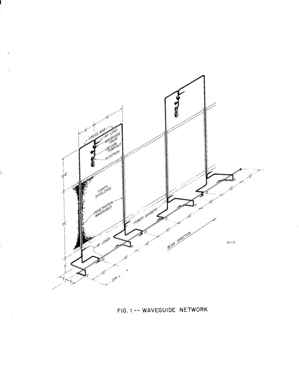
4 measurement method for a large network usually requires that a long, phasestable, return path be provided from the output port of the network back to the phase measurement system. Often with both methods,effects due to small, undesired, CW reflections and unequal, circuit attenuation can be minimized by modulating the signal. A more complete discussion of various phase length l-7 measuring techniques is given by Lacy, and others. The problem of adjusting the phase length of the 240 rectangular waveguide feed networks for Stanford s two-mile linear accelerator was solved by using 8 a modulated reflection method, similar to one suggested by Schaeffer2 and later further developed and used by Swarup and Yang to adjust a radio astronomy antenna array. The accelerator utilizes a highpower,s-band, rectangular- waveguide network to feed rf energy from each 25 megawatt klystron amplifier through 25 feet of earth shielding to four, independently fed and terminated, 10 foot, disc-loaded, circular-waveguide, accelerator sections (Fig. 1). In operation an rf wave appears to move along the entire accelerator in a single coherent wave with a phase velocity equal to c. This condition requires that each accelerator section have an rf phase velocity equal to c at the operating frequency, 2856 MHz, and that the rf wave entering each section be phased correctly with respect to the bunched electron beam. Each klystron is 10 individually phased by an automatic system to obtain the correct phase relationship between the bunched beam and the wave in one particular accelerator section driven by that klystron. Thus, the high power waveguide feed network must be permanently adjusted so that when the wave is phased correctly with respect to the beam in that one accelerator section, it is phased correctly in the other three sections driven by that same klystron. Since the accelerator -3 -

5 rf input ports are spaced by an integral number of wavelengths (29)) the wave- guide network branches must be adjusted to be equal in phase length, or to differ by only an integral number of wavelengths. The modulated reflection method for phase adjustment uses an individually controlled reflector (modulator flange) at each of the four output ports. A 2856 MHz cw signal is fed to the input port of the waveguide network, then one reflector at a time is switched at a 1 khz rate, and each return signal is compared in quadrature with a much larger unmodulated reference signal. The resultant signal will exhibit no 1kHz amplitude modulation when the reference signal and the carrier of the modulated reflected signal are out of phase by ninety degrees. Meanwhile, the diodes in the other three modulator flanges are not switched, but dc biased to cause little reflection. This allows comparison of the phase lengths of the four branches, subject to the half-cycle ambiguity of the reflection method. The half-cycle ambiguity then is resolved by a transmission phase measurement, which uses the modulator flanges as coax-to-waveguide adapters and uses a long coaxial cable as the return path to the input port of the waveguide network. The particular problems encountered with the networks (see Fig. 1) are: its large physical size, its 6 db of power division per branch, and numerous, small mismatches of undetermined phase. The great length of the network branches requires that the phase-length dependent parameters (temperature, frequency, and dimensional tolerances) be stringently controlled. However, some of the temperature dependent effects tend to cancel, as they are nearly the same for all the branches of a network. Unequal attenuation and random, small, network reflections produce only second order phase measurement errors with the modulated reflection method. -4-

6 II. DESCRIPTION OF THE MEASUREMENT SYSTEM The phase length measurement system consists of four modulator flanges (Fig. 2)) connecting cables and the phasing machine console (Fig. 3). The circuit, including the network under measurement, is shown in Fig. 4. A vector diagram showing the relationship between the pertinent signals at the detector and the equations for those signals are given in Fig. 5. Equations (1)) (2) and (3) give the expressions for the cw reference signal, vr, the square wave modulated reflected signal, v m, and the resulting sum signal, vs, respectively. The microwave frequency is wc, and the reflector is switched at w m. The reference phase length from the signal generator to the detector is 7)) and the phase length from the generator through one branch of the network to the modulator flange and back to the detector is 0. The modulation index is m. Equation (4) gives the quadrature null conditions. Two things should be pointed out about Eq. (4). First, the null conditions are independent of the type of amplitude detection (linear, square law, etc. ), and secondly, the phase length 0 varies as twice the length of a branch. Thus, the phase shifter in Fig. 4 can be adjusted so that q is in quadrature with 0 for any network branch, if its length is any multiple of quarter wavelengths long. The quarter-cycle ambiguity can be resolved by noting (see the vector diagram of Fig. 5) that when 0 is increased by the phase shifter the resulting vector, vs, increases in amplitude if (0 - q) ~270 c$ and decreases when (8-7) z90 $. Whether vs increases or decreases is easily determined by synchronous detection; that is, by triggering the oscilloscope (Fig. 4) with a 1 khz signal from the modulator power supply and observing whether the 1 khz amplitude modulation of vs (at the crystal detector) is of the same phase as each of the four modulator flanges is energized in turn. -5-
) (2) and (3) give the expressions for the cw reference signal, vr, the square wave modulated reflected signal, v m, and the resulting sum signal, vs, respectively.")
7 The remaining half-cycle ambiguity is resolved by a transmission phase measurement, for which a 75foot coaxial cable serves as the return path from each modulator flange, one at a time, to the phasing machine console. The phase length instability of the coaxial cable prevents the transmission measurement from being accurate to better than 10 $. A reference signal and the transmitted signal are fed into the opposite ends of a standing wave detector, and the sliding probe indicates any shift in null position from branch to branch. By referring to Fig. 4 the signal paths may be traced for the three functions of the phasing machine console: coarse phase measurement (transmission method), fine phase measurement (modulated reflection method) and network input VSWR measurement. For coarse phase measurement the coaxial switches are set to the coarse phase position, and the waveguide switch is rotated to connect the standing wave detector to the waveguide network. The modulator power supply performs three functions: it 1 khz square wave modulates the signal from the 2856 MHz signal generator, it reverse biases the appropriate modulator flange through the dc isolation tee, and it forward biases the other three modulator flanges directly. A frequency counter and power meter monitor the signal before it enters the 1 khz modulator. A 43dB directional coupler shunts a small reference signal through an isolator into the standing wave detector. Most of the signal passes through the 75-foot coaxial cable to a dc isolation tee and through the reverse biased modulator (now serving as a coax-to-waveguide adapter) to one branch of the waveguide network. The signal then passes through the waveguide network, through a variable attenuator, and into one end of the standing wave detector. The variable attenuator is used to equalize the amplitudes of the transmitted signal and the oppositely-traveling reference signal, and thus to produce a -6-

8 sharp null in the standing wave pattern. Comparing the positions of the nulls for the four branches gives a direct comparison of the phase length differences. For fine phase measurements the coaxial switches are put in the fine phase position, and the waveguide switch is rotated to connect the main waveguide circuit to the network. The modulator power supply is used to synchronize the oscil- loscope, to switch one of the modulator flanges at a 1 khz rate, and to forward- bias the others. A cw signal enters the waveguide and most of it passes directly to a magic tee and detector; this is the reference signal, vr. The first waveguide directional coupler sends one tenth of the initial signal through a precision, calibrated, dielectric-slab, phase shifter and a waveguide switch to the waveguide network. The modulator flanges at the end of the network are switched, one at a time; so that a small amplitude modulated signal is reflected back into the wave- guide switch, after which a second waveguide directional coupler sends one hundredth of the signal to the magic tee and the detector. At the detector the modulated, reflected signal, vm, is about 52 db below the reference signal vr. The phase shifter is adjusted to produce a null in the 1 khz amplitude modulation of the sum signal, vs. The differences in the phase shifter readings for the four branches of the network are direct measures of the phase length differences. A standing wave indicator conveniently doubles as a 1 khz tuned amplifier for the detected amplitude modulation of the sum signal, which is then displayed on an oscilloscope. The oscilloscope indicates the null condition and also, by being synchronized by the modulator power supply, indicates the relative sign of the 1 khz modulation term and thus removes the quarter-cycle ambiguity -7-

9 associated with the modulated reflection method. The standing wave detector also is used to measure the input VSWR to the network. An additional waveguide switch allows mounting of a reference modulator flange,which can be used to calibrate a set of four flanges relative to each other and to monitor any drift of the phasing machine. The modulator flange (Fig. 2) consists of a diode switch mounted in a special, stainless-steel, vacuum sealing, S-band waveguide flange. The point contact germanium diode is spring loaded on the end of a post across the waveguide. Two adjustable tuning screws in the plane of the diode are used for matching. The tuning screws and the diode post, which connects to the center conductor of a TNC fitting on the flange circumference, are vacuum sealed with teflon O-rings. Thin gold plating on top of copper plating improves the calibration accuracy and the shelf life of the stainless steel flanges. When the flange is properly tuned, reverse biasing the diode creates a large shunt admittance across the waveguide, which results in ninety to ninety-five percent voltage reflection. Forward biasing creates a small shunt admittance, which results in ten to fifteen percent.. voltage reflection. The tuning screws are adjusted so that the phase of the sum of the small and large reflections are the same in all four modulators. The magnitude of the reflections determines the modulation index m, and the phase determines the modulator flange calibration value. Since the diodes exhibit a non-linear phase versus voltage characteristic, square wave modulation makes for easier understanding and analysis of the circuit. The modulator power supply switches the diode bias signal at a 1 khz rate from -20~ to +loo ma. When the diode is reverse biased, the modulator flange serves as a coax-to-waveguide adapter with stable phase characteristics and a transmission loss of about 20 db. -8-

10 Between the diode support post and the flange body, there is a capacitive reactance of about 1.4 ohms at 2856 MHz, which provides some isolation between the bias circuitry and the microwave reflector circuitry. Since the modulator flange is primarily a precision reflector, and only incidently a coax-to-waveguide adapter, the 20 db transmission loss is preferable to less isolation. Frequent recalibrations locate the position of the equivalent plane of reflection to better than +,O. 3 C#I. The major source of calibration error is the small movement of the internal parts of the flange modulator during its installation, which requires a small amount of bowing of the flange to make a satisfactory vacuum and rf seal. The critical parts are machined to tolerances of +_ inch. The modulator flange is definitely the most critical component of the system. Before the waveguide components are assembled, they are matched to a VSWR of better than 1.05 and isolators were used in the appropriate places. Two sections of flexible waveguide are used (Fig. 3) between the waveguide switch and the network and the waveguide switch and the standing wave detector for greater ease in connecting to a network. In the case of the standing wave detector, a three screw tuner was used to match the flexible waveguides and the waveguide switch. The flexible waveguide does not affect significantly the accuracy of the modulated reflection method. Ground loops, frequency drift, temperature fluctuations, and modulator calibration accuracy are the major sources of phase adjustment error. If this type of system is to be used over a range of frequencies and for absolute phase length measurements a good deal of care would be required in its design and calibration. However, many of the mismatches and component phase characteristics are not detrimental when the system is operated at a single frequency and as a null comparison meter. -9-

11 I HI. RESULTS AND LIMITATIONS OF THE MEASUREMENTS Phase length measurements and adjustmets were made on 240 networks. The branches of any single network are from 59 to 70 feet long (118 to 140 guide wavelengths), and there are seven, vacuum tight, copper gasket joints along each branch. The waveguide components were tuned for minimum VSWR before installation, but is was necessary to adjust the phase of the networks after its final installation because of their great length, their numerous joints, and their sensitivity to temperature and vacuum conditions. The ten-foot accelerator sections were included between the modulator flanges and the output ports of the waveguide network (Fig. 4)) so the network would not have to be moved or connected after its adjustment. Including the accelerator sections in the measurement was possible since their phase lengths were adjusted to within + 2.5O $I before installation. The biggest problem was maintaining their temperature. Figure 6 shows the phase length dependency of a network and an accelerator section. The phase length of an accelerator section is seen to be eight to ten times more sensitive to temperature and frequency changes than a waveguide network branch. A water heating system that sets the accelerator sections and waveguide network temperatures nominally at 113OF is capable of maintaining a temperature difference between network branches of less than 0.75 F and between accelerator sections of less than 0.2 F for conditions of no rf power, such as during phase measurement. Phase length stability under accelerator operating conditions is more complex, and is treated elsewhere. 12 The measurement frequency is monitored with a frequency counter and maintained within 500 Hz of 2856 MHz. The network and accelerator sections are evacuated to less than 25 x loa (torr)

12 At this internal pressnre,changes in internal pressure do not affect appreciably the phase length, either by change in dielectric constant or by elastic deformation of the waveguide walls. However, elastic deformation, due to changes in external atmospheric (barometric) pressure, can cause measurable changes in phase length. These changes will be less than ( $)*(ft)- for 5% changes in barometric pressure. It is interesting to note, too, that the total effect of evacuating the system from 760 torr of dry N2 to less than 25 X 1O-3 torr is (O$)*(ft)-l for the rectangular waveguide and -280 (o$) for the ten foot accelerator section. 12 The total attenuation of the reflected signal, vm, is about 52 db greater than the reference signal, vr,. therefore, the quadrature null condition of Eq. (4) results in a (6-77) of not exactly 90 (o+) or 270 (O$), but ( a) or (o$). Thus, small variations in attenuation of less than a db from branch to branch cause less than 0.01 (O$) error. The waveguide network input VSWR after tuning is less than 1.2; this contributes a negligible error to this kind of modulated-reflection, null-comparison method. The actual phase adjustments are performed by permanently indenting the waveguide walls with special C-clamps with twelve-inch jaws. Smooth indentations over a length of several feet easily produce phase shifts up to the usually maximum variation between branches of 60 (O$). A few networks were out of adjustment by almost 180 O$ and required clamping over longer lengths to prevent significant reflections. Two operators in telephone communication easily made the remote adjustments. Bowing in of the narrow wall of the waveguide decreases its phase length, and bowing in of the broad wall (with consequent bowing out effects on the narrow wall) increases its phase length
*(ft)-l for the rectangular waveguide and -280 (o$) for the ten foot accelerator section.")
13 I The measurement system is capable of reproducing measurements within +_O. 1 ( $J). The modulator flanges have a calibration accuracy of better than +_O. 3 (O$). The networks have a phase stability of better than f0.5 ( $I). The accelerator sections are within t2.5 (O$J) of their design lengths. Thus, the overall accuracy of phase adjustment is better than +,4.5 (O$), allowing fl. 0 (O$) for temperature instabilities for the accelerator sections. Figure 7 shows the distribution of phase-unbalance of the waveguide components before tuning. Measurements were made, at most klystron stations of the phase- unbalance from the klystron port to the input port of the lower power divider; and at all stations, of the S-assemblies (the quarter-power portions of the rectangular waveguide network, including the lower power divider). Separate data are shown for S-assemblies at odd- and even-numbered klystron stations because of the alternating feed arrangement shown in Fig. 1. The data show that the rectangular waveguide cross-over branch is correctly designed, as its location in the network does not affect the mean phase-unbalance. The 15O $J mean unbalance did not warrant adjustment of the design of the rectangular waveguide network during manufacture. Ln conclusion, the modulated reflection scheme has been found to work very well on the large, single-input port, multi-output port, waveguide networks. The greatest errors come from limited control over the environmental parameters. The use of a diode for the modulated reflector is very satisfactory as long as the microwave power level at the diode was kept low (a few milliwatts). If this type of scheme is used at different frequencies, either to make absolute phase length measurements or to measure the phase versus frequency characteristics of a network, the reflector and the microwave comparison circuit must be broadbanded or calibrated as a function of frequency

14 I ACKNOWLEDGEMENTS The authors wish to express their appreciation to R. P. Borghi for suggesting the use of the modulated reflection technique and for initial assistance in executing the numerous ideas concerned with its design. The following people contributed significantly with advice, encouragement, or assistance: Messrs. V. G. Price, A. L. Eldredge, C. Rasmussen, A. Lisin, W. Pierce, G. Francois, R. Lam, M. Adams, J. Pope, K. Doty and A. Fiedor

15 REFERENCES 1. P. Lacy, Analysis and Measurement of Phase Characteristics in Microwave Systems, I 1961 Weston Convention Record 5, part 23, paper G. E. Schafer, A Modulated Subcarrier Technique of Measuring Microwave Phase Shifts, IRE Trans. on Instrumentation 1-9, (1960). 3. M. Magid, Precision Microwave Phase Shift Measurements, I IRE Trans. on Instrumentation l-7, (1958). 4. S. D. Robertson, A Method of Measuring Phase at Microwave Frequencies, BSTJ &8, (1949). 5. R. J. King, An Amplitude and Phase Measuring System Using a Small Modulated Scatterer, Microwave Journal g, No. 4, 51 (1965). 6. P. Lacy, A Versatile Phase Measurement Method for Transmission-Line Networks, IRE Trans. MTT 2, (1961). 7. E. N. Phillips, The Uncertainties of Phase Measurement, Microwaves 4, No. 2, 14-21, (1965). 8. R. Alvarez, R. P. Borghi, and J. N. Weaver, Precision Phase Adjustment of a Linear Accelerator High Power Waveguide Feed Network, IEEE Trans. on Nuclear Science 12, No. 3, (1965). 9. G. Swarup and K. S. Yang, Phase Adjustment of Large Antennas, IRE Trans. on Antennas and Propagation 2, (1961). 10. C. B. Williams, et al., The Automatic Phasing System for the Stanford Two-Mile Linear Electron Accelerator, SLAC -PUB-104, May
. 6. P. Lacy, A Versatile Phase Measurement Method for Transmission-Line Networks, IRE Trans.")
16 11. K. E. Mortenson, Microwave Semiconductor Control Devices, Microwave Journal 7, No. 5, (1964). 12. J. N. Weaver, Microwave Phase Dependence of the Accelerator Sections and the Waveguide Network, It SLAC-TN-66-6, May
. 12. J. N.")
17 I I c 0 m
18 FIG MODULATOR FLANGE

19

20 . DETECTOR FINE-+ VSWR & COARSE A DlRiCVTC;:NAL 1 ISOLATOR -I.-- --iifter TIONAL,,,PLER t STANDING WAVE INDICATOR FREQUENCY POWER COUNTER METER. J 1 SQUARE 1 I WAVE ---I SIGNAL VSWR A COAX - FINE-Q, DIRECTIONAL WAVEGU I DE SWITCHES- l&l T 8 RF ATION EE c,r%? f-+.- MODUCATOR POWER, w--e 1 SUPPLY 1 -xd i WAVEGU I DE -1 I I + TUNER 1 J, LREFERENCE MODULATOR FLANGE ~COARSE - +, ATTENUATOR OTNOE M OFDLUI.iT; R -El== f. STANDING WAVE DETECTOR FIG BLOCK DIAGRAM OF PHASING MACHINE

21 481-2-A vr=vrcos (bp?) (1) vm = vm [(ql) +F g cos;;;;;umt ] cos(o,t +e) (2) dc terms + 7T vm + vr cos(&r)) + harmonic terms}1 2 cos [uct + a(w,t, rl,e)] 3 cos bjmt (3) A null in the amplitude modulation of vs at the frequency wm occurs for $EL vm + vr cos (f3-r)) = 0 ( ) or where O<m<l and vm <c vr. Fig. 5--Equations and vector diagram showing quadrature null conditions.
22 Phase Coefficient efo (o$ 70 feet I I Waveguide Network Branch 10 foot Accelerator Section A Fig. g--phase length coefficients
23 PHASE-LENGTH UNBALANCE TO LOWER POWER DIVIDER I I i / ; PHASE-LENGTH UNBALANCE OF ODD-NUMBERED S-ASSEMBLIES : I 4 '2 ) r J f ; PHASE-LENGTH UNBALANCE OF EVEN-NUMBERED S-ASSEMBLIES 3 60" 50" 40' 30' 20' loo 0 -TARGET END ELECTRICALLY LONGER i I I 10" 20' 30" 40' 50' 60" INJECTOR END- ELECTRICALLY LONGER B FIG. 7- GRAPHS OF PHASE LENGTH ERRORS DUE TO MANUFACTURING TOLERANCES.
Vector Network Analyzer Techniques to Measure WR340 Waveguide Windows
 LS-296 Vector Network Analyzer Techniques to Measure WR340 Waveguide Windows T. L. Smith ASD / RF Group Advanced Photon Source Argonne National Laboratory June 26, 2002 Table of Contents 1) Introduction
1. The Slotted Line. ECE 584 Microwave Engineering Laboratory Experiments. Introduction:
 ECE 584 Microwave Engineering Laboratory Experiments 1. The Slotted Line Introduction: In this experiment we will use a waveguide slotted line to study the basic behavior of standing waves and to measure
Engineering Sciences 151. Electromagnetic Communication Laboratory Assignment 3 Fall Term 1998-99
 Engineering Sciences 151 Electromagnetic Communication Laboratory Assignment 3 Fall Term 1998-99 WAVE PROPAGATION II: HIGH FREQUENCY SLOTTED LINE AND REFLECTOMETER MEASUREMENTS OBJECTIVES: To build greater
E. K. A. ADVANCED PHYSICS LABORATORY PHYSICS 3081, 4051 NUCLEAR MAGNETIC RESONANCE
 E. K. A. ADVANCED PHYSICS LABORATORY PHYSICS 3081, 4051 NUCLEAR MAGNETIC RESONANCE References for Nuclear Magnetic Resonance 1. Slichter, Principles of Magnetic Resonance, Harper and Row, 1963. chapter
14.5GHZ 2.2KW CW GENERATOR. GKP 22KP 14.5GHz WR62 3x400V
 14.5GHZ 2.2KW CW GENERATOR GKP 22KP 14.5GHz WR62 3x400V UTILIZATION OF GKP 22KP GENERATOR With its characteristics of power stability whatever the load, very fast response time at a pulse, low ripple,
RF SYSTEM FOR VEPP-5 DAMPING RING
 Ó³ Ÿ. 2006.. 3, º 7(136).. 60Ä64 Š 621.384.634.14 RF SYSTEM FOR VEPP-5 DAMPING RING Ye. Gusev, N. Kot, S. Krutikhin, I. Kuptsov, G. Kurkin, I. Makarov, N. Matyash, L. Mironenko, S. Motygin, V. Osipov,
RF Network Analyzer Basics
 RF Network Analyzer Basics A tutorial, information and overview about the basics of the RF Network Analyzer. What is a Network Analyzer and how to use them, to include the Scalar Network Analyzer (SNA),
Experiment 7: Familiarization with the Network Analyzer
 Experiment 7: Familiarization with the Network Analyzer Measurements to characterize networks at high frequencies (RF and microwave frequencies) are usually done in terms of scattering parameters (S parameters).
SIGNAL GENERATORS and OSCILLOSCOPE CALIBRATION
 1 SIGNAL GENERATORS and OSCILLOSCOPE CALIBRATION By Lannes S. Purnell FLUKE CORPORATION 2 This paper shows how standard signal generators can be used as leveled sine wave sources for calibrating oscilloscopes.
Technical Datasheet Scalar Network Analyzer Model 8003-10 MHz to 40 GHz
 Technical Datasheet Scalar Network Analyzer Model 8003-10 MHz to 40 GHz The Giga-tronics Model 8003 Precision Scalar Network Analyzer combines a 90 db wide dynamic range with the accuracy and linearity
MEASUREMENT UNCERTAINTY IN VECTOR NETWORK ANALYZER
 MEASUREMENT UNCERTAINTY IN VECTOR NETWORK ANALYZER W. Li, J. Vandewege Department of Information Technology (INTEC) University of Gent, St.Pietersnieuwstaat 41, B-9000, Gent, Belgium Abstract: Precision
0HDVXULQJWKHHOHFWULFDOSHUIRUPDQFH FKDUDFWHULVWLFVRI5),)DQGPLFURZDYHVLJQDO SURFHVVLQJFRPSRQHQWV
,)DQGPLFURZDYHVLJQDO SURFHVVLQJFRPSRQHQWV") 0HDVXULQJWKHHOHFWULFDOSHUIRUPDQFH FKDUDFWHULVWLFVRI5),)DQGPLFURZDYHVLJQDO SURFHVVLQJFRPSRQHQWV The treatment given here is introductory, and will assist the reader who wishes to consult the standard texts
0HDVXULQJWKHHOHFWULFDOSHUIRUPDQFH FKDUDFWHULVWLFVRI5),)DQGPLFURZDYHVLJQDO SURFHVVLQJFRPSRQHQWV The treatment given here is introductory, and will assist the reader who wishes to consult the standard texts
Understanding Mixers Terms Defined, and Measuring Performance
 Understanding Mixers Terms Defined, and Measuring Performance Mixer Terms Defined Statistical Processing Applied to Mixers Today's stringent demands for precise electronic systems place a heavy burden
"FP", "FR", "FQ" Series Bandpass Filters
 Description "FP", "FR", "FQ" Series Bandpass Filters The tuning instructions described on the following pages apply to all 7, 8.5, and 10 Bandpass, Notch, and Q circuit filters. Typical models and electrical
Selecting a Transmission Line for Your Broadcast System
 Selecting a Transmission Line for Your Broadcast System Introduction This Bulletin presents the procedures broadcasters need for calculating attenuation and power handling parameters to properly design
Shielding Effectiveness Test Method. Harbour s LL, SB, and SS Coaxial Cables. Designs for Improved Shielding Effectiveness
 Shielding Effectiveness Test Method Harbour s LL, SB, and SS Coaxial Cables Designs for Improved Shielding Effectiveness Harbour Industries 4744 Shelburne Road Shelburne Vermont 05482 USA 802-985-3311
75 Ω Transmission System
 NRAO NTC-DSL Laboratory Report Dynamic Spectroscopy Laboratory Report Series Report 03 September, 2006 75 Ω Transmission System Chaitali R. Parashare Department of Electrical and Computer Engineering,
Antenna Properties and their impact on Wireless System Performance. Dr. Steven R. Best. Cushcraft Corporation 48 Perimeter Road Manchester, NH 03013
 Antenna Properties and their impact on Wireless System Performance Dr. Steven R. Best Cushcraft Corporation 48 Perimeter Road Manchester, NH 03013 Phone (603) 627-7877 FAX: (603) 627-1764 Email: sbest@cushcraft.com
Keysight Technologies Understanding the Fundamental Principles of Vector Network Analysis. Application Note
 Keysight Technologies Understanding the Fundamental Principles of Vector Network Analysis Application Note Introduction Network analysis is the process by which designers and manufacturers measure the
Agilent De-embedding and Embedding S-Parameter Networks Using a Vector Network Analyzer. Application Note 1364-1
 Agilent De-embedding and Embedding S-Parameter Networks Using a Vector Network Analyzer Application Note 1364-1 Introduction Traditionally RF and microwave components have been designed in packages with
Understanding SWR by Example
 Understanding SWR by Example Take the mystery and mystique out of standing wave ratio. Darrin Walraven, K5DVW It sometimes seems that one of the most mysterious creatures in the world of Amateur Radio
Current Probes. User Manual
 Current Probes User Manual ETS-Lindgren L.P. reserves the right to make changes to any product described herein in order to improve function, design, or for any other reason. Nothing contained herein shall
MAINTENANCE & ADJUSTMENT
 MAINTENANCE & ADJUSTMENT Circuit Theory The concept of PLL system frequency synthesization is not of recent development, however, it has not been a long age since the digital theory has been couplet with
Times Microwave Systems Hermetically Sealed Assemblies
 SCOPE This Specification details the Electrical, Mechanical and Environmental Characteristics of Times Microwave Systems MILTECH 340.34 Diameter Hermetically Sealed Coaxial Transmission Lines. This product
102 26-m Antenna Subnet Telecommunications Interfaces
 DSMS Telecommunications Link Design Handbook 26-m Antenna Subnet Telecommunications Interfaces Effective November 30, 2000 Document Owner: Approved by: Released by: [Signature on file in TMOD Library]
S-Band Low Noise Amplifier Using the ATF-10136. Application Note G004
 S-Band Low Noise Amplifier Using the ATF-10136 Application Note G004 Introduction This application note documents the results of using the ATF-10136 in low noise amplifier applications at S band. The ATF-10136
Cable Analysis and Fault Detection using the Bode 100
 Cable Analysis and Fault Detection using the Bode 100 By Stephan Synkule 2014 by OMICRON Lab V1.3 Visit www.omicron-lab.com for more information. Contact support@omicron-lab.com for technical support.
WAVEGUIDE-COAXIAL LINE TRANSITIONS
 WAVEGUIDE-COAXIAL LINE TRANSITIONS 1. Overview Equipment at microwave frequencies is usually based on a combination of PCB and waveguide components. Filters and antennas often use waveguide techniques,
Germanium Diode AM Radio
 Germanium Diode AM Radio LAB 3 3.1 Introduction In this laboratory exercise you will build a germanium diode based AM (Medium Wave) radio. Earliest radios used simple diode detector circuits. The diodes
RF and Microwave Accessories. CD-ROM Catalog. Find the right component for your Rohde & Schwarz test & measurement equipment
 RF and Microwave Accessories CD-ROM Catalog Find the right component for your Rohde & Schwarz test & measurement equipment Product group Typical applications Adapters Interchanging of various connector
Application Note. So You Need to Measure Some Inductors?
 So You Need to Measure Some nductors? Take a look at the 1910 nductance Analyzer. Although specifically designed for production testing of inductors and coils, in addition to measuring inductance (L),
NUCLEAR MAGNETIC RESONANCE. Advanced Laboratory, Physics 407, University of Wisconsin Madison, Wisconsin 53706
 (revised 4/21/03) NUCLEAR MAGNETIC RESONANCE Advanced Laboratory, Physics 407, University of Wisconsin Madison, Wisconsin 53706 Abstract This experiment studies the Nuclear Magnetic Resonance of protons
DRAFT. University of Pennsylvania Moore School of Electrical Engineering ESE319 Electronic Circuits - Modeling and Measurement Techniques
 University of Pennsylvania Moore School of Electrical Engineering ESE319 Electronic Circuits - Modeling and Measurement Techniques 1. Introduction. Students are often frustrated in their attempts to execute
DEPARTMENT OF DEFENSE TEST METHOD STANDARD METHOD OF INSERTION LOSS MEASUREMENT
 INCH-POUND MIL-STD-220C 14 May 2009 SUPERSEDING MIL-STD-220B 24 January 2000 DEPARTMENT OF DEFENSE TEST METHOD STANDARD METHOD OF INSERTION LOSS MEASUREMENT AMSC N/A FSC EMCS FOREWORD 1. This standard
Agilent PN 8753-1 RF Component Measurements: Amplifier Measurements Using the Agilent 8753 Network Analyzer. Product Note
 Agilent PN 8753-1 RF Component Measurements: Amplifier Measurements Using the Agilent 8753 Network Analyzer Product Note 2 3 4 4 4 4 6 7 8 8 10 10 11 12 12 12 13 15 15 Introduction Table of contents Introduction
Just a Dipole. Gary Wescom N0GW July 16, 2007
 Just a Dipole Gary Wescom N0GW July 16, 2007 Often we will hear people describing their antennas as just a dipole. After all, a coax cable fed, half wavelength dipole is one of the simplest antennas to
The W5JCK Guide to the Mathematic Equations Required for the Amateur Extra Class Exam
 The W5JCK Guide to the Mathematic Equations Required for the Amateur Extra Class Exam This document contains every question from the Extra Class (Element 4) Question Pool* that requires one or more mathematical
Agilent AN 1316 Optimizing Spectrum Analyzer Amplitude Accuracy
 Agilent AN 1316 Optimizing Spectrum Analyzer Amplitude Accuracy Application Note RF & Microwave Spectrum Analyzers Table of Contents 3 3 4 4 5 7 8 8 13 13 14 16 16 Introduction Absolute versus relative
UNDERSTANDING NOISE PARAMETER MEASUREMENTS (AN-60-040)
") UNDERSTANDING NOISE PARAMETER MEASUREMENTS (AN-60-040 Overview This application note reviews noise theory & measurements and S-parameter measurements used to characterize transistors and amplifiers at
UNDERSTANDING NOISE PARAMETER MEASUREMENTS (AN-60-040 Overview This application note reviews noise theory & measurements and S-parameter measurements used to characterize transistors and amplifiers at
KLYSTRON TUNING PROCEDURES:
 KLYSTRON TUNING PROCEDURES: Applicable to 5-Cavity C-Band and Ku-band Klystrons made by CPI Canada. General. The channel tuning mechanism, an integral part of the tube, provides for the precise tuning
Impedance 50 (75 connectors via adapters)
") VECTOR NETWORK ANALYZER PLANAR TR1300/1 DATA SHEET Frequency range: 300 khz to 1.3 GHz Measured parameters: S11, S21 Dynamic range of transmission measurement magnitude: 130 db Measurement time per point:
VECTOR NETWORK ANALYZER PLANAR TR1300/1 DATA SHEET Frequency range: 300 khz to 1.3 GHz Measured parameters: S11, S21 Dynamic range of transmission measurement magnitude: 130 db Measurement time per point:
Using Simple Calibration Load Models to Improve Accuracy of Vector Network Analyzer Measurements
 Using Simple Calibration Load Models to Improve Accuracy of Vector Network Analyzer Measurements Nick M. Ridler 1 and Nils Nazoa 2 1 National Physical Laboratory, UK (www.npl.co.uk) 2 LA Techniques Ltd,
Improving Network Analyzer Measurements of Frequency-translating Devices Application Note 1287-7
 Improving Network Analyzer Measurements of Frequency-translating Devices Application Note 1287-7 - + - + - + - + Table of Contents Page Introduction......................................................................
Active Vibration Isolation of an Unbalanced Machine Spindle
 UCRL-CONF-206108 Active Vibration Isolation of an Unbalanced Machine Spindle D. J. Hopkins, P. Geraghty August 18, 2004 American Society of Precision Engineering Annual Conference Orlando, FL, United States
T = 1 f. Phase. Measure of relative position in time within a single period of a signal For a periodic signal f(t), phase is fractional part t p
, phase is fractional part t p") Data Transmission Concepts and terminology Transmission terminology Transmission from transmitter to receiver goes over some transmission medium using electromagnetic waves Guided media. Waves are guided
Data Transmission Concepts and terminology Transmission terminology Transmission from transmitter to receiver goes over some transmission medium using electromagnetic waves Guided media. Waves are guided
2. The Vector Network Analyzer
 ECE 584 Laboratory Experiments 2. The Vector Network Analyzer Introduction: In this experiment we will learn to use a Vector Network Analyzer to measure the magnitude and phase of reflection and transmission
Agilent 8510-13 Measuring Noninsertable Devices
 Agilent 8510-13 Measuring Noninsertable Devices Product Note A new technique for measuring components using the 8510C Network Analyzer Introduction The majority of devices used in real-world microwave
Understanding Power Splitters
 Understanding Power Splitters how they work, what parameters are critical, and how to select the best value for your application. Basically, a 0 splitter is a passive device which accepts an input signal
Michael Hiebel. Fundamentals of Vector Network Analysis
 Michael Hiebel Fundamentals of Vector Network Analysis TABIH OF CONTENTS Table of contents 1 Introduction 12 1.1 What is a network analyzer? 12 1.2 Wave quantities and S-parameters 13 1.3 Why vector network
Application Note Noise Frequently Asked Questions
 : What is? is a random signal inherent in all physical components. It directly limits the detection and processing of all information. The common form of noise is white Gaussian due to the many random
RF measurements, tools and equipment E. B. Boskamp, A. Nabetani, J. Tropp (eddy.boskamp@med.ge.com)
") RF measurements, tools and equipment E. B. Boskamp, A. Nabetani, J. Tropp (eddy.boskamp@med.ge.com) INTRODUCTION I am often asked by researchers what kind of equipment is needed to set up an RF lab. The
RF measurements, tools and equipment E. B. Boskamp, A. Nabetani, J. Tropp (eddy.boskamp@med.ge.com) INTRODUCTION I am often asked by researchers what kind of equipment is needed to set up an RF lab. The
Jeff Thomas Tom Holmes Terri Hightower. Learn RF Spectrum Analysis Basics
 Jeff Thomas Tom Holmes Terri Hightower Learn RF Spectrum Analysis Basics Learning Objectives Name the major measurement strengths of a swept-tuned spectrum analyzer Explain the importance of frequency
CCTV System Troubleshooting Guide
 Wouldn t be nice to start and finish a CCTV System Project without running into any problems before, during and after the installation is completed. Well, in this article we will try and explain why we
Understanding the Fundamental Principles of Vector Network Analysis. Application Note 1287-1. Table of Contents. Page
 Understanding the Fundamental Principles of Vector Network Analysis Application Note 1287-1 Table of Contents Page Introduction 2 Measurements in Communications Systems 2 Importance of Vector Measurements
Standex-Meder Electronics. Custom Engineered Solutions for Tomorrow
 Standex-Meder Electronics Custom Engineered Solutions for Tomorrow RF Reed Relays Part II Product Training Copyright 2013 Standex-Meder Electronics. All rights reserved. Introduction Purpose Designing
A Low Frequency Adapter for your Vector Network Analyzer (VNA)
") Jacques Audet, VE2AZX 7525 Madrid St, Brossard, QC, Canada J4Y G3: jacaudet@videotron.ca A Low Frequency Adapter for your Vector Network Analyzer (VNA) This compact and versatile unit extends low frequency
Jacques Audet, VE2AZX 7525 Madrid St, Brossard, QC, Canada J4Y G3: jacaudet@videotron.ca A Low Frequency Adapter for your Vector Network Analyzer (VNA) This compact and versatile unit extends low frequency
DDX 7000 & 8003. Digital Partial Discharge Detectors FEATURES APPLICATIONS
 DDX 7000 & 8003 Digital Partial Discharge Detectors The HAEFELY HIPOTRONICS DDX Digital Partial Discharge Detector offers the high accuracy and flexibility of digital technology, plus the real-time display
Coaxial Cable Products Guide. Connectivity for Business-Critical Continuity
 Coaxial Cable Products Guide Connectivity for Business-Critical Continuity The Difference Starts With The Cable BULK CABLES SLA Series Lowest loss cable available to 18 GHz, best choice for critical applications
DDX 7000 & 8003. Digital Partial Discharge Detectors FEATURES APPLICATIONS
 DDX 7000 & 8003 Digital Partial Discharge Detectors The HAEFELY HIPOTRONICS DDX Digital Partial Discharge Detector offers the high accuracy and flexibility of digital technology, plus the real-time display
Clock Recovery in Serial-Data Systems Ransom Stephens, Ph.D.
 Clock Recovery in Serial-Data Systems Ransom Stephens, Ph.D. Abstract: The definition of a bit period, or unit interval, is much more complicated than it looks. If it were just the reciprocal of the data
Differential-Hall-Effect based Sensors Series A5S
 Speed and Frequency Seite 1 von 6 Differential-Hall-Effect based Sensors Series A5S Outstanding Characteristics Speed range covering most demands: from close to zero up to 25,000 pulses/second (response
Application Guide to RF Coaxial Connectors and Cables
 Application Guide to RF Coaxial Connectors and Cables By: Michael J. Hannon Product Applications Engineer and Pat Malloy, Sr. Applications Engineer There is a wide variety of coaxial connectors and cables
RX-AM4SF Receiver. Pin-out. Connections
 RX-AM4SF Receiver The super-heterodyne receiver RX-AM4SF can provide a RSSI output indicating the amplitude of the received signal: this output can be used to create a field-strength meter capable to indicate
Impedance Matching and Matching Networks. Valentin Todorow, December, 2009
 Impedance Matching and Matching Networks Valentin Todorow, December, 2009 RF for Plasma Processing - Definition of RF What is RF? The IEEE Standard Dictionary of Electrical and Electronics Terms defines
Precision Diode Rectifiers
 by Kenneth A. Kuhn March 21, 2013 Precision half-wave rectifiers An operational amplifier can be used to linearize a non-linear function such as the transfer function of a semiconductor diode. The classic
Calculating Antenna System Return Loss As Viewed Through The RF Path
 Calculating Antenna System Return Loss As Viewed Through The RF Path Lou Meyer, Director of Technical Marketing December 2009 1. Introduction Return loss (RL), reflection coefficient (Γ) and voltage standing
Curriculum and Concept Module Development in RF Engineering
 Introduction Curriculum and Concept Module Development in RF Engineering The increasing number of applications students see that require wireless and other tetherless network solutions has resulted in
Applications in EMC testing. Outline. Antennas for EMC Testing. Terminology
 Antennas for EMC Testing Zhong Chen ETS-Lindgren 1301 Arrow Point Drive Cedar Park, TX 78613 Zhong.Chen@ets-lindgren.com Outline EMC Terms and Definitions Typical EMC Antennas Calibration of EMC Antennas
Performing Amplifier Measurements with the Vector Network Analyzer ZVB
 Product: Vector Network Analyzer R&S ZVB Performing Amplifier Measurements with the Vector Network Analyzer ZVB Application Note This document describes typical measurements that are required to be made
W-band vector network analyzer based on an audio lock-in amplifier * Abstract
 ARDB 179 SLAC PUB 7884 July 1998 W-band vector network analyzer based on an audio lock-in amplifier * R. H. Siemann Stanford Linear Accelerator Center, Stanford University, Stanford CA 94309 Abstract The
W1 Connector W1 Adapter W1 Termination
 Data Sheet W1 Connector W1 Adapter W1 Termination DC to 110 GHz A complete coaxial connector system with mode-free performance to 110 GHz Features Excellent RF Performance to 110 GHz 50Ω Impedance Low
GenTech Practice Questions
 GenTech Practice Questions Basic Electronics Test: This test will assess your knowledge of and ability to apply the principles of Basic Electronics. This test is comprised of 90 questions in the following
MATRIX TECHNICAL NOTES
 200 WOOD AVENUE, MIDDLESEX, NJ 08846 PHONE (732) 469-9510 FAX (732) 469-0418 MATRIX TECHNICAL NOTES MTN-107 TEST SETUP FOR THE MEASUREMENT OF X-MOD, CTB, AND CSO USING A MEAN SQUARE CIRCUIT AS A DETECTOR
Diode Applications. by Kenneth A. Kuhn Sept. 1, 2008. This note illustrates some common applications of diodes.
 by Kenneth A. Kuhn Sept. 1, 2008 This note illustrates some common applications of diodes. Power supply applications A common application for diodes is converting AC to DC. Although half-wave rectification
spinner Measurement & Calibration equipment for network analyzers
 spinner Measurement & Calibration equipment for network analyzers Edition B 2011 High Frequency Performance Worldwide www.spinner-group.com SPINNER test & calibration equipment for best measurement results
Application Note SAW-Components
 Application Note SAW-Components Principles of SAWR-stabilized oscillators and transmitters. App: Note #1 This application note describes the physical principle of SAW-stabilized oscillator. Oscillator
Current Probes, More Useful Than You Think
 Current Probes, More Useful Than You Think Training and design help in most areas of Electrical Engineering Copyright 1998 Institute of Electrical and Electronics Engineers. Reprinted from the IEEE 1998
LOW COST MOTOR PROTECTION FILTERS FOR PWM DRIVE APPLICATIONS STOPS MOTOR DAMAGE
 LOW COST MOTOR PROTECTION FILTERS FOR PWM DRIVE APPLICATIONS STOPS MOTOR DAMAGE Karl M. Hink, Executive Vice President Originally presented at the Power Quality 99 Conference ABSTRACT Motor protection
Sound Power Measurement
 Sound Power Measurement A sound source will radiate different sound powers in different environments, especially at low frequencies when the wavelength is comparable to the size of the room 1. Fortunately
Automatic compression measurement using network analyzers
 Automatic compression measurement using network analyzers Introduction The dynamic range of an amplifier is determined by noise figure and compression. In multi carrier applications third order intercept
Critical thin-film processes such as deposition and etching take place in a vacuum
 WHITEPAPER INTRODUCING POWER SUPPLIES AND PLASMA Critical thin-film processes such as deposition and etching take place in a vacuum SYSTEMS chamber in the presence of a plasma. A plasma is an electrically
Embedded FM/TV Antenna System
 1 Embedded FM/TV Antenna System Final Report Prepared for By January 21, 2011 2 Table of Contents 1 Introduction... 5 2 Technical Specification... 6 3 Prototype Antenna... 7 4 FASTROAD Active module fabrication...
AUTOMATIC NETWORK ANALYZER PROCEDURES FOR 5045 KLYSTRON CAVITIES * J.G. Judkins
 Introduction SLAC-TN-91-10 July 1991 AUTOMATIC NETWORK ANALYZER PROCEDURES FOR 5045 KLYSTRON CAVITIES * J.G. Judkins Stanford Linear Accelerator Center Stanford University, Stanford, CA 94309 This Note
Wireless RF Distribution in Buildings using Heating and Ventilation Ducts
 Wireless RF Distribution in Buildings using Heating and Ventilation Ducts Christopher P. Diehl, Benjamin E. Henty, Nikhil Kanodia, and Daniel D. Stancil Department of Electrical and Computer Engineering
TOTALLY SOLID STATE NON-DIRECTIONAL RADIO BEACONS 190-535 khz
 TOTALLY SOLID STATE NON-DIRECTIONAL RADIO S 190-535 khz This family of radio transmitters has been developed as extremely efficient, highly reliable Non Directional Beacons. ND2000A/4000A» MODULAR CONSTRUCTION»
APPLICATION NOTE ULTRASONIC CERAMIC TRANSDUCERS
 APPLICATION NOTE ULTRASONIC CERAMIC TRANSDUCERS Selection and use of Ultrasonic Ceramic Transducers The purpose of this application note is to aid the user in the selection and application of the Ultrasonic
Interference to Hearing Aids by Digital Mobile Telephones Operating in the 1800 MHz Band.
 Interference to Hearing Aids by Digital Mobile Telephones Operating in the 1800 MHz Band. Reference: EB968 Date: January 2008 Author: Eric Burwood (National Acoustic Laboratories) Collaborator: Walter
R&S ZCxxx Millimeter-Wave Converters Specifications
 ZCxxx_dat-sw_en_3607-1471-22_v0200_cover.indd 1 Data Sheet 02.00 Test & Measurement R&S ZCxxx Millimeter-Wave Converters Specifications 21.07.2015 15:09:16 CONTENTS Definitions... 3 General information...
Antenna Basic Concepts
 ANTENNA An antenna is a device to transmit and/or receive electromagnetic waves. Electromagnetic waves are often referred to as radio waves. Most antennas are resonant devices, which operate efficiently
A wave lab inside a coaxial cable
 INSTITUTE OF PHYSICS PUBLISHING Eur. J. Phys. 25 (2004) 581 591 EUROPEAN JOURNAL OF PHYSICS PII: S0143-0807(04)76273-X A wave lab inside a coaxial cable JoãoMSerra,MiguelCBrito,JMaiaAlves and A M Vallera
'' EGGBEATER '' ANTENNA VHF/UHF ~ PART 2
 '' EGGBEATER '' ANTENNA VHF/UHF ~ PART 2 ON6WG / F5VIF Summary Note : In Part 1, Fig 1 shows a maximum gain of 6.45 dbi. Several design attempts were made using slightly different configurations ( i.e.
Receiver Multicoupler & R.F. Preselectors
 By: William F. Lieske, Sr. Founder, EMR Corporation Background Information For more than twenty-five years the number of multi-channel wireless land mobile equipment sites has proliferated. To accommodate
Selecting Receiving Antennas for Radio Tracking
 Selecting Receiving Antennas for Radio Tracking Larry B Kuechle, Advanced Telemetry Systems, Inc. Isanti, Minnesota 55040 lkuechle@atstrack.com The receiving antenna is an integral part of any radio location
APPLICATION NOTES POWER DIVIDERS. Things to consider
 Internet Copy Rev A Overview Various RF applications require power to be distributed among various paths. The simplest way this can be done is by using a power splitter/divider. Power dividers are reciprocal
Harmonics and Noise in Photovoltaic (PV) Inverter and the Mitigation Strategies
 Inverter and the Mitigation Strategies") Soonwook Hong, Ph. D. Michael Zuercher Martinson Harmonics and Noise in Photovoltaic (PV) Inverter and the Mitigation Strategies 1. Introduction PV inverters use semiconductor devices to transform the
Soonwook Hong, Ph. D. Michael Zuercher Martinson Harmonics and Noise in Photovoltaic (PV) Inverter and the Mitigation Strategies 1. Introduction PV inverters use semiconductor devices to transform the
Understanding Power Splitters
 Understanding Power Splitters How they work, what parameters are critical, and how to select the best value for your application. Basically, a 0 splitter is a passive device which accepts an input signal
S-Parameters and Related Quantities Sam Wetterlin 10/20/09
 S-Parameters and Related Quantities Sam Wetterlin 10/20/09 Basic Concept of S-Parameters S-Parameters are a type of network parameter, based on the concept of scattering. The more familiar network parameters
PUMPED Nd:YAG LASER. Last Revision: August 21, 2007
 PUMPED Nd:YAG LASER Last Revision: August 21, 2007 QUESTION TO BE INVESTIGATED: How can an efficient atomic transition laser be constructed and characterized? INTRODUCTION: This lab exercise will allow
Cable Impedance and Structural Return Loss Measurement Methodologies
 Cable Impedance and Structural Return Loss Measurement Methodologies Introduction Joe Rowell Joel Dunsmore and Les Brabetz Hewlett Packard Company Santa Rosa, California Two critical electrical specifications
Cumbria Designs T-1. SSB/CW Filter kit (4.9152MHz) User Manual
 User Manual") Cumbria Designs T-1 SSB/CW Filter kit (4.9152MHz) User Manual CONTENTS 1 INTRODUCTION 2 2 CIRCUIT DESCRIPTION 2 3 ASSEMBLY 2 4 TESTING 4 The Steading Stainton PENRITH Cumbria CA11 0ES UK 1 Introduction
Cumbria Designs T-1 SSB/CW Filter kit (4.9152MHz) User Manual CONTENTS 1 INTRODUCTION 2 2 CIRCUIT DESCRIPTION 2 3 ASSEMBLY 2 4 TESTING 4 The Steading Stainton PENRITH Cumbria CA11 0ES UK 1 Introduction