BUILDING A MATHEMATICS LABORATORY FOR TACTILE LEARNERS USING A 3D PRINTER MARK ROBERT MCVAY, B.S.M.E., M.B.A. A THESIS MATHEMATICS
|
|
|
- Arnold Terry
- 8 years ago
- Views:
Transcription
1 BUILDING A MATHEMATICS LABORATORY FOR TACTILE LEARNERS USING A 3D PRINTER by MARK ROBERT MCVAY, B.S.M.E., M.B.A. A THESIS IN MATHEMATICS Submitted to the Graduate Faculty of Texas Tech University in Partial Fulfillment of the Requirements for the Degree of MASTER OF ARTS Dr. Carl R. Seaquist Committee Co-Chairman Dr. Brock Williams Committee Co-Chairman Dr. Mark Sheridan Dean of the Graduate School May, 2014

2 Copyright 2014 Mark R. McVay All Rights Reserved.

3 ACKNOWLEDGEMENTS I would like to thank Dr. Carl Seaquist for his unending support and encouragement during this entire process and for Co-Chairing my committee. I would also like to thank Dr. Brock Williams for serving as my Committee Co-Chair. Thanks to my fellow graduate student, Kyle Steinle, for his insight and input throughout this process. Thanks also to Joshua Hoose, Kevin Jones and Ken Chaffin for their help in the EE and 3D Animation Labs. My special thanks to Dr. Catherine Galley for her photo expertise and to Daniel Mauch for his patience while I learned AutoDesk Inventor. I would not have completed this work if not for the undying love and support of my family: Florence Ann, Stephanie and Lauren. Many thanks also to my friends, co-workers and extended family who have always believed in me. Finally, I am ever thankful for my Lord and Savior who inspired me beyond my abilities. ii

4 TABLE OF CONTENTS ACKNOWLEDGEMENTS... ii ABSTRACT... v LIST OF FIGURES... vi I INTRODUCTION... 1 II LEARNING STYLE Three Primary Types Different Learning Styles Learning Math as a Foreign Language... 3 III THE MATH MODELS Model Selection Process Solid Models Multivariable Calculus IV PRELIMINARY MATERIAL The Search for the Use of a 3D Printer Selecting the Correct Software AutoDesk s Advantages AutoDesk s Disadvantages D Model Making The Predominantly Tactile Learner V 3D PRINTING Beginning with 3D Printing Disadvantages of 3D Printing Other Methods of Obtaining Similar Outcomes How a 3D Printer Works Printer Material Characteristics iii

5 5.6 3D Printing is an Additive Process Creating a Model from Geogebra Creating a Model in AutoDesk Inventor Challenges VI SUMMARY Multiple Softwares Required Reflections on Tactile Learning Future Work BIBLIOGRAPHY A PROPOSAL TO USE THE 3D PRINTER IN THE ANIMATION LAB B MATLAB CODE FOR THE SPIRAL STAIRCASE C MATLAB CODE FOR THE MULTIVARIABLE CALCULUS SURFACE iv

6 ABSTRACT Tactile learning models have helped students understand mathematical concepts since the beginning of man. In this work, we investigate the options of developing hand held models using a 3D printer. Special attention is given to assist blind learners, who are often tactile learners. Although 3D printed models are very time consuming to develop, we present several options which are economical, repeatable and effective. For our research we used geometric Euclidean shapes drawn with a compass and a straight edge, instructive proofs without words, volumes of solids and multivariable calculus models in space. This work can be expanded in the future to produce other 3D printed models. v

7 LIST OF FIGURES 3.1 Euclid s Elements Book 1, Proposition Model of Proposition Euclid s Elements Book 1, Proposition D Model of Proposition Euclid s Elements Book 1, Proposition D Model of Proposition Euclid s Elements Book 1, Proposition 4. Side Angle Side Incomplete 3D Plot of SAS Slicing the Cube The Resultant Pyramid Pyramids Plotted in 3D Three Pyramids Make a Cube The xy Plane Looking at it From Above MatLab Plot of the Spiral Staircase The Outsides to Add to the Spiral Staircase The Inside to Add to the Spiral Staircase The Bottom of the Spiral Staircase vi

8 3.18 The Completion of the Spiral Staircase The 3D Plot of the Spiral Staircase xy Plane From Above f(x,y) = 2x 2 y/(x 4 +y 2 ) in MatLab The Multivariable Calculus Model is Complete y = 1/x Rotated Around the y Axis The Finished 3D Plot of y = 1/x MakerBot Replicator at the BMTC in LISD The TTU EE MakerBot Replicator MakerBot Replicator 2 in the 3D Animation Lab at the TTU Library The Hot Extruder Head Polylactic Acid Spool on the Back of the 3D Printer Proof Without Words. The Mediant Property The 3D Plot of the Mediant Property Inventor Start Up Page Selecting the Plane in Which to Design Model Base with Ears The Extruded Base with Ears vii

9 5.9 The Model Fits on the Print Bed Begin Drawing the Model The Inscribed Triangle Adding 1 mm of Thickness to Our Sketch The Solid Model is Ready for Extrusion The Successful Extrusion of Our Inscribed Triangle Labeled Model of Proposition One Model in Makerware for Slicing Into an.x3g File D Plot of an Equilateral Triangle The MakerBot Was Confused Maya Cleaned Up the Models for 3D Printing viii

10 CHAPTER I INTRODUCTION Until the spring of 2013, we never understood what 3D printing was. We had heard of it but it did not pique our interest until we considered using it as a thesis research project. We began to think of a project that was hands on instead of proving some theory. As a thesis topic, hands on, or tactile models are an attractive approach to developing teaching/learning aids. Some students learn better by touching the learning aids rather than by just seeing them or hearing about them. We discovered this by tutoring a basketball player in his remedial Math coursework. He was a tall man with very large hands. Our tutee preferred writing his homework on the large white board with dry/erase markers rather than using his number two pencil and paper while sitting at a confined desk top. We also became acquainted with a blind graduate student who had a need to touch geometric figures. Although tactile learners come in all shapes and sizes, blind students have a high need for tactile models. So this began our desire to develop learning models using a 3D printer. We began our pilot project to develop a process to produce 3D models to assist blind mathematics students. We chose Euclid s Elements, Proofs without Words and selected multivariable calculus models. As our process developed, we found our models being useful to all students. ` 1

11 CHAPTER II LEARNING STYLE 2.1 Three Primary Types There are 3 primary learning styles. They are: Visual, Auditory and Tactile. The Visual style of learning is most commonly thought of as learning through reading a book, watching a presenter, or reviewing a movie clip. The auditory learning style is most commonly thought of as learning through hearing a lecture, listening to a tape, or hearing a recording. Most students learn by both visual and auditory styles. The third style of learning is the tactile style. This style is most commonly thought of as learning through touching a model, touching an object, or reading Braille with the fingertips. The Tactile learning style is the primary type of learning we are addressing in this thesis. According to Webster s New Collegiate Dictionary, tactile is defined as perceptible by touch. Merriam (1996). And a learner is defined as one who gains knowledge or understanding. Therefore, a tactile learner is one who gains understanding by touching. A combination of these three is surely the most effective. That is why good teachers use multimedia to present their subject matter most of the time. According to Linkman (1997) kinesthetic learners learn by moving their large, or gross, muscles in space, and by getting actively involved in the learning process through simulations, role-play, experimentation, exploration, and movement, and participating in real-life activities. This is related to tactile learning because it is physical, but for our purposes we will address the tactile learning style since it refers to touch. 2.2 Different Learning Styles Less than five percent of people are primarily tactile learners. In the U.S. in 2012 there were fewer than 1500 students in 9th through 12th grade who relied on Braille. APH (2012). Most tactile learners use a combination of styles. They either learn by ear and touch or by eye and touch. We have worked closely with blind students. Of course 2

12 their primary learning is accomplished by hearing and their learning is supplemented by touching. We observe our blind student as he touches the model and we describe in words the shapes he is touching. Through our research we learned that students without disabilities can use all three styles and we recommended using all three for the best learning results. 2.3 Learning Math as a Foreign Language Just as a foreign language has a different word for everything, math has a different symbol or number for everything. The difference between math and a foreign language is that math is a universal language. By definition, a different language is foreign. Math builds on itself as does language. In language we learn the alphabet. Next we learn to spell words. Then we learn the meaning of each word. Finally we learn to make sentences out of our words. Similarly, in math we learn the numerals. Next we learn to count. Then we learn to add and then to multiply. At the end, we can do calculus and analysis. Math seems more straight forward than a language. Math has many rules, but very few exceptions. English, on the other hand, has many exceptions to the rules. We remember our grade school teacher in spelling class as she said, I before E, except after C, or when sounding like A as in neighbor or weigh. Math has fewer exceptions to its rules and is more exact than other subjects. 3

13 CHAPTER III THE MATH MODELS 3.1 Model Selection Process Now we set out to design the most helpful models. Careful thought was given to determine the best use of our time and resources to assist tactile learners. We soon realized that Euclid s Elements is not translated into Braille and that 3D models of Euclid s sketches do not exist. Since his work is the foundation of much of mathematics, we set out to print the first 4 propositions of his first book. Next we set out to show to our tactile learners how a diagram, sketch or model can prove a statement with no explanation other than the model. We selected the mediant property from Proof Without Words. Nelsen (1993). Also as a proof without words we selected the volume of a cube and its 3 pyramids which make it. Finally we wanted to show more complex surfaces as are studied in multivariable calculus. We selected a 3D surface from multivariable calculus which makes a spiral staircase and a surface which has maximums and minimums in the form of parabolas. Both of these multivariable calculus models have discontinuities at the point, (0,0). We began our modelling using 2D raised figures of Euclid s Elements, Propositions 1 through 4. Proposition 1, which states, On a given finite straight line to construct an equilateral triangle. Euclid (2013). This is pictured in Figure

14 Figure 3.1 Euclid s Elements Book 1, Proposition 1. As can be seen in Figure 3.1, we used letters to notate the key points on the models. Before printing, we chose to label our models with Braille to accommodate our visually impaired math students. The line AB is given. Then we draw circles with radii the length of AB at centers A and B. The point where these two circles intersect is point C. Now the circle with center A has the radius AB equal to the radius AC. And the circle with center B has the radius AB equal to BC. Therefore since AC and BC both are equal to BC then they are equal to each other. Hence, we now have constructed an equilateral triangle with a compass and a straight edge. See the printed 3D model in Figure

15 Figure 3.2 Model of Proposition 1. In Figure 3.3, Proposition two from Euclid s Book 1 are made in the software called Geogebra. This figure depicts the proposition, To place at a given point (as an extremity) a straight line equal to a given straight line. Euclid (2013). To prove this, we let A be the given point and BC be the given line. Next we connect A and B and form an equilateral triangle ABD using Proposition 1. Next we extend line DA to L and DB to G and draw circles at centers B and D with radii of BG and DG respectively. Looking at the radius of these circles then BC and BG are equal and DL and DG are equal. Now we remember that DA and DB are equal from Proposition 1. So the remainders AL and BG 6

16 are equal. And BC is equal to BG as radii of circle BCG, therefore AL equals BC and BG. So we have proved that AL is equal to BC as stated in the proposition. Figure 3.3 Euclid s Elements Book 1, Proposition 2. See the 3D model of Proposition 2, in Figure

17 Figure 3.4 3D Model of Proposition 2. In Figure 3.5 we show Euclid s Proposition 3 which states, Given two unequal straight lines, to cut off from the greater a straight line equal to the less. Euclid (2013) This proposition is best seen by using a collapsible compass and a straight edge. We start with line segments C and AB. We start by using Proposition 2 to construct AD and draw a circle at center A with radius C or AD to cut off line segment AB at point E. Finally, we have the length of line segment AE equal to line C as was to be proven. 8

18 Figure 3.5 Euclid s Elements Book 1, Proposition 3. The 3D model of Proposition 3 is shown below in Figure

19 Figure 3.6 3D Model of Proposition 3. Proposition 4 states, If two triangles have the two sides equal to two sides respectively, and have the angles contained by the equal straight lines equal, they will also have the base equal to the base, the triangle will be equal to the triangle, and the remaining angles will be equal to the remaining angles respectively, namely those which the equal sides subtend. Euclid (2013). This is most commonly called the SAS or Side Angle Side Proposition. To put it simply, if two equal angles with equal sides making them are laid on top of each other, their bases will be equal straight lines forming equal angles to their corresponding sides. And, the two triangles are equal. See the Geogebra sketch in Figure
. This is most commonly called the SAS or Side Angle Side Proposition.")


20 Figure 3.7 Euclid s Elements Book 1, Proposition 4. Side Angle Side. In Figure 3.8 see the 3D plot. Notice that the SAS figure is incomplete and that the thin ear was torn during removal from the print bed. Figure 3.8 Incomplete 3D Plot of SAS. 11

21 3.2 Solid Models Next we wanted to produce 3D models to assist tactile learners in understanding more complex shapes and concepts. First we will discuss the process for describing the relationship of a pyramid s volume to that of a perfect cube. Below are AutoDesk models of a cube and pyramid in Figures 3.9 and The cube is designed with AutoDesk Inventor. To begin, we drew a square base on the xz plane. Next we expanded it in the y direction in an amount equal to the height of the base side. This yielded a perfect cube. Next, as can be seen by the two planes in Figure 3.9, we sliced the cube into thirds. Figure 3.9 Slicing the Cube. After slicing the cube twice, we removed the upper portions of the cube. When we removed these bodies, we had the design we were after. We had successfully designed a 12
22 pyramid with a square base and a height equal to the length of a base side. This yielded a pyramid that is one-third the volume of the cube used to design it. The AutoDesk screen shot in Figure 3.10 illustrates the resultant pyramid. Figure 3.10 The Resultant Pyramid. Using the 3D plotter, the models of the pyramids are shown in Figure This figure shows how the three models in 3D can be situated, to later slide into a perfect cube. These 3D models print the best when they are oriented on the MakerBot print bed with the square base at the bottom. This allows the models to print in layers where the layer below supports the layer above. 13
23 Figure Pyramids Plotted in 3D. After some manipulation, our student can slide the pyramids into place to yield the perfect cube. This final orientation of the pyramids is shown in Figure Under close observation, we see that the base of the pyramids did tend to curl on their edges. This is inconsequential to the learning of our students; however, for more precise models we recommend some alternatives. The base of the pyramids can be designed with the round ears as we did on the flatter models we printed for Euclid s Elements. If made properly, these thin ears can easily be removed and sanded to a nice square edge. Alternately, we can use a printer with a print bed heater or coat the bed with a thin layer of painter s tape. 14
24 . Figure 3.12 Three Pyramids Make a Cube. 3.3 Multivariable Calculus The next models we made depict multivariable calculus shapes in space. The first of these 3D shapes comes from the mathematical model affectionately known as the Spiral Staircase. Its equation looks like this: z = f(x,y) = 2xy/(x 2 +y 2 ) Consider the line, y = mx that lies in the xy-plane and goes through the origin. The value of the function along this line is: f(x,mx) = 2x(mx)/(x 2 +(mx) 2 ) = 2m/(1+m 2 ) 15
25 which is a constant. For example, if the slope of the line is 1 then the value along this line is 1. If the slope equals -1, then z equals -1. And as we show in Figure 3.13, which is the plan view of the xy plane, the z value varies between 1 and -1 for any slope, m. Figure 3.13 The xy Plane Looking at it From Above. But we see that f(x,y) is not defined at (0,0), since 0/0 is undefined. In addition, we cannot define the function at (0,0) so that it is continuous. See graph in Figure But this illustrates the need for this entire thesis study. Can a 3D model help tactile learners better understand mathematical concepts? We think it can. In fact, as can be seen by observing and touching our models, we believe that it will assist understanding for ALL mathematics students. 16
26 The software for creating this 3D surface is MatLab and is shown in Appendix B. Polar Coordinates are used to depict the surface in a circular fashion. In these cases: x = r(cos(u)) and y = r(sin(u)), where r equals the radius from.2 to 4 and u equals the angle from 0 to 2*Pi radians. Figure 3.14 shows the 3D surface in space. We see that the code summary is listed at the top of Appendix B in black. And the appendix lists the code again in red followed by the values derived by the code in blue. In each section of code the 3D sketch is depicted in red, blue and black shading. Figure 3.14 MatLab Plot of the Spiral Staircase. We tried to print this space but the 3D printer could not print a model with such large over hanging planes above a tiny base. In cases like this, our printer can sometimes use supports or scaffolding from below to support the objects above. At the conclusion of the print, the supports are simply clipped away and the desired model results. We tried to send this to a mail order 3D printing service but they could not print it either. Although scaffolding and supports are provided as an option, we have not seen it work in practice. Neither our EE lab nor the 3D animation lab managers have had success with scaffolding. 17
27 So we thought we could solve this problem by building sides to our models to help our printer perform the additive process for which it is designed. Further code written in the MatLab program is listed in Appendix B and the resulting outside of the model is shown in Figure Figure 3.15 The Outsides to Add to the Spiral Staircase. Now the inside shape of our model is designed in MatLab to address the discontinuity at (0,0). This model is shown in Figure Notice that this inside shape is drawn at a smaller scale with the values of x and y ranging from -0.2 to
28 Figure 3.16 The Inside to Add to the Spiral Staircase. Finally the design of the bottom is shown in Appendix B and depicted in Figure Figure 3.17 The Bottom of the Spiral Staircase. 19
29 These four shapes are added together to form the model. In these taller 3D models, the printer uses honeycomb construction on the insides of the models to assist in lowering the print time as well as conserving the use of PLA material. Figure 3.18 shows the.stl file of our model created in MatLab. Figure 3.18 The Completion of the Spiral Staircase. Finally, MatLab is programmed to save the file as a.stl file and sent to the MakerBot. The final printed model is shown in Figure This model is 75 mm in diameter and stands about 38 mm tall. This model was printed at a high resolution of.1 mm per extruder passage. It took 4 hours and 50 minutes to print. 20
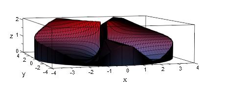
30 Figure 3.19 The 3D Plot of the Spiral Staircase. The next multivariable calculus surface we will look at is defined by the equation: z = f(x,y) = 2x 2 y/(x 4 +y 2 ). Now we can see that f is not defined at (0,0). So let s take a look at what this surface might look like. Letting y = x 2 we will see that f(x,y) is constant along the parabola because substituting x 2 for y we get the following: f(x, x 2 ) = 2x 2 (x 2 )/(x 4 +(-x 2 ) 2 ) = 2x 4 /2x 4 = 1 And if y = -x 2 then, f(x,-x 2 ) = 2x 2 (-x 2 )/(x 4 +(-x 2 ) 2 = -2x 4 /2x 4 = -1 Looking at the xy plane from above we see the following in Figure
31 Figure 3.20 xy Plane From Above. So setting the definition of f(0,0) to 0 will not make f continuous at (0,0). So as in the spiral staircase model, our code for our parabola-like model is listed in black at the top of Appendix C. The code is repeated in red and the derived values and formulas are listed in blue. Finally at the end of each section, the model part is shown in red and blue with black shading. The final MatLab.stl model is shown below in Figure
32 Figure 3.21 f(x,y) = 2x 2 y/(x 4 +y 2 ) in MatLab. As you can see, from our model in Figure 3.22, the printer did a nice job. This model is also 75 mm in diameter and stands about 19 mm high. At high resolution this model took 2 hours and 53 minutes to print. This print was made possible by manipulation of the.stl file in software called Maya. Maya is part of the AutoDesk suite of design programs. We will discuss this manipulation further in Chapter Five when we address the challenges of 3D printing. 23
33 Figure 3.22 The Multivariable Calculus Model is Complete. Our last model is designed in Autodesk Inventor using the equations function. We let x = t and y = 1/t After this curve is plotted on the xy plane, it is rotated 360 degrees around the y axis. In order for the base to be solid we had to connect the y and x axis at (.01,.01). This also takes into consideration the fact x and y never equal zero. The screen shot of this model is shown in Figure
34 Figure 3.23 y = 1/x Rotated Around the y Axis. The solid 3D model is shown in Figure One of our goals for this model is to show how the base runs off horizontally in all directions and that the y value asymptotically approaches infinity as x approaches 0. Or in this case, the base gets thinner until it is completely gone. Another goal is to see how the x value asymptotically approaches zero as the y value gets larger and larger. Or in this case, the tip gets thinner and thinner until it forms a sharp point and the printer eventually stops. 25
35 Figure 3.24 The Finished 3D Plot of y = 1/x. 26
36 CHAPTER IV PRELIMINARY MATERIAL 4.1 The Search for the Use of a 3D Printer So, now we have some mathematical models on which to focus. The next step is to figure out how best to make them. Our first exposure to a 3D printer was in Frank Anderson s classroom at the Byron Martin Technology Center (BMTC) at 34 th Street on Q Avenue. Frank teaches Computer Aided Design (CAD) for the Lubbock Independent School District (LISD). Figure 4.1 shows the early model MakerBot 3D Printer at the BMTC in LISD. 27
37 Figure 4.1 MakerBot Replicator at the BMTC in LISD. 28
38 While visiting off campus, Frank showed us a 3D model one of his students had made. He explained that there are many design softwares in existence which could be used to make models. Being a CAD instructor, he was most familiar with AutoCad. The second option we found was at the Texas Tech University Architecture School. They were willing to let us use their printer but its use would be limited. The Architecture students keep it busy most of the time. Our research revealed that there are 3D printer services available for hire. We consulted with a company called Sculpteo. They required.stl files and cash for hourly printing service fees, packing and shipping. Other resources revealed that Virginia Tech University has a 3D printer vending machine available, Virginia Tech (2014). A student plugs in their model file, swipes their credit card, and after some time, out comes the desired 3D model. Mail order and vending 3D printing are nice for those who do not have access to a 3D printer, but the same amount of software programming work is required to hire a remote vendor. We preferred to find a locally run 3D printer. So we continued to search. Our contacts with Electrical Engineering seemed even more promising. The EE Building is in close proximity to the Mathematics Building. Upon further investigation, we found that the electrical engineers have at their disposal an actual 3D printing laboratory. In TTU s EE Department, the 3D printer utilized is a MakerBot Replicator 2. Compatible software for operating the MakerBot is found at: MakerBot. (2013). Figure 4.2 shows the TTU EE MakerBot Replicator 2. 29
39 Figure 4.2 The TTU EE MakerBot Replicator 2. Later we discovered a 3D printer was available in the 3D animation Lab on the second floor of the TTU library. Figure 4.3 shows this printer. 30
40 Figure 4.3 MakerBot Replicator 2 in the 3D Animation Lab at the TTU Library. The 3D Lab Manager, Kevin Jones, gave us a tour and encouraged us to write a proposal to apply for access to the lab through Ken Chaffin, Director LTMS Public Operations: Digital Media Studio, 3D Lab, Media Lab, TTU Libraries. See Appendix A for our proposal and Ken Chaffin s approval. Lab access was granted from 7:00 a.m. to 5:00 p.m. on Monday through Friday. 4.2 Selecting the Correct Software Now that we located a 3D printer we needed to select software to design our 3D models. Many types of software are available for 3D design. Work horses like 31
41 AutoCAD, Mathmatica, and Maple were considered. All have rather steep learning curves. Through influence in Facilities Design, we tried to make Google SketchUp work. Google SketchUp is easy to learn and is free to download from the internet. As a result, we downloaded Google Sketchup and designed our first model. Google (2013). It was a perfect cube. Then we sliced it into thirds. However, the free version of Google Sketchup has no way to develop the.stl file which is necessary to drive the 3D printer. We tried adding on software modules and even considered purchasing the $600 professional version of Google Sketchup. Since it is too expensive and does not make.stl files, we abandoned this design software option. Since we are mechanical engineers by training and facility directors by trade, we have quite a lot of experience in reading design documents drawn in AutoCad. But we are from the old school of T-squares and triangles and only have experience drawing with pencil and paper. From our experience, AutoCad is an extremely involved and expensive software. AutoCad is great for making architectural plans and very detailed mechanical design drawings. New building construction and renovation plans are best suited for AutoCad. Along with these great details for facilities design comes a very steep learning curve. And since it is very expensive, we decided to continue our design software search. Our Electrical Engineering contacts recommended using Inventor by AutoDesk. Our Byron Martin Technology Center staff contacts verified that Inventor was successfully utilized by their students. We downloaded free educational versions of Inventor at the following website: Autodesk (2013). For our more complicated 3D mathematics models we considered using MatLab. We will discuss our MatLab models in more detail later in this text. 4.3 AutoDesk s Advantages AutoDesk Inventor has several advantages over other design softwares. Some important advantages are that it is free to students on the internet and it can produce.stl 32
42 files to drive our 3D printer. Inventor is an industry standard for solid model designers and has been used successfully for years. Furthermore, it has a fairly flat learning curve. Finally it can design in English or metric units. We like using metric units since all dimensions follow the base ten convention. 4.4 AutoDesk s Disadvantages AutoDesk s primary disadvantage is that it cannot easily accommodate free hand drawing. Also, Inventor uses dimensions as its main designing force, but it cannot design with one scale on the y axis and a different scale on the x axis D Model Making Next we partnered with TTU s Electrical Engineering Chair, Dr. Michael Giesselmann He introduced us to the EE 3D Printing Lab Manager, Joshua Hoose. He became our ally in EE and successfully printed out many of our.stl files. The nice thing about 3D modeling is how precise the end model is. Another advantage is the perfect repeatability. Our AutoDesk.stl files are small enough that they can be easily ed anywhere. ing our.stl files proved helpful as we coordinated with the TTU EE 3D Printing Lab. Josh printed out Book 1, Proposition 1 after several hours of drawing in AutoDesk Inventor Professional. 4.5 The Predominantly Tactile Learner Next, a blessing came in the form of a blind math graduate student. Kyle J. Steinle joined our team along with his trusty companion, Janette, a yellow lab mix service dog. Kyle lends the perfect experience of how to make tactile learning aids most useful. Kyle introduced Braille as the ultimate tactile communication aid. The Braille on our first model was too small to be read by touch. So we measured the universal Braille characters and found that they are 6.5 mm in height. We were able to convert our model labels to Braille by importing a Braille font into Microsoft Word and then into AutoDesk 33
43 Inventor. The Braille font can be downloaded from the following website.: 0Fonts&level=free Duxbury (2013). Braille textbooks can run as much as $75,000 if all text and figures are converted. We were surprised to find that a classic like Euclid s Elements has never been transcribed into Braille for blind learners. 34
44 CHAPTER V 3D PRINTING 5.1 Beginning with 3D Printing After carefully feeling preliminary 3D plots from Josh Hoose, Kyle suggested raised object outlines to allow his fingers to see the plots more clearly. This was done in the first four proposition of Euclid s Elements. He also suggested line points which are small cylinder wall tops, versus solid cylinder tops. Finally he suggested using the universal Braille Font sizes as mentioned earlier at 6.5 mm tall. Braille dot tops need to be.5 mm for the MakerBot 3D printer to print repeatable models. The goal was to provide the first several of Euclid s Book 1 Propositions with 3D images complete with Braille labels. Future research could yield models of all of Euclid s work from Euclid s Elements All Thirteen Books Complete in One Volume. Euclid (2013). The text also needs to be transcribed in Braille. This would be a very helpful study aid for future tactile learners. 5.2 Disadvantages of 3D Printing 3D printing is a very time consuming process. It takes over an hour to print a small model. In a 3D model the work horse is writing the.stl file. Writing that file can take hours by itself. The softwares involved often have a steep learning curve. Another disadvantage is the need for a 3D printer lab. Consideration should be given to purchasing a 3D printer for future developments in the Math Department. 5.3 Other Methods of Obtaining Similar Outcomes Injection molding could make the same parts. To make an injection molding tool, however, would cost at least $40,000. This tool would be made out of finely machined metal. This type of molding is used to make thousands of parts in just a few days. 35
45 Manufacturing thousands of parts is the only way to get the price per part down to a reasonable cost. Even if all 1,500 Braille using American high school students received an injection molded part, the cost per model would be about $27. A 3D printed model is only pennies of plastic material with no waste. Another way to make these 3D models is the age old materials of balsa wood and glue. This would require a lot of measuring, cutting, sanding and gluing of wooden parts. With balsa wood models, we end up with unique models every time. So, there is no consistency from model to model. As described by Fulker and Fulker a Thermoform vacuum duplicating machine which uses heat plus suction can also be used to make plastic raised surface models. Fulker and Fulker (1968). In this process, card stock paper would be placed over a frame of window screen. Then we would draw a mirror image of the diagram. We would use a sharp instrument like a nail, a pencil or an open pen to draw on the card stock paper. As the pen passed over the screen a series of raised dots would be formed on the back side of the card stock. Labels could be made with a Braille machine and glued on to the image. Then by using the Thermoform machine, we would place a thin layer of plastic over the card stock model, close the lid, heat the plastic, and suck all of air out of the space. This would yield a nice plastic form for a reasonable price. We did not choose this model making method since the screen has a very low resolution and requires free hand drawing. It would also be hard to draw in a mirror image. 5.4 How a 3D Printer Works According to Evans (2012) a 3D printer works as a Cartesian robot having stepper motors which move the plastic extruder in the x and y directions. For example, the x direction, east to west, is determined by the horizontal bar which the extruder moves on, driven by its stepper motor. The y direction is determined by a second stepper motor which moves the horizontal bar from front to back, or north to south. Finally the z 36
46 position, or up position is sometimes driven by an all thread rod with a stepper motor. All direction increments can be as small as.1 millimeter. A rule of thumb is that 3 passes of the extruder lays down approximately 1 millimeter of plastic. This presumes.3 mm per pass, which is the lowest resolution. The print bed is heated for best results and can be covered with blue painter s tape to create the smoothest surface. We did not try this method. Instead, our 3D print lab engineer, Josh Hoose, preferred designing ears or tabs at the corners which could be easily removed upon print completion. These ears are normally.5 millimeters thick and prevented the edges of the plot from curling up as they cooled. 5.5 Printer Material Characteristics Several types of materials which can be used in 3D printing. However, there are two, PLA and ABS, which have become the industry standard. ABS or Acrylonitrile Butadiene Styrene was the first material used broadly in 3D printing. It extrudes nicely at about 215 degrees Centigrade and dries rather quickly in a ventilated space. ABS performs best when the print bed is heated to about 110 degrees Centigrade. Since it has rubber in it, the resulting models are fairly flexible and it emits noxious fumes when melted. PLA or Polylactic Acid material is the other fast drying plastic that has very good characteristics. It prints well in the typical computer or 3D animation laboratories. It melts at approximately 180 degrees Centigrade and, like ABS, has a very good printing consistency at about 215 degrees Centigrade. It works well when the print bed is heated to about 50 degrees Centigrade. Being a plastic material, it is slightly less flexible than ABS. For our purposes PLA is fine and not too brittle. Probably the best reason to select PLA is that is does not give off noxious fumes. This eliminates the need for a vent hood in the lab. 37
47 Both ABS and PLA extrude and print well at about 220 degrees Centigrade when the printer extrusion head speed is 40 mm/second or slower. However, at printer head speeds upwards of 100 mm/second, the plastic material needs to be heated to about 230 degrees Centigrade. In our work, we used the printer default speed of 90 mm/second and an extruder head temperature of 230 degrees centigrade. See the temperature warning label in Figure 5.1. Looking closely, one can see the plastic thread coming out of the extruder head. Figure 5.1 The Hot Extruder Head. The PLA spool of material weighs about one kilogram and costs about $50.00 per spool. PLA also is available in a myriad of colors. See the green spool of PLA material on the back of the printer in Figure
48 Figure 5.2 Polylactic Acid Spool on the Back of the 3D Printer D Printing is an Additive Process 3D printing uses an additive process. It puts down a layer of plastic that is.1 mm to.3 mm thick on every pass of the extruder head. Then it lays down the next layer on top of the previous layer. Layer by layer it builds until the model is complete. This is different from the art of sculpting which starts with a slab of marble and the sculptor chips away until the form is complete. Sculpting s subtractive process yields a nice end product but it also produces buckets of useless marble spoils. 39
49 The additive building process is very exact and does not produce any waste material. However, it does require a base on which to build. In the case of overhanging model parts, we will need to consider scaffolding or supports which were discussed in Section Creating a Model from Geogebra The next 2D model we printed was a raised image of Proofs without Words. Nelsen (1993). Notice the slopes of the given lines as outlined in Figure 5.3. In simple terms, the slope of a line is the rise of the line divided by the run. Or, in a triangle with the base forming a right angle, the y length over the x length equals the slope of the hypotenuse. As can be seen in this proof without words, the slope a/b < c/d is obvious when looking at the steepness of the hypotenuses. And it is also easy to see that the slope (a+c)/(b+d) is a number between the slopes of a/b and c/d. Hence: a/b < (a+c)/(b+d) < c/d. This is commonly known as the mediant property. 40

50 Figure 5.3 Proof Without Words. The Mediant Property. The above figure shows the sketch which was drawn in Geogebra, a software which is free on the internet, Geogebra (2013). This sketch gives us a template to trace when copied and pasted into Inventor. A new sketch surface must be created in Inventor. Next we insert the image in the Sketch mode. We open the image and uncheck LINK on the dialogue box. Now that the image is in place, we hit escape and open the image for modification. Although this brings up a great template, it can be very easily moved out of place anytime the view is slightly moved. For this reason, we recommend designing over the Geogebra as quickly as possible and then deleting it. We found that designing in AutoDesk Inventor is typically just as efficient as importing images from Geogebra. The completed 3D model of the median property is shown below in Figure
51 Figure 5.4 The 3D Plot of the Mediant Property. 5.7 Creating a Model in AutoDesk Inventor After we have downloaded all of our necessary software, we open AutoDesk Inventor. See the startup page in Figure 5.5. We can select either English or metric units. 42
52 Figure 5.5 Inventor Start Up Page. We select the plane in which we want to design as shown in Figure 5.6. Then we begin to design the base of our model. 43
53 Figure 5.6 Selecting the Plane in Which to Design. We use a base of 120 mm x 100 mm and design ears to prevent the corners of our model from peeling up as they cool. After removing the overlap on the ears we have a nice base. The base with ears is depicted in Figure

54 Figure 5.7 Model Base with Ears. In Figure 5.8 we select the base on which to extrude. We extrude it about.5 mm thick for the ears and another.5 mm thick for the rectangular base. Figure 5.8 The Extruded Base with Ears. 45
55 Next we place our model on the Makerware print bed to check for a proper fit as seen in Figure 5.9. Figure 5.9 The Model Fits on the Print Bed. After verifying the fit we return to our model design and begin our work on Proposition 1. We place a line and draw a circle centered around one end point and passing through the other endpoint. See Figure
56 Figure 5.10 Begin Drawing the Model. Then we draw a circle around the other end point and connect the triangle where the two circles intersect as shown in Figure Figure 5.11 The Inscribed Triangle. 47
57 After our sketch is complete, we need to add some thickness to our sketch of circles and our triangle. We use the offset function to give our lines 1 mm of width as seen in Figure Figure 5.12 Adding 1 mm of Thickness to Our Sketch. Then we trim off our interior construction lines to end up with one solid figure of intertwined circles and a triangle. See Figure Our model is now ready to be extruded in the y or up direction. 48
58 Figure 5.13 The Solid Model is Ready for Extrusion. We end the part and select it for extrusion and the result is a nice model of raised figures as seen in Figure
59 Figure 5.14 The Successful Extrusion of Our Inscribed Triangle. Finally we add vertex points on our triangle and add labeling and titles in Braille on our model. See the final plot in Figure

60 Figure 5.15 Labeled Model of Proposition One. The next step is to open the.stl file in Makerware and slice it for printing. Slices can be made in.1,.2 or.3 mm increments, depending on the desired resolution. The defaults of 230 degrees Centigrade for extruder head temperature and 90 mm/second print head speed are acceptable. See the model in Makerware in Figure The file can now be saved in the.x3g format and saved on an SD disk for printing. 51
61 Figure 5.16 Model in Makerware for Slicing Into an.x3g File. After placing the.x3g file into the MakerBot Replicator 2, we are able to obtain the desired 3D plot of Euclid s Elements, Book 1, Proposition 1. See Figure 5.17 for the 3D plot. 52
62 Figure D Plot of an Equilateral Triangle. 5.7 Challenges 3D printing is not without its challenges. When we attempted to print out our multiple variable models, our 3D printer would not print a smooth model. After the base of our model was printed, the printer began to print fuzz and needed more direction. Our many attempts were both time consuming and wasteful. We tried adjusting the size and resolution of our model, to no avail. At one point the printer extruder head jammed and the filament had to be removed and re-inserted. One of our failed attempts is shown in Figure
63 Figure 5.18 The MakerBot Was Confused. We discovered that the mesh lines on the top and bottom surfaces did not line up correctly with the mesh lines on the sides of our model. To correct these errors we introduced yet another software, Maya, to line up the meshes. This was suggested by the 3D Animation Lab Manager after much thought and after many trials and errors. See the Maya blowup in Figure 5.19 where the mesh lines do not coincide. 54
64 Figure 5.19 Maya Cleaned Up the Models for 3D Printing. Maya is a free software on the internet. It can be downloaded at this website: Maya (2014). Care must be taken to download the 2014 version since older versions do not recognize the.stl file format. We deleted the mesh lines on the outside and inside of the model. Then we performed the extrusion again. This lined up the mesh lines on these sides. Finally we saved the modified model in our.stl file. 55
65 CHAPTER VI SUMMARY 6.1 Multiple Softwares Required We used at least three softwares on each of our models. In some cases we used five softwares. Geogebra makes files in.ggb format. It was used to construct geometric figures as were needed for Euclid s Elements and for the mediant property. It served as a template when designing in AutoDesk Inventor. Inventor was our second software which was used extensively in our raised 2D models. We also used Inventor while designing some of our solid models like y = 1/x and the three pyramids which made a cube. Inventor made the necessary.stl files to drive our 3D printer. MatLab was our third software used. We utilized it to make our 3D models of multivariable surfaces in space. MatLab was readily available on most computers in the TTU Mathematics building. MatLab makes mathematical programming code in.mn files, or MuPAD Notebook files. MatLab also makes files in the.stl format. AutoDesk Maya is a helpful 3D animation modeling software. It was used to insure proper mesh configuring, especially where two surfaces met. Maya makes.obj files and.stl files, the latter of which drives the 3D printer. And finally, we used Makerware for every model. Makerware is specific to the MakerBot Replicator 2. Makerware opens.stl files and slices the models to prepare them for printing. When our Makerware software makes a.x3g file that is saved on our SD disk, the disk can be directly inserted into our MakerBot Replicator 2 printer. If a different make of 3D printer is used, it will need its own specific slicing software to prepare models for printing. 56
66 6.2 Reflections on Tactile Learning Since most learners are primarily visual or auditory learners, we find that tactile models work best as a supplemental learning aid. Tactile models are particularly helpful to visually impaired students. Watching what a blind learner is touching helps us talk them through the details of what is going on with the surface. We know that models can be 2D with raised figures as is shown in Euclid s Elements and proofs without words. Models can be solid shapes as in the multivariable calculus models, the three pyramids which make a cube, and y = 1/x. Models depicting functions, and points where functions are not continuous yield great understanding to all learners We recommend using the highest resolution when printing the models. Although it will take three times as long to print, it produces a much smoother surface. It is always very helpful to have a blind consultant when building tactile models. He/She can touch them and ask questions when interpreting the intent of the model. Finally, we learned that tactile models are useful to supplement all types of learning styles. Holding a 3D model and rotating it in our hands is much more instructional than just looking at a 3D sketch on paper. 6.3 Future Work We plotted the first four of forty-eight propositions of Euclid s Elements. Completing 3D models for the remaining propositions in Euclid s Elements is a worthwhile exercise. No tactile models of the propositions exist. Blind students finally would be able to understand the geometric proofs as they are discussed. Continuing work on Braille translated text would be beneficial to supplement our 3D plotted work for blind students. We recommend starting with Euclid s Elements since no Braille transcriptions exist at this time. 57
67 Plotting other proofs without words would be most helpful. These are probably the most beneficial since they assist learning for all students. Even auditory and visual learners can get a new perspective utilizing our 3D models. This aids learning beyond what a 3D sketch can show. Cataloguing these and other files in the.stl format and placing them in an online library would be a valuable resource to any instructor with access to a 3D printer. Surveying mathematics instructors could help prioritize and guide future model making needs for tactile learners. Finally, serious consideration should be given to procuring a 3D printer for the TTU Mathematics and Statistics Department. All of this proposed future work will assist learning in multiple levels of mathematics understanding 58
68 BIBLIOGRAPHY APH. (2012). Distribution of Eligible Students Base on the Federal Quota Census of January 3, 2011 (Fiscal Year 2012) Annual Report of the American Printing House for the Blind, Inc. Retrieved from Autodesk. (2013). Autodesk Inventor. [Software]. Retrieved from Duxbury. (2013). The Braille TrueType Fonts. [Software]. Retrieved from %20Fonts&level=free. Evans, B. (2012). Practical 3D printers: The science and art of 3D printing. (e-book) Apress. Retrieved from: Euclid. (2013). Elements. D. Densmore (Ed.). Ann Arbor, MI: Sheridan Books for Green Lion Press. Fulker, W. H. and Fulker, M. (1968). Techniques with tangibles. Springfield, Illinois. Thomas Books. Geogebra. (2013). Geogebra [Software]. Available from: Google. (2013). Google Sketchup [Software]. Available from: Linkman, R. (1997). How to learn anything quickly: An accelerated program for rapid learning. Secaucus, New Jersey: Carol Publishing Group. MakerBot. (2013). MakerBot Replicator 2 User Manual, Version 4. Retrieved from Maya. (2014). AutoDesk Maya 3D Animation [Software]. Available from: Merriam Co., G. & C. (Ed.) (1977). Webster s New Collegiate Dictionary. Springfield, Massachusetts. A Merriam Webster. Nelsen, R. B. (1993). Proof without words: Exercises in visual thinking. Washington, DC: Mathematical Association of America. 59
69 Virginia Tech. (2014) Dream Vendor [Website]. Retrieved from 60
70 APPENDIX A PROPOSAL TO USE THE 3D PRINTER IN THE ANIMATION LAB 61
71 62
72 APPENDIX B MATLAB CODE FOR THE SPIRAL STAIRCASE insider:=0.2 outsider:=4 zoffset:=1.1 msh:=30 z1:=(r,u)->(2*(r*cos(u))*(r*sin(u)))/((r*cos(u))^2+(r*sin(u))^2); outside1:=plot::surface([outsider*cos(u),outsider*sin(u),z*(z1(ou tsider,u)+zoffset)],z=0..1,u=0..2*pi,mesh=[msh,msh]) plot(outside1); inside1:=plot::surface([insider*cos(u),insider*sin(u),z*(z1(insid er,u)+zoffset)],z=0..1,u=0..2*pi,mesh=[msh,msh]) plot(inside1) top1:=plot::surface([r*cos(u),r*sin(u),z1(r,u)+zoffset],r=insider..outsider,u=0..2*pi,mesh=[msh,msh]) plot(top1) bottom1:=plot::surface([r*cos(u),r*sin(u),0],r=insider..outsider, u=0..2*pi,mesh=[msh,msh]) plot(bottom1) plot(outside1,inside1,top1,bottom1) f:=notebookpath."cal3spiralstair.stl"; export::stl(f,outside1,inside1,top1,bottom1) plot(plot::surfacestl(f, MeshVisible)) 63
73 64
74 65
75 66
76 APPENDIX C MATLAB CODE FOR THE MULTIVARIABLE CALCULUS SURFACE insider:=0.2 outsider:=4 zoffset:=1.1 msh:=40 z1:=(r,u)->(2*(r*cos(u))^2*r*sin(u))/((r*cos(u))^4+(r*sin(u))^2); outside1:=plot::surface([outsider*cos(u),outsider*sin(u),z*(z1(ou tsider,u)+zoffset)],z=0..1,u=0..2*pi,mesh=[msh,msh]) plot(outside1); inside1:=plot::surface([insider*cos(u),insider*sin(u),z*(z1(insid er,u)+zoffset)],z=0..1,u=0..2*pi,mesh=[msh,msh]) plot(inside1) top1:=plot::surface([r*cos(u),r*sin(u),z1(r,u)+zoffset],r=insider..outsider,u=0..2*pi,mesh=[msh,msh]) plot(top1) bottom1:=plot::surface([r*cos(u),r*sin(u),0],r=insider..outsider, u=0..2*pi,mesh=[msh,msh]) plot(bottom1) plot(outside1,inside1,top1,bottom1) f:=notebookpath."cal3parabola.stl"; export::stl(f,outside1,inside1,top1,bottom1) plot(plot::surfacestl(f, MeshVisible)) 67
77 68
78 69

79 70
Geometry and Measurement
 The student will be able to: Geometry and Measurement 1. Demonstrate an understanding of the principles of geometry and measurement and operations using measurements Use the US system of measurement for
An Application of Analytic Geometry to Designing Machine Parts--and Dresses
 Electronic Proceedings of Undergraduate Mathematics Day, Vol. 3 (008), No. 5 An Application of Analytic Geometry to Designing Machine Parts--and Dresses Karl Hess Sinclair Community College Dayton, OH
Technical Drawing Specifications Resource A guide to support VCE Visual Communication Design study design 2013-17
 A guide to support VCE Visual Communication Design study design 2013-17 1 Contents INTRODUCTION The Australian Standards (AS) Key knowledge and skills THREE-DIMENSIONAL DRAWING PARALINE DRAWING Isometric
Creating Smart Models From Scan Data
 Rapidform Tech Tip Creating Smart Models From Scan Data Related Product Version Rapidform XOR3 Goal To create a smart model from scan data. A smart model is a parametric model that uses parameters intelligently
SketchUp Instructions
 SketchUp Instructions Every architect needs to know how to use SketchUp! SketchUp is free from Google just Google it and download to your computer. You can do just about anything with it, but it is especially
Introduction to Autodesk Inventor for F1 in Schools
 Introduction to Autodesk Inventor for F1 in Schools F1 in Schools Race Car In this course you will be introduced to Autodesk Inventor, which is the centerpiece of Autodesk s digital prototyping strategy
TABLE OF CONTENTS. INTRODUCTION... 5 Advance Concrete... 5 Where to find information?... 6 INSTALLATION... 7 STARTING ADVANCE CONCRETE...
 Starting Guide TABLE OF CONTENTS INTRODUCTION... 5 Advance Concrete... 5 Where to find information?... 6 INSTALLATION... 7 STARTING ADVANCE CONCRETE... 7 ADVANCE CONCRETE USER INTERFACE... 7 Other important
An introduction to 3D draughting & solid modelling using AutoCAD
 An introduction to 3D draughting & solid modelling using AutoCAD Faculty of Technology University of Plymouth Drake Circus Plymouth PL4 8AA These notes are to be used in conjunction with the AutoCAD software
3D Printing LESSON PLAN PHYSICS 8,11: OPTICS
 INVESTIGATE RATIONALE Optics is commonly taught through the use of commercial optics kits that usually include a basic set of 2-4 geometric lenses (such as double convex or double concave). These lenses
ClarisWorks 5.0. Graphics
 ClarisWorks 5.0 Graphics Level 1 Training Guide DRAFT Instructional Technology Page 1 Table of Contents Objectives... Page 3 Course Description and Organization... Page 4 Technology Requirements... Page
MD5-26 Stacking Blocks Pages 115 116
 MD5-26 Stacking Blocks Pages 115 116 STANDARDS 5.MD.C.4 Goals Students will find the number of cubes in a rectangular stack and develop the formula length width height for the number of cubes in a stack.
SolidWorks. SolidWorks Teacher Guide. and Student Courseware
 SolidWorks SolidWorks Teacher Guide and Student Courseware SolidWorks Corporation Outside the U.S.: +1-978-371-5011 300 Baker Avenue Fax: +1-978-371-7303 Concord, Massachusetts 01742 USA Email: info@solidworks.com
3D Printing Design Guidelines Sierra College CACT
 3D Printing Design Guidelines Sierra College CACT Prepared by ARW Consulting June 30, 2009 Table of Contents Scope of this Document.. 1 General Overview... 2 File Format.. 3 SST Support Material.. 4 Venting
VISUAL ALGEBRA FOR COLLEGE STUDENTS. Laurie J. Burton Western Oregon University
 VISUAL ALGEBRA FOR COLLEGE STUDENTS Laurie J. Burton Western Oregon University VISUAL ALGEBRA FOR COLLEGE STUDENTS TABLE OF CONTENTS Welcome and Introduction 1 Chapter 1: INTEGERS AND INTEGER OPERATIONS
Warning! Construction Zone: Building Solids from Nets
 Brief Overview: Warning! Construction Zone: Building Solids from Nets In this unit the students will be examining and defining attributes of solids and their nets. The students will be expected to have
Cura for Type A Machines Quick Start Guide
 Cura for Type A Machines Quick Start Guide 1 Table of Contents About Cura for Type A Machines Downloading Cura for Type A Machines Installing Cura for Type A Machines Mac Windows Linux About the Configuration
Discovering Math: Exploring Geometry Teacher s Guide
 Teacher s Guide Grade Level: 6 8 Curriculum Focus: Mathematics Lesson Duration: Three class periods Program Description Discovering Math: Exploring Geometry From methods of geometric construction and threedimensional
SpaceClaim Introduction Training Session. A SpaceClaim Support Document
 SpaceClaim Introduction Training Session A SpaceClaim Support Document In this class we will walk through the basic tools used to create and modify models in SpaceClaim. Introduction We will focus on:
Introduction to Autodesk Inventor for F1 in Schools
 F1 in Schools race car Introduction to Autodesk Inventor for F1 in Schools In this course you will be introduced to Autodesk Inventor, which is the centerpiece of Autodesk s Digital Prototyping strategy
Microsoft Excel 2010 Charts and Graphs
 Microsoft Excel 2010 Charts and Graphs Email: training@health.ufl.edu Web Page: http://training.health.ufl.edu Microsoft Excel 2010: Charts and Graphs 2.0 hours Topics include data groupings; creating
MAKERBOT DESKTOP. All instructions in this tutorial are for use with a Flashforge Creator X (replicator single) using Makerbot Desktop.
 using Makerbot Desktop.") MAKERBOT DESKTOP All instructions in this tutorial are for use with a Flashforge Creator X (replicator single) using Makerbot Desktop. Download Software Download software fromhttps://www.makerbot.com/desktop
MAKERBOT DESKTOP All instructions in this tutorial are for use with a Flashforge Creator X (replicator single) using Makerbot Desktop. Download Software Download software fromhttps://www.makerbot.com/desktop
Angles that are between parallel lines, but on opposite sides of a transversal.
 GLOSSARY Appendix A Appendix A: Glossary Acute Angle An angle that measures less than 90. Acute Triangle Alternate Angles A triangle that has three acute angles. Angles that are between parallel lines,
If A is divided by B the result is 2/3. If B is divided by C the result is 4/7. What is the result if A is divided by C?
 Problem 3 If A is divided by B the result is 2/3. If B is divided by C the result is 4/7. What is the result if A is divided by C? Suggested Questions to ask students about Problem 3 The key to this question
GeoGebra. 10 lessons. Gerrit Stols
 GeoGebra in 10 lessons Gerrit Stols Acknowledgements GeoGebra is dynamic mathematics open source (free) software for learning and teaching mathematics in schools. It was developed by Markus Hohenwarter
12-1 Representations of Three-Dimensional Figures
 Connect the dots on the isometric dot paper to represent the edges of the solid. Shade the tops of 12-1 Representations of Three-Dimensional Figures Use isometric dot paper to sketch each prism. 1. triangular
Algebra Geometry Glossary. 90 angle
 lgebra Geometry Glossary 1) acute angle an angle less than 90 acute angle 90 angle 2) acute triangle a triangle where all angles are less than 90 3) adjacent angles angles that share a common leg Example:
Laser Cutter User Manual
 Laser Cutter User Manual frequently asked questions... the laser is cutting weird! it s cutting a thick line or not cutting through at all! Table Of Contents Section 1: Materials Guide 1.1 Can I Cut this?
10. THERM DRAWING TIPS
 10. THERM DRAWING TIPS 10.1. Drawing Tips The THERM User's Manual describes in detail how to draw cross-sections in THERM. This section of the NFRC Simualation Training Manual presents some additional
USING ALGEBRA TILES EFFECTIVELY
 MATHEMATICS USING ALGEBRA TILES EFFECTIVELY TOOLS FOR UNDERSTANDING by Bettye C. Hall Reviewers James Gates, Ed.D. Yvonne S. Gentzler, Ph.D. AUTHOR Bettye C. Hall is the former Director of Mathematics
Classroom Tips and Techniques: The Student Precalculus Package - Commands and Tutors. Content of the Precalculus Subpackage
 Classroom Tips and Techniques: The Student Precalculus Package - Commands and Tutors Robert J. Lopez Emeritus Professor of Mathematics and Maple Fellow Maplesoft This article provides a systematic exposition
MATHEMATICS FOR ENGINEERING BASIC ALGEBRA
 MATHEMATICS FOR ENGINEERING BASIC ALGEBRA TUTORIAL 4 AREAS AND VOLUMES This is the one of a series of basic tutorials in mathematics aimed at beginners or anyone wanting to refresh themselves on fundamentals.
Kristen Kachurek. Circumference, Perimeter, and Area Grades 7-10 5 Day lesson plan. Technology and Manipulatives used:
 Kristen Kachurek Circumference, Perimeter, and Area Grades 7-10 5 Day lesson plan Technology and Manipulatives used: TI-83 Plus calculator Area Form application (for TI-83 Plus calculator) Login application
What s New V 11. Preferences: Parameters: Layout/ Modifications: Reverse mouse scroll wheel zoom direction
 What s New V 11 Preferences: Reverse mouse scroll wheel zoom direction Assign mouse scroll wheel Middle Button as Fine tune Pricing Method (Manufacturing/Design) Display- Display Long Name Parameters:
Math 0980 Chapter Objectives. Chapter 1: Introduction to Algebra: The Integers.
 Math 0980 Chapter Objectives Chapter 1: Introduction to Algebra: The Integers. 1. Identify the place value of a digit. 2. Write a number in words or digits. 3. Write positive and negative numbers used
0 Introduction to Data Analysis Using an Excel Spreadsheet
 Experiment 0 Introduction to Data Analysis Using an Excel Spreadsheet I. Purpose The purpose of this introductory lab is to teach you a few basic things about how to use an EXCEL 2010 spreadsheet to do
Solving Simultaneous Equations and Matrices
 Solving Simultaneous Equations and Matrices The following represents a systematic investigation for the steps used to solve two simultaneous linear equations in two unknowns. The motivation for considering
NEW MEXICO Grade 6 MATHEMATICS STANDARDS
 PROCESS STANDARDS To help New Mexico students achieve the Content Standards enumerated below, teachers are encouraged to base instruction on the following Process Standards: Problem Solving Build new mathematical
Derive 5: The Easiest... Just Got Better!
 Liverpool John Moores University, 1-15 July 000 Derive 5: The Easiest... Just Got Better! Michel Beaudin École de Technologie Supérieure, Canada Email; mbeaudin@seg.etsmtl.ca 1. Introduction Engineering
Parallel Plate Capacitor
 Parallel Plate Capacitor Capacitor Charge, Plate Separation, and Voltage A capacitor is used to store electric charge. The more voltage (electrical pressure) you apply to the capacitor, the more charge
The Notebook Software Activity Guide
 The Notebook Software Activity Guide The Notebook software activity guide is intended to act as a reference of the best practices for creating and presenting lesson activities using Notebook software.
Gas Dynamics Prof. T. M. Muruganandam Department of Aerospace Engineering Indian Institute of Technology, Madras. Module No - 12 Lecture No - 25
 (Refer Slide Time: 00:22) Gas Dynamics Prof. T. M. Muruganandam Department of Aerospace Engineering Indian Institute of Technology, Madras Module No - 12 Lecture No - 25 Prandtl-Meyer Function, Numerical
Etch Drawing Preparation
 Etch Drawing Preparation Introduction Most etching companies prefer you to supply the drawing for your design in the form of a computer file. While some will still accept drawn or printed artwork, it is
SAT Subject Test Practice Test II: Math Level II Time 60 minutes, 50 Questions
 SAT Subject Test Practice Test II: Math Level II Time 60 minutes, 50 Questions All questions in the Math Level 1 and Math Level Tests are multiple-choice questions in which you are asked to choose the
Section 1.1. Introduction to R n
 The Calculus of Functions of Several Variables Section. Introduction to R n Calculus is the study of functional relationships and how related quantities change with each other. In your first exposure to
Getting Started in Tinkercad
 Getting Started in Tinkercad By Bonnie Roskes, 3DVinci Tinkercad is a fun, easy to use, web-based 3D design application. You don t need any design experience - Tinkercad can be used by anyone. In fact,
The Fourth International DERIVE-TI92/89 Conference Liverpool, U.K., 12-15 July 2000. Derive 5: The Easiest... Just Got Better!
 The Fourth International DERIVE-TI9/89 Conference Liverpool, U.K., -5 July 000 Derive 5: The Easiest... Just Got Better! Michel Beaudin École de technologie supérieure 00, rue Notre-Dame Ouest Montréal
Basic 2D Design Be sure you have the latest information!
 Basic 2D Design mastercam x getting started tutorials Basic 2D Design December 2011 Be sure you have the latest information! Information might have been changed or added since this document was published.
My Custom Design ver.1.0
 My Custom Design ver.1.0 Embroidery Data Creation Software Instruction Manual Before using this software, be sure to read this Instruction Manual for information on the correct use of the software. Keep
Designing and Drawing a Sprocket Visualizing ideas through the creation of CAD solid models is a key engineering skill.
 05 Webster St. Hanover Massachusetts 0339 Tel. 78 878 5 Fax 78 878 6708 Designing and Drawing a Sprocket Visualizing ideas through the creation of CAD solid models is a key engineering skill. The following
Intro to Excel spreadsheets
 Intro to Excel spreadsheets What are the objectives of this document? The objectives of document are: 1. Familiarize you with what a spreadsheet is, how it works, and what its capabilities are; 2. Using
Reflection and Refraction
 Equipment Reflection and Refraction Acrylic block set, plane-concave-convex universal mirror, cork board, cork board stand, pins, flashlight, protractor, ruler, mirror worksheet, rectangular block worksheet,
Common Core Unit Summary Grades 6 to 8
 Common Core Unit Summary Grades 6 to 8 Grade 8: Unit 1: Congruence and Similarity- 8G1-8G5 rotations reflections and translations,( RRT=congruence) understand congruence of 2 d figures after RRT Dilations
GEOMETRY. Constructions OBJECTIVE #: G.CO.12
 GEOMETRY Constructions OBJECTIVE #: G.CO.12 OBJECTIVE Make formal geometric constructions with a variety of tools and methods (compass and straightedge, string, reflective devices, paper folding, dynamic
Science Notebooks in the Classroom. Notebook Criteria
 presentapresents Presents Science Notebooks in the Classroom kdkrifr Notebook Criteria This document was developed by Bay Area Schools for Excellence in Education (BASEE) a local systemic change project
Graphic Design. Background: The part of an artwork that appears to be farthest from the viewer, or in the distance of the scene.
 Graphic Design Active Layer- When you create multi layers for your images the active layer, or the only one that will be affected by your actions, is the one with a blue background in your layers palette.
SEGMENTED WOODTURNING
 Notes on: SEGMENTED WOODTURNING Malcolm Tibbetts www.tahoeturner.com malcolm@tahoeturner.com (530) 541-6135 MATHEMATICAL FORMULAS AND CONCEPTS: A circle contains 360 Circumference = Diameter x π(3.1416)
How To Solve Factoring Problems
 05-W4801-AM1.qxd 8/19/08 8:45 PM Page 241 Factoring, Solving Equations, and Problem Solving 5 5.1 Factoring by Using the Distributive Property 5.2 Factoring the Difference of Two Squares 5.3 Factoring
Autodesk Fusion 360 Badge Guide: Design an F1 in Schools Trophy
 Autodesk Fusion 360 Badge Guide: Design an F1 in Schools Trophy Abstract: Gain basic understanding of creating 3D models in Fusion 360 by designing an F1 in Schools trophy. This badge may be claimed by
YouthQuest Quick Key FOB Project
 YouthQuest Quick Key FOB Project This project is designed to demonstrate how to use the 3D design application, Moment of inspiration, to create a custom key fob for printing on the Cube3 3D printer. Downloading
SMART Board Tips & Tricks (version 9.0) Getting Started. SMART Tools vs. SMART Notebook software
 Getting Started. SMART Tools vs. SMART Notebook software") SMART Board Tips & Tricks (version 9.0) Getting Started SMART Tools vs. SMART Notebook software Click the SMART Board icon (in the system tray at the bottom right of your screen) to access the SMART Board
SMART Board Tips & Tricks (version 9.0) Getting Started SMART Tools vs. SMART Notebook software Click the SMART Board icon (in the system tray at the bottom right of your screen) to access the SMART Board
2013 Getting Started Guide
 2013 Getting Started Guide The contents of this guide and accompanying exercises were originally created by Nemetschek Vectorworks, Inc. Vectorworks Fundamentals Getting Started Guide Created using: Vectorworks
BENEFITS OF 3D PRINTING VACUUM FORM MOLDS
 WHITE PAPER BENEFITS OF 3D PRINTING VACUUM FORM MOLDS AUTHORS COLE HARTMAN (MECHANICAL ENGINEER) & VERONICA DE LA ROSA (INDUSTRIAL DESIGNER) FATHOM is driven by advanced technologies. We leverage our expertise
Lesson #13 Congruence, Symmetry and Transformations: Translations, Reflections, and Rotations
 Math Buddies -Grade 4 13-1 Lesson #13 Congruence, Symmetry and Transformations: Translations, Reflections, and Rotations Goal: Identify congruent and noncongruent figures Recognize the congruence of plane
Grade 7 & 8 Math Circles Circles, Circles, Circles March 19/20, 2013
 Faculty of Mathematics Waterloo, Ontario N2L 3G Introduction Grade 7 & 8 Math Circles Circles, Circles, Circles March 9/20, 203 The circle is a very important shape. In fact of all shapes, the circle is
What You ll Learn. Why It s Important
 These students are setting up a tent. How do the students know how to set up the tent? How is the shape of the tent created? How could students find the amount of material needed to make the tent? Why
CAD and Drawing Style Procedure
 CAD and Drawing Style Procedure 0.1.1.8 Rev. 4 Date: 2014-Nov-20 Copyright 2014, Canadian Light Source Inc. This document is the property of Canadian Light Source Inc. (CLSI). No exploitation or transfer
Motion Graphs. It is said that a picture is worth a thousand words. The same can be said for a graph.
 Motion Graphs It is said that a picture is worth a thousand words. The same can be said for a graph. Once you learn to read the graphs of the motion of objects, you can tell at a glance if the object in
3D Drawing. Single Point Perspective with Diminishing Spaces
 3D Drawing Single Point Perspective with Diminishing Spaces The following document helps describe the basic process for generating a 3D representation of a simple 2D plan. For this exercise we will be
3D Print Link's Hylian Shield
 3D Print Link's Hylian Shield Created by Ruiz Brothers Last updated on 2015-07-14 04:20:12 PM EDT Guide Contents Guide Contents Overview Parts, Tool & Supplies 3D Printing 3D Printed Parts Slicer Settings
Understand the Sketcher workbench of CATIA V5.
 Chapter 1 Drawing Sketches in Learning Objectives the Sketcher Workbench-I After completing this chapter you will be able to: Understand the Sketcher workbench of CATIA V5. Start a new file in the Part
7. 080207a, P.I. A.A.17
 Math A Regents Exam 080 Page 1 1. 08001a, P.I. A.A.6 On a map, 1 centimeter represents 40 kilometers. How many kilometers are represented by 8 centimeters? [A] 48 [B] 30 [C] 5 [D] 80. 0800a, P.I. G.G.38
Printrbot Getting Started Guide. For models: Printrbot Plus (v2) Printrbot LC (v2) Printrbot jr
 Printrbot LC (v2) Printrbot jr") Printrbot Getting Started Guide For models: Printrbot Plus (v2) Printrbot LC (v2) Printrbot jr Contents 4 Chapter 1: Welcome 4 Overview 4 Support 5 Chapter 2: Your Printrbot has arrived... now what? 5
Printrbot Getting Started Guide For models: Printrbot Plus (v2) Printrbot LC (v2) Printrbot jr Contents 4 Chapter 1: Welcome 4 Overview 4 Support 5 Chapter 2: Your Printrbot has arrived... now what? 5
Mastercam Instructions. KTH School of Architecture Digital Fabrication Lab - CNC Router Version 2.1 2014-02-06
 Mastercam Instructions KTH School of Architecture Digital Fabrication Lab - CNC Router Version 2.1 2014-02-06 CONTENTS: 1. Setup in Rhino and Mastercam 2. Creating A Drilling Operation 3. Creating A Contour
Plotting: Customizing the Graph
 Plotting: Customizing the Graph Data Plots: General Tips Making a Data Plot Active Within a graph layer, only one data plot can be active. A data plot must be set active before you can use the Data Selector
Quickstart for Desktop Version
 Quickstart for Desktop Version What is GeoGebra? Dynamic Mathematics Software in one easy-to-use package For learning and teaching at all levels of education Joins interactive 2D and 3D geometry, algebra,
Geometry Solve real life and mathematical problems involving angle measure, area, surface area and volume.
 Performance Assessment Task Pizza Crusts Grade 7 This task challenges a student to calculate area and perimeters of squares and rectangles and find circumference and area of a circle. Students must find
It is vital that you understand the rationale behind the correct answer(s) as wel as the incorrect answer options.
 as wel as the incorrect answer options.") Getting the Most out of ATI www.atitesting.com What is ATI? ATI is an online resource that will be used throughout the nursing program to help you learn about nursing practice as well as help prepare you
Getting the Most out of ATI www.atitesting.com What is ATI? ATI is an online resource that will be used throughout the nursing program to help you learn about nursing practice as well as help prepare you
The University of the State of New York REGENTS HIGH SCHOOL EXAMINATION GEOMETRY. Student Name:
 GEOMETRY The University of the State of New York REGENTS HIGH SCHOOL EXAMINATION GEOMETRY Thursday, June 17, 2010 1:15 to 4:15 p.m., only Student Name: School Name: Print your name and the name of your
Fireworks CS4 Tutorial Part 1: Intro
 Fireworks CS4 Tutorial Part 1: Intro This Adobe Fireworks CS4 Tutorial will help you familiarize yourself with this image editing software and help you create a layout for a website. Fireworks CS4 is the
Mathematics Geometry Unit 1 (SAMPLE)
") Review the Geometry sample year-long scope and sequence associated with this unit plan. Mathematics Possible time frame: Unit 1: Introduction to Geometric Concepts, Construction, and Proof 14 days This
Review the Geometry sample year-long scope and sequence associated with this unit plan. Mathematics Possible time frame: Unit 1: Introduction to Geometric Concepts, Construction, and Proof 14 days This
Printrbot Getting Started Guide. For models: Simple
 Printrbot Getting Started Guide For models: Simple Contents 4 4 4 5 5 5 6 6 6 6 7 8 Chapter 1: Welcome Overview Support Chapter 2: Your Printrbot has arrived... now what? Printrbot Kits Pre-Assembled Printrbots
WPI Rapid Prototype Guidelines --Read entire document before submitting an order--
 WPI Rapid Prototype Guidelines --Read entire document before submitting an order-- It will be assumed that you have read these guidelines. If you do not follow the guidelines during submission, you will
Star and convex regular polyhedra by Origami.
 Star and convex regular polyhedra by Origami. Build polyhedra by Origami.] Marcel Morales Alice Morales 2009 E D I T I O N M O R A L E S Polyhedron by Origami I) Table of convex regular Polyhedra... 4
Guide To Creating Academic Posters Using Microsoft PowerPoint 2010
 Guide To Creating Academic Posters Using Microsoft PowerPoint 2010 INFORMATION SERVICES Version 3.0 July 2011 Table of Contents Section 1 - Introduction... 1 Section 2 - Initial Preparation... 2 2.1 Overall
Ampere's Law. Introduction. times the current enclosed in that loop: Ampere's Law states that the line integral of B and dl over a closed path is 0
 1 Ampere's Law Purpose: To investigate Ampere's Law by measuring how magnetic field varies over a closed path; to examine how magnetic field depends upon current. Apparatus: Solenoid and path integral
EDEXCEL FUNCTIONAL SKILLS PILOT TEACHER S NOTES. Maths Level 2. Chapter 5. Shape and space
 Shape and space 5 EDEXCEL FUNCTIONAL SKILLS PILOT TEACHER S NOTES Maths Level 2 Chapter 5 Shape and space SECTION H 1 Perimeter 2 Area 3 Volume 4 2-D Representations of 3-D Objects 5 Remember what you
The University of the State of New York REGENTS HIGH SCHOOL EXAMINATION GEOMETRY. Thursday, January 24, 2013 9:15 a.m. to 12:15 p.m.
 GEOMETRY The University of the State of New York REGENTS HIGH SCHOOL EXAMINATION GEOMETRY Thursday, January 24, 2013 9:15 a.m. to 12:15 p.m., only Student Name: School Name: The possession or use of any
How to build text and objects in the Titler
 How to build text and objects in the Titler You can use the Titler in Adobe Premiere Pro to create text and geometric objects. There are three methods for creating text, each capable of producing either
Vocabulary Cards and Word Walls Revised: June 29, 2011
 Vocabulary Cards and Word Walls Revised: June 29, 2011 Important Notes for Teachers: The vocabulary cards in this file match the Common Core, the math curriculum adopted by the Utah State Board of Education,
TRIGONOMETRY FOR ANIMATION
 TRIGONOMETRY FOR ANIMATION What is Trigonometry? Trigonometry is basically the study of triangles and the relationship of their sides and angles. For example, if you take any triangle and make one of the
Blender Notes. Introduction to Digital Modelling and Animation in Design Blender Tutorial - week 9 The Game Engine
 Blender Notes Introduction to Digital Modelling and Animation in Design Blender Tutorial - week 9 The Game Engine The Blender Game Engine This week we will have an introduction to the Game Engine build
Tutorial 2: Using Excel in Data Analysis
 Tutorial 2: Using Excel in Data Analysis This tutorial guide addresses several issues particularly relevant in the context of the level 1 Physics lab sessions at Durham: organising your work sheet neatly,
Area of Parallelograms, Triangles, and Trapezoids (pages 314 318)
") Area of Parallelograms, Triangles, and Trapezoids (pages 34 38) Any side of a parallelogram or triangle can be used as a base. The altitude of a parallelogram is a line segment perpendicular to the base
Area of Parallelograms, Triangles, and Trapezoids (pages 34 38) Any side of a parallelogram or triangle can be used as a base. The altitude of a parallelogram is a line segment perpendicular to the base
It's Cool: The Shape of Change
 It's Cool: The hape of Change The text of Lesson 4: It's Cool From the books The hape of Change and The hape of Change: tocks and Flows By Rob Quaden and Alan Ticotsky With Debra Lyneis Illustrated by
Raising the Roof Creating Roofs in Revit David Cohn
 David Cohn AB322-1 Roofs are one of the most complex architectural elements to model, but with Revit you can create just about any type of roof. This class will explore the best methods for creating various
Review of Fundamental Mathematics
 Review of Fundamental Mathematics As explained in the Preface and in Chapter 1 of your textbook, managerial economics applies microeconomic theory to business decision making. The decision-making tools
West Sound Technical Skills Center 101 National Avenue N. Bremerton WA 98312
 West Sound Technical Skills Center 101 National Avenue N. Bremerton WA 98312 Instructor: Tony Sharpe Phone: 360-473-0585 Fax: 360-478-5090 Email: tony.sharpe@bremertonschools.org Hours: 7:30 a.m. 3:00
INJECTION MOLDING COOLING TIME REDUCTION AND THERMAL STRESS ANALYSIS
 INJECTION MOLDING COOLING TIME REDUCTION AND THERMAL STRESS ANALYSIS Tom Kimerling University of Massachusetts, Amherst MIE 605 Finite Element Analysis Spring 2002 ABSTRACT A FEA transient thermal structural
ID@GT prepared by Gabe Landes for T. Purdy 2009
 Rapid prototyping is the automatic construction of physical objects using solid freeform fabrication. The first techniques for rapid prototyping became available in the late 1980s and were used to produce
The University of the State of New York REGENTS HIGH SCHOOL EXAMINATION MATHEMATICS A. Tuesday, August 13, 2002 8:30 to 11:30 a.m.
 The University of the State of New York REGENTS HIGH SCHOOL EXAMINATION MATHEMATICS A Tuesday, August 13, 2002 8:30 to 11:30 a.m., only Print Your Name: Print Your School s Name: Print your name and the