E46 IHKA Control Panel Fresh Air Micro Filter Temperature Regulation - Heating Temperature Regulation - Cooling...
|
|
|
- Asher Rogers
- 8 years ago
- Views:
Transcription
1 Table of Contents E46 CLIMATE CONTROL Subject Page E46 IHKA Control Panel Fresh Air Micro Filter Temperature Regulation - Heating Temperature Regulation - Cooling Compressor Control Stepper Motor M-Bus Control Convertible Rear Window Defroster IHKA Personalization System Operation Diagnosis and Troubleshooting E46 IHKA I.P.O Solar Sensor Purpose of the System Solar Radiation Solar Sensor Components System Operation Initial Print Date:10/30/00 Revision Date:12/05/00

2 Subject Page Control Curves Blower Intervention Temperature Intervention Ventilation Intervention Diagnosis Workshop Hints E46 IHKR Purpose of the System System Components IHKR I.P.O IHKR Control Unit IHKR Housing Principle of operation Blower adjustment Air Distribution Temperature Control Engine Map Cooling Service Station Feature Air Conditioning Control Air Intake Ram Effect Air Compensation Rear Window Defroster Workshop Hints Review Questions

3 E46 IHKA Model: E46 Production Date: From 6/98 Objectives After completing this module you should be able to: Know how to replace the Fresh Air Micro Filter. Describe the climate control functions performed by the IHKA control unit. Explain the compressor activation circuit. Recognize Car and Key Memory programming possibilities. 3

4 E46 IHKA Climate Control The IHKA heater/air conditioner in the E46 is similar to the system previously installed in the E36. Design and component changes were made to improve the overall performance and operation of the system. This module will deal with the changes and highlights of the E46 IHKA system. Features of the IHKA system include: Control Panel/Module Single heater core for temperature regulation M-Bus Control of all stepper motors Fresh air micro filter Regulated A/C compressor Regulated auxiliary fan operation Heater Control Personalization A CONTROL PANEL All heating and air conditioning functions are carried out at the control panel. The panel is constructed as follows: The three manual air distribution buttons are located on the left side of the panel for upface vent and footwell distribution. The automatic air distribution button is located on the bottom of the panel along with the temperature control - blower speed control and recirculation control buttons. The defrost, air conditions request and rear window defogger buttons are located on the right side of the panel. The LCD matrix displays the requested temperature setting and blower speeds as on the previous system. There is now only one setting for temperature control. The interior temperature sensor and blower fan are located on the left side of the LCD matrix. 4

5 FRESH AIR MICRO FILTER The fresh air micro filter is installed in the fresh air inlet of the engine compartment. The filter can be serviced quickly by removing the plastic cover and removing the filter. 5

6 TEMPERATURE REGULATION-HEATING The E46 uses one water valve/heater core as part of interior temperature regulation. The water valve is pulsed to control the flow of coolant through the heater core as on other systems. Temperature regulation is based on the inputs from: Temperature control switch Interior temperature sensor Ambient temperature signal Heater core sensor Evaporator temperature signal "Y" factor The rocker switch is used to select the desired cabin temperature which is displayed in the matrix of the control panel. The range for temperature display is from 60 to 90 F. SERVICE STATION FEATURE - The "Service Station" feature introduced with the E38 IHKA is integrated into the E46 IHKA. This prevents the heater core from being flooded with hot coolant when refueling the vehicle. 6

7 TEMPERATURE REGULATION - COOLING Air conditioning control on the E46 is similar to the E39 IHKA system. The system uses the variable displacement compressor. The swash plate of the compressor is hinged so that is can vary the piston travel based on the output requirements of the system. AUX. FAN MS42.0 COMPRESSOR A EVAPORATOR PRESSURE SENSOR 7

8 COMPRESSOR CONTROL Control of the A/C compressor is a function of the Engine Control Module as in the E36. However, the control has changed to include the regulated auxiliary fan operation. Pressing the snowflake button is a request for A/C activation. As long as the evaporator temperature is Above 36 F, the IHKA will signal the DME control module to activate the compressor. The IHKA control module sends the following signals to the DME over the K-Bus and CAN Bus via the instrument cluster: Request for A/C activation (signal KO) Load torque for switching the compressor on Requested auxiliary fan speed The IHKA determines the load torque for compressor activation and required auxiliary fan speed from the pressure sensor mounted on the receiver/dryer. The pressure sensor provides a linear voltage input signal (0-5 volts) to the IHKA control module. The IHKA processes this signal and determines the load torque of the system (0 to 30 Nm with a variable displacement compressor). The higher the pressure in the system, the higher the voltage input signal to the IHKA. The output signal to the DME will enable the engine control module to modify the idle speed, timing and fuel injection amount based on the load that will be imposed when the compressor is activated. The auxiliary fan is now a variable speed fan (15 stages) based on the system load. The DME will activate the fan through a pulse modulated final stage control. 8

9 STEPPER MOTOR M-BUS CONTROL The E46 uses the M-Bus for stepper motor control. All five stepper motors of the IHKA are bus controlled including: Two fresh air/recirc-air flap motors Face vent flap motor Footwell flap motor Defrost flap motor Due to the requirement for a fast acting motor for the fresh/recirc flaps, two different stepper motors (slow/fast) are used in the system. 9
 are used")
10 CONVERTIBLE REAR WINDOW DEFROSTER Purpose of the System: A two relay system was designed for the E46iC that supplies power to either rear window defogger grid. The two relay system will also communicates with the audio system amplifier to change the dynamics of the sound for either top up/hard top installed or top down driving Components of the System: Two relays, located on the right side rear quarter panel behind the interior trim cover, are used for rear defroster operation. Relay K-13 receives KL 30 and the activa tion signal from the IHKA control module. The output from the relay will switch the rear defroster ON if the hard top is installed. Relay K-99 receives KL 30 from relay K-13 and it supplies the rear defogger grid in the soft top glass window when the top is raised. 10

11 System Operation The rear defroster operation is a function of the IHKA system, with the control module responsible for switching the system ON/OFF. Two rear defrosted grids are used, one installed in the soft top rear glass and the other in the optional hard top rear glass. When the button is pressed on the IHKA control panel, Relay K-13 is energized. If the hard top is installed, power is supplied to the grid through the connector strip on the hard top lock. CVM Top Closed and locked to frame. 12V Open and unlocked. 0V Audio Amp. To hard top rear window contact. K-13 Rear window defogger relay (for hard top). K-99 Rear window defogger relay. IHKA Control Unit 31 Rear window defroster grid KL 31 61E46DEFROSTER0200 Relay K-13 also supplies KL 30 to relay K-99 when the button is pressed on the IHKA control panel. Relay K-99 is energized when KL R is switched ON and the soft top is closed and locked to the windshield frame. This allows the grid in the soft top window to be heated. When the soft top is lowered, KL R to relay K-99 is interrupted by the CVM to prevent the grid from heating when the top is lowered into the storage compartment. 11
. K-99 Rear window defogger relay.")
12 UNLEADED GASOLINE ONLY km/h A IHKA PERSONALIZATION The features of Car/Key Memory allow various functions/features of the IHKA control to be tailored to the individual owner's/driver's wishes. The functions of the IHKA that can be programmed to the owner's/driver's wishes include: Automatic activation of recirc when the vehicle is started Adjustment (raising/lowering) of the blower speed Automatic opening of the ventilation flaps with warm coolant Automatic closing of the footwell flap with A/C activation Automatic closing of the defroster flaps with A/C activation Correction of the set temperature (raise/lower) Automatic activation of the compressor control when the ignition is switched on Auto program for the blower control when the ignition is switched on These features are programmed using the coding/programming function of the DIS/MoDiC. Units Display Change D-BUS /min 5 x MPH DIS MoDiC MoDiC 20 PIN DIAGNOSTIC CONNECTION Recirc Air Memory IHKA 12
 Automatic activation of the compressor control when the ignition is switched on Auto program for the blower control when the ignition is switched on These features are")
13 SYSTEM OPERATION The balance of the E46 IHKA system's features and operation carry over from the E36 including: Maximum defrost operation Rear window defogger operation Final stage blower control Road speed dependent fresh air flap operation Air distribution control Stepper motor calibration run Cold start interlock DIAGNOSIS AND TROUBLESHOOTING The "self diagnostics" of the IHKA control module monitors the status of inputs and outputs of the system. If a fault is detected, it is initially entered in RAM and than in the EEPROM when the ignition is switched off. If available, a replacement value will be activated when various sensor faults are detected as with previous systems. A maximum of six faults can be stored in the EEPROM when the ignition is switched off. The E46 IHKA is connected to the diagnostic link via the K -Bus/instrument cluster. The system uses the E46 "Fault Symptom Troubleshooting " procedures for troubleshooting problems and faults with the system. When troubleshooting problems with the E46 IHKA, it is important to note that because the Car/Key Memory feature can change the functionality of the system, a review of the setting should be performed prior to condemning a component as faulty. 13

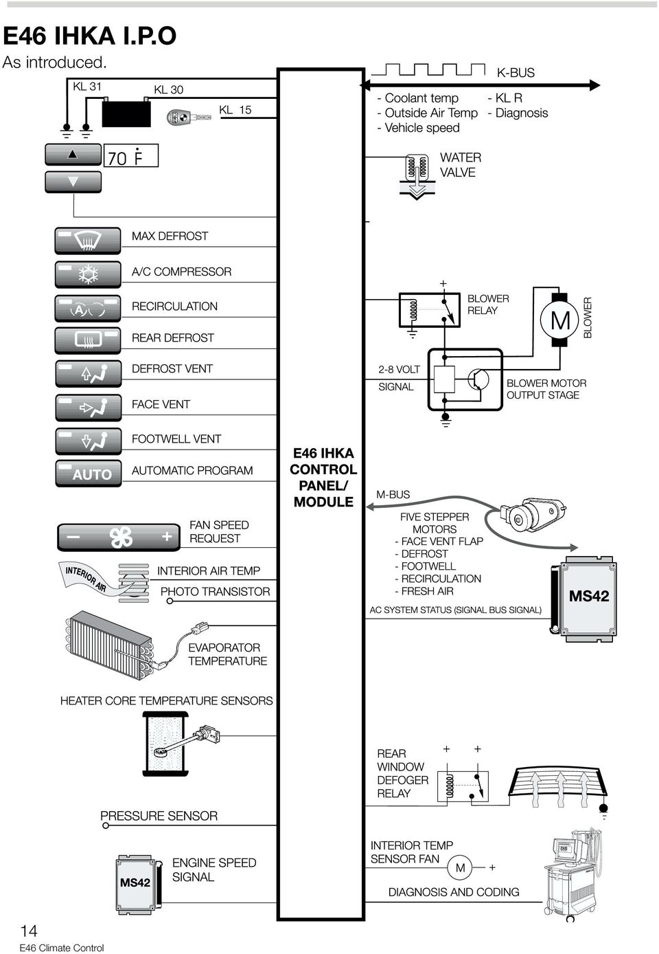
14 E46 IHKA I.P.O As introduced. 14
15 SOLAR SENSOR Model: E38, E39, E46 Production Date: E38 3/99, E46 9/99, E39 9/00 Objectives After completing this module you should be able to: Describe the operation of the solar sensor as it applies to the IHKA systems. List the output functions effected by the solar sensor input. Describe how the solar sensor affects the various output functions. 15

16 Purpose of the System: The purpose of the solar sensor is to compensate the climate control system s output for the radiant heating effect of the sun. This will aid the IHKA in maintaining a constant comfort level, in the vehicle s interior, during all driving conditions. The function of heating and air conditioning systems in BMW vehicles is to provide the driver and passengers a comfortable atmosphere regardless of conditions outside of the vehicle. Based on the temperature signal inputs, blower setting, flaps portioning, program settings in the control module and influencing variables, the IHKA control module is able to process these inputs to achieve the desired comfort level. The following input variables are processed by the IHKA module: Interior temperature Heat exchanger temperature Ventilation temperature (E38) Evaporator temperature Air volume setting Engine temperature and RPM Exterior temperature The processed variable Y-factor is determined by using the above inputs. The Y-factor then represents how much adjustment is necessary by the IHKA module to achieve the set temperature. 16

17 Solar Radiation Solar radiation, from the sun, passes through the earths atmosphere in the form of light (both visible and non-visible) and heat (sunshine). To date, the influence of solar radiation on the climate control system in the vehicle has only been compensated for by an average value stored in the control module and based on control settings and outside temperature values. Solar Sensor The solar sensor can detect the amount of solar radiation that is influencing the temperature and climate in the vehicles interior. The IHKA control module monitors the input from the solar sensor and adds the value to its processing factors. The settings of the climate control system are changed to compensate for this additional influence. The settings of the following IHKA components are adjusted to compensate for changes in solar radiation: Blower - The blower curve is changed Stratification (mixing flaps) - The stratification outlet air temperature is changed (not E46) Ventilation - The opening angles of the ventilation flaps are changed. 17

18 Components: In the E38, The solar sensor is integrated in the housing of the anti-theft warning system LED. The warning indicator LED is installed on the outlet grille in the top center of the instrument panel where solar radiation can directly reach the solar sensor. The DWA LED with solar sensor is an additional wiring harness with a 4-pin plug connector. DWA LED with integrated solar sensor DWA LED plug connector 1 DWA LED/SOLAR 2 SENSOR MODULE 4-pin solar 3sensor plug connector 18

19 The solar sensor consists of two photoresistors, which are integrated on the left and right sides of the DWA housing next to the DWA LED. The photoresistors sense the different intensity levels of the solar radiation DWA LED dismantled; housing and pc-board with LED and solar sensor housing 1 The photoresistor on the right is fitted under the plastic cover 2 The photoresistor on the left is fitted under the plastic cover 3 PC-board, DWA LED and solar sensor 4 DWA LED housing SOLAR SENSOR The E46 solar sensor is located in the right defroster outlet at the base of the windshield. The E46 sensor contains one photoresistor for sensing solar radiation. 19

20 System Operation The solar sensor receives power (5 volts) and ground from the IHKA control module. The module then reads the voltage drop across the photoresistor and determines the degree of solar heating based on the change in voltage. The voltage drop across the photoresistor increases as solar radiation increases. The IHKA control module monitoring voltage will decrease indicating an increase in solar heating. The module processes the input every 10 seconds and checks it for plausibility based on a limit value monitoring function. Values outside the limit indicate a malfunction and the signal from the sensor is ignored by the module. As solar radiation levels increase, the control curves, stored in the IHKA module, for the blower fan, mixing flaps and ventilation (face vent) flaps are shifted to compensate for the additional heat. The solar sensor inputs to the IHKA control module can influence the settings on the relevant side (driver/front passenger) on the E38 and E39. No separate regulation is possible on the E46. When driving at night, during cloudy periods or through tunnels, the control maps are shifted back to their base settings. 20

21 CONTROL CURVES OPERATION Blower Intervention The graph below illustrates the solar influence on the blower fan with a constant Y factor and the solar influence changing from 0 th 100%. Blower power curves The middle curve illustrates a blower curve without any solar influence. At a constant Y factor of 20%, the solar influence on the IHKA control module will cause the blower curve to shift as the radiation increases from 0 to 100%. With a solar influence of 0%, curve B is used, providing 25% power to the blower. As the solar influence increases, the curve shifts upward until the solar influence reaches 100%. At this point, curve A is used providing 36% power to the blower. During heating, the blower power decreases as solar influence increases. While cooling, the blower power will increase as solar influence increases. 21
22 Stratification (Temperature Intervention) E38 only The mixing flaps will open less in the direction of heat for blending air as the solar influence increases. The graph below represents the influence of the solar sensor on the stratification flap settings To illustrate the influence of the solar sensor on the mixing flap position, the Y factor remains constant at 20%. With a solar influence of 0% curve A is adopted for the various outside temperatures. As the outside temperature decreases, the mixing flap is moved toward the warmer setting blending more heat. With a solar influence of 100% curve B is adopted for the various outside temperatures. As the outside temperature decreases, the mixing flap is still moved toward the warmer setting but it does not move as far. The solar influence is compensating to provide the same comfort level. With the mixing flap thumbwheel at 100 or 0% (full hot or cold), the flaps are in the default position and there will be no solar influence. The left and right mixing flaps are controlled independently based on the individual settings and left and right solar sensor inputs. 22
23 Ventilation Intervention (Center Vent Air Distribution) The influence of the solar sensor on the ventilation flaps is shown in the graph below. The normal curve B applies when there is no solar sensor influence 0%, or if the sensor is defective. The maximum curve A applies when the solar influence is 100%. The ventilation flaps will close less as the solar influence increases. This allows more cool air from the center vents as the solar radiation increases. This adjustment is also independently adjustable on the E38 based on the left/right solar sensor inputs. 23
24 DIAGNOSIS Troubleshooting of the solar sensor (left/right) is carried out through the IHKA diagnostic program using the DIS or MoDiC. Status displays for the solar sensor input are available in percentages. The status displays can be checked while applying a light or heat source to the solar sensor to view the change in value. The E46 diagnostic program for the IHKA system contains a test module B for testing the operation of the solar sensor. The IHKA control module monitors the solar sensor and will set a fault code for: Shorts to B+ or ground Open circuits The IHKA control module will function as a system without solar influence correction if the sensor is defective. Recognition of the solar sensor and its influencing capabilities is enabled via ZCS coding. Remember to adopt the code whenever possible to avoid loosing car/key memory function changes. Also the IHKA control module must be disconnected from B+ before coding can become permanent. 24
25 Workshop Hints E38 vehicles To remove the solar sensor from an E38, refer to TIS - RM , removal of the center outlet grille at the top of the dash. After removal of the grille, disconnect the plug connector of the DWA indicator and solar sensor and pull the sensor from the grille. E46 vehicles Removal of the E46 solar sensor requires removal of the instrument panel. However, for testing purposes, the connector is located in-line, attached to the harness for connector X610. X18786 in-line connector for Solar Sensor. 25
26 E46 IHKR Model: E46 (325i/it/Ci/Cic, M3) Production Date: From 9/00 Objectives After completing this module you should be able to: Recognize the climate control functions performed by the IHKR system. Identify the changes compared to the E46 IHKA system. Understand the method of temperature control used by the IHKR. Describe how the A/C compressor is controlled. 26
27 Purpose of the system Beginning M.Y. 2001, the 325i/it/Ci/Cic and M3 are fitted with IHKR as standard equipment. The IHKA system is available as an option on these models. IHKR is a semi-automatically regulated heating and air-conditioning system, similar to the IHKR introduced for the 2001 E39 and E53. The purpose of the system is to allow the vehicle occupants to select the desired temperature, air outlet distribution and volume manually. The system then automatically regulates the temperature of the cabin based on the manual settings. The functions provided by the E46 IHKR are: Control of the blower. Air distribution control. Stratification flap controlled by a bowden cable Temperature Control Service Station feature Air conditioning request to DME Recirculation air Ram effect air compensation Rear window defroster 27
28 System Components The E46 IHKR consists of the following components: IHKR control unit with operating controls IHKR integrated heater and air conditioning case Heater core temperature sensor Evaporator temperature sensor Refrigerant circuit pressure sensor Double cage blower motor and final stage Water valve Air distribution micro-switch M-bus with 3 smart stepper motors: - Air distribution - Fresh air/re-circulation left (high speed motor) - Fresh air/re-circulation right (high speed motor) Compressor relay (DME controlled) Auxiliary fan (DME controlled) Rear window defroster relay K-bus interface The following signals are transmitted and received over the K-bus: - Vehicle speed - Engine speed - Coolant temperature - Outside temperature - Terminal 15, 61, 50,58G (panel lighting) - Compressor load - Diagnosis and coding - Compressor request Fresh air Micro-filter 28
29 DSC III kjhsdfkhsdflkhsdlkfjhlkjghkg lkdkfljdflkjdsfljdslfjldskjflkjdflk ldsflsdfklhdsfhsdfhsdkhfkhsdf kldjfkljdfkjdskfkjdskfjkljdfkldsfk kjsdfkljsdfkdsfkjdsfkljsdfkjds ldjsfklkjsdfkldsjfkdsjfkdsfkdfklk E46 IHKR I.P.O BLOWER MOTOR OUTPUT STAGE - + KL31 KL30 KL15 + M FAN SPEED WATER VALVE KL30 A/C REQUEST RE-CIRCULATION M-BUS - FRESH AIR/RECIRC LEFT - FRESH AIR/RECIRC RIGHT - AIR DISTRIBUTION REAR DEFROST E46 IHKR TEMPERATURE CONTROL REAR WINDOW DEFROST RELAY KL 15 KL 30 AIR DISTRIBUTION POTENTIOMETER EVAPORATOR TEMPERATURE COMPRESSOR CONTROL KL30 REFRIGERANT PRESSURE KO REL DME AIR DISTRIBUTION MICRO-SWITCH KL30 M AUXILIARY FAN CONTROL HEATER CORE TEMPERATURE K-BUS BMW DIS BMW DIS LSZ PANEL ILLUMINATION 58G BMW DIS 29
30 IHKR control unit with operating controls The IHKR control unit is incorporated into the control panel. The control panel consists of three buttons and three rotary dials. The control unit communicates over the K bus. 1. Blower control potentiometer 2. Recirculation button 3. Temperature control potentiometer 4. Air distribution potentiometer X608 X610 6 pin 18 pin Air conditioning request button 6. Rear window defroster button X613 X pin M-bus 6 pin IHKR Case The E46 IHKR case is similar in design to the E46 IHKA heating and A/C case. 1. Heater Core Temp. Sensor 2. Heater core 3. Evaporator Temp Sensor 4. Evaporator 5. Double Cage Blower 30
31 Principle of operation Blower adjustment The blower rotary dial potentiometer has four settings. Each progressive step represents a 25% increase in blower volume. The control unit determines the desired blower setting by the signal from the potentiometer and then sends a voltage signal to the final stage unit. The voltage signal to the final stage unit ranges from 1.8V to a maximum of 7.1V (Normal blower power in Key Memory). The final stage unit then regulates blower motor voltage to control the blower volume. There is no automatic influence on the blower setting. The blower control potentiometer is the master on/off switch for the IHKR system. The water valve is closed (energized) in the blower zero (off) position. The LEDs for re-circulated air and air conditioning are switched off and the compressor is switched off. The rear defroster operation is not affected by the system being switched off. Air distribution The selection of air distribution is carried out using the rotary dial potentiometer (42 steps). Each step of the potentiometer represents a percentage. The percentage indicates the desired air distribution setting. BLEND OF BLEND 90 FULL DEFROST 0 8 BLEND OF BLEND Movement of the stratification flap for face ventilation is carried out by rotating a thumb wheel between the face vent discharge nozzles. The thumb wheel is connected to a bowden cable that moves the flap. FULL FOOTWELL FULL VENT The air distribution for defrost, ventilation and footwell is performed by a single air distribution stepper motor that is connected to the M-bus and controlled by the IHKR control unit. BLEND OF BOTH 31
32 The stepper motor drives a cam/lever assembly (1) that articulates all three air distribution flaps. The position of the cam is confirmed by the air distribution micro-switch (2). The air distribution micro-switch is provided 5V by the IHKR control unit. The micro switch is closed by the rotating cam lobe in two positions: Full defrost 97% to 0% Mixed face vent/footwell 37% (quick confirmation) When the switch is closed the signal at the control unit goes low, informing the control unit that it has reached that particular position. The display in diagnosis recognizes this position as off. Located on the right side of the IHKR case A reference run is initiated the first time KL30 is switched on to the IHKR control unit. The reference run is required to determine the position of the cam disc. The cam disc is rotated until the micro-switch sends a signal to the control unit. After the reference run is completed, the control unit recognizes what position the cam disc is in and thus the position of all three air distribution flaps. If the air distribution micro-switch is not able to produce a signal at the correct position, the control unit will continue to operate the stepper motor at an estimated position. Eventually the air distribution setting will not match the actual output. The air distribution micro-switch circuit is fault monitored. Temperature control The desired interior temperature is set with the rotary dial potentiometer (34 steps). The face of the dial itself has no marked temperatures, just a blue, white and red line that represents a comfort zone. All of the air flowing into the IHKR housing must pass through the evaporator first before being re-heated by the heater core. This is the principle used by all IHKR and IHKA systems. The IHKR maintains the temperature of the discharge air by cycling the water valve to regulate the temperature of the heater core. The duty cycle applied to the water valve is based on the Y-factor (correcting variable) and other variables. 32
33 The Y-factor of the E46 IHKR is determined by: Setting of the temperature control dial Outside temperature (from Kombi via the K-bus) Heater core temperature Automatic temperature control is switched off when the temperature control dial is turned all the way to the left (blue: water valve closed) or right (red: water valve full open) stop. Each step of the potentiometer represents a temperature from max. cold (10 o C) to max. warm (49.5 o C). This temperature value is combined with the outside temperature to form a calculated set-point. The E46 IHKR does not use an interior temperature sensor. The Y-factor is then determined by comparing the calculated set-point to the actual value of the heater core sensor which is in the stream of air to the outlet ducts. In addition to the Y-factor, the control unit evaluates coolant temperature and engine RPM to determine water valve opening time. The valve opening times are: 0 ms at max. COLD 3600 ms at max. WARM Engine map cooling Map cooling is used by the DME MS 43.0 for the M54 engines. This can create very high coolant temperatures which could be damaging to the climate control system. If the heater core temperature exceeds 80 o C, the water valve is closed until the temperature drops below 80 o C. If the temperature at the heater core increases above 93 o C (i.e. water valve faulty), the IHKR will signal the DME (via K-bus/Kombi/CAN) to energized the map cooling thermostat. Service Station Feature The service station feature prevents the vehicle occupants from getting a blast of hot air after the vehicle is restarted following a short stop. The water valve is powered closed by the IHKR control unit for three minutes after shut-off. This prevents the heater core from being flooded with hot coolant. 33
34 UNLEADED GASOLINE ONLY SERVICE ENGINE SOON km/h! miles BRAKE ABS Air Conditioning control The air conditioning system is switched on by pressing the snow flake button and having the blower dial on position 1 or greater. The LED in the button signals that the A/C is in stand-by. The IHKR control module sends the following signals to the DME over the K-bus-Kombi- CAN -bus connection: IHKR on stand-by (signal AC) Request for A/C activation (signal KO) Calculated compressor load Request for auxiliary fan The IHKR determines the load torque for compressor activation and required auxiliary fan speed from the pressure sensor mounted on the high side line next to the receiver dryer. The refrigerant pressure sensor provides a voltage input signal (0-5 volts) to the IHKR. The voltage value increases as pressure in the high side refrigerant circuit increases. The IHKR processes this signal to determine the calculated load that will be placed on the engine when the compressor is switched on. Pressure values that are too high or too low will cause the compressor to be switched off. Once all of the criteria for compressor operation have been met, the DME control module will activate the compressor relay to energize the compressor magnetic clutch. Control of the evaporator temperature is carried out by the IHKR signalling the DME to shut off the compressor when the evaporator reaches the freezing point. K-Bus: Signal AC/KO EML MPH /min 5 x CAN-Bus KOMBI The IHKR cycles the compressor at 1 o C if the outside temperature is above 68 o F. The compressor is cycled at 3 o C if the outside temperature is below 68 o F. IHKR DME Evaporator Temp. 34 Refrigerant Pressure Auxiliary Fan OUTPUT STAGE M KL30 K19 relay Compressor
35 Air Intake The fresh air/re-circulation flaps are controlled by a separate stepper motor for the left and right side. Fresh air flaps The stepper motors are controlled by the M- bus and are located on the left and right sides of the housing inside the passenger compartment. The fresh air flaps are closed and the re-circ doors are opened when the re-circ. button is pressed with the system switched on. When the key is turned off with re-circulation on, the fresh air flaps will open. Re-circulation memory in the IHKR control unit is 15 minutes. If the vehicle is started within 15 minutes the re-circulation setting will be restored. If the system is shut off with the blower switch, the re-circulation function will have to be reenabled. Ram effect air compensation Similar to IHKA, when the fresh air flaps are open their position is affected by vehicle road speed. This is to prevent an increase in air volume to the cabin with increasing vehicle speed. The IHKR receives the vehicle speed input every 2 seconds over the K-bus from the Kombi. At a speed of 36mph the fresh air flaps will close progressively until the vehicle reaches 96mph, at which time the opening of the flaps will be 20%. 100 % OPENING ANGLE OF FRESH AIR FLAPS 60 % 40 % - 30 % - 20 % ROAD SPEED (MPH) 35
36 Rear window defroster operation (All models) The rear window defroster is controlled via a request from the button on the panel. After switching on for the first time, the rear window is heated for 17 minutes. Output voltage to the window is provided by the K13 rear defogger relay. After automatic switch off, if the button is pressed once again the control unit will provide another 17 minutes of operation. If the vehicle voltage drops below 11.4V during this second heating operation the function is stopped, however the LED on the button will not be extinguished. If voltage increases past 12.2V for at least one second, operation will resume. The control circuit of the convertible varies slightly due to the folding top. Defroster operation specific to Convertibles CVM Top closed and locked = 12V K13 Rear window defogger relay K99 Rear defogger relay 31 IHKR Control unit Rear window defroster When the button is pressed on the IHKR control panel, relay K13 is energized. K13 supplies KL 30 to defroster relay K99. Relay K99 is energized when the KLR is switched on and the soft top is closed and locked to the windshield frame. This completes the circuit and allows the rear window to be heated. If the soft top is lowered during defroster operation, voltage to relay K99 is interrupted by the CVM to prevent the rear window grid from heating when the top is lowered into the storage compartment. 36
37 DSC III kjhsdfkhsdflkhsdlkfjhlkjghkg lkdkfljdflkjdsfljdslfjldskjflkjdflk ldsflsdfklhdsfhsdfhsdkhfkhsdf kldjfkljdfkjdskfkjdskfjkljdfkldsfk kjsdfkljsdfkdsfkjdsfkljsdfkjds ldjsfklkjsdfkldsjfkdsjfkdsfkdfklk Workshop Hints Diagnosis Diagnosis of the E46 IHKR system is carried out using the DISplus or MoDiC. The IHKR is connected to the diagnostic bus via the K-bus/Kombi connection. The system uses the E46 test module driven diagnostic concept for troubleshooting faults with the system. Control Unit Functions: Expert mode diagnosis available at any time during troubleshooting. To enter: press the Control Unit Functions button at the lower right corner of the screen. The contents are: Identification Clear Fault Memory Read Fault Memory Component Activation Status Requests Service Functions: Provides access to specialized test modules used as post repair procedures. To enter: Function selection Service Functions Body Heater- A/C control Deactivate transport-lock function BMW DIS BMW DIS BMW DIS Test Modules: Faults with the E46 IHKR can be diagnosed using fault or symptom driven test modules. To begin diagnosis: Perform the Short Test Select a vehicle symptom from the Symptom Selection page Select a test module from the Test Plan page Press the Test Schedule button Test module are written in the E46 Diagnostic Concept. 37
38 DSC III kjhsdfkhsdflkhsdlkfjhlkjghkg lkdkfljdflkjdsfljdslfjldskjflkjdflk ldsflsdfklhdsfhsdfhsdkhfkhsdf kldjfkljdfkjdskfkjdskfjkljdfkldsfk kjsdfkljsdfkdsfkjdsfkljsdfkjds ldjsfklkjsdfkldsjfkdsjfkdsfkdfklk SERVICE ENGINE SOON km/h K-Bus Coding Coding must be performed if the IHKR control unit is replaced. ZCS coding is found in the Coding and Programming selection from the start screen or when pressing the Change button. Follow on-screen instructions to remove KL 30 power to the IHKR control unit. This step is necessary to complete the coding process. Car and Key Memory When troubleshooting complaints with the E46 IHKR it is important to note that because the Car/Key Memory feature can change the operation of the system, a review of the settings should be made prior to beginning troubleshooting. D-Bus UNLEADED GASOLINE ONLY /min 5 x MPH! EML miles BRAKE ABS BMW DIS BMW DIS BMW DIS Print Change End Services BMW Coding/programming SELECTION 1 CAR MEMORY 2 KEY MEMORY 3 ZCS CODING 4PROGRAMMING 5 ALIGNMENT EWS-DME 6 ALIGNMENT EWS-DDE Note Only Key Memory selections are possible for the E46 IHKR. The selections are: Set Blower Power (Raise, Normal, Lower) Correction Set Temperature (raise/lower) A/C on at key on (Automatic activation of the compressor control when the ignition is switched on.) 38
39 Review Questions 1. Where is the interior temperature sensor located in a vehicle equipped with IHKA? What is this input used for? 2. How does the IHKA control the auxiliary fan? What inputs are used by the IHKA to determine the fan speed? 4. A customer complains that every time he enters his car the AC compressor is switched on automatically. What could be causing his complaint? 5. Describe briefly how the influence of Solar radiation affects the IHKA settings. 6. How can a technicaian test for the correct operation of the Solar Sensor? 7. What is the purpose for the RPM input to the IHKA? 39
40 Review Questions 8. What is the Voltage range of the control signal from the IHKR to the blower final stage? 9. Which components are responsible for the movement of the air distribution flaps? What role does the air distribution micro-switch play? (IHKR system) 10.How does the IHKR determine a Y-factor if the system does not use an interior temperature sensor? 11.How does the IHKR signal the DME when compressor activation is requested? Discuss what information is exchanged. 12.What three stepper motors are located on the IHKR M-Bus? What is an M-Bus? 13.Which additional component is used in the rear defrost circuit of a convertible E46, as compared to a hard top? 40
E85 Heating / Air Conditioning System
 Table of Contents E85 Heating / Air Conditioning System Subject Page E85 Heating / Air Conditioning System...3 IHKS...3 IHKS Components...3 IHKS Principle of Operation... 8 IHKA...11 IHKA Components...11
Air conditioning, electrical testing
 just a test. Air conditioning, electrical testing 01-253 Wire and component test using VAG1598 A test box Special tools and equipment VAG 1598 A test box and VAG 1598/11 adapter cable and VAG 1598/12 VAG1526
Section 6. Introduction to Automatic A/C. Automatic Temperature Control
 Automatic Control Introduction to Automatic A/C The heating, ventilation and air conditioning (HVAC) system in a house contains a wall-mounted thermostat to control outlet temperatures, distribution and
Air Conditioning System
 Air Conditioning System 1 Chonan Technical Service Training Center Chonan Technical Service Training Center 2 Objectives To understand the components of air conditioning system. To understand the control
Heater and Air Conditioner, Blend Air System, Troubleshooting 83.06
 A/C Performance Diagnosis Problem Warm Airflow When the Air Conditioner is On, A/C Not Working, or Poor A/C Performance (dash outlet temperature is too high) Problem Warm Airflow When the Air Conditioner
PROCEDURES FOR SELF DIAGNOSTICS
 PROCEDURES FOR SELF DIAGNOSTICS Baum Tools Unlimited Inc. March 31, 1999 TAU 2.1 READING ACTUAL VALUES 1. Remove the operating console from the TAU 2. At the upper side of the operating consol there is
V.A.G. Service. CLIMAtronic. CLIMAtronic USE AT YOUR OWN RISK. This document is an UNOFFICIAL translation of: V.A.G. Service
 V.A.G. Service CLIMAtronic Construction and Function Self-Study Program 135 This document is an UNOFFICIAL translation of: V.A.G. Service CLIMAtronic Konstruction and Funktion Selbststudienprogramm Nr.
A/C-HEATER SYSTEM - AUTOMATIC
 A/C-HEATER SYSTEM - AUTOMATIC 1995 Volvo 850 1995-96 Auto. A/C-Heater Systems Volvo 850 * PLEASE READ THIS FIRST * WARNING: To avoid injury from accidental air bag deployment, read and carefully follow
01-3 0000-00 6810-20 AIR CONDITIONING SYSTEM 1. FFH SPECIFICATION AIR CONDITIONING SYSTEM RODIUS 2004.09
 0000-00 01-3 6810-20 1. FFH SPECIFICATION 01-4 0000-00 2. SYSTEM LAYOUT AND COMPONENTS 0000-00 01-5 01-6 0000-00 3. FFH GENERAL INFORMATION The system is to increase the coolant temperature quickly by
Section 7. Evaporator thermistor. Under-and-over pressure safety switches. Connections to the ECU
 Automatic Temperature Control Diagnosis and Repair Diagnosis of Automatic A/C Systems The most common automatic A/C system malfunctions tend to be the result of basic air conditioning problems. These problems
TSB #: 74 Date: 9/7/2013 HOLDEN VE/WM HVAC & A/C DIAGNOSTIC HINTS
 HOLDEN VE/WM HVAC & A/C DIAGNOSTIC HINTS TSB #: 74 Date: 9/7/2013 Initial Once Read: In this technical bulletin we have listed diagnostic advice relating to the Holden VE/WM HVAC & A/C system. This information
Basic Technology Series
 Basic Technology Series Fundamentals of Car Air Conditioning 2007 Air Conditioning #003 The Rear Cooler Construction Fan Fan Filter Figure A : Trunk Figure B : Overhead Dual Air-Conditioner In This Issue
E70 Climate Control Systems (IHKA, IHKA w/fka, Third Row HV)
") Table of Contents (IHKA, IHKA w/fka, Third Row HV) Subject Page Introduction..................................................5 System Functions.............................................6 Temperature
Table of Contents (IHKA, IHKA w/fka, Third Row HV) Subject Page Introduction..................................................5 System Functions.............................................6 Temperature
HVAC SYSTEM (AUTO A/C) (DIAGNOSTICS) AC
 (DIAGNOSTICS) AC") HVAC SYSTEM (AUTO A/C) (DIAGNOSTICS) AC Page. Basic Diagnostic Procedure.... General Description...3 3. Electrical Components Location...6 4. A/C Control Module I/O Signal...8 5. Self-diagnosis...0 6.
HVAC SYSTEM (AUTO A/C) (DIAGNOSTICS) AC Page. Basic Diagnostic Procedure.... General Description...3 3. Electrical Components Location...6 4. A/C Control Module I/O Signal...8 5. Self-diagnosis...0 6.
Electronic Power Control
 Service. Self-Study Programme 210 Electronic Power Control Design and Function With the Electronic Power Control system, the throttle valve is actuated only by an electric motor. This eliminates the need
HVAC SYSTEM (HEATER, VENTILATOR, AND A/C)
") HVAC SYSTEM (HEATER, VENTILATOR, AND A/C) HEATER SYSTEM 1. Heater System A: GENERAL A semi-center type integrated air conditioning unit is used, where a high performance heater core and an evaporator core
HVAC SYSTEM (HEATER, VENTILATOR, AND A/C) HEATER SYSTEM 1. Heater System A: GENERAL A semi-center type integrated air conditioning unit is used, where a high performance heater core and an evaporator core
HEATER, AIR CONDITIONING AND VENTILATION
 55-1 GROUP 55 HEATER, AIR CONDITIONING AND VENTILATION CONTENTS GENERAL DESCRIPTION 55-2 HEATER AND AIR CONDITIONING SYSTEM 55-4 HEATER CONTROL 55-6 A/C-ECU 55-7 A/C COMPRESSOR 55-9 CONDENSER 55-9 DUCT
AUTOMATIC CONTROL HEATING, VENTILATION AND AIR CONDITIONING SYSTEM
 SECTION 7D AUTOMATIC CONTROL HEATING, VENTILATION AND AIR CONDITIONING SYSTEM TABLE OF CONTENTS Description and Operation... 7D- General... 7D- FATC Control... 7D- FATC Input/Output Routing Diagram...
3. AIR CONDITIONER CONTROLLER (UNIT)
") 9 3. AIR CONDITIONER CONTROLLER (UNIT) Functions of Full Automatic Air Conditioner ler 1 1. Temp SW 2. Auto SW 3. OFF SW 4. Amb SW 5. Mode SW 6. Blower SW 2 3 10 5 8 7 9 Temperature control: Air mix actuator
9 3. AIR CONDITIONER CONTROLLER (UNIT) Functions of Full Automatic Air Conditioner ler 1 1. Temp SW 2. Auto SW 3. OFF SW 4. Amb SW 5. Mode SW 6. Blower SW 2 3 10 5 8 7 9 Temperature control: Air mix actuator
The Phaeton Heating and Air Conditioning System
 Service. Self-Study Programme 271 The Phaeton Heating and Air Conditioning System Design and Function An outstanding climate As a luxury performance saloon, the Phaeton is fitted with a four-zone cabin
Touareg Heating/air-conditioning system
 Service. Self-Study Programme 301 Touareg Heating/air-conditioning system Design and function The automobile is accompanying people more and more in their recreational time. In addition to the pure transport
EVANS ELECTRONIC TEMPERATURE CONTROL TROUBLESHOOTING GUIDE for systems equipped with electric coolant valve and external PC board.
 EVANS ELECTRONIC TEMPERATURE CONTROL TROUBLESHOOTING GUIDE for systems equipped with electric coolant valve and external PC board. This Troubleshooting Guide covers the electric coolant valve and control
Electronically Controlled Clutchless or Variable Drive Compressors
 Electronically Controlled Clutchless or Variable Drive Compressors On many new air conditioning systems, such as Lexus, Cadillac, Chrysler, and others, a new type of compressor has been fitted. There are
VW Climatronic (by Hella) Self-Diagnostics
 Self-Diagnostics") VW Climatronic (by Hella) Self-Diagnostics Original Author: Roger, Location: Greater Frankfurt am Main Posted on: 09-09-2004 Original Title: Eigendiagnose an der VW Climatronic von Hella Translation by:
VW Climatronic (by Hella) Self-Diagnostics Original Author: Roger, Location: Greater Frankfurt am Main Posted on: 09-09-2004 Original Title: Eigendiagnose an der VW Climatronic von Hella Translation by:
Electrical Systems - IQAN Digital Control System. IQAN Control System Components... 5.1.3
 Section 5.1 Electrical Systems - IQAN Digital Control System IQAN Control System Components........................... 5.1.3 IQAN Operational Description: At Machine Startup.....................................
AIR CONDITIONING SYSTEM (FOR AUTOMATIC AIR CONDITIONING SYSTEM)
") 2008 HVAC Air Conditioning - RAV4 AIR CONDITIONING SYSTEM (FOR AUTOMATIC AIR CONDITIONING SYSTEM) PRECAUTION 1. IF ANY OF FOLLOWING CONDITIONS ARE MET, KEEP ENGINE IDLING WITH A/C ON (ENGINE SPEED AT LESS
2008 HVAC Air Conditioning - RAV4 AIR CONDITIONING SYSTEM (FOR AUTOMATIC AIR CONDITIONING SYSTEM) PRECAUTION 1. IF ANY OF FOLLOWING CONDITIONS ARE MET, KEEP ENGINE IDLING WITH A/C ON (ENGINE SPEED AT LESS
TOYOTA ELECTRONIC TRANSMISSION CHECKS & DIAGNOSIS
 Checks and Adjustments The transmission requires regular maintenance intervals if it is to continue to operate without failure. As we discussed in previous sections, transmission fluid loses certain properties
ELECTRICAL WIRING (R.H. DRIVE VEHICLES)
") C-1 ELECTRICAL WIRING (R.H. DRIVE VEHICLES) CONTENTS GENERAL.......................... 3 WIRING HARNESS CONFIGURATION DIAGRAMS......................... 4 ENGINE COMPARTMENT................ 4 DASH PANEL...........................
C-1 ELECTRICAL WIRING (R.H. DRIVE VEHICLES) CONTENTS GENERAL.......................... 3 WIRING HARNESS CONFIGURATION DIAGRAMS......................... 4 ENGINE COMPARTMENT................ 4 DASH PANEL...........................
Automatic air conditioning system
 Automatic air conditioning system Airflow and outlets are automatically adjusted according to the temperature setting. Control panel Windshield defogger Driver s side temperature control dial Air conditioning
INSTRUMENT PANEL. 1995 Volvo 850 DESCRIPTION & OPERATION. 1995-96 ACCESSORIES & EQUIPMENT Volvo Instrument Panels
 INSTRUMENT PANEL 1995 Volvo 850 1995-96 ACCESSORIES & EQUIPMENT Volvo Instrument Panels 850 WARNING: When working around steering column and before performing repairs, disconnect and shield battery ground
6. Diagnostics for A/C System Malfunction
 6. A: A/C OR SELF-DIAGNOSIS SYSTEMS DO NOT OPERATE TROUBLE SYMPTOM: Set temperature is not indicated on the display, switch LEDs are faulty or switches do not operate. Self-diagnosis system does not operate.
Heating/Ventilation. As regards the heating and ventilation system in the Fabia, two equipment versions are available:
 Heating/Ventilation SP 32_111 As regards the heating and ventilation system in the Fabia, two equipment versions are available: a heater unit an automatic heater/air conditioning unit. A recirculated air
HEATER WITH OPERATION
 2002-05 HVAC Air Conditioning & Heating Systems - Repair Instructions - Cooper (1.6L) R50/W10 & Cooper S HEATER WITH OPERATION 64 11... INSTALLING SERVODRIVE Installation: If necessary, align shaft of
Programmable Thermostat MODEL 3312026.XXX With Dehumidify 3312024.XXX With Out Dehumidify
 Comfort Control Center 2 Thermostat Operating Instructions Programmable Thermostat MODEL 3312026.XXX With Dehumidify 3312024.XXX With Out Dehumidify TABLE OF CONTENTS About your new thermostat Features...2
How To Diagnose And Fix A Car With A Power Control Unit
 55- GROUP 55 HEATER, AIR CONDITIONING AND VENTILATION CONTENTS GENERAL DESCRIPTION......... 55-3 SERVICE PRECAUTIONS......... 55- CAUTION LABELS................... 55-........ 55-5 INTRODUCTION TO HEATER,
THERMO KING TRUCK & TRAILER UNIT ALARM CODES THIS DOCUMENT SHOWS ALL CURRENT ALARM CODES FOR THERMO KING TRUCK AND TRAILER UNITS.
 THERMO KING TRUCK & TRAILER UNIT ALARM CODES THIS DOCUMENT SHOWS ALL CURRENT ALARM CODES FOR THERMO KING TRUCK AND TRAILER UNITS. NOT ALL CODES ARE POSSIBLE ON ANY INDIVIDUAL UNIT. IF THE ALARM APPLIES
Transport Air Conditioning TRANSPORT AIR CONDITIONING OPERATOR S MANUAL. for SPLIT SYSTEM. Bus Air Conditioning Units.
 R Transport Air Conditioning TRANSPORT AIR CONDITIONING OPERATOR S MANUAL for SPLIT SYSTEM Bus Air Conditioning Units T--326 Rev -- OPERATOR S MANUAL BUS AIR CONDITIONING UNITS GEN IV & GEN V CONTENTS
VEHICLE SPEED CONTROL SYSTEM
 PL VEHICLE SPEED CONTROL SYSTEM 8H - 1 VEHICLE SPEED CONTROL SYSTEM TABLE OF CONTENTS page DESCRIPTION AND SPEED CONTROL SYSTEM...1 SPEED CONTROL SERVO-PCM OUTPUT....2 SPEED CONTROL SWITCHES PCM INPUT...2
HVAC. (w) HVAC SYSTEM. Blower unit. (See BLOWER UNIT REMOVAL/INSTALLATION.) (See BLOWER UNIT DISASSEMBLY/ASSEMBLY.) Air filter
 HVAC SYSTEM. Blower unit. (See BLOWER UNIT REMOVAL/INSTALLATION.) (See BLOWER UNIT DISASSEMBLY/ASSEMBLY.) Air filter") HVAC HVAC SYSTEM Blower unit 1 (See BLOWER UNIT REMOVAL/INSTALLATION.) (See BLOWER UNIT DISASSEMBLY/ASSEMBLY.) Air filter 2 3 (See AIR FILTER REMOVAL/INSTALLATION.) (See AIR FILTER INSPECTION.) A/C unit
HVAC HVAC SYSTEM Blower unit 1 (See BLOWER UNIT REMOVAL/INSTALLATION.) (See BLOWER UNIT DISASSEMBLY/ASSEMBLY.) Air filter 2 3 (See AIR FILTER REMOVAL/INSTALLATION.) (See AIR FILTER INSPECTION.) A/C unit
Aerosphere Midibus. Air Conditioning System. Operation Manual. Aerosphere Midibus 05/2013 P.N. 10000038A
 Air Conditioning System Operation Manual Aerosphere Midibus 05/2013 P.N. 10000038A To receive the best performance from the air conditioning system, we suggest carefully reading this manual before operating
14. Troubleshooting Guide
 14. Guide 14.1 Refrigeration Cycle System In order to diagnose malfunctions, ensure the air conditioner is free from electrical problems before inspecting the refrigeration cycle. Such problems include
specializing in AIR CONDITIONING, PARTS AND SYSTEMS for your classic vehicle PERFECT FIT IN-DASH HEAT/ COOL/ DEFROST 1967-72 CHEVROLET PICKUP
 specializing in AIR CONDITIONING, PARTS AND SYSTEMS for your classic vehicle PERFECT FIT IN-DASH HEAT/ COOL/ DEFROST 1967-72 CHEVROLET PICKUP CONTROL & OPERATING INSTRUCTIONS The controls on your new Perfect
TOYOTA ELECTRONIC CONTROL TRANSMISSION
 Electronic Control Transmission (ECT) The Electronic Control Transmission is an automatic transmission which uses modern electronic control technologies to control the transmission. The transmission itself,
INSTALLER S & OWNER S MANUAL
 INSTALLER S & OWNER S MANUAL HVAC INSTALLER: PLEASE LEAVE MANUAL FOR HOMEOWNER DEH 3000 DEH 3000 Part No. 4028539 Dehumidifier & Ventilation System Controller P.O. Box 8680 Madison, WI 53708 TOLL-FREE
INSTRUCTION MANUAL FOR RECREATIONAL REFRIGERATOR/FREEZER MODEL
 INSTRUCTION MANUAL FOR RECREATIONAL REFRIGERATOR/FREEZER MODEL 15-LITER, 20-LITER, 35-LITER, 45-LITER, 60-LITER & 100-LITER SECTION 1 Basic Operation SECTION 2 Cleaning and Storing SECTION 3 Basic Trouble
CC145. Air Conditioning System. Operation Manual. CC145 Compact Cooler 4/2013 P.N. 10000034A
 Air Conditioning System Operation Manual CC145 Compact Cooler 4/2013 P.N. 10000034A To receive the best performance from the air conditioning system, we suggest carefully reading this manual before operating
PASSIVE INFRARED INTRUSION DETECTOR PASSIVE INFRAROOD DETECTOR DETECTEUR D INTRUSION PASSIF INFRAROUGE
 MODEL HAA51 PASSIVE INFRARED INTRUSION DETECTOR PASSIVE INFRAROOD DETECTOR DETECTEUR D INTRUSION PASSIF INFRAROUGE OPERATING MANUAL HAA51 PASSIVE INFRARED INTRUDER DETECTOR INTRODUCTION HAA51 Passive Infrared
Instrument panel. Volkswagen Touareg - Instrument panel. Special tools, testers and auxiliary items required. Release lever T10039
 Volkswagen Touareg - Instrument panel Page 1 / 14 70-1 Instrument panel Tools Special tools, testers and auxiliary items required Release lever T10039 Instrument panel, removing and installing Removing
Single Zone LCD Thermostat Operating Instructions
 Fan Cool Furnace *Heat Pump or Heat Strip On/Off F Single Zone LCD Thermostat Operating Instructions MODEL 3313192.XXX Cool/Furnace 3313193.XXX Cool/Furnace/Heat Pump 3313194.XXX Cool/Furnace/Heat Strip
SERVICE MANUAL 12VDC WALL THERMOSTAT AIR CONDITIONING SYSTEMS ROOFTOP UNITS ONLY
 SERVICE MANUAL 12VDC WALL THERMOSTAT AIR CONDITIONING SYSTEMS ROOFTOP UNITS ONLY! WARNING - SHOCK HAZARD! TO PREVENT THE POSSIBILITY OF SEVERE PERSONAL INJURY, DEATH, OR EQUIPMENT DAMAGE DUE TO ELECTRICAL
Vario Tractors - Fault Codes. Faults. all Vario tractors Tractor / General system. EDC / EMR bus fault. Fault in ECU Programming errors in ECU.
 12/1999 f 1/58 Vario Tractors - Codes 0000 000001 Date Version Page Capitel Index Docu-No. FCT_InitPage 0.0.11 A021; A022 Id rief description Description Consequences Link FENDIAS / Note ECU, EDC; ECU,
ENGINE DIAGNOSTICS & CONTROL
 ENGINE DIAGNOSTICS & CONTROL CONTROL SYSTEM WIRING DIAGRAM Page 1 Page 2 MONITORING SYSTEM AND CONTROL SYSTEM DEVICE RELATIONSHIP CHART : Applicable Component Input Battery Ignition switch A/C switch,
Evaporative emissions system
 just a test. Evaporative emissions system 20-48 Function description of EVAP canister system Depending upon the air pressure and ambient temperature, fuel vapor will form above the level of fuel in the
SWIMMING POOL HEAT PUMP Owners Manual
 SWIMMING POOL HEAT PUMP Owners Manual This manual refers to the 17.0kw and 21.0kw models only. The heat pump unit is sold with a 1 year warranty. In addition there is a 2 year parts warranty on the compressor
INSTALLATION INSTRUCTIONS COMMERCIAL ROOM VENTILATORS WITH EXHAUST
 INSTALLATION INSTRUCTIONS COMMERCIAL ROOM VENTILATORS WITH EXHAUST MODEL CHCRV-5 For Use with Bard CH Series 3, 4 & 5 Ton 2-Stage Wall Mount Heat Pumps AND W38H, W43H, W49H and W61H Single Stage Wall Mount
Automatic air conditioning system (with the Lexus Display Audio system)
") Automatic air conditioning system (with the Lexus Display Audio system) Air outlets and fan speed are automatically adjusted according to the temperature setting. To display the air conditioning operation
Automatic air conditioning system (with the Lexus Display Audio system) Air outlets and fan speed are automatically adjusted according to the temperature setting. To display the air conditioning operation
DTC B1423/23 Pressure Sensor Circuit
 AIR CONDITIONI AIR CONDITIONI SYSTEM (for Manual Air Conditioning System) 145 DTC B1423/23 Pressure Sensor Circuit DESCRIPTION This DTC is output when the refrigerant pressure is either extremely low (0.19
sip Sanyo Modbus Guide Technical Specification Pinouts, Cable Connections & Wiring Issue 2: February 2009 Synapsys Solutions Ltd, all rights reserved
 Sanyo Section : Section : Section : Section : Section : sip Modbus Guide Configuration Modbus Table Technical Specification Pinouts, Cable Connections & Wiring Alarm Fault Codes Issue : February 009 Section
PRODUCT: WASHER / WASHER-DRYER COMBO MODEL: AW 120 / AW 122 / AW 125 AWD 120 / AWD 121 / AWD 129
 PRODUCT: WASHER / WASHER-DRYER COMBO MODEL: The information included in this Splendide Repair Manual may change without notice. Please see our web site www.splendide.com/service/docs.html for updates,
ANTI-THEFT SYSTEM. 1995 Volvo 850 DESCRIPTION & OPERATION BASIC ALARM. 1995-96 ACCESSORIES & EQUIPMENT Volvo Anti-Theft Systems
 ANTI-THEFT SYSTEM 1995 Volvo 850 1995-96 ACCESSORIES & EQUIPMENT Volvo Anti-Theft Systems 850 DESCRIPTION & OPERATION WARNING: Deactivate air bag system before performing any service operation. For 1995
USER MANUAL OPERATION AND USE OF CAR WITH. Diego G3 / NEVO SEQUENTIAL GAS INJECTION SYSTEM
 USER MANUAL OPERATION AND USE OF CAR WITH Diego G3 / NEVO SEQUENTIAL GAS INJECTION SYSTEM Page 2 z 7 Table of contents 1. STARTING THE ENGINE... 3 2. CONTROL PANEL... 3 2.1 Indication of the current level
Electronic Manual Gearbox
 Service. Self-Study Programme 221 Electronic Manual Gearbox Design and Function Taking the Lupo as the basis, Volkswagen has developed the world's first 3 L car that will also go into volume production.
1993 WIRING DIAGRAMS Volkswagen Wiring Diagrams. Volkswagen; EuroVan
 Article Text ARTICLE BEGINNING 1993 WIRING DIAGRAMS Volkswagen Wiring Diagrams Volkswagen; EuroVan COMPONENT LOCATION MENU COMPONENT LOCATIONS TABLE ÄÄÄÄÄÄÄÄÄÄÄÄÄÄÄÄÄÄÄÄÄÄÄÄÄÄÄÄÄÄÄÄÄÄÄÄÄÄÄÄÄÄÄÄÄÄÄÄÄÄÄÄÄÄÄÄÄÄÄÄÄÄÄÄÄ
Table Z. Troubleshooting Chart for Air Conditioners. Cause
 Troubleshooting Chart for Air Conditioners Type of Unit Complaint Cause With open-type compressor Electric motor will not start Power failure Check circuit for power source Compressor stuck Locate cause
CONTINUED COVERAGE FOR YOUR NEW, USED, OR CERTIFIED PRE-OWNED BMW.
 BMW EXTENDED SERVICE CONTRACTS FEEL THE RUSH OF ASSURANCE. CONTINUED COVERAGE FOR YOUR NEW, USED, OR CERTIFIED PRE-OWNED BMW. Whether your original 4-year/50,000-mile BMW Warranty is coming to an end,
USER INSTRUCTIONS FOR GET PORTABLE 12k BTU AIR CONDITIONER MODEL No. GPACU12HR
 USER INSTRUCTIONS FOR GET PORTABLE 12k BTU AIR CONDITIONER MODEL No. GPACU12HR CONTENTS Introduction Safety Notes Identification of parts Installation instructions Operation instructions Maintenance Troubleshooting
3-2. Using the air conditioning system and defogger Automatic air conditioning system
 Automatic air conditioning system Airflow and outlets are automatically adjusted according to the temperature setting. Press to display the air conditioning operation screen. Air conditioning operation
PERFECT FIT SERIES IN-DASH HEAT/ COOL/ DEFROST 1967 CHEVROLET IMPALA
 specializing in AIR CONDITIONING, PARTS AND SYSTEMS for your classic vehicle PERFECT FIT SERIES IN-DASH HEAT/ COOL/ DEFROST 1967 CHEVROLET IMPALA CONTROL & OPERATING INSTRUCTIONS The controls on your new
MINI EXTENDED SERVICE CONTRACTS
 MINI EXTENDED SERVICE CONTRACTS LESS WORRY, MORE WEEEE! CONTINUING COVERAGE FOR YOUR NEW, USED, OR CERTIFIED PRE-OWNED MINI. Whether your odometer is ticking toward the end of your original 4-year/50,000-mile
SERVICE MANUAL REFRIGERATION
 SERVICE MANUAL REFRIGERATION ELECTROLUX HOME PRODUCTS S.p.A. Publication no. Spares Operations Italy 599 36 16-90 Corso Lino Zanussi, 30 031117 I - 33080 PORCIA / PN (ITALY) ITZ/SERVICE/AA Fax +39 0434
G PART NUMBER OF CONNECTORS
 A 1 A/C Ambient Temp. Sensor 90980 11070 Buckle SW RH (w/ Power Seat) A/C Condenser Fan Motor (1G FE) 90980 10928 B 9 Buckle SW RH (w/o Power Seat) 90980 11212 A 2 A/C Condenser Fan Motor (2JZ GE) 90980
REMOTE CONTROL MANUAL
 REMOTE CONTROL MANUAL ENGLISH CONTENT PRECAUTIONS...1-2 USING THE REMOTE CONTROL UNIT...3 OPERATION...4-9 Thank you for purchasing our Room Air Conditioner. Before using your air-conditioner, please read
Module 6 Engine Control Module (ECM)
") Module 6 Engine Control Module (ECM) Author: Grant Swaim E-mail: sureseal@nr.infi.net URL: www.tech2tech.net Phone: (336) 632-9882 Fax: (336) 632-9688 Postal Address: Tech-2-Tech Website PO Box 18443 Greensboro,
Module 6 Engine Control Module (ECM) Author: Grant Swaim E-mail: sureseal@nr.infi.net URL: www.tech2tech.net Phone: (336) 632-9882 Fax: (336) 632-9688 Postal Address: Tech-2-Tech Website PO Box 18443 Greensboro,
Important Safeguards
 Table of Contents Important Safeguards...2 Product Layout...3 Preparing for Use...4 Air-conditioning without installation...4 Air-conditioning with installation...5 Control Panel...6 Operating from the
ON-Board Diagnostic Trouble Codes
 ON-Board Diagnostic Trouble Codes The list below contains standard diagnostic trouble codes (DTC s) that are used by some manufacturers to identify vehicle problems. The codes provide below are generic
Introduction. In this Self-study Programme we will explain to you the design and function of the CAN data bus. SSP 186/01
 Introduction The requirements relating to driving safety, driving comfort, exhaust emissions and fuel economy are are becoming ever more stringent. This entails more intensive information exchange between
Signature and ISX CM870 Electronics
 Signature and ISX CM870 Electronics Cummins West Training Center System Description General Information The Signature and ISX CM870 engine control system is an electronically operated fuel control system
Portable Air Conditioner
 Portable Air Conditioner Owner's Manual Model:3 in 1 12,000 Btu/h Series 3 Please read this owner s manual carefully before operation and retain it for future reference. CONTENTS 1. SUMMARY...1 2. PORTABLE
2009 QUICK REFERENCE GUIDE GET INFORMED. ROLL.
 xb 2009 QUICK REFERENCE GUIDE GET INFORMED. ROLL. 2009 Scion xb This Quick Reference Guide is a summary of basic vehicle operations. It contains brief descriptions of fundamental operations so you can
Air Conditioning System CC 350
 Air Conditioning System CC 350 March 2013 Index Contents 1. Introduction 2. Spheros Warranty Terms 3. CC 350 Data Sheet 4. CC 350 System Components 4.1. System Components Picture 4.2. System Components
Failure code manual. content
 Failure code manual content 一 wall split AC series 2 二 floor standing AC series. 4 三 portable AC series.. 5 四 dehumidifer 6 五 DC inverter single split series...7 六 DC inverter multi-split series 10 1 一
WIDE SCREEN ON-BOARD MONITOR
 Table of Contents WIDE SCREEN ON-BOARD MONITOR Subject Page Introduction...............................................3 Component overview........................................ 4 Principle of operation........................................
Air Conditio. Subaru Air Conditioning Systems. End Wrench
 Air Conditio Introduction Over the years, Subaru air conditioning systems have taken many different shapes and sizes, from full manual, cable and vacuum-controlled systems like those found on Loyale models,
XIV. Electrical / Electronics
 Mobile Climate Control 261 MCC Reference Manual 2014 Temperature Controllers Mini Vehicle Controller P/N: 35-0748 P/N: 35-8071 Specifications Operating Voltage: Operating Temperature: Inputs: Outputs:
SECTION 412-00 Climate Control System General Information and Diagnostics
 412-00-i Climate Control System General Information and Diagnostics 412-00-i SECTION 412-00 Climate Control System General Information and Diagnostics CONTENTS PAGE DIAGNOSIS AND TESTING Climate Control
Meritor WABCO Pneumatic Antilock Braking System (ABS) 42.22
 42.22") (ABS) 2.22 Troubleshooting WARNING Before testing a vehicle equipped with Automatic Traction Control (ATC) on a dynamometer, the ATC system must be disabled. See Subject 160 for instructions. Activation
(ABS) 2.22 Troubleshooting WARNING Before testing a vehicle equipped with Automatic Traction Control (ATC) on a dynamometer, the ATC system must be disabled. See Subject 160 for instructions. Activation
HVAC-02, Air Conditioning Troubleshooting and Repair
 HVAC-02, Air Conditioning Troubleshooting and Introduction Since I'm constantly receiving questions on 944 air conditioning systems, I figured it's time to come up with come helpful troubleshooting tips.
SECTION 1-5 OPERATION OF INSTRUMENTS AND CONTROLS 06.0.711. Lights, Wipers and Defogger
 OPERATION OF INSTRUMENTS AND CONTROLS Lights, Wipers and Defogger SECTION 1-5 Headlights and turn signals................................... 76 Emergency flashers..........................................
NO-FROST CUSTOMER SUPPORT INFORMATION INFORMATION ON THE NO-FROST TECHNOLOGY WHITE GOODS
 INFORMATION INFORMATION ON THE TECHNOLOGY The -Frost refrigerators are different from the other static refrigerators in terms of their operational system. In normal refrigerators, in the freezing section,the
CONTINUOUSLY VARIABLE TRANSMISSION (CVT)
") GROUP 23 CONTINUOUSLY VARIABLE TRANSMISSION (CVT) CONTENTS CVT........................... 23-2 GENERAL INFORMATION............. 23-2 ELECTRONIC CONTROL SYSTEM...... 23-3 EEPROM...........................
GROUP 23 CONTINUOUSLY VARIABLE TRANSMISSION (CVT) CONTENTS CVT........................... 23-2 GENERAL INFORMATION............. 23-2 ELECTRONIC CONTROL SYSTEM...... 23-3 EEPROM...........................
A4 Air Conditioning Control Circuit Troubleshooting Rev 7, 6/18/2009
 A4 Air Conditioning Control Circuit Troubleshooting Rev 7, 6/18/2009 ** This guide is for Manual Air Conditioning (as opposed to Climatronic A/C or Climatic A/C), with two 2-speed fans on Volkswagen A4's
SECTION 2 3 OPERATION OF INSTRUMENTS AND CONTROLS. Lights, Wipers and Defogger
 OPERATION OF INSTRUMENTS AND CONTROLS Lights, Wipers and Defogger SECTION 2 3 Headlights and turn signals................................... 92 Emergency flashers..........................................
Study on the Auto Air Conditioning Controller Testing System Based on Lab Windows/CVI
 Study on the Auto Air Conditioning Controller Testing System Based on Lab Windows/CVI Wenjun Zhao Shenzhen Hangsheng Electronics Co., Ltd, Shenzhen 518103, China E-mail: tangwind@gmail.com Abstract In
6-years/75,000 miles Comprehensive coverage Subsequent Owner Warranty $100 Deductible
 LINCOLN PREMIER LIMITED WARRANTY 6-years/75,000 miles Comprehensive coverage Subsequent Owner Warranty $100 Deductible Comprehensive Coverage Because Lincoln has always been a brand you can trust and respect,
USER S MANUAL HSC-24A
 AIRREX AIR CONDITIONER USER S MANUAL HSC-24A Thank you for purchasing an AIRREX AIR CONDITIONER. BEFORE operation please read this user s manual carefully. Keep this manual readily available. It is ESSENTIAL
MP-4000 Alarm List (Software version 2.4.3 or later)
") Service Bulletin SUBJECT: MP4000 Alarm s BULLETIN: C 100 DATE: June 19, 2013 ALARM LIST Where it is possible the alarm number is kept the same as for MP-3000. MP-3000 holds alarm number from 0 to 127.
Service Bulletin SUBJECT: MP4000 Alarm s BULLETIN: C 100 DATE: June 19, 2013 ALARM LIST Where it is possible the alarm number is kept the same as for MP-3000. MP-3000 holds alarm number from 0 to 127.
Alpha Climatic Programmable Modulating Boiler Energy Manager. Installation and User Instructions
 Alpha Climatic Programmable Modulating Boiler Energy Manager Part No 3.022144 (Hard Wired) Part No 3.022143 (Radio Frequency) Installation and User Instructions 1. Description The Alpha Climatic energy
Portable Air Conditioner. OWNER S MANUAL Read these instructions before use. Model: MF08CESWW. Voltage rating: 115V~60Hz Power rating : 800W
 MODE ALARM Portable Air Conditioner OWNER S MANUAL Read these instructions before use 8 Model: MF08CESWW Voltage rating: 115V~60Hz Power rating : 800W Customer Support : 1-800-474-2147 For product inquiries
Elements Elements describe the essential outcomes. 1. Prepare to diagnose and repair air conditioning and HVAC system
 AURETU004 Application Competency Field Unit Sector Elements Elements describe the essential outcomes. 1. Prepare to diagnose and repair air conditioning and HVAC system 2. Diagnose air conditioning and
Wynn s Extended Care
 Wynn s Extended Care Every car deserves to receive the very best care... especially yours. How Do You Keep Your Reliable Transportation Reliable? Count on Wynn s Because Wynn s has been caring for cars