Commercial Air Conditioning SERVICE MANUAL 3U24GS1ERE 4U36GS1ERE. Edition: SYJS REV.B. Contents
|
|
|
- Ashlyn Allison
- 8 years ago
- Views:
Transcription
1 Commercial Air Conditioning SERVICE MANUAL Contents 3U24GS1ERE 1. Specification 2. Dimension 3. iring diagram 4. iring connection 5. Refrigerant diagram 6. Limitation values on pipe instalaltion 7. Sound pressure level 8. Instalaltion 9. Outdoor unit PC photo, dip switch setting and function 10. Diagstic code 11. Trouble shooting 4U36GS1ERE SYJS REV. Edition:

2 Contents 1. Specification Dimension 3 3. iring diagram 4 4. iring connection 6 5. Refrigerant diagram 7 6. Limitation values on pipe instalaltion 9 7. Sound pressure level Instalaltion Outdoor unit PC photo, dip switch setting and function Diagstic code Trouble shooting...38 APPENDIX Sensor Resistance Table...42

3 1. Specification item model 3U24GS1ERE Function Cooling Heating Rated capacity TU Rated power input (indoor + outdoor) Rated current input (indoor + outdoor) A EER TU/ 10.0 SEER / HSPF TU/ Minimum capacity TU Minimum power input Maximum capacity TU Maximum power input (indoor + outdoor) Power source 1PH, 208/230V~, 60Hz Max.Running current (indoor + outdoor) A / A Fuse size (recommended size) A 25 Comp Model SN172FJGMC Compressor Oil charge and type 600CC, FV 50S Type Twin Rotary (DC inverter) Number 1 Type Number Axial 1 Fan Speed r/min High 820 Motor output/input power 80/100 Air-flows (H/M/L) CFM(m³/h) about 1470 (2500) Type / Diameter in(mm) TP2M /0.31(7.94) Heat exchanger row 2 Face area in²(m²) about 5.6 (0.52) Outdoor unit Dimension (xdxh) External in(mm) 37/13.6/28.7(940/345/730) Package in(mm) 39.6/16.7/32(1005/423/815) Refrigerant control method PMVs Defrosting method/ Automatic by reversible cycle Crankcase heater power NONE Noise level Sound pressure level d(a) 54 eight Net / Shipping Ib (kg) 117(53)/123(56) Type / Charge OZ(kg) R410A / 74 (2.1) Refrigerant No need to recharge ft(m) 98.4(30) Recharge OZ/ft(g/m) 0.2(20) Pipe Liquid in(mm) 3* Φ1/4(6.35) Gas in(mm) 3* Φ3/8(9.52) Connecting method Flared Drop between IU & OU ft(m) 24.6ft(7.5m) Piping length between IU & OU ft(m) 32.8ft(10m) Total liquid piping length ft(m) 98.4ft(30m) Drop between indoor units ft(m) 3.3ft(1m) etween I.D &O.D Max.Drop between IU &OU ft(m) 50ft(15m)(indoor unit lower than outdoor unit) Max.Drop between IU & IU ft(m) 50ft(15m)(indoor unit higher than outdoor unit) Max.Drop between indoor units ft(m) 16.5ft(5m) Max.Piping length between IU & OU ft(m) 82ft(25m) Max.Total length ft(m) 197ft(60m) working temperature Cooling ( ) (-10~46) Heating ( ) 5-75(-15~24) Piping 1. The above performance data are from the combination of 3U24GS1ERE+3*HSU109VHG-G. 2. Large drop and long piping installation will obviously reduce the total capacity. 1
 A / A 13.5 13.")
4 Outdoor unit Item Model 4U36HS1ERE Function Cooling Heating Rating capacity TU Rated power input (indoor + outdoor) Rated current input (indoor + outdoor) A EER TU/ 9.4 SEER / HSPF TU/ Minimum capacity TU Minimum power input Maximum capacity TU Maximum power input (indoor + outdoor) Power source 1PH, 208/230V~, 60Hz Max.Running current (indoor + outdoor) A / A Fuse size (recommended size) A 25 Model / Manufacture TN220FLHMC Compressor Oil charge and type 870CC/ FV50S Type Twin Rotary (DC inverter) Number 1 Type Number Axial 1 Fan Speed r/min High 860 Motor output/input power 100/125 Air-flows (H/M/L) CFM(m³/h) about 2059 (3500) Type / Diameter in(mm) TP2M / 0.28 (7.0) Heat exchanger row 3 Face area in²(m²) about 8 (0.75) Dimension External in(mm) 37.3/13.4/33(948/340/840) (xdxh) Package in(mm) 41/17/39.4(1040/430/1000) Refrigerant control method PMVs Defrosting method Automatic by reversible cycle Piping Crankcase heater power/ NONE Sound pressure level d(a) 56 eight Net / Shipping Ib (kg) 168(76)/192(87) Type / Charge OZ(kg) R410A / 113 (3.2) Refrigerant Pipe No need to recharge ft(m) 131(40) Recharge OZ/ft(g/m) 0.2(20) Liquid in(mm) 4* Φ1/4 (6.35) Gas in(mm) 3* Φ3/8(9.52)+1*Φ1/2(12.7) Connecting method Flared etween I.D &O.D Drop between IU & OU ft(m) 24.6ft(7.5m)(outdoor unti is lower than anyone indoor unti) Piping length between IU & OU ft(m) 32.8ft(10m) Total liquid piping length ft(m) 131ft(40m) Drop between indoor units ft(m) 3.3ft(1m) Max.Drop between IU &OU ft(m) 50ft(15m)(indoor unit lower than outdoor unit) Max.Drop between IU & IU ft(m) 50ft(15m)(indoor unit higher than outdoor unit) Max.Drop between indoor units ft(m) 16.5ft(5m) Max.Piping length between IU & OU ft(m) 82ft(25m) Max.Total length ft(m) 227ft(70m) Cooling ( ) (-10~46) working temperature Heating ( ) 5-75(-15~24) 1. The above performance data are from the combination of 4U36HS1ERE+4*HSU109VHG-G. 2. Large drop and long piping installation will obviously reduce the total capacity. 2
 A / A 16.5 16.")
5 2. Dimension 3U24GS1ERE Air inlet 16.5 Air inlet Air outlet Handle Handle Liquid pipe:1/4(flared) 6.35 A unit connection Gas pipe :3/8(flared) 9.52 Liquid pipe:1/4(flared) 6.35 Gas pipe unit connection Liquid pipe:1/4(flared) 6.35 Gas pipe :3/8(flared) 9.52} C unit connection } } U36HS1ERE Air inlet Air inlet Air outlet Gas pipe 3/8(flared) Ø0.385(A,,C unit) 1/2(flared) Ø0.5 (D unit) Handle Handle Indoor and outdoor connect wiring hole (30*48) Handle A unit connection unit connection C unit connection D unit connection Liquid pipe 1/4(flared) Ø0.25 3
 Handle Handle Indoor and outdoor connect wiring hole (30*48) Handle 16.06 1.77 12.40 163 21.14 33.10 A unit connection unit connection C unit connection D unit connection 1.")
6 3. iring diagram 3U24GS1ERE 4-AY VALVE ACN ACL CN11 CN5 FUSE 250VAC T3.15A CN9 Toci S3 S4 S2 S1 CN7 CN6 ELECTRONIC CONTROL UNIT CN14 Tc Ts Y/G Reactor L Capacitor - R P2(N) ACN FUSE T25A 250VAC POER CIRCUIT OARD RO RI S6 ON S5 ACL ON N(-) + P(+) Ta LED_R MODULE Td LED_G Te U V L N 3 4 Power CN2 CN10 CN3 CN4 CN21 CN7 CN23 CN6 CN12 Tm Y/G P1(L) CN1 RL1 M DC-FAN MOTOR CN5 CN8 CN17 CN18 CN16 CN15 L Y R OR: Orange : lack L: lue R: Red Y/G: Yellow/Green : hite R:rown GR:Green Y:Yellow Toci: Coil Piping Temp. Sensor Tc: Condensing Temp. Sensor Ts: Compressor Suction Temp. Sensor Ta: Ambient Temp. Sensor Td: Compressor Discharge Temp. Sensor Te: Defrosting Temp. Sensor Tm: Module Temp. Sensor R GR CN13 CN12 R R P6 P4 P5 P3 P7 Definition of S OFF OFF OFF OFF ON OFF OFF OFF ON ON ON ON Centralized Control Address=1 Address= Address=16 Y/G ON S CN2 CN CN31 CN26 CN30 CN25 CN29 CN A Center Controller R L Y L R R L OR Y R L OR Y R L OR Y R L OR Y M R R OR OR R R R GR GR GR GR R R M M M *The dashed part is optional. R L CRANKCASE HEATER OR CON9 CON8 R R V U S1 ON CN R CN1 COMPRESSOR Definition of S1 State when out of factory (Normal Operating) Compulsive Heating R R R Compulsive Cooling Rated Operating OFF OFF OFF OFF ON OFF OFF OFF OFF ON OFF OFF OFF OFF ON OFF Y/G Y/G OFF OFF OFF ON Time Defrost Valid Definition of S5 & S7 To Indoor Units C To Indoor Units To Indoor Units A 3U24GS1ERE ON S ON S

7 4U36HS1ERE MODULE Toci Tc Ts Ta Td Te R V U LP HP COMPRESSOR Definition of S1 S1-1 S1-2 S1-3 S1-4 State when out of factory OFF OFF OFF OFF (Normal Operating) ON OFF OFF OFF OFF ON OFF OFF OFF OFF ON OFF Compulsive Heating Compulsive Cooling Rated Operating OFF OFF OFF ON Time Defrost Valid DC-FAN MOTOR M CRANKCASE HEATER 4-AY VALVE FG Vsp Vcc CN9 TO Module CN7 CN14 CN13 CN12 CN15 GR GND CN11 S1 CN16 L Vdc S2 ON S S3 S4 CN27 D-TC1 CN32 D-TC2 GR CN26 C-TC1 CN31 C-TC2 GR CN25 -TC1 CN30 -TC2 GR CN24 A-TC1 CN29 A-TC2 GR CN17 Y CON ELECTRONIC CONTROL UNIT LED_R CN18 R CON9 ON S6 ON S5 CN19 LED_G CN5 CN2 FUSE 250VAC T3.15A CN6 CN21 CN23 CN8 ACN ACL R M M M M M To Center Controller C1 C2 A CN2 CN3 ON S1 CN CN R R R Y/G Y/G Y/G R Y/G To Indoor Units A To Indoor Units To Indoor Units C To Indoor Units D Y/G P1(L) FUSE P2(N) T25A 250VAC P6 P4 P5 P3 RL1 P7 POER CIRCUIT OARD L N Y/G Power Definition of S OFF OFF OFF OFF ON OFF OFF OFF ON ON ON ON Centralized Control Address=1 Address= Address=16 OR: Orange : lack L: lue GR:Green R: Red Y/G: Yellow/Green : hite Y: Yellow R: rown Toci: Coil Pipe Temp. Sensor Tc: Condensing Temp. Sensor Ts: Compressor Suction Temp. Sensor Ta: Ambient Temp. Sensor Td: Compressor Discharge Temp. Sensor Te: Defrosting Temp. Sensor Tm: Module Temp. Sensor Tc1-a-b-c-d-e:Condensing Temp. Sensor for Indoor Units a/b/c/d/e (Gas Pipe) Tc2-a-b-c-d-e:Condensing Temp. Sensor for Indoor Units a/b/c/d/e (Liquid Pipe) *The dashed part is optional CN4 Reactor CN3 CN7 CN6 CN5 CN2 CN1 CN9 Tm GR CN11 Definition of S5 & S7 ON S ON S U36HS1ERE R R R R L Y R R R R L OR Y R L OR Y R L OR Y R L OR Y R L OR Y R R R R CN

8 4. iring connection 6

9 4-way valve OFF ON Indoor heat exchanger temp. sensor FAN-IN Indoor ambient temp. sensor coil: R efrigerant R efrigerant Indoor Indoor Indoor unit A unit unit C Indoor Indoor Indoor unit unit unit A C Unit Unit Unit A liquid pipe C Gas Gas Gas stop vavle stop vavle stop vavle liquid pipe liquid pipe temp. temp. temp. Unit temp. Unit temp. Unit pipe sensor sensor sensor C temp. A gas pipe sensor gas pipe sensor gas sensor S trainer S trainer S trainer EEV A EEV EEV C Oil separator Compressor Discharge sensor E E V O Check valve temp. Outdoor heat exchanger temp. sensor Accumulator S trainer Distributor 5. Refrigerant diagram 3U24GS1ERE Outdoor ambient temp. sensor Defrost temp. sensor 4 -way valve Coil pipe temp.sensor Toci Low pressure switch S uction temp. sensor φ2.7*φ1.0*55in Capillary tube High pressure switch Liquid stop vavle Liquid stop vavle Liquid stop vavle flow in heating flow in cooling 7

10 EEV A E E V 4U36HS1ERE Unit D liquid pipe temp. sensor Strainer EEV D Indoor unit D Unit C liquid pipe temp. sensor Strainer EEV C Indoor unit C Indoor unit Unit liquid pipe temp. sensor Strainer Indoor unit A Unit A liquid pipe temp. sensor Strainer Indoor ambient temp. sensor FAN-IN Indoor unit D Unit D gas pipe temp. sensor Indoor heat exchanger temp. sensor Indoor unit C Unit C gas pipe temp. sensor Indoor unit Unit gas pipe temp. sensor Indoor unit A Unit A gas pipe temp. sensor 4-way valve coil: OFF Refrigerant flow in cooling ON Refrigerant flow in heating High pressure switch Oil separator Compressor Suction temp. sensor Discharge temp. sensor Capillary tube Low pressure switch Accumulator Gas stop valve 4-way valve Pipe sensor Toci 5/8 Outdoor heat exchanger temp. sensor Liquid stop vavle EEV O 3/8 Strainer Receiver Check valve φ2.7*φ1.0*55in FAN-OUT Outdoor ambient temp. sensor Defrost sensor Distributor 8

11 6. Limitation values on pipe installation 3U24GS1ERE Item unit Description Standard Maximum A,,C liquid pipe inch Size of the liquid side connection pipe Φ0.25 / A,,C gas pipe inch Size of the gas side connection pipe Φ0.375 / L1(one way) ft Max.piping length between IU and OU of the way L2(one way) ft Max.piping length between IU and OU of the way L3(one way) ft Max.piping length between IU and OU of the way L1+L2+L3 ft Total liquid piping length ft Drop between every two indoor units when the location of the outdoor unit is among indoor units h Drop between every two indoor units when the ft location of the outdoor unit is at one side of indoor units H+ ft Drop between the outdoor unit and the indoor unit ft Drop between the outdoor unit and the indoor unit when the location of outdoor unit is among the H- ft indoor units Drop between the outdoor unit and the indoor unit when the location of outdoor unit is at one side of indoor units

12 4U36HS1ERE Item unit Description Standard Maximum A,,C liquid pipe inch Size of the liquid side connection pipe Φ0.25 / A,,C gas Item pipe inchunitsize Description of the gas side connection pipe Φ0.375 Standard Maximum / D gas pipe A,,C, Dliquid pipe inch Size of the liquid side connection pipe Φ0.5 φ 0.25 / L1(one way) A,,C Gas pipe ft inch Max.piping Size of the gas length side connection between pipe IU and OU of the way 3.1 φ / L2(one way) ft Max.piping length between IU and OU of the way D Gas pi[pe inch Size of the gas side connection pipe φ 0.5 / L3(one way) L1 (one way) ft inchmax.piping length length between between IU and IU OU and of the OU way of the way L3(one way) ft Max.piping length between IU and OU of the way L2 (one way) inch Max.piping length between IU and OU of the way L3 (one way) inch Max.piping length between IU and OU of the way L1+L2+L3+L4 ft Total liquid piping length h L4 (one way) inch Max.piping length between IU and OU of the way Drop between every two indoor units when the L1+L2+L3+L4 Total liquid piping length ft inch location Drop between of the every outdoor two indoor unit units is among when the indoor location of units inch Drop the outdoor between unit is every among two indoor indoor units units when the h ft location Drop between of the every outdoor two indoor unit units is at when one the side location of of indoor inch the outdoor unit is at one side of indoor units units H+ H+ ft inchdrop between the the outdoor outdoor unit and unit the and indoor the unitindoor unit Drop between the the outdoor outdoor unit and unit the and indoor the unit indoor when theunit inch location of outdoor unit is among the indoor units H- ft when the location of outdoor unit is among the Drop between the outdoor unit and the indoor unit when the H- inchindoor units location of outdoor unit is at one side of indoor units Drop between the outdoor unit and the indoor unit ft when the location of outdoor unit is at one side of indoor units 10
 L1 (one way) ft inchmax.piping length length between between IU and IU OU and of the OU way of the way 3.1 393 7.")
13 7. Sound level Test method 1. Set the unit: 1) the unit is placed on the rubber whose thickness is 5mm; 2) if the height between the air outlet and ground is less than 1m, block the unit up to 1m.far from ground 2. Test position: After setting the unit,the test position for the ise is 1m far from the front panel 11

14 Sound pressure level---3u24gs1ere third octave band frequency (Hz) Sound pressure leve-4u36hs1ere cooling high heating high third octave band frequency Hz cooling high cooling med cooling low fan high fan med fan low heating high heating med heating low sound pressure level D sound pressure level d(a) 12

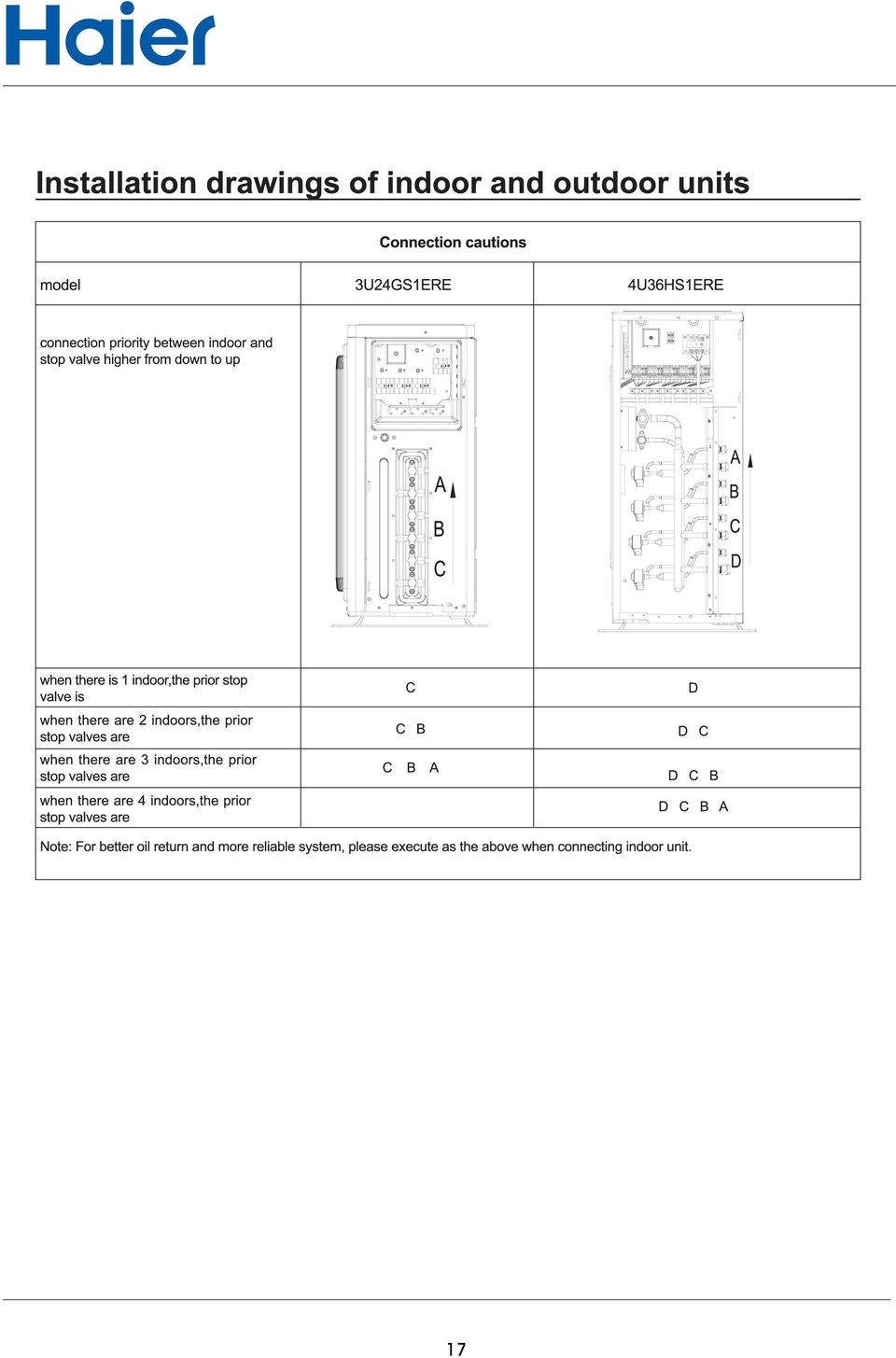
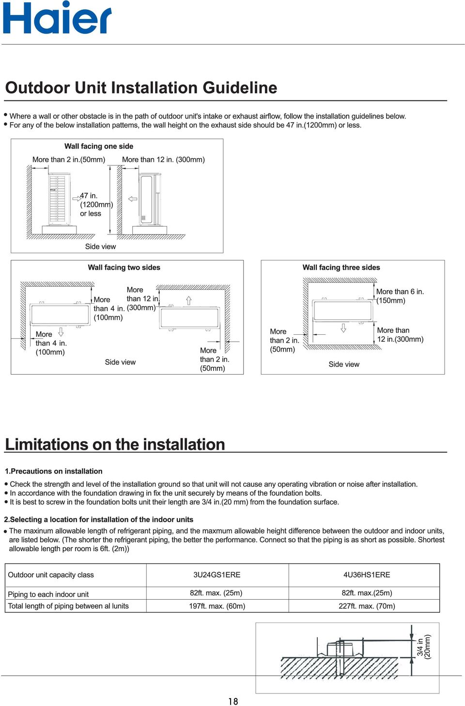
15 8. Installation 13

16 14

17 15

18 16

19 17
20 18
21 19
22 ) 20
23 21
24 22
25 . 23
26
27 25
28 9. Dip switch setting, outdoor unit PC photo, and function 9.1 Dip swith setting and Outdoor unit PC photo Model PC Power module Filter board 3U24GS1ERE 4U36HS1ERE Dip switch setting Outdoor main PC dip switch setting S5 definition Decription ON Cooling only OFF Heating pump(default) --- ON set ON if frost easily --- OFF set OFF if hard to frost(default) ON Max.running current is 15A OFF Normal control(default) OFF ON OFF U ON OFF ON U ON --- temperature correction valid OFF --- temperature correction null(default) ON Quiet operation valid OFF Quiet o poperationeration vaild(default) S6 : outdoor central control address setting outdoor central control address OFF OFF OFF OFF 1 OFF OFF OFF ON 2 OFF OFF ON OFF 3 ON ON ON ON 16 S7: pre-set dip switch Small service PC: dip switch setting S1 definition: Definition OFF OFF OFF OFF State when out of factory ON OFF OFF Compulsive heating: 50Hz, outdoor motor 5-class, standard open angle 200, the OFF others are rmal OFF ON OFF Compulsive cooling: 60Hz, outdoor motor 7-class, standard open angle 200, the OFF others are rmal OFF OFF ON OFF Rated operation OFF OFF OFF ON Time defrost valid ON ON ON ON Detection for wrong wiring 26
29 PC( ) S06 PC ( ) S05 S06 27
30 Power module( ) Power module( ) 28
31 Filter board( ) 29
32 Dip switch setting Outdoor main PC dip switch setting S5 definition Decription ON Cooling only OFF Heating pump(default) --- ON set ON if frost easily --- OFF set OFF if hard to frost(default) ON Max.running current is 15A OFF Normal control(default) OFF ON OFF U ON OFF ON U ON --- temperature correction valid OFF --- temperature correction null(default) ON Quiet operation valid OFF Quiet o poperationeration vaild(default) S6 : outdoor central control address setting outdoor central control address OFF OFF OFF OFF 1 OFF OFF OFF ON 2 OFF OFF ON OFF 3 ON ON ON ON 16 S7: pre-set dip switch Small service PC: dip switch setting S1 definition: Definition OFF OFF OFF OFF State when out of factory ON OFF OFF Compulsive heating: 50Hz, outdoor motor 5-class, standard open angle 200, the OFF others are rmal OFF ON OFF Compulsive cooling: 60Hz, outdoor motor 7-class, standard open angle 200, the OFF others are rmal OFF OFF ON OFF Rated operation OFF OFF OFF ON Time defrost valid ON ON ON ON Detection for wrong wiring 30
33 9.2 Outdoor unit control Outdoor frequency control A. Compressor running frequency range: 20~95RPS Electronic expansion valve (EEV) control A: EEV specification Max. open angle Driving speed 500 pulse PPS : Start-up control In Cool/Dry mode, standard open angle: outdoor ambient temp. 68 O F, 250 pulse(e);outdoor ambient temp.<68 O F, 210 pulse(e); In Heat mode, standard open angle: outdoor ambient temp. 50 O F, pulse (E);outdoor ambient temp.<50 O F, 210 pulse (E). E: In order to cooperate the compressor discharging temp. over high protection, the system will enlarge the EEV open angle. ithin 5 minutes after compressor starts up, it will t modify. The detecting period is 30 seconds. Cooling mode Indoor modification angle 212 O F<discharging temp. +50 degree/30seconds, it will stop until up to the max. permitted opening angle 194 O F< discharging temp.<=212 O F EEV hold control <=194 O F -5 degree/30seconds, and reduce to 0 degree gradually Heating mode Indoor modification angle 212 O F<discharging temp. +50 degree/30seconds, it will stop until up to the max. permitted opening angle 212 O F< discharging temp.<=212 O F Keep the angle <=194 O F -5 degree/30seconds, and reduce to 0 degree gradually way valve control in heating Protection when 4-way valve can t reverse in heating: 10 minutes later after compressor startup, if indoor coil average temp. is below 59 O Fand keeps for 1 minute, the unit will stop and occur the 4-way valve protection. compressor ON OFF 4-way valve ON OFF 15 S(E ) 2 minutes and 55s 31
34 9.2.4 Electric heater control If compressor has t run for a long time, the refrigerant will remain on the bottom of compressor and mix with the refrigeranr oil. hen re-startup, because low pressure reduces, refrigerant will be migrated from the refrigerant oil and cause foam in the oil, this can cause oil be pumped out of compressor. Therefore please stop heating the compressor bottom to ensure the low pressure in startup period should t go down greatly. Ambient temp. TA 80.6 O F, when compressor stops, the electric heater will be electrified. hen TA 89.6 O F, or compressor running, the electric heater will be off Control of defrosting in heating In heating mode, defrosting temp. sensor will check the frosting condition of outdoor heat exchanger and make defrosting control. A: Enter condition: a. In heating mode, if the compressor has run for 10 minutes contiusly and run for 45 minutes in all, the system will measure the defrosting temperature sensor Te and outdoor ambient temp. sensor TA, if the below condition can be met for contius 5 minutes, the unit will enter defrosting operation: Te C TA-α Herein: C: TA<32 O F=0.8 TA 32 O F, C=0.6 According to S5-2, the setting is as follow: in the place easy to frost, it is H; when out of factory, it is M. Jumper selection M(out of factory) H Heater ON OFF Ambient temp. TA( ) α( O F) 8(E) 6(E) b. Defrosting entering condition: 5 O F C TA-α 28.4 O F; c. Stop and Pause condition of compressor running accumulative time in heating mode: Checking Stop: running operation changes from heating to cooling. Checking Pause: thermostat OFF, or the unit stops. Cancel condition: It will take the max. 10 minutes from beginning defrosting to quit it. Te sensor will measure the condition of outdoor heat exchanger, if the temp. is over 44.6 O F for 60 seconds in all or is up to 53.6 O F for 30 seconds in all, the defrosting will be over Compulsory defrosting control Enter condition: in heating mode, after receiving the compulsory defrosting signal from indoor unit, the unit will perform the compulsory defrosting operation. Cancel condition: Te 53.6 O F and keep for 1 minute or the defrosting time is over 10 minutes. The manual defrosting signal of indoor unit will remain until the outdoor enters defrosting mode. Note: hen outdoor compressor t running, the unti still can enter manual defrosting, but it will comply with the 3-minute protection of compressor. 32
35 9.2.6 Defrosting operation flow chart: beginning end fixed frequency indicated FQY 60s defrosting FQY 80 Hz(E ) 60s soft startup compressor 0HZ 0HZ 5s outdoor motor ON send defrosting signal to indoor Auto OFF 4-way valve ON OFF 15s 450-pulse 450-pulse 350-pulse(E) all EEVs auto open angle auto open angle all indoor motors ON OFF anti-cold air fun ction 33
36 9.2.7 Frequency control when compressor discharge temp.(td) is too high Purpose: make compressor frequency control if the discharging temp. is too high, to lower the discharging temp. efficiently and ensure the system can run rmally. Multi: Discharging temp. TD If keeping for 10s, the unit stops, 3 minutes later, the unit can re-startup. If in 60 minutesthe unit occurs alarm for 3 times, the failure can be eliminated. Reduce FQY rapidly 2HZ/S Reduce FQY rapidly 1HZ/S Reduce FQY slowly 1HZ/10S Remain FQY Increase FQY slowly 1HZ/10S 34
37 I 0.95I 0.93I 0.90I 0.88I 0.85I Stop immediately, if abrmal stop 3 times in 1 hour, the unit will stop and alarm. Reduce FQY rapidly 2HZ/S Reduce FQY rapidly 1HZ/S Reduce FQY slowly 1HZ/10S Remain FQY Increase FQY slowly 1HZ/10S hen the input signal of pressure switch is low level: 0 for 1 minute, that shows high pressure code to indoor. Meanwhiel, by controling the max. condensating temp.tc(cooling) or module temp. sensor(tmave), please confirm as follow Condensing temp Keep for 5 seconds, stop to alarm, after 3-minute standby, the unit can restartup. In 60 minutes it occurs 3 times contiusly, unit will stop to alarm and the failure can be resumed after being electrified again. Reduce FQY rapidly 2HZ/S Reduce FQY rapidly 1HZ/S Reduce FQY slowly 1HZ/10S Remain FQY 140 Increase FQY slowly 1HZ/10S (1) hen compressor is running, if output signal of low pressure switch is low level: 0 for 1 (2) hen compressor running, if output signal of low pressure switch is low level: 0 for 30 35
38 hen unit stops, the reason that system still checks the low pressure : in a long time stop, make protection for the compressor on the condition of great refrigerant leakage. The reason that low pressure switch action time is 30 seconds: when compressor stops, low pressure does t change, so it will be shorter than the set time in operation. (3) hen compressor starts up, in 8 minutes, low pressure switch signal will be shielded. (4) In defrosting, low pressure switch will be shielded. (5) In oil return procedure, low pressure switch will be shielded. (6) In the refrigerant discharging procedure after the oil return in cooling is over, low pressure switch will be shielded. In addition, the system will control low pressure through the evaporator temp. TE to realize the low pressure protection function. In cooling, confirm through Tc2AVE: -13 Normal operation TinAVE Min. running FQY 20HZ SV2 OFF & 20HZ SV2 ON & 20HZ Keep for 5 seconds, unit stops and alarm occurs. 3 minutes later, restart up. If it occurs 3 times in 1 hour, it will always alarm and stop, electrify again and failure will be cleared. In heating, confirm through defrosting temp. Te: Te Normal operation Min. running FQY 20HZ SV2 OFF & 20HZ SV2 ON & 20HZ Keep for 5 seconds, unit stops and alarm occurs. 3 minutes later, restart up. If it occurs 3 times in 1 hour, it will always alarm and stop, electrify again and failure will be cleared. If the failure is t confirmed as the permanent protection, outdoor will t send failure code to indoor, and indoor will t alarm. 36
39 10. Diagstic code 3U24GS1ERE 4U36HS1ERE PRODUCT DIAGNOSIS PROCEDURE Malfunction Diagsis Code 1 Faulty of outdoor unit EEPROM 2 IPM overcurrent or short circuit 4 Communication failure between Module and ECU 5 Module operated overload 6 8 Module low or high voltage Discharging temperature overheating.lack of refrigerant, ambient temperature too high or PMVs blocked. 9 Malfunction of the DC fan motor 10 Malfunction of defrosting temp. sensor 11 Malfunction of compressor suction temp. sensor 12 Malfunction of ambient temp. sensor 13 Malfunction of compressor discharge temp. sensor 15 Communication failure between indoor&outdoor unit 16 Lack of refrigerant or discharging 17 4-way valve switching failure 18 Loss of synchronism detection 20 Indoor thermal overload 21 Indoor frosted Module thermal overload Compressor start failure Module input overcurrent 26 MCU reset Module input current detect circuit malfunction Malfunction of liquid pipe temp. sensor for indoor unit A 29 Malfunction of liquid pipe temp. sensor for indoor unit 30 Malfunction of liquid pipe temp. sensor for indoor unit C 31 Malfunction of liquid pipe temp. sensor for indoor unit D 32 Malfunction of gas pipe temp. sensor for indoor unit A Malfunction Code Diagsis using the Numeral Light Indicator Diagsis Malfunction of gas pipe temp. sensor for indoor unit Malfunction of gas pipe temp. sensor for indoor unit C Malfunction of gas pipe temp. sensor for indoor unit D Malfunction of gas pipe temp. sensor for indoor unit E Precautions For Adding Refrigerant 1.This system must use refrigerant R410A. 2.Add refrigerant 20g per meter when the total piping length exceeds the standard value,but make sure that the total liquid piping length should be less than the max value. 38 Malfunction of module temp.sensor Momentary power failure detection Malfunction of condensing temp. sensor Malfunction of liquid pipe temp. sensor for indoor unit E Malfunction of Toci temp. sensor Outdoor Unit Std. Value Max Value 3U24GS1ERE 30m/98ft. 60m/197ft. 4U36HS1ERE 40m/131ft. 70m/227ft. 42 System high pressure switch off 43 System low pressure switch off 44 System high pressure protection.refrigerant overabundance,high condensing temp. or malfunction of fan motor. 45 System low pressure protection.refrigerant shortage, Low defrosting temp., or malfunction of fan motor. Definition of S1 on Malfunction Display Definition OFF OFF OFF OFF ON OFF OFF OFF OFF ON OFF OFF OFF OFF ON OFF Rated Operating OFF OFF OFF ON Time Defrost Valid State when out of factory (Normal Operating) Compulsive Heating:Frequency 50HZ; PMV 200 pulse;class 5 of outdoor fan motor. Compulsive Cooling:Frequency 60HZ; PMV 200 pulse;class 7 of outdoor fan motor. Notes: 1.hen using this product,you need t to set the address.ut the L/N wires between indoor & outdoor units must be corresponded,or there will be communication failure. 2.Quiet Operation Setting.Set the DIP 8 to ON position of S5,the system will run with lower ise,but the max capacity will also reduce slightly. 3.Do NOT change the settings of other switchs,wrong settings can make the system damage or other malfunctions. 4.For some malfunctions, this system can make back up running. * ECU:Electronic Control Unit * MCU:Micro Control Unit * PMV:Pulse Modulated Valve
40 11. Trouble shooting Trouble 1: No display on the operation panel start check if display panel and the unit matched well replace display panel and check again yes if the red diode and green diode on indoor PC flash in turn if the power terminal block is 220V input check the terminal block and the power supply yes yes PC is faulty, replace it check if display panel is 12V power supply check if power wiring is in open circuit check if fuse is burnt PC is faulty, replace yes yes yes display panel circuit is damaged, replace it replace power wiring and check again replace the fuse and check again Trouble 2: Sensor failure start as per the wiring diagram,check the connection between sensor and PC is correct yes re-fix the sensor and check again check if sensor is in open circuit or PC port is t in good condition check if sensor resistor value is correct replace sensor and check again yes yes replace sensor and check again PC is faulty and repalce it, check again 38
41 Trouble 3: Communication failure between indoor and outdoor start as per the wiring diagram, check if communication wiring is correct re-wiring, and check again yes check if the communication port connecting to the indoor/outdoor PC is in open circuit if the power cable and the communication wire are too close, resulting in the wrong commission data PC is faulty, replace and check again yes yes replace the communication connection wire, check again adjust the distance and check again Trouble 4: Indoor PC EEPROM data is wrong 1.If the failure occurs when being electrif ied for the first time, that shows EEPROM (8-bit pin) t fixed firmly or damaged. 2.If the failure occurs when running, that shows EEPROM is faulty and need to be replaced. Trouble 5: Indoor repeated unit number 1.Firstly query the unit number: switch off the unit, press SLEEP for about 15 seconds until the buzzer sounds 5 times, on the display panel there will be digit, which is indoor numbe r. y this method,you can check if there is repeated unit number, if yes, please re-set the number as per the unit number setting procedure. 2.Re-set the unit number directly, the unit with outdoor pipe A is No. 1; the unit with outdoor pipe is No. 2; the unit with pipe C is No.3 Trouble 6: Indoor fan motor failure, AC fan motor has t 50Hz zero-crossing detection start check if the fan motor input connection is fixed badly(cn3 on PC) check the fan motor feedback wire is fixed badly (CN23 on PC) PC is faulty and replace it yes replace fan motor input port, cut off power supply and be electrified again yes replace fan motor feedback port, cut off power supply and be electrified again Trouble 7: Outdoor unit failure Check the failure code on outdoor indicator board (5-lamp) 39
42 Trouble 8: Outdoor unit alarms sensor failure start as per the wiring diagram, check if connection port between sensor and PC is correct yes check if the sensor is in open circuit or the connection port to PC is in good condition yes replace sensor and check again re-fix the sensor and check again check if the sensor resistor value is correct yes PC is faulty and repalce it, check again replace sensor and check again Trouble 9: AC current over current protection or current transducer damaged, or compressor blocked rotor, compressor great vibration, compressor abrmal startup, state detecting curcuit abrmal or compressor damaged. The former twice failure can be resumed automatically, if outdoor board occurs this failure always, and can t be resumed for a long time, that shows: 1. Power module (SPDU) damaged, please replace the power module, then re-wiring as per the wiring diagram (70% possibility) 2. Short circuit in power board results in the power module damaged (15% possibility) 3. Damaged compressor results in this failure (10 % possibility) 4. Main control board is faulty, replace it (5 % possibility) Trouble 10: High pressure failure Reasons: 1. Over high system pressure results that the unit stop, and the compressor protection will work. The failure can be resumed. 2. Pressure switch wire is t fixed well or in open circuit. start check if the connector between pressure switch and PC is fixed badly or damaged check if the 2 straight lugs on the pressure switch are in good condition if outdoor fan motor cant startup rmally in cooling mode replace main control board and check again yes replace pressure switch connector, shut off and be electrified again, re-check yes replace pressure switch connector, shut off and be electrified again, re-check yes check if the outdoor motor has power input replace outdoor motor and check again 40
43 Failure 11: Low pressure switch failure Reason: 1. Too low system pressure causes that the unit stops and the compressor protection works, the failure can be resumed. 2. Pressure switch wire is t fixed well or in open circuit. start check if the connector between pressure switch and PC is fixed badly or damaged (CN20 on PC) yes replace pressure switch connector, shut off and be electrified again, re-check check if the 2 straight lugs on the pressure switch work badly yes replace pressure switch connector, shut off and be electrified again, re-check if indoor fan motor cant startup rmally in heating mode(except for defrost) yes check if the indoor motor has power input replace main control board and check again replace indoor motor and check again 41
44 Appendix Sensor characteristic Model Function Part code Characteristic 3U24GS1ERE 4U36HS1ERE gas liquid sensot Oil temp.sensor Defrost temperature sensor power module temp.sensor R77=10KΩ±3% 25/50=3700K±3% R77=10KΩ±3% 25/50=3700K±3% R77=10KΩ±3% 25/50=3700K±3% R122=17K±2% 25/50=4170K±3% 42
45 R77=10KΩ±3% 25/50=3700K±3% T( ) Rm(KΩ) T( ) Rm(KΩ) T( ) Rm(KΩ) T( ) Rm(KΩ)
46 R122=17K±2%25/50=4170K±3% T( ) Rm(KΩ) T( ) Rm(KΩ) T( ) Rm(KΩ) T( ) Rm(KΩ)
Appendix - Controllers 179
 Version: 200703 Appendix - Controllers 179 -3- -4- -5- -6- -7- -8- 2. Specifications 2.1 Specifications for inverter units item Model AB182ACERA Function cooling heating Capacity kw 5.01.8--5.8 5.22.0---6.2
SERVICE MANUAL. Room Air Conditioner Multi Split type Outdoor unit /R410A DC Inverter/
 SERVICE MANUAL Room Air Conditioner Multi Split type Outdoor unit /R410A DC Inverter/ FS2MI-147HFD FS2MI-187HFD FS3MI-217HFD FS3MI-277HFD FS4MI-277HFD FS4MI-367HFD FS5MI-367HFD NOTE: Before servicing the
Indoor coil is too warm in cooling mode or too cold in heating mode. Reversing valve or coil thermistor is faulty
 Codes Room Air Conditioner range: Indoor unit alarm s If timer lamp flashes for 1 second on, 1 second off, this indicates pre heating on the coil during heating mode and is not an error. If timer lamp
Technical service manual 2009
 MULTI SPLIT TYPE, HEAT PUMP AIR CONDITIONERS Technical service manual 2009 KSIM MULTI ZONE SERIES R410A DC Inverter multi Series Models KSIM20912-H216 KSIM30912-H216 KSIM40912-H216 CONTENT 1. Product features
SERVICE INSTRUCTION R410A. WALL MOUNTEDtype INVERTER SPLIT TYPE ROOM AIR CONDITIONER. Models Indoor unit Outdoor unit
 SERVICE INSTRUCTION SPLIT TYPE ROOM AIR CONDITIONER WALL MOUNTEDtype INVERTER Models Indoor unit Outdoor unit ASYG07LECA ASYG09LECA ASYG12LECA ASYG14LECA AOYG07LEC AOYG09LEC AOYG12LEC AOYG14LEC R410A CONTENTS
LG Air Conditioning Multi F(DX) Fault Codes Sheet. Multi Split Units
 Fault Codes Sheet. Multi Split Units") Multi Split Units If there is a fault on any LG Multi unit, an Error mark is indicated on the display window of the indoor unit, wired-remote controller, and LED s of outdoor unit control board. A two
Multi Split Units If there is a fault on any LG Multi unit, an Error mark is indicated on the display window of the indoor unit, wired-remote controller, and LED s of outdoor unit control board. A two
Service manual. Website: www.andico.com.au CAUTION - BEFORE SERVICING THE UNIT, READ THE SAFETY - PRECAUTIONS IN THIS MANUAL.
 Website: www.andico.com.au Service manual CAUTION - BEFORE SERVICING THE UNIT, READ THE SAFETY - PRECAUTIONS IN THIS MANUAL. - ONLY FOR AUTHORISED SERVICE PERSONNEL. MODELS: MPK1-09CR-QB8 MPK1-12ER-QB6
LG Air Conditioning - Universal Split Fault Codes Sheet. Universal Split Systems
 Universal Split Systems If there is a fault on any LG Universal unit, a two digit number will appear on the remote controllers led display. If the unit does not have a remote controller the fault will
Failure code manual. content
 Failure code manual content 一 wall split AC series 2 二 floor standing AC series. 4 三 portable AC series.. 5 四 dehumidifer 6 五 DC inverter single split series...7 六 DC inverter multi-split series 10 1 一
SERVICE INSTRUCTION R410A. WALL MOUNTEDtype SPLIT TYPE ROOM AIR CONDITIONER INVERTER. Models Indoor unit Outdoor unit AOU 9RLFW AOU12RLFW AOU15RLS
 SERVICE INSTRUCTION SPLIT TYPE ROOM AIR CONDITIONER WALL MOUNTEDtype INVERTER Models Indoor unit Outdoor unit ASU 9RLF ASURLF ASU5RLS AOU 9RLFW AOURLFW AOU5RLS R40A CONTENTS. DESCRIPTION OF EACH CONTROL
HP switch LP switch Discharge thermo Comp. Surface thermo
 1 Specifications Zubadan Model Name PUHZ-SHW80VHA PUHZ-SHW11VHA PUHZ-SHW11YHA Power supply (phase, cycle, voltage) 1φ, V, Hz 1φ, V, Hz 3φ, 0V, Hz Max. current A 9.5 35.0 13.0 Breaker size A 3 16 Outer
Service manual. The voltage in P3 and P4 in outdoor PCB is high voltage about 310V The voltage in P5 and P6 in outdoor PCB is high voltage about 310V
 Resistance The voltage in P3 and P4 in outdoor PCB is high voltage about 310V The voltage in P5 and P6 in outdoor PCB is high voltage about 310V 9.2 Troubleshooting for indoor unit E0 E1 E2 E3 E5 E6 P0
13. Troubleshooting. Indoor unit s LED indication of Corona DC inverter unit. Indoor unit s LED indication of Alfa DC inverter unit
 Troubleshooting 13. Troubleshooting Indoor unit s LED indication of Corona DC inverter unit MCAC-HTSM-2007-11 E0 E1 E2 E3 E5 E6 P0 P1 P2 P3 P5 EEPROM error outdoor communication error Zero-crossing examination
CONTENTS 1. IMPORTANT NOTICE 2 2. TECHNICAL SPECIFICATION 3 3. OPERATION DETAILS 4 4. ELECTRICAL SCHEMATIC DIAGRAM 13 5. EXPLOSION VIEW 16 6
 TCL WALL MOUNTED SPLIT-TYPE AIR CONDITIONERS SERVICE MANUAL No.TE080528 Models KFTHP-12 KFTHP-18 KFTHP-24 CONTENTS 1. IMPORTANT NOTICE 2 2. TECHNICAL SPECIFICATION 3 3. OPERATION DETAILS 4 4. ELECTRICAL
SERVICE MANUAL MUZ-GE09NA MUZ-GE12NA MUZ-GE15NA MUZ-GE18NA MUZ-GE24NA MUY-GE09NA MUY-GE12NA MUY-GE15NA MUY-GE18NA MUY-GE24NA OUTDOOR UNIT
 SPLIT-TYPE AIR CONDITIONERS Revision B: Descriptions regarding the outdoor fan motor have been corrected. Please void OBH549 REVISED EDITION-A. OUTDOOR UNIT SERVICE MANUAL HFC utilized R410A. OBH549 REVISED
SERVICE INSTRUCTION R410A. SPLIT TYPE ROOM AIR CONDITIONER Universal Floor / Ceiling Duct / Cassette Wall Mounted / Floor type INVERTER MULTI
 SERVICE INSTRUCTION SPLIT TYPE ROOM AIR CONDITIONER Universal Floor / Ceiling Duct / Cassette Wall Mounted / Floor type INVERTER MULTI R410A Models Indoor unit Outdoor unit AB*14LBAJ AB*18LBAJ AB*F14LAT
DC INVERTER MULTI-SYSTEM AIR CONDITIONER
 TECHNICAL & SERVICE MANUAL OUTDOOR UNIT : AEMI0AH AEMIAHB AEMIAH AEMI0AH FILE NO. Destination: Europe DC INVERTER MULTI-SYSTEM AIR CONDITIONER Capacity.0k.k.k.0k Outdoor Model No. AEMI0AH AEMIAHB AEMIAH
CONTENTS 1. IMPORTANT NOTICE 2 2. TECHNICAL SPECIFICATION 3 3. OPERATION DETAILS 4 4. WIRING DIAGRAM 11 5. EXPLOSION VIEW 12 6.
 TCL WALL MOUNTED SPLIT-TYPE AIR CONDITIONERS SERVICE MANUAL No.TE051220 Models TAC-09CHSA/GI TAC-12CHSA/GI CONTENTS 1. IMPORTANT NOTICE 2 2. TECHNICAL SPECIFICATION 3 3. OPERATION DETAILS 4 4. WIRING DIAGRAM
14. Troubleshooting Guide
 14. Guide 14.1 Refrigeration Cycle System In order to diagnose malfunctions, ensure the air conditioner is free from electrical problems before inspecting the refrigeration cycle. Such problems include
TAS-18MVHN/O TAS-27MVHN/O TAS-36MVHN/O
 SERVICE MANUAL AIRCONDITIONER DC INVERTER MULTI TYPE TAS-18MVHN/O TAS-27MVHN/O TAS-36MVHN/O DC MULTI OUTDOOR UNITS CONTENTS 1. General information of Outdoor Units... 3 2. Dimensions... 4 3. Wiring Diagram...
technical data air conditioning systems RXS20-25-35E (single phase) FBQ-B8V1-B8V3B Split Heat Pump Condensing Units Split Sky Air
 FBQ-B8V1-B8V3B Split Heat Pump Condensing Units Split Sky Air") technical data RXS20-25-35E FBQ-B8V-B8V3B (single phase) Split Heat Pump Condensing Units air conditioning systems Split Sky Air Outdoor Units R-40A RXS-E2VB Split Sky Air Outdoor Units Features O u t
technical data RXS20-25-35E FBQ-B8V-B8V3B (single phase) Split Heat Pump Condensing Units air conditioning systems Split Sky Air Outdoor Units R-40A RXS-E2VB Split Sky Air Outdoor Units Features O u t
Technical service manual
 GD Midea Refrigeration Equipment Co.,Ltd ODMI-A-1202 MULTI SPLIT TYPE, HEAT PUMP AIR CONDITIONERS Technical service manual R410A Multi DC inverter 220~240V-1Ph-50Hz Outdoor units Models M2OC-14HRDN1 M2OC-14HRDN1-Q
PANASONIC TROUBLE SHOOTING GUIDE
 A General Guide To Room Style Products Pipework Pipe sizes and lengths should be as the relevant Technical Guide Both lines should be insulated No line accessories or oil traps should be fitted In cooling
1 4. 3 4-2 ABNORMAL OPERATION. 4-2-1 Error code Display. Specifics Error Code. Subsection Error Code. Subsection and Specifics Error code target
 4-2 ABNORMAL OPERATI 4-2-1 An is represented by 3 digit characters. The first 2 digit means the subsection, and the last 1 digit means the specifics. Ex.) Indoor unit Network communication Error Subsection
R22. K Control. Indoor Unit. Nomenclature. Compatibility PL H 3 G K H B. Unit style Heat Pump Horse Power
 R22. K Control. Indoor Unit. Nomenclature. PL H 3 G K H B Compatibility Unit style Heat Pump Horse Power Control Boost Heaters R22. K Control. Outdoor Unit. Nomenclature. PU H 3 Y K A Compatibility Outdoor
543-0032-00, 943-0032-00. User s Manual
 543-0032-00, 943-0032-00 User s Manual 1 Comfort Alert Diagnostics Faster Service And Improved Accuracy The Comfort Alert diagnostics module is a breakthrough innovation for troubleshooting heat pump and
SERVICE MANUAL MUZ-FE09NA MUZ-FE12NA MUZ-FE18NA OUTDOOR UNIT. No. OBH543 REVISED EDITION-A. Models HFC
 SPLIT-TYPE AIR CONDITIONERS Revision A: MUZ-FE18NA has been added. Please void OBH543. OUTDOOR UNIT SERVICE MANUAL HFC utilized R410A. OBH543 REVISED EDITION-A Models MUZ-FE09NA MUZ-FE12NA MUZ-FE18NA Indoor
SERVICE MANUAL MUZ-GE25VA - E1 MUZ-GE25VAH - E1 MUZ-GE35VA - E1 MUZ-GE35VAH - E1 MUZ-GE42VA - E1 MUZ-GE42VAH - E1 MUZ-GE50VA - E1 MUZ-GE50VAH - E1
 SPLIT-TYPE AIR CONDITIONERS Revision A: MUZ-GE42/50VA(H) - E1 has been added. Please void OBH516. OUTDOOR UNIT SERVICE MANUAL HFC utilized R410A. OBH516 REVISED EDITION-A Models MUZ-GE25VA - E1 MUZ-GE25VAH
SERVICE MANUAL SPLIT SYSTEM ROOM AIR CONDITIONER SHARP CORPORATION SHARP CORPORATION CONTENTS
 SERVICE MANUAL SPLIT SYSTEM ROOM AIR CONDITIONER INDOOR UNIT AH-129 AH-MP14 OUTDOOR UNIT AU-129 AU-MP14 CONTENTS SPECIFICATIONS...2 EXTERNAL DIMENSIONS...4 WIRING DIAGRAMS...5 ELECTRICAL PARTS...6 MICROCOMPUTER
Model: AC-S13CG x 2. Model No: AC-S13CGx2.doc Version 1.0
 Air Conditioner Service Manual 2 3 Model: AC-S13CG x 2 3 Content Technical specification.. 4 Performance curve.5 Outline & dimension of indoor unit..10 Outline & dimension of outdoor unit 11 Exploded view
Midea Commercial Air Conditioner Malfunction Handbook
 Midea Commercial Air Conditioner Malfunction Handbook May 1, 2008 Customer Service Philosophy of Midea Air Conditioner Service Target: 100% Customer Satisfaction Service Standard: 100% Earnestness Service
SERVICE MANUAL OUTDOOR UNIT. No. OBH590 REVISED EDITION-B. Models HFC
 SPLIT-TYPE AIR CONDITIONERS Revision B: MUZ-EF25/35/42/50VE - E2 and MUZ-EF25/35VEH - E2 have been added. Please void OBH590 REVISED EDITION-A. OUTDOOR UNIT SERVICE MANUAL HFC utilized R410A. OBH590 REVISED
DC INVERTER MULTI-SYSTEM AIR CONDITIONER
 TECHNICAL & SERVICE MANUAL OUTDOOR UNIT : CM97 CM7 CM7 FILE NO. Destination: North America DC INVERTER MULTI-SYSTEM AIR CONDITIONER Capacity at 0V 9,700 BTU/h,00 BTU/h 0,600 BTU/h Outdoor Model No. CM97
york air-conditioning products Residential & VRF News 2015
 york air-conditioning products Residential & VRF News 2015 york air-conditioning products Catalogue Content Split Systems Pag. High wall High Efficiency Inverter YWHJZH 09 to 24 K 6 High wall Inverter
SERVICE MANUAL OUTDOOR UNIT MUZ-A09NA,- 1,- U1,- U2 MUZ-A12NA,- U1 MUZ-A15NA,- U1 MUZ-A17NA,- U1 MUY-A15NA MUY-A17NA MUY-A24NA,- 1,- U1,- U2
 SPLIT-TYPE AIR CONDITIONERS Revision E: MUZ-GA24NA and MUY-GA24NA have been added. Please void OB451 REVISED EDITION-D. OUTDOOR UNIT SERVICE MANUAL HFC utilized R410A. OB451 REVISED EDITION-E Models MUZ-A09NA,-
New Deluxe Wall Mounted Heat Pump Series EXTERIOS
 New Deluxe Wall Mounted Heat Pump Series EXTERIOS May 2013 New Deluxe Wall Mounted Heat Pump Series Panasonic Adding New Air Conditioner Lineup Setting Another Mile Stone in the US Ductless Split History
INVERTER WALL MOUNTED TYPE ROOM AIR-CONDITIONER ( Split system, air to air heat pump type )
") Manual No. 06. SRK-T. 050 updated September 29, 2009 INVERTER WALL MOUNTED TYPE ROOM AIR-CDITIER ( Split system, air to air heat pump type ) SRK20ZD-S1, SRK25ZD-S1, SRK35ZD-S1, SRK50ZD-S1 SRK63ZE-S1, SRK71ZE-S1
Manual No. 06. SRK-T. 050 updated September 29, 2009 INVERTER WALL MOUNTED TYPE ROOM AIR-CDITIER ( Split system, air to air heat pump type ) SRK20ZD-S1, SRK25ZD-S1, SRK35ZD-S1, SRK50ZD-S1 SRK63ZE-S1, SRK71ZE-S1
DC INVERTER MULTI-SYSTEM AIR CONDITIONER
 AIR CONDITIONER AIR CONDITIONER TECHNICAL & SERVICE MANUAL INDOOR UNIT : CS-MKE7NKU CS-MKE9NKU CS-MKE12NKU CS-MKE18NKU CS-MKE24NKU DC INVERTER MULTI-SYSTEM AIR CONDITIONER Capacity 7,500BTU / h 9,000BTU
DC INVERTER SPLIT SYSTEM AIR CONDITIONER
 TECHNICAL & SERVICE MANUAL CSKE1NB41 & CZ18BT1U + CUKE1NK1 CSKE18NB4UW & CZ18BT1U + CUKE18NKU DC INVERTER SPLIT SYSTEM AIR CONDITIONER Indoor Model No. Body (Panel) CSKE1NB41 (CZ18BT1U) CSKE18NB4UW (CZ18BT1U)
DC INVERTER SPLIT SYSTEM AIR CONDITIONER
 AIR CONDITIONER TECHNICAL & SERVICE MANUAL CS-KS30NKU + CU-KS30NKUA CS-KS36NKU + CU-KS36NKUA DC INVERTER SPLIT SYSTEM AIR CONDITIONER Indoor Model No. CS-KS30NKU CS-KS36NKU Product Code No. 852 360 86
SERVICE MANUAL REFRIGERATION
 SERVICE MANUAL REFRIGERATION ELECTROLUX HOME PRODUCTS S.p.A. Publication no. Spares Operations Italy 599 36 16-90 Corso Lino Zanussi, 30 031117 I - 33080 PORCIA / PN (ITALY) ITZ/SERVICE/AA Fax +39 0434
sip Sanyo Modbus Guide Technical Specification Pinouts, Cable Connections & Wiring Issue 2: February 2009 Synapsys Solutions Ltd, all rights reserved
 Sanyo Section : Section : Section : Section : Section : sip Modbus Guide Configuration Modbus Table Technical Specification Pinouts, Cable Connections & Wiring Alarm Fault Codes Issue : February 009 Section
SERVICE MANUAL FOR 6535 SERIES TWO TON HIGH EFFICIENCY PACKAGED HEAT PUMPS
 SERVICE MANUAL FOR 6535 SERIES TWO TON HIGH EFFICIENCY PACKAGED HEAT PUMPS TABLE OF CONTENTS 1. Warnings...2 2. Accessibility Of Appliance...3 3. Unit Dimensions And Specifications...3 4. Unit Specifications
A/C-HEATER SYSTEM - AUTOMATIC
 A/C-HEATER SYSTEM - AUTOMATIC 1995 Volvo 850 1995-96 Auto. A/C-Heater Systems Volvo 850 * PLEASE READ THIS FIRST * WARNING: To avoid injury from accidental air bag deployment, read and carefully follow
MP-4000 Alarm List (Software version 2.4.3 or later)
") Service Bulletin SUBJECT: MP4000 Alarm s BULLETIN: C 100 DATE: June 19, 2013 ALARM LIST Where it is possible the alarm number is kept the same as for MP-3000. MP-3000 holds alarm number from 0 to 127.
Service Bulletin SUBJECT: MP4000 Alarm s BULLETIN: C 100 DATE: June 19, 2013 ALARM LIST Where it is possible the alarm number is kept the same as for MP-3000. MP-3000 holds alarm number from 0 to 127.
SERVICE MANUAL. Room Air Conditioner Multi Split Wall-Mounted Type Indoor. FSAI-Pro-91AE2 FSAI-Pro-121AE2 FSAIF-Pro-181AE2
 SERVICE MANUAL Room Air Conditioner Multi Split Wall-Mounted Type Indoor FSAI-Pro-91AE2 FSAI-Pro-121AE2 FSAIF-Pro-181AE2 NOTE: Before servicing the unit, please read this at first. Always contact with
Air Conditioners Technical Data
 Air Conditioners Technical Data O u t d o o r U n i t E E D E N 2-0 0 RX-JV Outdoor Unit RX-JV TABLE OF CONTENTS RX-JV Features............................................................. 2 2 Specifications.......................................................
CLOSE CONTROL SYSTEM. PFD series provide you with highly reliable computer room cooling system. High Reliability
 PFD-P250VM-E PUHY-P250YJM-A(-BS) PUHY-P500YSJM-A(-BS) PQHY-P250YHM-A CLOSE CONTROL SYSTEM MITSUBISHI ELECTRIC s Close Control System (PFD series) is specifically designed for computer rooms, laboratories
FILE NO. SVM-07013 11. HOW TO DIAGNOSE THE TROUBLE
 FILE. SVM-070. HOW TO DIAGSE THE TROUBLE The pulse motor circuits are mounted to both indoor and outdoor units. Therefore, diagnose troubles according to the trouble diagnosis procedure as described below.
How To Measure Temperature On A Thermostat
 Кондиционеры Mitsubishi Heavy Техническое руководство Кондиционеры настенного типа SRK20HD-S, SRK28HD-S, SRK40HD-S, SRK20CD-S, SRK28CD-S, SRK40CD-S CTENTS 1. GENERAL INFORMATI... 1 1.1 Specific features...
Multi Air Conditioner SVC MANUAL(Exploded View)
") Internal Use nly http://biz.lgservice.com Multi Air Conditioner SVC MANUAL(Exploded View) MDEL : A5UW306FA3 CAUTIN Before Servicing the unit, read the safety precautions in Standard SVC manual. nly for
Internal Use nly http://biz.lgservice.com Multi Air Conditioner SVC MANUAL(Exploded View) MDEL : A5UW306FA3 CAUTIN Before Servicing the unit, read the safety precautions in Standard SVC manual. nly for
AUTOMATIC CONTROL HEATING, VENTILATION AND AIR CONDITIONING SYSTEM
 SECTION 7D AUTOMATIC CONTROL HEATING, VENTILATION AND AIR CONDITIONING SYSTEM TABLE OF CONTENTS Description and Operation... 7D- General... 7D- FATC Control... 7D- FATC Input/Output Routing Diagram...
Simple Self-Diagnosis by Malfunction Code
 Simple Self-Diagnosis by Code After Sales Service Division (SM-TS2) Detail Division 0 Indoor Unit System Others A C E F H J L P U M 7 8 9 External device activated (unified) Protection devices activated
Split and Multi Split air conditioners Service information
 Split and Multi Split air conditioners Service information Programming LG wired controllers 2 New type 2 Old type 7 Fault codes 9 Wall units (single split) 9 Universal split and multi split 10 Detailed
DESIGN & TECHNICAL MANUAL
 AIR CONDITIONER Wall Mounted type DESIGN & TECHNICAL MANUAL INDOOR AS G07LECA AS G09LECA AS G12LECA AS G14LECA OUTDOOR AO G07LEC AO G09LEC AO G12LEC AO G14LEC 1. INDOOR UNIT : AS G07LECA AS G09LECA AS
Split System Cooling Product Data
 Split System Cooling Product XL16i 1½ 5 Tons PUB. NO. 22-1890-01 Features and Benefits Climatuff compressor Efficiency up to 16.0 SEER and 9.0 HSPF All aluminum Spine Fin coil WeatherGuard fasteners Quick-Sess
Split System Heat Pump Product Data
 Split System Heat Pump Product Silver 14 4A6H4 1 1 /2-5 Tons PUB. NO. 12-1175-07 Contents Features and Benefits 2 Model Nomenclature 3 General 4 Product Specifications 4 A-weighted Sound Power Level [db(a)]
SERVICE MANUAL INDOOR UNIT
 SPLIT-TYPE AIR CONDITIONERS Revision E: MSZ-GE22VAD- A1 has been added. Please void OBH531 REVISED EDITION-D. INDOOR UNIT SERVICE MANUAL. OBH531 REVISED EDITION-E Models MSZ-GE22VA - A1 MSZ-GE50VA - A1
Room Air Conditioner SVC MANUAL(Exploded View)
") Internal Use Only http://biz.lgservice.com Room Air Conditioner SVC MANUAL(Exploded View) MODEL : LSN092CE(ASNC0914DH0)/LSN092HE(ASNH091E1H0) LSU092CE(ASUC0914DH0)/LSU092HE(ASUH091E1H0) LSN122CE(ASNC121E1H0)/LSN122HE(ASNH121E1H0)
Internal Use Only http://biz.lgservice.com Room Air Conditioner SVC MANUAL(Exploded View) MODEL : LSN092CE(ASNC0914DH0)/LSN092HE(ASNH091E1H0) LSU092CE(ASUC0914DH0)/LSU092HE(ASUH091E1H0) LSN122CE(ASNC121E1H0)/LSN122HE(ASNH121E1H0)
DUCTLESS MINI-SPLITS SINGLE & MULTI-ZONE HORIZONTAL AIR CONDITIONERS PORTABLE UNITS FREE MATCH COMPONENTS
 DUCTLESS MINI-SPLITS SINGLE & MULTI-ZONE HORIZONTAL AIR CONDITIONERS PORTABLE UNITS FREE MATCH COMPONENTS AN EXCELLENT CHOICE IN COOLING, COMFORT AND CONVENIENCE Why choose a Mini-Split system? Installing
Haier Air conditioner
 For Europe Haier Air conditioner HAND in HAND HIGHER and HIGHER Page:1 For Europe HSU-09/12HVA103/R2(DB) HSU-09/12RHA103/R2(DB) Page:2 Error Codes and Description indoor and outdoor display(1) indoor Code
evo+ Installation, Service & Troubleshooting DUCTLESS SYSTEM
 evo+ DUCTLESS SYSTEM Installation, Service & Troubleshooting Models: GWH09AB-A3DNA2B GWH12AB-A3DNA2B GWH09AB-D3DNA2D GWH12AB-D3DNA2D GWH18AB-D3DNA2D GWH24AB-D3DNA2D Table of Contents Safety Precautions
SERVICE MANUAL INDOOR UNIT
 SPLIT-TYPE AIR CONDITIONERS Revision B: "How to check miswiring and serial signal error" for MUZ type has been added. The description about "Low standby power control" has been added to "TECHNICAL CHANGES".
WYS SERIES SPLIT 3D DC INVERTER HEAT PUMP / AIR CONDITIONER SERVICE MANUAL
 z WYS SERIES SPLIT 3D DC INVERTER HEAT PUMP / AIR CONDITIONER SERVICE MANUAL Revision A: 151110001, Content updated. Model Numbers: 17 SEER Family: WYS009AMFI17RL, WYS012AMFI17RL, WYS009GMFI17RL, WYS012GMFI17RL,
Portable Air Conditioner
 Portable Air Conditioner Owner's Manual Model:3 in 1 12,000 Btu/h Series 3 Please read this owner s manual carefully before operation and retain it for future reference. CONTENTS 1. SUMMARY...1 2. PORTABLE
ECOCIAT. Domestic hot water heat recovery unit
 Heat recovery unit Domestic hot water High energy efficiency with R410A Compact and quiet Scroll compressors Brazed-plate heat exchangers Heating Heat recovery ENVIRONMENTALLY HFC R410A PROTECTION DE FRIENDLY
Technical Information
 Date of last update: Oct-11 Ref: D7.8.4/1011/E Application Engineering Europe CORESENSE DIAGNOSTICS FOR STREAM REFRIGERATION COMPRESSORS CoreSense Diagnostics for Stream Refrigeration Compressors... 1
User s Information/Installation Instructions
 Outdoor Heat Pump User s Information/Installation Instructions 13 SEER R-410A High Efficiency Split System These units have been designed and tested for capacity and effi ciency in accordance with A.R.I.
Repair Guideline for TCL DC Inverter Air Conditioner
 Repair Guideline for TCL DC Inverter Air Conditioner FLOS SERIE---V3 0 CONTENTS Ⅰ. Introduction of New control board for outdoor unit...2 1. The structure of control board... 2 2. Diagram of outdoor unit........4
INSTALLATION OPERATING & MAINTENANCE MANUAL
 INSTALLATION OPERATING & MAINTENANCE MANUAL Basic Climatic TM Controller Ecologic English November 2002 CONTENTS PAGE GENERAL DESCRIPTION 3 USER INTERFACE 4 The keypad incorporated on the unit 4 The keypad
Si10-417_C. Pocket Manual. Service Diagnosis SPLIT & MULTI
 Pocket Manual Service Diagnosis SPLIT & MULTI Service Diagnosis SPLIT & MULTI 1. Troubleshooting with LED...5 1.1 Indoor Unit... 5 1.2 Outdoor Unit... 10 2. Troubleshooting by Symptoms...11 2.1 Air conditioner
DC INVERTER SPLIT SYSTEM AIR CONDITIONER
 TECHNICAL & SERVICE MANUAL CSKS12NB41 & CZ18BT1U + CUKS12NK1A CSKS18NB4UW & CZ18BT1U + CUKS18NKU CSKS18NB4UW & CZ18BT1U + CUKS18NKUA DC INVERTER SPLIT SYSTEM AIR CONDITIONER Indoor Model No. Body (Panel)
COOLSIDE box R410A. conditioned server - racks for direct installation into the room INVERTER E C
 COOLS conditioned server - racks for direct installation into the room COOLSIDE box INVERTER R410A E C 2 COOLSIDE box GENERAL FEATURES COOLSIDE BOX is a split system consisting of an outdoor motocondensing
HEATER, AIR CONDITIONING AND VENTILATION
 55-1 GROUP 55 HEATER, AIR CONDITIONING AND VENTILATION CONTENTS GENERAL DESCRIPTION 55-2 HEATER AND AIR CONDITIONING SYSTEM 55-4 HEATER CONTROL 55-6 A/C-ECU 55-7 A/C COMPRESSOR 55-9 CONDENSER 55-9 DUCT
SECTION 15750 PACKAGED ROOFTOP AIR CONDITIONING UNITS
 SECTION 15750 PART 1 - GENERAL 1.01 DESCRIPTION A. Section includes requirements for roof mounted, self-contained units, with electric cooling, and electric or reverse refrigeration cycle (heat pump) heating
Technical Service Manual. Version One
 [Gree Central Air Conditioner] Technical Service Manual Ducted type unit 2.3KW-16KW Version One GREE ELECTRIC APPLIANCES.INC.OF ZHUHAI - 1 - FG Series wind pipe blowing air-conditioning unit Section One:
Table Z. Troubleshooting Chart for Air Conditioners. Cause
 Troubleshooting Chart for Air Conditioners Type of Unit Complaint Cause With open-type compressor Electric motor will not start Power failure Check circuit for power source Compressor stuck Locate cause
DM13-01.01.01en. Service manual MIV V5 HEAT PUMP DC INVERTER R410A MVUH252B-VA3 MVUH280B-VA3 MVUH335B-VA3 MVUH400B-VA3 MVUH450B-VA3 MVUH500B-VA3
 DM13-01.01.01en Service manual MIV V5 HEAT PUMP DC INVERTER R410A MVUH252B-VA3 MVUH280B-VA3 MVUH335B-VA3 MVUH400B-VA3 MVUH450B-VA3 MVUH500B-VA3 Contents Part 1 General Information... 1 Part 2 Selection
HITACHI INVERTER-DRIVEN MULTI-SPLIT SYSTEM HEAT PUMP AIR CONDITIONERS
 HITACHI INVERTER-DRIVEN MULTI-SPLIT SYSTEM HEAT PUMP AIR CONDITIONERS SET FREE FSG(1)/FS3, FS5 SERIES AND SET FREE FXG/FX3 SERIES Models In-the-Ceiling Type RPI-0.8FSG1 RPI-2.5FSG1 RPI-8FSG1
Application Engineering
 Application Engineering February 2011 Electronic Unit Controller Table of Contents 1. Introduction and Features... 2 1.1 Technical Specifi cations... 3 1.2 Pressure Probe Error Bypass... 3 1.3 Bump Start...
ROOFTOP - HEAT PUMP UNIT. This document applies when installing into an air handler or as part of an air handling system.
 ROOFTOP - HEAT PUMP UNIT Technical data Applies to Model YNRA R410A This document applies when installing into an air handler or as part of an air handling system. CONTENTS 1. General description... 2
Condensing unit type EPSILON-ECHOS LE Technical information manual
 Condensing unit type EPSILON-ECHOS LE Technical information manual 2 > EPSILON ECHOS Water chiller > EPSILON ECHOS /HP Reversible heat pump > EPSILON ECHOS /ST Water chiller with storage tank and pumps
TECHNICAL DATA & SERVICE MANUAL SPLIT SYSTEM AIR CONDITIONER INDOOR UNIT: AW52AL AW64AL AW52AL 387030095 AW64AL 0.8180.463.0 07/05
 TECHNICAL DATA & SERVICE MANUAL INDOOR UNIT: AW52AL AW64AL SPLIT SYSTEM AIR CONDITIONER Model No. Product Code No. AW52AL 387030095 AW64AL 387030096 0.8180.463.0 07/05 IMPORTANT! Please read before installation
SERVICE MANUAL. Domestic Air Conditioner. Model. Feature HW-05LN03
 Domestic Air Conditioner SERVICE MANUAL Model HW-05LN03 Feature Anti-mold filter Mechanical control Easy clean filters Slide chassis 4-way airflow direction 2 cool settings, 2 fan settings Serial Number:
Air Conditioning System
 Air Conditioning System 1 Chonan Technical Service Training Center Chonan Technical Service Training Center 2 Objectives To understand the components of air conditioning system. To understand the control
Repair Guideline for SANYO New Erp. DC Inverter Air Conditioner (Published in May, 2013)
") Repair Guideline for SANYO New Erp DC Inverter Air Conditioner (Published in May, 2013) Contents I. Electronic Control of DC Inverter Air Conditioner 2 1. Main parts of the electronic control of DC inverter
Repair Guideline for SANYO New Erp DC Inverter Air Conditioner (Published in May, 2013) Contents I. Electronic Control of DC Inverter Air Conditioner 2 1. Main parts of the electronic control of DC inverter
Roof Top Air Conditioner INSTALLATION AND OPERATING INSTRUCTIONS
 Roof Top Air Conditioner INSTALLATION AND OPERATING INSTRUCTIONS Ducted System RECORD THIS UNIT INFORMATION FOR FUTURE REFERENCE: Model Number: Serial Number: Date Purchased: This manual must be read and
USER S MANUAL HSC-24A
 AIRREX AIR CONDITIONER USER S MANUAL HSC-24A Thank you for purchasing an AIRREX AIR CONDITIONER. BEFORE operation please read this user s manual carefully. Keep this manual readily available. It is ESSENTIAL
REMOTE CONTROL MANUAL
 REMOTE CONTROL MANUAL ENGLISH CONTENT PRECAUTIONS...1-2 USING THE REMOTE CONTROL UNIT...3 OPERATION...4-9 Thank you for purchasing our Room Air Conditioner. Before using your air-conditioner, please read
ALL IN ONE. Heat Pump Water Heater
 ALL IN ONE Heat Pump Water Heater INSTALLATION AND OPERATION INSTRUCTIONS Please read this user s manual carefully before operate the unit. www.airtradecentre.com CONTENTS A. IMPORTANT REMARKS ------------------------------------------------------------------------------------------------
Hitachi Air Conditioning. Engineered for tomorrow. Room Air Conditioning GENERAL CATALOGUE
 Hitachi Air Conditioning Engineered for tomorrow. Room Air Conditioning GENERAL CATALOGUE Contents Page 04 Product Range 08-09 RAC Summit Wall Mounted 10 RAC Shirokuma Wall mounted 11 RAC S Series - Wall
How To Wire Wire Wire A Power Supply On A Powerline (Powerline) From A Powerstation To A Powerplant (Powerplant) (Powerplant) (Control Board) (Wire) (Switchboard) (Wired) (
 From A Powerstation To A Powerplant (Powerplant) (Powerplant) (Control Board) (Wire) (Switchboard) (Wired) (") SERVICE MANUAL Order No.AC0S020V0 Wall mounted Type DC Inverter EA-Series Model No. HSU09VHJ(DB) WARNING This service information is designed for experienced repair technicians only and is not designed
SERVICE MANUAL Order No.AC0S020V0 Wall mounted Type DC Inverter EA-Series Model No. HSU09VHJ(DB) WARNING This service information is designed for experienced repair technicians only and is not designed
DERON Air/Water Swimming pool Heat Pump. CY/DY series for Heating/Cooling. Description
 Description Compact air/water heat pump for outside installation. With suction gas cooled rotary compressor. With extensive aluminium/cu lamellar tube evaporator and PVC Titanium condenser. Axial fan Refrigerant
SERVICE MANUAL INDOOR UNIT MSZ-EF35VEW MSZ-EF22VEB - - E1 MSZ-EF25VEB E1 MSZ-EF35VEB - - E1 MSZ-EF35VEB E1 MSZ-EF35VES - E1 - E1 MSZ-EF22VEW -
 SPLIT-TYPE AIR CONDITIONERS Revision A: Airflow in the Silent mode in the cooling operation has been changed. "TROUBLESHOOTING" has been corrected. Please void OBH589. INDOOR UNIT SERVICE MANUAL. OBH589
SERVICE MANUAL. Model No. HSU24VHJ(DB) Wall mounted Type DC Inverter EA-Series WARNING. Haier Group. Order No.AC1101S021V0
 Wall mounted Type DC Inverter EA-Series WARNING. Haier Group. Order No.AC1101S021V0") SERVICE MANUAL Order No.AC1101S021V0 Wall mounted Type DC Inverter EA-Series Model No. HSU24VHJ(DB) WARNING This service information is designed for experienced repair technicians only and is not designed
SERVICE MANUAL Order No.AC1101S021V0 Wall mounted Type DC Inverter EA-Series Model No. HSU24VHJ(DB) WARNING This service information is designed for experienced repair technicians only and is not designed
TSB #: 74 Date: 9/7/2013 HOLDEN VE/WM HVAC & A/C DIAGNOSTIC HINTS
 HOLDEN VE/WM HVAC & A/C DIAGNOSTIC HINTS TSB #: 74 Date: 9/7/2013 Initial Once Read: In this technical bulletin we have listed diagnostic advice relating to the Holden VE/WM HVAC & A/C system. This information
Doc.No. NDP 192U-02. Electric Pump Controller CE-124P. Instruction Manual
 Doc.No. NDP 192U-02 Electric Pump Controller CE-124P Instruction Manual 1. Parts Name and Function 1) POWER LED Indicate that CE-124P is powered up. 2) START/STOP KEY (SELECTOR KEY) Used to start and stop
Service Facts. WARNING: HAZARDOUS VOLTAGE - DISCONNECT POWER and DISCHARGE 4TTM3-SF-1. Split System Cooling 4TTM3018-4TTM3060
 4TTM3-SF-1 Service Facts Split System Cooling 4TTM3018-4TTM3060! CAUTION UNIT CONTAINS R-410A REFRIGERANT! R-410A OPERATING PRESSURE EXCEEDS THE LIMIT OF R-22. PROPER SERVICE EQUIPMENT IS REQUIRED. FAILURE
*.ppt 11/2/2009 12:48 PM 1
 Digital Compressor Controller *.ppt 11/2/2009 12:48 PM 1 Copeland Scroll Digital Controller Simple Controller That Enables OEM s To Use Digital Scrolls Relieves OEM From Developing Special Controllers
Hot Water. Heat pump water heaters. Residential and Commercial R410a
 Hot Water Heat pump water heaters Residential and Commercial R410a Heat pump technology Heat Pump Water Heating is a new idea using existing technology and is viewed as the latest generation of water heating