IEC Type Test Report Report No. EU1522-H-00.1 PH4 Series Polymer-housed Arrester 20,000 A Line Discharge Class 4
|
|
|
- Amanda Reeves
- 8 years ago
- Views:
Transcription
1 IEC Type Test Report Report No. EU1522-H-00.1 PH4 Series Polymer-housed Arrester 20,000 A Line Discharge Class 4 This report records the results of type tests made on PH4 series 20 ka Line Discharge Class 4 arresters, rated up to 420 kv. Tests were performed in accordance with procedures of IEC Standard , Ed. 2.1, 2006, Surge arresters - Part 4: Metal-oxide surge arresters without gaps for a.c. systems. To the best of our knowledge and within the usual limits of testing practice, tests performed on these arresters demonstrate compliance with the relevant clauses of the referenced standard. M. G. Comber Manager, Engineering Date: 4/12/2007 Separate reports provide details of each test, according to the following table: Report No. Description Clause Issue date EU1522-H-01.1 Insulation Withstand Test on Arrester Housing /12/2007 EU1522-H-02.1 Residual Voltage /12/2007 EU1522-H-03.1 Long Duration Current Withstand /12/2007 EU1522-H-04.1 Accelerated Aging Procedure /12/2007 EU1522-H-05.1 Heat Dissipation Behavior of Test Section /12/2007 EU1522-H-06.1 Switching Surge Operating Duty /12/2007 EU1522-H-07.1 Short Circuit /12/2007 EU1522-H-08.1 Internal Partial Discharge /12/2007 EU1522-H-09.1 Bending Moment /12/2007 EU1522-H-10.1 Seal Leak Rate /12/2007 EU1522-H-11.1 RIV /12/2007 EU1522-H-12.1 Moisture Ingress /12/2007 EU1522-H-13.1 Weather Ageing /12/2007 EU1522-H-14.1 Power Frequency Voltage Versus Time Annex D 4/12/2007

2 EU1522-H-01.1 IEC Type Test Report Report No. EU1522-H-01.1 PH4 Series Polymer-housed Arrester 20,000 A Line Discharge Class 4 Insulation Withstand Test on Arrester Housing This report records the results of type tests made on PH4 series 20 ka Line Discharge Class 4 arresters, rated up to 420 kv. Tests were performed in accordance with procedures of IEC Standard , Ed. 2.1, 2006, Surge arresters - Part 4: Metal-oxide surge arresters without gaps for a.c. systems. To the best of our knowledge and within the usual limits of testing practice, tests performed on these arresters demonstrate compliance with the relevant clauses of the referenced standard. M. G. Comber Manager, Engineering Date: 4/12/2007 1

3 EU1522-H-01.1 IEC TYPE TEST REPORT Insulation Withstand Test on Arrester Housing TESTS PERFORMED: Insulation withstand tests were made on one arrester unit with internal components removed, in accordance with the requirements of clause of IEC It is required that the external insulation withstand of the arrester housing conforms to the following: Lightning impulse withstand voltage in dry conditions shall not be less than the lightning impulse protective level of the arrester unit multiplied by 1.3. Switching impulse withstand voltage in wet conditions shall not be less than the switching impulse protective level of the arrester unit multiplied by Power frequency withstand voltage (peak value) in wet conditions shall not be less than the switching impulse protective level of the arrester unit multiplied by 1.06 for a duration of 1 min. RESULTS: The PH4 series of arresters use four different housing lengths, all of the same individual weathershed geometry. The insulation withstand tests were performed on a sample constructed with the longest housing. The highest U c used in this housing is 120 kv, for which the lightning impulse protective level is 377 kv at 20kA., and the maximum switching impulse protective level is 304 kv at 2kA. Lightning impulse The lightning impulse test was performed under dry conditions by applying 15 positive and 15 negative full-wave lightning-impulse voltages to the test sample. The impulse voltages had a virtual front time of 1.2 µs (±30%) and a virtual time to half value of 50 µs (±20%). The test sample withstood all impulses without disruptive discharge. The withstand voltages obtained were corrected to standard atmospheric conditions in accordance with IEC The required minimum lightning impulse withstand voltage is 1.3 times the maximum lightning impulse protective level, or 1.3 x 377 = 490 kv. Switching impulse The switching impulse test was performed under wet conditions by applying 15 positive and 15 negative full-wave switching-impulse voltages to the test sample. The precipitation conditions and resistivity of the water were in accordance with the requirements of IEC The impulse voltages had a time to crest value of 250 µs (±20%) and a time to half value of 2500 µs (±60%). The test sample withstood all impulses without disruptive discharge. The withstand voltages obtained were corrected to standard atmospheric conditions in accordance with IEC The required minimum switching impulse withstand voltage is 1.25 times the maximum switching impulse protective level, or 1.25 x 304 = 380 kv. 2

4 EU1522-H-01.1 Power frequency The power frequency test was performed under wet conditions by applying a 60 Hz voltage for a duration of 1 min. The precipitation conditions and resistivity of the water were in accordance with the requirements of IEC The test sample withstood the applied voltage without disruptive discharge. The required minimum power frequency withstand voltage is 1.06 times the maximum switching impulse protective level, or 1.06 x 304 = 323 kvpeak. Tests were successfully performed at levels higher that exceeded the minimum levels indicated above. Results are summarized in Table 1. Withstand test Lightning impulse, pos Lightning impulse, neg Switching impulse, pos Switching impulse, neg Table 1. Measured and corrected withstand values Uncorrected withstand voltage kv pk Atmospheric conditions Correction factors Corrected Ambient Air Absolute Air Humidity withstand temperature pressure humidity density o C KPa gm -3 k 1 k 2 kv peak Wet test Wet test Hz Wet test

5 EU1522-H-02.1 IEC Type Test Report Report No. EU1522-H-02.1 PH4 Series Polymer-housed Arrester 20,000 A Line Discharge Class 4 Residual Voltage This report records the results of type tests made on PH4 series 20 ka Line Discharge Class 4 arresters, rated up to 420 kv. Tests were performed in accordance with procedures of IEC Standard , Ed. 2.1, 2006, Surge arresters - Part 4: Metal-oxide surge arresters without gaps for a.c. systems. To the best of our knowledge and within the usual limits of testing practice, tests performed on these arresters demonstrate compliance with the relevant clauses of the referenced standard. M. G. Comber Manager, Engineering Date: 4/12/2007 1

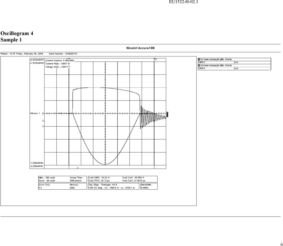
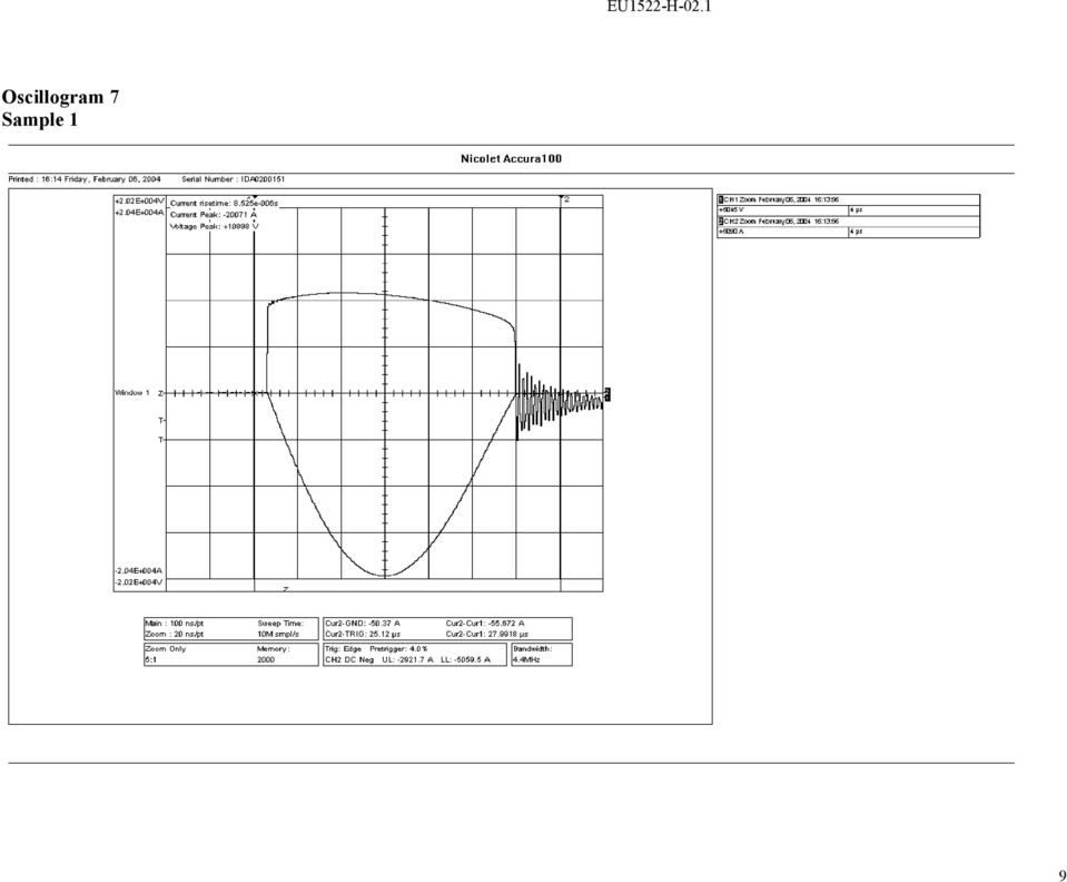
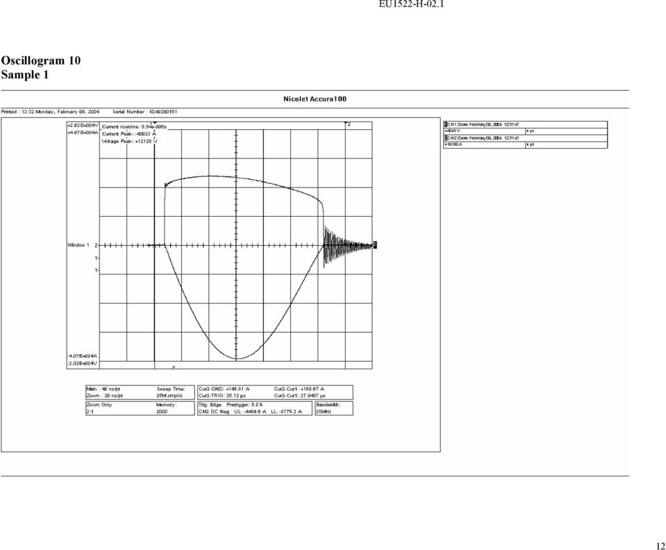
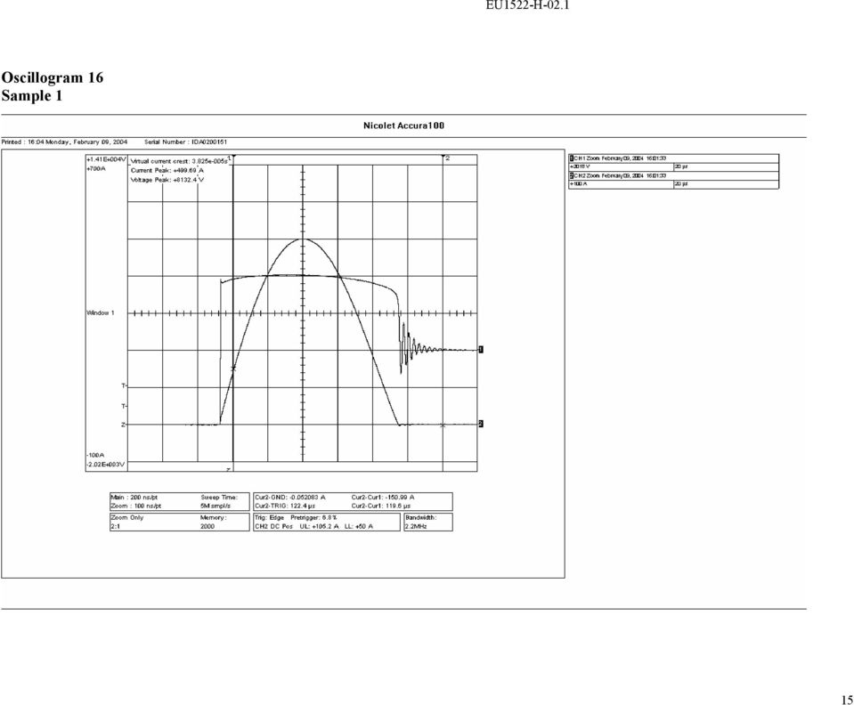
6 EU1522-H-02.1 IEC TYPE TEST REPORT Residual Voltage TESTS PERFORMED: Residual voltage measurements were made on three single resistor elements. Tests were conducted in accordance with clause of IEC , to determine steep current impulse residual voltages at 20 ka, lightning impulse residual voltages at 10 ka, 20 ka and 40 ka, and switching impulse residual voltages at 0.5 ka and 2 ka. Oscillograms of current and voltage were obtained for each test. For each test sample, all measured voltages have been rationalized to the lightning impulse residual voltage of that sample at nominal discharge current (20 ka 8/20), and the results have been displayed in graphical form. RESULTS: Tables 1, 2 and 3 show the residual voltages measured on test samples 1, 2 and 3, respectively. For each test sample, the measured residual voltages have been expressed in per unit of the lightning impulse residual voltage at nominal discharge current (20 ka, 8/20). Table 1. Measurements made on test sample 1 Test Wave Current magnitude Waveshape Residual Voltage Oscillogram ka _s kv p.u. number Steep current 20 1/ Lightning 20 8/ impulse Switching /84 impulse Table 2. Measurements made on test sample 2 Current Test wave magnitude Waveshape Residual Voltage Oscillogram ka _s kv p.u. number Steep current 20 1/ Lightning 20 8/ impulse Switching /84 impulse
, and the results have been")
7 EU1522-H-02.1 Table 3. Measurements made on test sample 3 Current Test wave magnitude Waveshape Residual Voltage Oscillogram ka _s kv p.u. number Steep current 20 1/ Lightning 20 8/ impulse Switching /84 impulse The results are shown graphically in the following chart. 1.2 Residual voltage - p.u Switching impulse Steep front Lightning impulse Current - ka The values shown in this chart are all normalized to the lightning impulse residual voltage at nominal discharge current (20 ka). These values (Per-unit U res-chart ) are used to calculate the residual voltage characteristics (U res-arrester ) of assembled H4 series arresters. For the cases of switching impulse and lightning impulse residual voltages, the arrester residual voltages are calculated as follows: U res-arrester = Per-unit U res-chart x U res-nom 3
.")
8 EU1522-H-02.1 where Ures-nom is the published maximum lightning impulse residual voltage of the arrester, as verified by routine test at time of arrester manufacture. For the case of steep current impulse residual voltage, the arrester residual voltage is calculated as follows: U res-arrester = Per-unit U res-chart x U res-nom + L h I n / T f where L is the inductivity per unit length (= 1 µh/m) h is the length of the arrester (excluding the resistors since resistor inductance is already included in the test measurements) I n is the nominal discharge current (= 20 ka) T f is the front time of the steep current impulse (= 1µs) 4
 h is the length of the arrester (excluding the resistors since resistor")
9 EU1522-H-02.1 Oscillograms 5

10 EU1522-H-02.1 Oscillogram 4 Sample 1 6
11 EU1522-H-02.1 Oscillogram 5 Sample 2 7

12 EU1522-H-02.1 Oscillogram 6 Sample 3 8

13 EU1522-H-02.1 Oscillogram 7 Sample 1 9
14 EU1522-H-02.1 Oscillogram 8 Sample 2 10

15 EU1522-H-02.1 Oscillogram 9 Sample 3 11

16 EU1522-H-02.1 Oscillogram 10 Sample 1 12
17 EU1522-H-02.1 Oscillogram 11 Sample 2 13

18 EU1522-H-02.1 Oscillogram 12 Sample 3 14

19 EU1522-H-02.1 Oscillogram 16 Sample 1 15
20 EU1522-H-02.1 Oscillogram 17 Sample 2 16

21 EU1522-H-02.1 Oscillogram 18 Sample 3 17
22 EU1522-H-02.1 Oscillogram 22 Sample 1 18
23 EU1522-H-02.1 Oscillogram 23 Sample 2 19
24 EU1522-H-02.1 Oscillogram 24 Sample 3 20
25 EU1522-H-02.1 Oscillogram 28 Sample 1 21
26 EU1522-H-02.1 Oscillogram 29 Sample 2 22
27 EU1522-H-02.1 Oscillogram 30 Sample 3 23
28 EU1522-H-03.1 IEC Type Test Report Report No. EU1522-H-03.1 PH4 Series Polymer-housed Arrester 20,000 A Line Discharge Class 4 Long Duration Current Impulse Withstand Tests This report records the results of type tests made on PH4 series 20 ka Line Discharge Class 4 arresters, rated up to 420 kv. Tests were performed in accordance with procedures of IEC Standard , Ed. 2.1, 2006, Surge arresters - Part 4: Metal-oxide surge arresters without gaps for a.c. systems. To the best of our knowledge and within the usual limits of testing practice, tests performed on these arresters demonstrate compliance with the relevant clauses of the referenced standard. M.G. Comber Manager, Engineering Date: 4/12/2007
29 EU1522-H-03.1 IEC TYPE TEST REPORT Long Duration Current Impulse Withstand Tests TESTS PERFORMED: Long duration current impulse withstand tests were performed on three test samples, each consisting of two resistors in series. The resistors were selected to represent the lowest acceptable reference voltage level. The tests were conducted in accordance with clause of IEC Prior to the administering of line discharges, measurements were made of the residual voltage and reference voltage on each test sample. The transmission line parameters conformed to the requirements for Line Discharge Class 4 in Table 5 of IEC Table 1 below lists the measured residual voltage and reference voltage for each sample, and lists the corresponding transmission line parameters used for the test. U c for the PH4 series of arresters has been established as 0.78 times the lowest acceptable reference voltage in routine tests, and U r has been established as 1.25 times U c. This would normally be represented in the type test by assigning the test sample U c equal to 0.78 x U ref of the test sample, and test sample U r at 1.25 times this value. However, in this particular test, U c was set at a higher value than that used in the actual design (specifically, x U ref ), thereby making the test more onerous. The minimum energy required for each line discharge for Class 4 arresters is determined from the following formula given in Clause of IEC W = U res x (U L U res ) x 1/Z x T where U res is the switching impulse residual voltage at 500 A. Table 1. Parameters for Line Discharge Tests Parameter Sample 1 Sample 2 Sample 3 Switching impulse residual voltage (kv) U res Initial Residual Voltage 20 ka, 8/20 Reference Current (ma) I ref Reference Voltage (kv c ) V ref COV ( kv rms) U c Rating (kv rms) U r Arrester Classification (ka) Line Discharge Class Virtual Duration of Peak (µs, 90-90%) - min Surge Impedance (Ω) Z g - max (0.8 U r ) Charging Voltage (kv) U L min (2.6 U r ) Energy required (kj) - min Each sample was subjected to 18 line discharges, administered in six groups of three discharges. Within each group of three discharges, the time interval between discharges was 50 to 60 seconds. The samples were allowed to cool to ambient temperature between groups of discharges
30 EU1522-H-03.1 RESULTS: A short circuit test was performed on the generator to confirm that generator impedance and duration of the current discharge met the requirements listed in Table 1. The oscillogram of Figure 1 shows Z g = 8,092 V / A = Ω Virtual Duration of Peak = 2899 µs Figure 1. Oscillogram of discharge current for generator short circuit set up test Table 2 lists the current and voltage magnitudes and discharge energy measured on each of the 18 discharges on each of the three test samples. Figures 2, 3 and 4 show oscillograms of the first and eighteenth discharges for each of the three samples, respectively. Ambient air temperature at the time of the test was 22 C. Impulse I (A) Table 2. Line Discharge Test Measurements Sample 1 Sample 2 Sample 3 V E V I V I (A) E (kj) (kv) (kj) (kv) (A) (kv) E (kj)
31 EU1522-H-03.1 Sample 1, Discharge 1 Sample 1, Discharge 18 Figure 2. Oscillograms of line discharges for sample 1-4 -
32 EU1522-H-03.1 Sample 2, Discharge 1 Sample 2, Discharge 18 Figure 3. Oscillograms of line discharges for sample 2-5 -
33 EU1522-H-03.1 Sample 3, Discharge 3 Sample 3, Discharge 18 Figure 4. Oscillograms of line discharges for sample 3-6 -
34 EU1522-H-03.1 Subsequent to the completion of the transmission line discharges, the residual voltage at nominal discharge current was re-measured and compared to the initial values for each test sample. Results are summarized in Table 3. The maximum change of residual voltage of the three samples is less than the permissible change of 5 % defined by IEC Table 3. Initial and final residual voltage measurements. Sample Residual voltage (kv) Before After Change % % % Disassembly of the test samples at the end of the electrical tests revealed no evidence of physical damage
35 EU1522-H-04.1 IEC Type Test Report Report No. EU1522-H-04.1 PH4 Series Polymer-housed Arrester 20,000 A Line Discharge Class 4 Accelerated Aging Procedure This report records the results of type tests made on PH4 series 20 ka Line Discharge Class 4 arresters, rated up to 420 kv. Tests were performed in accordance with procedures of IEC Standard , Ed. 2.1, 2006, Surge arresters - Part 4: Metal-oxide surge arresters without gaps for a.c. systems. To the best of our knowledge and within the usual limits of testing practice, tests performed on these arresters demonstrate compliance with the relevant clauses of the referenced standard. M.G. Comber Manager, Engineering Date: 4/12/2007
36 EU1522-H-04.1 IEC TYPE TEST REPORT Accelerated Ageing Procedure TESTS PERFORMED: Accelerated aging tests were performed on two resistor elements. The tests were conducted in accordance with the requirements of clause of IEC (requiring the accelerated ageing procedure of clause to be administered). The test samples were placed in an air oven and energized at a voltage equal to the corrected maximum continuous operating voltage, U ct, for 1000 hours. The temperature of the samples was maintained at 115 C ± 2 C for the duration of the test. Power dissipation was measured on each sample throughout the 1000 h test period. Clause of IEC defines three power dissipation values: P 1ct, measured 1 h to 2 h after the initial voltage application P 2ct, measured after 1000 h P 3ct, the minimum value attained during the 1000 h test period. If P 2ct is equal to or less than 1.1 times P 3ct, then the switching surge operating duty test of Clause of IEC is to be performed on new resistors. Furthermore, if P 2ct is equal to or less than P 1ct, then the rated voltage and continuous operating voltage used for the operating duty test are not subject to any modification. RESULTS: Figure 1 graphically displays the measurements made during the 1000 h test period. Table 1 summarizes the values of P 1ct, P 2ct and P 3ct for each sample. The requirements that P 2ct is equal to or less than 1.1 times P 3ct, and P 2ct is equal to or less than P 1ct are met for both samples. Consequently, no modification needs to be made to the rated voltage and continuous operating voltage in the operating duty test, and the operating duty test can be performed on new resistors. Table 1. Power dissipation values Power dissipation at 2 h Power dissipation at 1000 h Minimum power dissipation Sample Number P 1ct (W) P 2ct (W) P 3ct (W)
37 EU1522-H Temperature 100 Power Dissipation - W Voltage - kvrms Sample 2 Voltage Temperature - C Sample Time - h 0 Figure 1. Power dissipation, voltage and temperature measurements during 1000 h test period - 3 -
38 EU1522-H-05.1 IEC Type Test Report Report No. EU1522-H-05.1 PH4 Series Polymer-housed Arrester 20,000 A Line Discharge Class 4 Heat Dissipation Behaviour of Test Section This report records the results of type tests made on PH4 series 20 ka Line Discharge Class 4 arresters, rated up to 420 kv. Tests were performed in accordance with procedures of IEC Standard , Ed. 2.1, 2006, Surge arresters - Part 4: Metal-oxide surge arresters without gaps for a.c. systems. To the best of our knowledge and within the usual limits of testing practice, tests performed on these arresters demonstrate compliance with the relevant clauses of the referenced standard. M.G. Comber Manager, Engineering Date: 4/12/2007
39 EU1522-H-05.1 IEC TYPE TEST REPORT Heat Dissipation Behaviour of Test Section TESTS PERFORMED: Tests were performed as required by clause and Annex B of IEC , to compare the cooling characteristics of the test section used for type tests with those of a full-size arrester unit. For this purpose, a specially modified arrester unit with U r = 150 kv unit and a test section with U r = 10.6 kv were prepared. The 150 kv rated unit, which represents the highest individual unit rated voltage and the most resistors per unit length of all units used in the arrester design, was equipped with a thermocouple located between one-third and one-half of the unit length from the top of the resistor stack. The test section was comprised of two resistor elements assembled into a short section of porcelain housing, insulated on top and bottom ends to control the rate of cooling to meet the requirements that the test section cools at a rate not greater than that of the assembled unit. A thermocouple was located at the mid-height of the two-resistor stack Both assembled unit and test section were heated electrically with a power frequency overvoltage to raise the average temperature of the resistors to 120 o C in the same amount of time. The voltage was removed and the samples allowed to cool naturally. Temperature measurements were made throughout the cooling period. RESULTS: The resistors in both the assembled unit and the test section were heated by applying a voltage sufficiently above U r to raise the resistor temperature to 120 o C in approximately 4 min. Figure 1 graphically displays the cooling of both samples over a period of approximately 6.5 hours. With both samples starting from the same initial temperature of 120 o C, the temperature of the resistors in the test section remain at or slightly above the temperature of the resistors in the fully assembled unit throughout the cooling period. This demonstrates the validity of the test section for use in type tests involving thermal recovery
40 EU1522-H Temperature - C Arrester unit cooling curve Test section cooling curve Time - min Figure 1. Cooling curves of fully assembled unit and test section - 3 -
41 EU1522-H-06.1 IEC Type Test Report Report No. EU1522-H-06.1 PH4 Series Polymer-housed Arrester 10,000 A Line Discharge Class 4 Switching Surge Operating Duty Test This report records the results of type tests made on PH4 series 20 ka Line Discharge Class 4 arresters, rated up to 420 kv. Tests were performed in accordance with procedures of IEC Standard , Ed. 2.1, 2006, Surge arresters - Part 4: Metal-oxide surge arresters without gaps for a.c. systems. To the best of our knowledge and within the usual limits of testing practice, tests performed on these arresters demonstrate compliance with the relevant clauses of the referenced standard. M.G. Comber Manager, Engineering Date: 4/12/2007
42 EU1522-H-06.1 IEC TYPE TEST REPORT Switching Surge Operating Duty Test TESTS PERFORMED: Switching surge operating duty tests, in accordance with the requirements of clause of IEC , were performed on three prorated test sections. The test sections were prepared based on the results of the tests to verify heat dissipation behaviour of test sample (see EU1522-H-05 section of PH4 type test report). Each section consisted of two resistors in series. The resistors were selected to represent the lowest acceptable reference voltage level. The tests were conducted in accordance with. Prior to the conditioning portion of the test, measurements were made of the lightning impulse residual voltage of each section, and also of reference voltage of each section. Additional measurements were made of power dissipation at U c, and an adjusted value U c was determined such that the power dissipation of each sample represented the maximum power dissipation of resistors that could be used in arrester assembly. The adjusted value Uc was used in the thermal recovery portion of the test. The conditioning portion of the test consisted of two parts. In the first part, a series of twenty 8/20 lightning current impulses were applied to each section, with peak value of the impulses being equal to the nominal discharge current. The series of impulses was divided into four groups of five, with the interval between impulses within each group being between 50 and 60 seconds and the interval between groups being between 25 and 30 minutes. Test sections were energized at 60 Hz voltage of 1.2 U c during the application of the impulses within each group. The impulses were timed to occur 60 before the crest of the 60 Hz voltage with the same polarity of the impulse. In the second part, a series of two 100kA 4/10 impulses were applied to each section, with the section allowed to cool to ambient temperature between impulses. Following the conditioning portion of the test, each section was placed in an oven and heated overnight to 60 ± 3 C. After removal from the oven, each section was subjected to two long duration current impulses, with time between impulses being between 50 and 60 seconds. The parameters of the transmission line used to generate these impulses conformed to the requirements for Line Discharge Class 4 in Table 5 of Clause of IEC Within 100 milliseconds of the second long duration current impulse, rated voltage (U r ) was applied to each section for 10 seconds, immediately followed by the adjusted U c for 30 minutes, during which period the power dissipation was monitored to verify thermal stability. At the end of the above test sequence, each section was allowed to cool to ambient temperature, at which point the lightning impulse residual voltage at nominal discharge current was re-measured
43 EU1522-H-06.1 Table 1 lists the initial measurements of residual voltage and reference voltage for each section, and lists the corresponding transmission line parameters used for the test. U c for the PH4 series of arresters has been established as 0.78 times the lowest acceptable reference voltage in routine tests, and U r has been established as 1.25 times U c. The minimum energy required for each line discharge for Class 4 arresters is determined from the following formula given in Clause of IEC W = U res x (U L U res ) x 1/Z x T where U res is the switching impulse residual voltage at 500 A. Table 1. Initial Measurements and Parameters for Line Discharge Tests Parameter Sample 1 Sample 2 Sample 3 Switching impulse residual voltage (kv) U res Initial Residual Voltage 20 ka, 8/20 Reference Current (ma) I ref Reference Voltage (kv c ) V ref COV ( kv rms) U c Adjusted COV (kvrms) Uc Rating (kv rms) U r Arrester Classification (ka) Line Discharge Class Virtual Duration of Peak (µs, 90-90%) - min Surge Impedance (Ω) Z g - max (0.8 U r ) Charging Voltage (kv) U L min (2.6 U r ) Energy required (kj) - min RESULTS: Representative voltage and current waveforms for lightning impulse conditioning discharges and high current conditioning impulses are shown in Figures 1 and 2, respectively. A short circuit test was performed on the generator to confirm that generator impedance and duration of the current discharge met the requirements listed in Table 1. The oscillogram of Figure 3 shows Z g = 8,092 V / A = Ω Virtual Duration of Peak = 2899 µs Table 2 lists the current and voltage magnitudes and discharge energy measured on each of the two line discharges for each of the three test samples
44 EU1522-H-06.1 Section 1: 5 th conditioning impulse Section 1: 20 th conditioning impulse Figure 1. Representative oscillograms of 20kA 8/20 conditioning impulses - 4 -
45 EU1522-H-06.1 Section 2: 1 st conditioning impulse Section 2: 2 nd conditioning impulse Figure 2. Representative oscillograms of 100kA conditioning impulses - 5 -
46 EU1522-H-06.1 Figure 3. Oscillogram of discharge current for generator short circuit set up test Impulse I (A) Table 2. Line Discharge Test Measurements Section 1 Section 2 Section 3 V V V E (kj) I (A) E (kj) I (A) (kv) (kv) (kv) E (kj) Representative waveforms of voltage and current during for line discharges and the 10 s application of U r are shown in Figure 4. Ambient air temperature at the time of the test was 22 C. Table 3 lists measurements made during this period. Voltage applied during the 10 s was approximately 4% above the rated voltage of the sections
47 EU1522-H-06.1 Figure 4. Oscillogram of second line discharge and application of U r for section 1 Time (s) Table 3. Measurements made during 10 s application of U r. Section 1 Section 2 Section 3 Voltage Current Time Voltage Current Time Voltage (kvc) (mac) (s) (kvc) (mac) (s) (kvc) Current (mac) Avg rms voltage during 10s kv Avg rms voltage during 10s kv Avg rms voltage during 10s kv Figure 5 shows representative oscillograms of voltage and current at the beginning and end of the 30 min application of U c. Table 4 lists measurements of power dissipation made during this period
48 EU1522-H-06.1 Figure 5. Oscillograms of voltage and current at the beginning and end of the 30 min application of U c for section 1-8 -
49 EU1522-H-06.1 Table 4. Measurements of power dissipation made during 30 min at U c Time (min) Power Dissipation (W) Section 1 Section 2 Section Subsequent to the completion of the thermal recovery, and after the sections had cooled to ambient temperature, the residual voltage at nominal discharge current was re-measured and compared to the initial values for each test sample. Results are summarized in Table 5. The maximum change of residual voltage of the three samples is less than the permissible change of 5 % defined by IEC Table 5. Initial and final residual voltage measurements. Section Residual voltage (kv) Initial Final Change % % % Disassembly of the test samples at the end of the electrical tests revealed no evidence of physical damage
50 EU1522-H-07.1 IEC Type Test Report Report No. EU1522-H-07.1 PH4 Series Polymer-housed Arrester 20,000 A Line Discharge Class 4 Short Circuit This report records the results of type tests made on PH4 series 20 ka Line Discharge Class 4 arresters, rated up to 420 kv. Tests were performed in accordance with procedures of IEC Standard , Ed. 2.1, 2006, Surge arresters - Part 4: Metal-oxide surge arresters without gaps for a.c. systems. To the best of our knowledge and within the usual limits of testing practice, tests performed on these arresters demonstrate compliance with the relevant clauses of the referenced standard. M.G. Comber Manager, Engineering Date: 4/12/
51 EU1522-H-07.1 IEC TYPE TEST REPORT Short Circuit TESTS PERFORMED: High current short circuit tests were performed at the CESI high power laboratory in Milan, Italy according to the procedures described in Clause 8.7, of IEC The PH4 series of arresters has a rated short circuit capability of A symmetrical. Verification of capability requires three high current tests, performed with rated short circuit current and two reduced short circuit currents (25000 A and A). For these tests, fully assembled test units were prepared, each containing as many resistor elements as possible within the available stacking length. The internal elements of each test unit were shorted by a fuse wire running along the outside of the stack of elements. The units tested represented the longest mechanical unit used in the PH4 series of arresters. RESULTS: Complete results of the testing are contained in a CESI test report that is available on request. Results are summarized in the following extracts from the CESI report. The test samples had a unit length of 1352 mm (1495 mm with terminal cap), the maximum length unit used in PH4 series arresters. Figure 1 shows the general arrangement of the test set up. Figure 2 shows one of the units in the test chamber. All three samples successfully withstood their respective short circuit current tests with no rupturing of their housings, and with no release of components. Actual prospective rms values of test currents were A, A and A. For the rated current test, the peak of the first half cycle of test current was A, meeting the requirement that this be at least 2.5 times the rms value of the rated short circuit current (2.5 x = A). Data sheets for the tests are shown in Figures 3 5, and associated oscillograms are shown in Figures
52 EU1522-H-07.1 Figure 1. Test circuit arrangement - 3 -
53 EU1522-H-07.1 Figure 2. Test sample mounted in test chamber - 4 -
54 EU1522-H-07.1 Figure 3. Data sheet for A test - 5 -
55 EU1522-H-07.1 Figure 4. Data sheet for A test - 6 -
56 EU1522-H-07.1 Figure 5. Data sheet for A test - 7 -
57 EU1522-H-07.1 Figure 6. Oscillograms for 12000A test Figure 7. Oscillograms for 25000A test - 8 -
58 EU1522-H-07.1 Figure 8. Oscillograms for 63000A test - 9 -
59 EU1522-H-08.1 IEC Type Test Report Report No. EU1522-H-08.1 PH4 Series Polymer-housed Arrester 20,000 A Line Discharge Class 4 Internal Partial Discharge This report records the results of type tests made on PH4 series 20 ka Line Discharge Class 4 arresters, rated up to 420 kv. Tests were performed in accordance with procedures of IEC Standard , Ed. 2.1, 2006, Surge arresters - Part 4: Metal-oxide surge arresters without gaps for a.c. systems. To the best of our knowledge and within the usual limits of testing practice, tests performed on these arresters demonstrate compliance with the relevant clauses of the referenced standard. M.G. Comber Manager, Engineering Date: 4/12/2007
60 EU1522-H-08.1 IEC TYPE TEST REPORT Internal Partial Discharge Clause of IEC requires that the longest electrical unit of the arrester design be subject ed to an internal part ial discharge ty pe test. Under the pres cribed test ing procedure, the part ial discharge level at 1.05 times the cont inuous op erating volt age of the unit shall not exceed 10 pc. Clause 9.1 c) of this same st andard requires that all manufactured unit s be subject ed to an internal part ial discharge test that is identical to that of Clause 8.8, and that the part ial discharge level of all unit s produced shall not exceed 10 pc. Rout ine test reports are provided on request verifying that this requirement has been met. By performing the rout ine test ing of unit s according to Clause 9.1 c), the ty pe test requirements of Clause are automat ically met. Furt hermore, internal part ial discharge meas urements performed as part of ot her ty pe test s (bending moment, moisture ingress and weat her ageing) confirm that the requirements of Clause are met
61 EU1522-H-09.1 IEC Type Test Report Report No. EU1522-H-09.1 PH4 Series Polymer-housed Arrester 20,000 A Line Discharge Class 4 Bending Moment This report records the results of type tests made on PH4 series 20 ka Line Discharge Class 4 arresters, rated up to 420 kv. Tests were performed in accordance with procedures of IEC Standard , Ed. 2.1, 2006, Surge arresters - Part 4: Metal-oxide surge arresters without gaps for a.c. systems. To the best of our knowledge and within the usual limits of testing practice, tests performed on these arresters demonstrate compliance with the relevant clauses of the referenced standard. M.G. Comber Manager, Engineering Date: 4/12/2007
62 EU1522-H-09.1 IEC TYPE TEST REPORT Bending Moment TESTS PERFORMED: A bending moment test was performed as described in Clause of IEC , for polymer-housed arresters with enclosed gas volume and a separate sealing system, on a fully assembled arrester unit that had been seal leak tested according to 9.1 d) of the standard. Prior to the mechanical testing, the unit was subjected to tests to determine watts loss, partial discharge, and residual voltage. The test unit was securely mounted to the horizontal base of the test equipment and lateral (horizontal) loading was applied to the free end of the unit, in a direction perpendicular to the axis of the unit, at a rate necessary to reach the bending moment corresponding to the maximum permissible service load (MPSL) in approximately 50 s. The load was then maintained at not less than this level for about 90 s. Deflection was measured prior to release of the load. After release of load, the test sample was inspected to verify that no mechanical damage had occurred, and the load-deflection curve was examined to verify that there was no discontinuity, and that the strain condition after release of load was within allowed limits. The sample was then subjected to the complete Moisture Ingress test described in of the standard). At the conclusion of the Moisture Ingress test, the electrical and seal leak tests were repeated to verify that any changes were within allowed limits, and a visual inspection was made to verify that no mechanical damage had occurred. RESULTS: The PH4 series of arresters uses one, two or three units (depending on voltage rating and overall creepage distance requirements), with all units using one general polymer housing type (all housings have the same diameter and weathershed profile, differing only in height) and only one design of end fitting. The greatest bending stress is always at the bottom end of the bottom unit of the arrester, and according to the requirements of IEC , it is therefore necessary only to perform a test on one unit. The tested unit was the longest electrical section used in PH4 arresters, with U r = 150 kv and U c = 120 kv. Results of initial tests are shown in Table
63 EU1522-H-09.1 Table 1. Results of initial measurements Test Parameter Result Watts loss at U c 13.8 W Residual voltage at 10 ka 8/ kv Internal partial discharge at 1.05 x U c < 10 pc Seal leak < 1x 10⁻⁷ Pa.m 3 s -1 The MPSL declared for PH4 arresters is 8000 Nm. A loading curve for the bending test is shown in Figure 1. Examination of the loading curve shows no discontinuity during the load application. Maximum deflection of the top end of the unit during application of MPSL was 57 mm, and after the load was released the residual deflection was zero. The unit was then subjected to the Moisture Ingress test (see EU1522-H-12 section of the PH4 arrester type test report for details and results of this test). At the conclusion of the Moisture Ingress test, initial tests conducted on the unit (watts loss, partial discharge, residual voltage and seal leak) were repeated, with results shown in Table 2. Table 2. Results of final measurements Test Parameter Result Change from initial test Watts loss at U c 15.0 W + 8.7% Residual voltage at 10 ka 8/ kv % Internal partial discharge at 1.05 x U c < 10 pc -- Seal leak < 1x 10⁻⁷ Pa.m 3 s The change in watts loss and residual voltage from the values initially measured were well within the maximum allowed change of 20% and 5%, respectively. Additionally, partial discharge and seal leak rate were found to be below the allowed limits of 10 pc and 1x 10⁻⁷ Pa.m 3 s -1, respectively
64 EU1522-H Bending Moment (N.m) Time (s) Figure 1. Bending moment at bottom end of unit Max design moment at MPSL: 8000 Nm - 4 -
65 EU1522-H-10.1 IEC Type Test Report Report No. EU1522-H-10.1 PH4 Series Polymer-housed Arrester 20,000 A Line Discharge Class 4 Seal Leak Rate This report records the results of type tests made on PH4 series 20 ka Line Discharge Class 4 arresters, rated up to 420 kv. Tests were performed in accordance with procedures of IEC Standard , Ed. 2.1, 2006, Surge arresters - Part 4: Metal-oxide surge arresters without gaps for a.c. systems. To the best of our knowledge and within the usual limits of testing practice, tests performed on these arresters demonstrate compliance with the relevant clauses of the referenced standard. M.G. Comber Manager, Engineering Date: 4/12/2007
66 EU1522-H-10.1 IEC TYPE TEST REPORT Seal Leak Rate Clauses of IEC requires that one comp let e arrester be subject ed to a seal leak rate test, using any sensitive method suit able for the measurement of the sp ecified seal leak test. Using the adop ted method, the seal leak rate shall be lower than 1x10⁻⁶ Pa.m 3 s -1. Clause 9.1 d) of this same st andard requires that, for arrester unit s with sealed housing, all manufactured unit s be subject ed to a seal leak test as a rout ine test. In this test, the method us ed for PH 4 series arresters is the vacuum helium mass sp ectrometer method. With this method, the internal air sp ace of the arrester unit is evacuat ed, resulting in a one at mosphere pres sure different ial betw een outs ide and inside, under which conditions the outs ide of the arrester is flooded with helium. The evacuat ion port is monitored by a mass sp ectrometer tuned to detect helium, and any helium detected is quantit at ively measured to provide a leak rate. The maximum leak rate accepted for PH4 series arrester unit s is 1x10⁻⁷ Pa.m 3 s -1, one order of magnitude below the maximum allow ed by IEC Rout ine test reports are provided on request verifying that this requirement has been met. By performing the rout ine test ing of unit s according to Clause 9.1 d), the ty pe test requirements of Clause are automat ically met
67 EU1522-H-11.1 IEC Type Test Report Report No. EU1522-H-11.1 PH4 Series Porcelain-housed Arrester 20,000 A Line Discharge Class 4 Radio Influence Voltage (RIV) This report records the results of type tests made on PH4 series 20 ka Line Discharge Class 4 arresters, rated up to 420 kv. Tests were performed in accordance with procedures of IEC Standard , Ed. 2.1, 2006, Surge arresters - Part 4: Metal-oxide surge arresters without gaps for a.c. systems. To the best of our knowledge and within the usual limits of testing practice, tests performed on these arresters demonstrate compliance with the relevant clauses of the referenced standard. M.G. Comber Manager, Engineering Date: 4/12/2007
68 EU1522-H-11.1 IEC TYPE TEST REPORT Radio Influence Voltage (RIV) TESTS PERFORMED: A fully-assembled arrester, with volt age rating U r of 312 kv and cont inuous op erating volt age U c of kv, was subject ed to the RIV test as prescribed in Clause 8.11 of IEC This samp le represent s an arrester of the longest length and highest volt age st ress in the PH 4 series of arresters. The volt age ap plication was as follows: raised to 287 kv (1.15 U c ) lowered to 262 kv (1.05 U c ) held at 262 kv for 5 min lowered in st ep s of ap proximately 0.1 U c until reaching 0.5 U c increased in similar st ep s until reaching 262 kv (1.05 U c ) held at 262 kv for 5 min lowered again in st ep s of ap proximately 0.1 U c until reaching 0.5 U c RIV meas urements were made at each volt age level. The variable-frequency RIV meter was tuned to 1 MHz for the measurements. RESULTS : Prior to inst alling the arrester in the test circuit, an op en circuit test was run to determine the background nois e of the circuit. The arrester was inst alled and the sequence of volt age ap plications described above was ap plied. Figure 1 show s the arrester inst alled for test. Results of the RIV measurements are shown in Table 1. At all test volt age levels, the RIV was only marginally above the background noise level. IEC allows a maximum RIV level of 2500 µv
69 EU1522-H-11.1 Test cond ition Fi gure kv rate d arrester Tabl e 1. Me asure d RIV values Test voltage (k V rms) RIV (µv) Open ci rcuit 2-4 Arrester ins talled Arrester ins talled 262 (0 mi n) 4-10 Arrester ins talled 262 (5 mi n) 4-10 Arrester ins talled Arrester ins talled Arrester ins talled Arrester ins talled Arrester ins talled Arrester ins talled Arrester ins talled Arrester ins talled Arrester ins talled Arrester ins talled 262 (0 mi n) 4-10 Arrester ins talled 262 (5 mi n) 4-10 Arrester ins talled Arrester ins talled Arrester ins talled Arrester ins talled Arrester ins talled
70 EU1522-H-12.1 IEC Type Test Report Report No. EU1522-H-12.1 PH4 Series Porcelain-housed Arrester 20,000 A Line Discharge Class 4 Moisture Ingress This report records the results of type tests made on PH4 series 20 ka Line Discharge Class 4 arresters, rated up to 420 kv. Tests were performed in accordance with procedures of IEC Standard , Ed. 2.1, 2006, Surge arresters - Part 4: Metal-oxide surge arresters without gaps for a.c. systems. To the best of our knowledge and within the usual limits of testing practice, tests performed on these arresters demonstrate compliance with the relevant clauses of the referenced standard. M.G. Comber Manager, Engineering Date: 4/12/2007
71 EU1522-H-12.1 IEC TYPE TEST REPORT Moisture Ingress TESTS PERFORMED: A fully-assembled arrester unit, with volt age rating U r of 150 kv and cont inuous op erating volt age U c of 120 kv, was subject ed to the Moisture Ingress test as pres cribed in Clause of IEC The overall height of the unit was 1350 mm, represent ing the longes t mechanical unit us ed in the PH 4 series of arresters. Init ial measurements were made of watt s loss at U c, part ial discharge at 1.05 times U c after 10 s at U r, and residual volt age at 10 ka. The samp le was then subject ed to a bending moment test at MPSL of 8000 N.m (as part of the Bending Moment test described in the EU1522-H-09 sect ion of the PH4 ty pe test report), and was subs equently subject ed to thermomechanical precondit ioning, cons ist ing four 24 h periods at, resp ect ively, +60 o C, -25 o C, +45 o C and 40 o C. During each of the 24 h periods, cant ilever load was ap plied to the top end of the samp le to produce a bending moment at the bott om end of at leas t 4 kn m, the maximum cont inuous bending moment defined for PH 4 arresters. The load was ap plied in a different direction, designated resp ect ively as 0 o, 180 o, 270 o, and 90 o, for each of the four periods. The samp le was then immersed in boiling water, with init ial salt concent ration of 1 kg/m 3, for 42 h. At the end of this period, the samp le remained immersed until the water had cooled to 50 o C, after which time the init ial measurements of watt s loss, part ial discharge and residual volt age were repeated. RESULTS : Table 1 shows the results of init ial measurements. Table 2 shows the deflect ions measured during each of the four 24 h periods of precondit ioning. Table 3 shows the results of the electrical meas urements conduct ed after removal of the samp le from the water. Table 1. Results of initial measurements Test Parameter Watts loss at U c Residual voltage at 10 ka 8/20 Internal partial discharge at 1.05 x U c Result 13.8 W kv < 10 pc - 2 -
72 EU1522-H-12.1 Period Temperature Table 2. Deflections measured during 24 h periods Beginning of period End of period Load Bending Maximum Bending Maximum Residual directio moment deflection moment deflection deflection n (Nm) (mm) (Nm) (mm) (mm) o C 0 o o C 270 o o C 180 o o C 90 o Table 3. Results of final measurements Test Parameter Result Change from initial test Watts loss at U c 15.0 W + 8.7% Residual voltage at 10 ka 8/ kv % Internal partial discharge at 1.05 x U c < 10 pc -- The change in watts loss and residual voltage from the values initially measured were well within the maximum allowed change of 20% and 5%, respectively
73 EU1522-H-13.1 IEC Type Test Report Report No. EU1522-H-13.1 PH4 Series Porcelain-housed Arrester 20,000 A Line Discharge Class 4 Weather Ageing This report records the results of type tests made on PH4 series 20 ka Line Discharge Class 4 arresters, rated up to 420 kv. Tests were performed in accordance with procedures of IEC Standard , Ed. 2.1, 2006, Surge arresters - Part 4: Metal-oxide surge arresters without gaps for a.c. systems. To the best of our knowledge and within the usual limits of testing practice, tests performed on these arresters demonstrate compliance with the relevant clauses of the referenced standard. M.G. Comber Manager, Engineering Date: 4/12/2007
74 EU1522-H-13.1 IEC TYPE TEST REPORT Weather Ageing TESTS PERFORMED: A fully-assembled arrester unit, with volt age rating U r of 144 kv and cont inuous op erating volt age U c of kv, was subject ed to the Weat her Ageing test series A (1000 h salt fog) as prescribed in Clause of IEC The test was performed at the CESI high volt age laborat ory in Milan, It aly. An init ial measurements were made of reference volt age, at reference current of 17 ma pk, and internal part ial discharge at 1.05 times U c after 10 s at U r. The test samp le, was energiz ed at U c = kv rms for a total of 1000 h in the test room filled with salt fog having the following charact erist ics: Salinit y of water solution: 10 kg/m 3 Water flow rate: 0.4 ± 0.1 l/h*m 3 The salt fog was not directly sp ay ed on the test samp le. A schemat ic of the test arrangement is shown in Figure 1 (t wo ot her arrester unit s were test ed at the same time). Fi gure 1. Test chambe r layout - 2 -
New Distribution Class Arrester Ground Lead Disconnector Design Enhances Detonation Reliability and Improves Arrester Performance
 New Distribution Class Arrester Ground Lead Disconnector Design Enhances Detonation Reliability and Improves Arrester Performance Dennis W. Lenk, Fellow, IEEE Abstract-- This paper examines performance
3.1.1 Full Type Tests & Routine Tests according to Clause 8 2 & 8 3. 4.0 Instructions For Installation, Operation & Maintenance
 SPECIFICATION FOR LOW VOLTAGE SWITCHBOARD SEN I N D E X Description 10 STANDARD TECHNICAL REQUIREMENTS 11 Standards 12 General Operating Conditions 13 General Description Of Switchboard 131 Structure 132
Design Test Report Veri*Lite Suspension Insulators Catalog Numbers: 405003, 405004, 405005, 405006
 Design Test Report Veri*Lite Suspension s Catalog Numbers: 0003, 000, 000, 000 This design test report records the results of laboratory tests made on the Ohio Brass Veri*Lite Suspension s. Test performed
Design and testing of polymer-housed surge arresters with special emphasize on seismic stresses and selection of specific creepage in costal areas.
 108 Design and testing of polymer-housed surge arresters with special emphasize on seismic stresses and selection of specific creepage in costal areas. S. Narita, A. Sawada, L. Stenström H. Watanabe, B.
ALTERNATIVE METHODS FOR INTERNAL ARC TESTS ON 12 KV AND 24 KV METAL-ENCLOSED SWITCHGEARS WITH COMPACT RMU
 ALTERNATIVE METHODS FOR INTERNAL ARC TESTS ON 12 KV AND 24 KV METAL-ENCLOSED SWITCHGEARS WITH COMPACT RMU George CURCANU, Constantin ILINCA, Ilie SBORA ICMET Craiova, Romania, Calea Bucuresti 144, phone:
SURGE PROTECTIVE DEVICES
 SURGE PROTECTIVE DEVICES 1. INTRODUCTION In order to ensure safety of people, protection of equipment and, to a certain extent, continuity of supply, insulation co-ordination aims at reducing the likelihood
INTERNATIONAL STANDARD
 INTERNATIONAL STANDARD IEC 60071-2 Third edition 1996-12 Insulation co-ordination Part 2: Application guide This English-language version is derived from the original bilingual publication by leaving out
SANS 10142-1 : 2008 CODE OF PRACTICE THE WIRING OF PREMISES Part 1 : Low Voltage Installation
 SANS 10142-1 : 2008 CODE OF PRACTICE THE WIRING OF PREMISES Part 1 : Low Voltage Installation 4 Compliance Proof of Compliance (Sub clause 4.1.1) The SABS safety mark The SABS approved performance mark
DS 600. A contact free flux gate based current measurement sensor 600A rms
 DS 600 A contact free flux gate based current measurement sensor 600A rms DS 600 is member of the small housing sensor family. The family includes a 200A and a 600A version. 600A rms - 900A peak Maximum
HV glass suspension insulator U70BS and U70BL type Ball and socket type Standard profile
 U70BS and U70BL type IEC 60305 U70BS U70BL GOST 27661 ПС70Е ПС70Е Minimum mechanical failing load kn 70 70 Minimum mechanical residual strength kn 56 56 Diameter of the insulating part, D mm 255 255 Nominal
TYPE TEST CERTIFICATE OF SHORT-CIRCUIT PERFORMANCE. A three-phase outdoor oil-immersed distribution transformer
 168-08 TYPE TEST CERTIFICATE OF SHORT-CIRCUIT PERFORMANCE APPARATUS A three-phase outdoor oil-immersed distribution transformer DESIGNATION 1000 kva SERIAL No. 1-08-112-01-0001 Rated power Rated voltage
Silvertel. Ag5200. 1 Features. 2 Description. Power-over-Ethernet Plus Module. IEEE802.3at and IEEE802.3af compliant. Maximum 30W output power
 Silvertel V1.1 November 2012 Datasheet Pb 1 Features IEEE802.3at and IEEE802.3af compliant Maximum 30W output power Dual In-Line (DIL) package size 50.6mm (L) x 30mm (W) Overload, short-circuit and thermal
Current and Temperature Ratings
 Document 361-1 Current and Temperature Ratings Introduction This application note describes: How to interpret Coilcraft inductor current and temperature ratings Our current ratings measurement method and
TRANSPORT OF DANGEROUS GOODS
 Recommendations on the TRANSPORT OF DANGEROUS GOODS Manual of Tests and Criteria Fifth revised edition Amendment 1 UNITED NATIONS SECTION 38 38.3 Amend to read as follows: "38.3 Lithium metal and lithium
Type: EASY719 DC RC Article No.: 274119. Ordering information Relay outputs Quantity 6 Power supply V DC 24 V DC. Description
 Type: EASY719 DC RC Article.: 274119 Ordering information Relay outputs Quantity 6 Power supply V DC 24 V DC Description 12 digital inputs (4 inputs available as analog inputs) 6 relay outputs LCD display
IEC 1000-4-2 ESD Immunity and Transient Current Capability for the SP72X Series Protection Arrays
 IEC 00-4-2 ESD Immunity and Transient Current Capability for the SP72X Series Protection Arrays Application Note July 1999 AN9612.2 Author: Wayne Austin The SP720, SP721, SP723, and SP724 are protection
Safety technique. Emergency stop module BO 5988 safemaster
 Safety technique Emergency stop module BO 5988 safemaster 0221562 Function diagram Pushbutton on Mains or emergencystop () K1 According to EC Directive for machines 98/37/EG According to IEC/E 60204-1
Metal-Oxide Varistors (MOVs) Surface Mount Multilayer Varistors (MLVs) > MLN Series. MLN SurgeArray TM Suppressor. Description
 Surface Mount Multilayer Varistors (MLVs) > MLN Series. MLN SurgeArray TM Suppressor. Description") MLN SurgeArray TM Suppressor RoHS Description The MLN SurgeArray Suppressor is designed to help protect components from transient voltages that exist at the circuit board level. This device provides four
MLN SurgeArray TM Suppressor RoHS Description The MLN SurgeArray Suppressor is designed to help protect components from transient voltages that exist at the circuit board level. This device provides four
UN Manual of Tests and Criteria, Sub-section 38.3, Amendments to the 5 th edition, effective 2014 January 1 st
 1 UN Manual of Tests and Criteria, Sub-section 38.3, Amendments to the 5 th edition, effective 2014 January 1 st 38.3 Lithium metal and lithium ion batteries 38.3.1 Purpose This section presents the procedures
Lightning current simulation in the laboratory - parameters, procedures and test equipment -
 Lightning current simulation in the laboratory - parameters, procedures and test equipment - Dipl.-Ing. J. Schönau, Dr.-Ing. M. Naß, CE-LAB GmbH Prof. Dr.-Ing. F. Berger, Ilmenau University of Technology
Digital Energy ITI. Instrument Transformer Basic Technical Information and Application
 g Digital Energy ITI Instrument Transformer Basic Technical Information and Application Table of Contents DEFINITIONS AND FUNCTIONS CONSTRUCTION FEATURES MAGNETIC CIRCUITS RATING AND RATIO CURRENT TRANSFORMER
3-phase, bidirectional energy meter
 Data sheet www.sbc-support.com 3-phase, bidirectional energy meter with S0 pulse output Bidirectional energy meter with S0-interface. The S0 interface is a hardware interface for the transmission of measured
POWER AND VOLTAGE RATING
 POWER AND VOLTAGE RATING SCOPE: The purpose of this document is to take the confusion out of power and voltage ratings in specifications and in product information publications. This will be accomplished
R=Required by Lab S=May be subcontracted IEC SYSTEM FOR CONFORMITY TESTING AND CERTIFICATION OF ELECTRICAL EQUIPMENT COMMITTEE OF TESTING LABORATORIES
 IEC SYSTEM FO CONFOMITY TESTING AND CETIFICATION OF ELECTICAL EQUIPMENT COMMITTEE OF TESTING LABOATOIES TESTING AND MEASUING EQUIPMENT/ALLOWED SUBCONTACTING Power cables with extruded insulation and their
Design Test Report Report No. EU1531-H ANSI C29.18 PROTOTYPE/ CEA LWIWG 02 DESIGN TEST REPORT Silicone Rubber 69 kv Veri*Lite Line Post 80S069
 Design Test Report Report No. EU1531-H ANSI C29.18 PROTOTYPE/ CEA LWIWG 02 DESIGN TEST REPORT Silicone Rubber 69 kv Veri*Lite Line Post 80S069 This test report records the results of laboratory tests made
Bourns Resistive Products
 Bourns Resistive Products Diverse Requirements Drive Innovations to Pulse Resistors Introduction Countless circuits depend on the protection provided by one of the most fundamental types of passive components:
METAL-CLAD AND METAL-ENCLOSED SWITCHGEAR 3.6KV~40.5KV. tgood.com. Energy. Fast.
 METAL-CLAD AND METAL-ENCLOSED SWITCHGEAR 3.6KV~40.5KV tgood.com Energy. Fast. TGOOD produces over 5000 switchgear units annually for projects around the globe PRODUCT OVERVIEW Integral substation component
Electronic timer CT-AHD.12 OFF-delayed with 1 c/o (SPDT) contact
 contact") Data sheet Electronic timer CT-AHD.12 OFF-delayed with 1 c/o (SPDT) contact The CT-AHD.12 is an electronic time relay with OFF-delay. It is from the CT-D range. With their MDRC profile and a width of only
Data sheet Electronic timer CT-AHD.12 OFF-delayed with 1 c/o (SPDT) contact The CT-AHD.12 is an electronic time relay with OFF-delay. It is from the CT-D range. With their MDRC profile and a width of only
Schedule of Accreditation issued by United Kingdom Accreditation Service 21-47 High Street, Feltham, Middlesex, TW13 4UN, UK
 code Location code Customers Sites locations: 21-47 High Street, Feltham, Middlesex, TW13 4UN, UK Calibration Centre Bolkiah Garrison BB3510 Negara Brunei Darussalam Contact: Mr Lim Tiong Thai Tel: +673-2-386475
38 Series - Relay interface modules 0.1-2 - 3-5 - 6-8 - 16 A
 38 Series - Relay interface modules 0.1-2 - 3-5 - 6-8 - 16 A 38 SERIES Common features Instant ejection of relay by plastic retaining clip Integral coil indication and protection circuit EMR Electromechanical
produces and delivers products worldwide can provide the optimal are dedicated to supplying you with superior advice and global support.
 www.ppcinsulators.com The very Best. The very Best. That s what we deliver. ong od Insulators Only a company that develops, produces and delivers products worldwide can provide the optimal solution for
Two Position Cable-to-Board Power Connector System (Right Angle/Straight) with Coding Contacts
 with Coding Contacts") Product Specification 108-19346 17 APR 2013 Rev F Two Position Cable-to-Board Power Connector System (Right Angle/Straight) with Coding Contacts 1. SCOPE 1.1. Content NOTE The product may not perform according
Product Specification 108-19346 17 APR 2013 Rev F Two Position Cable-to-Board Power Connector System (Right Angle/Straight) with Coding Contacts 1. SCOPE 1.1. Content NOTE The product may not perform according
POWER RELAY. FTR-K1-KS Series. 1 POLE - 16A / Inrush 120A relay FTR-K1 SERIES FEATURES
 POWER RELAY POLE - 6A / Inrush 20A relay FTR-K-KS Series FTR-K SERIES FEATURES pole 6A, form A or form C Peak inrush current 20A / TV-8 Coil power 400mW High insulation in small package (between coil and
How To Control A Power Supply On A Powerline With A.F.F Amplifier
 INTEGRATED CIRCUITS DATA SHEET Sound I.F. amplifier/demodulator for TV File under Integrated Circuits, IC02 March 1986 GENERAL DESCRIPTION The is an i.f. amplifier with a symmetrical FM demodulator and
For the electronic measurement of current: DC, AC, pulsed..., with galvanic separation between the primary and the secondary circuit.
 Current Transducer HO-P series I PN = 6, 10, 25 A Ref: HO 6-P, HO 10-P, HO 25-P For the electronic measurement of current: DC, AC, pulsed..., with galvanic separation between the primary and the secondary
T A B L E T 1 T E S T S A N D I N S P E C T I O N C A B L E P C U T A N D P C U T - A
 T A B L E T 1 1 of 7 Tests & Inspection Cable PCUT & PCUT-A (Table T1) T E S T S A N D I N S P E C T I O N C A B L E P C U T A N D P C U T - A No. Test Scale MOC Requirements G 20:10:001:01 Defined Test
Transformer Bushings for GIS
 Transformer Bushings for GIS Oil to SF6 Connections GARIP RTKG 725-55 kv SQS certified ISO 91 / ISO 141 Bushings RIP - Technology for SF6 / Oil - Bushings In modern metal enclosed switchgear SF6 -gas is
handbook, 2 columns handbook, halfpage 085 CS
 FEATURES Polarized aluminium electrolytic capacitors, non-solid, self healing Extended voltage and capacitance range SMD-version, fully moulded, insulated Flexible terminals, reflow and wave solderable
HOW TO SELECT VARISTORS
 HOW TO SELECT VARISTORS We have three alternatives: - selection of the varistors suitable for the operating voltage of the application - calculating the surge current, energy absorption and average power
Telecommunication Line Protectors
 TN CR 0025 Telecommunication Line s 1.1 The nature of telecom surges The telecom services considered in this report are transported on twisted pair. Each service has two wires, or lines, sometimes called
R.C.C.B. s two-pole LEXIC
 87045 LIMOGES Cedex Telephone : (+33) 05 55 06 87 87 Fax : (+ 33) 05 55 06 88 88 R.C.C.B. s two-pole LEXIC 089 06/09/10/11/12/15/16/17/18/ 27/28/29/30/35, CONTENTS PAGES 1. Electrical and mechanical characteristics...
AC and Pulse Film Foil Capacitors KP Radial Potted Type
 AC and Pulse Film Foil Capacitors KP Radial Potted Type 0.5 L max. W max. Marking H max. FEATURES 5 mm lead pitch, supplied loose in box taped in ammopack or reel Material categorization: for definitions
Your Advantages For safety application up to PL e / Cat. 4 e.g. SIL 3 Manual or automatic start 0225592. * see variants. Applications.
 Safety Technique SAFEMASTER Emergency Stop Module BG 5924, IP 5924 Your Advantages For safety application up to PL e / Cat. 4 e.g. SIL 3 Manual or automatic start 0225592 BG 5924 IP 5924 Product Description
Outer Diameter 23 φ mm Face side Dimension 20.1 φ mm. Baffle Opening. Normal 0.5 Watts Maximum 1.0 Watts Sine Wave.
 1. MODEL: 23CR08FH-50ND 2 Dimension & Weight Outer Diameter 23 φ mm Face side Dimension 20.1 φ mm Baffle Opening 20.1 φ mm Height Refer to drawing Weight 4.0Grams 3 Magnet Materials Rare Earth Size φ 9.5
CA723, CA723C. Voltage Regulators Adjustable from 2V to 37V at Output Currents Up to 150mA without External Pass Transistors. Features.
 CA73, CA73C Data Sheet April 1999 File Number 788. Voltage Regulators Adjustable from V to 37V at Output Currents Up to 1mA without External Pass Transistors The CA73 and CA73C are silicon monolithic integrated
DATA SHEET. TDA8560Q 2 40 W/2 Ω stereo BTL car radio power amplifier with diagnostic facility INTEGRATED CIRCUITS. 1996 Jan 08
 INTEGRATED CIRCUITS DATA SHEET power amplifier with diagnostic facility Supersedes data of March 1994 File under Integrated Circuits, IC01 1996 Jan 08 FEATURES Requires very few external components High
AMP CO Plus Insert for Cat. 6 A Applications
 Product Specification 108-93039 10/Mar/2011 Rev F AMP CO Plus Insert for Cat. 6 A Applications 1. SCOPE 1.1 Content This specification covers performance, tests and quality requirements for AMP* CO Plus
38 Series - Relay interface modules 0.1-2 - 3-5 - 6-8 A
 38 Series - Relay interface modules 0.1-2 - 3-5 - 6-8 A Common features Instant ejection of relay by plastic retaining clip Integral coil indication and protection circuit EMR Electromechanical Relays
Unified requirements for systems with voltages above 1 kv up to 15 kv
 (1991) (Rev.1 May 2001) (Rev.2 July 2003) (Rev.3 Feb 2015) Unified requirements for systems with voltages above 1 kv up to 15 kv 1. General 1.1 Field of application The following requirements apply to
Application Bulletin AB-2 Isolator High Voltage Safety Standards
 Application Bulletin AB-2 Isolator High Voltage Safety Standards IsoLoop Isolators have exceptional high-voltage performance and meet applicable safety standards. The standards summarized in this Bulletin
SECTION 13. Multipliers. Outline of Multiplier Design Process:
 SECTION 13 Multipliers VMI manufactures many high voltage multipliers, most of which are custom designed for specific requirements. The following information provides general information and basic guidance
Silvertel. Ag9800M. 1. Features. 2. Description. Miniature PoE Module. Small SMT package. IEEE802.3af compliant. Low cost
 Silvertel V1.2 December 2014 Datasheet Ag9800M Miniature PoE Module Pb 1. Features Small SMT package IEEE802.3af compliant Low cost Input voltage range 36V to 57V Minimal external components required Short-circuit
1 POLE 5 A (CADMIUM FREE CONTACTS TYPE) NY SERIES
 NY SERIES") POWER RELAY 1 POLE 5 A (CADMIUM FREE CONTACTS TYPE) NY SERIES RoHS compliant FEATURES Ultra slim type with 5 mm thickness Good for high density mounting Low power consumption and high sensitivity Nominal
POWER RELAY 1 POLE 5 A (CADMIUM FREE CONTACTS TYPE) NY SERIES RoHS compliant FEATURES Ultra slim type with 5 mm thickness Good for high density mounting Low power consumption and high sensitivity Nominal
Energy Management Energy Meter Type EM23 DIN
 Energy Management Energy Meter Type EM23 DIN Class 1 (kwh) according to EN62053-21 Class B (kwh) according to EN50470-3 Class 2 (kvarh) according to EN62053-23 Accuracy ±0.5 RDG (current/voltage) Energy
Veri*Lite Deadend & Suspension Insulators for 15-69kV Applications
 Veri*Lite Deadend & Suspension Insulators for -69kV Applications Section 22-1 22 Warranty - Material Hubbell Power Systems, Inc. warrants all products sold by it to be merchantable (as such term is defined
MasterINTERFACE 39 Series - Relay interface modules
 MasterINTERFACE 39 Series - Relay interface modules Common features Space saving 6.2 mm wide Connections for 16-way jumper link Integral coil indication and protection circuit Secure retention and easy
LC1D65AM7 TeSys D contactor - 3P(3 NO) - AC-3 - <= 440 V 65 A - 220 V AC coil
 - AC-3 - <= 440 V 65 A - 220 V AC coil") Product data sheet Characteristics LC1D65AM7 TeSys D contactor - 3P(3 NO) - AC-3 -
Product data sheet Characteristics LC1D65AM7 TeSys D contactor - 3P(3 NO) - AC-3 -
Pulse Proof Thick Film Chip Resistors
 Pulse Proof Thick Film Chip Resistors FEATURES High pulse performance, up to kw Stability R/R 1 % for h at 70 C AEC-Q200 qualified Material categorization: for definitions of compliance please see www.vishay.com/doc?99912
NF71E-.. / NFZ71E-.. Contactor Relays AC / DC Operated - with Screw Terminals
 Technical Datasheet 1SBC101433D0201 28/03/11 NF71E-.. / NFZ71E-.. Contactor Relays AC / DC Operated - with Screw Terminals NF(Z) contactor relays are used for switching auxiliary and control circuits.
48.12. 2 pole, 8 A Safety relay. Screw terminal. 35 mm rail (EN 60715) mounting. 2 CO (DPDT) 8/15 250/400 2,000 500 0.37 8/0.65/0.
 mounting. 2 CO (DPDT) 8/15 250/400 2,000 500 0.37 8/0.65/0.") 48 Series - Relay interface modules 8 A Features 48.12 2 Pole Safety relay interface modules, 15.8 mm wide 48.12-2 Pole 8 A (screw terminal) DC sensitive coils Relay with forcibly guided contacts according
48 Series - Relay interface modules 8 A Features 48.12 2 Pole Safety relay interface modules, 15.8 mm wide 48.12-2 Pole 8 A (screw terminal) DC sensitive coils Relay with forcibly guided contacts according
TWENTIES WORKSHOP, EWEA 2012 Unveiling the future energy system: full scale demonstrations to reach 2020 targets. 17th April 2012
 TWENTIES WORKSHOP, EWEA 2012 Unveiling the future energy system: full scale demonstrations to reach 2020 targets 17th April 2012 Session 2 Technological challenges to cope with in TWENTIES field tests
LED light engine / OLED LED compact. Umodule STARK CLE 120-2000 CLASSIC / CLE 130-2500 CLASSIC umodule CLE
 Umodule STARK CLE 12-2 CLASSIC / CLE 13-25 CLASSIC umodule CLE Product description Designed for diffuser downlights and wallmounted luminaires Ideal to realise simple luminarie designs For easy adaptation
Current valve. for AC 24 V pulse/pause control of electrical loads up to 30 kw
 4 937 DESIO Current valve for AC 24 V pulse/pause control of electrical loads up to 30 kw SEA45.1 Use The current valve is used for the control of electric heating elements in heating, ventilation and
AMIS. Automated Metering and Information System. Integration of meters from other manufacturers
 AMIS Automated Metering and Information System TD-3530/TACU30 Third-Party Device Gateway Integration of meters from other manufacturers Connection and integration of max. 3 meters from third party manufactureres
DATA SHEET. TDA1518BQ 24 W BTL or 2 x 12 watt stereo car radio power amplifier INTEGRATED CIRCUITS
 INTEGRATED CIRCUITS DATA SHEET File under Integrated Circuits, IC01 July 1994 GENERAL DESCRIPTION The is an integrated class-b output amplifier in a 13-lead single-in-line (SIL) plastic power package.
High Surge Axial Cemented Wirewound Resistors
 High Surge Axial Cemented Wirewound Resistors FEATURES High voltage surge (up to 12 kv) withstanding capability Non flammable silicon cement coating High grade ceramic core Material categorization: for
Product Safety Considerations for Insulation Coordination of Low- Voltage Equipment. Scott Aldous, Compliance Engineer
 Product Safety Considerations for Insulation Coordination of Low- Voltage Equipment Scott Aldous, Compliance Engineer What is Insulation Coordination? From IEC 60664-1, Edition 1.2: So what does that mean
Interference Suppression Film Capacitors MKP Radial Potted Type
 Interference Suppression Film Capacitors MKP Radial Potted Type FEATURES 7.5 mm to 27.5 mm lead pitch Supplied loose in box, taped on reel Material categorization: For definitions of compliance please
38 SERIES. Relay interface modules 0.1-2 - 3-5 - 6-8 - 16 A. EMR Electromechanical Relays. Common features. SSR Solid State Relays. 6.
 38 Relay interface modules 0.1-2 - 3-5 - 6-8 - 16 A 38 Common features Instant ejection of relay by plastic retaining clip Integral coil indication and protection circuit 6.2 mm wide EMR - DC, AC or AC/DC
The Importance of the X/R Ratio in Low-Voltage Short Circuit Studies
 The Importance of the X/R Ratio in Low-Voltage Short Circuit Studies DATE: November 17, 1999 REVISION: AUTHOR: John Merrell Introduction In some short circuit studies, the X/R ratio is ignored when comparing
Arc Terminator Active Arc-Resistant Switchgear
 Arc Terminator Active Arc-Resistant Switchgear Increasing safety and productivity by extinguishing internal arcing faults within the switchgear. The Square D Arc Terminator from Schneider Electric offers
Guidance for upgrading to GB4943.1-2011 (IEC 60950-1: 2005, MOD)
") Guidance for upgrading to GB4943.1-2011 (IEC 60950-1: 2005, MOD) Note: This guidance document is a translation of official Chinese document which is issued by CQC (China Quality Certification Center) on
Guidance for upgrading to GB4943.1-2011 (IEC 60950-1: 2005, MOD) Note: This guidance document is a translation of official Chinese document which is issued by CQC (China Quality Certification Center) on
MOBILE SYSTEM FOR DIAGNOSIS OF HIGH VOLTAGE CABLES (132KV/220KV) VLF-200 HVCD
 VLF-200 HVCD") MOBILE SYSTEM FOR DIAGNOSIS OF HIGH VOLTAGE CABLES (132KV/220KV) VLF-200 HVCD VERY LOW FREQUENCY (VLF) - PARTIAL DISCHARGES AND TANGENT DELTA HV/EHV POWER CABLES DIAGNOSTIC AND ON-SITE FIELD TESTING WITH
MOBILE SYSTEM FOR DIAGNOSIS OF HIGH VOLTAGE CABLES (132KV/220KV) VLF-200 HVCD VERY LOW FREQUENCY (VLF) - PARTIAL DISCHARGES AND TANGENT DELTA HV/EHV POWER CABLES DIAGNOSTIC AND ON-SITE FIELD TESTING WITH
Discussion on Class I & II Terminology. IEEE PES Transformers Committee Fall Meeting 2011 Boston, MA
 Discussion on Class I & II Terminology IEEE PES Transformers Committee Fall Meeting 2011 Boston, MA What is Class I & II? C57.12.00 2010 is the only document we have that defined these terms. 5.10 Insulation
Pulse Withstanding Thick Film Chip Resistor-SMDP Series. official distributor of
 Product: Pulse Withstanding Thick Film Chip Resistor-SMDP Series Size: /// official distributor of Pulse Withstanding Thick Film Chip Resistor-SMDP Series 1. Scope -This specification applies to ~ sizes
High-ohmic/high-voltage resistors
 FEATURES High pulse loading capability Small size. APPLICATIONS Where high resistance, high stability and high reliability at high voltage are required High humidity environment White goods Power supplies.
High-ohmic/high-voltage resistors
 FEATURES These resistors meet the safety requirements of: UL1676 (range 510 kω to 11 MΩ) EN60065 BS60065 (U.K.) NFC 92-130 (France) VDE 0860 (Germany) High pulse loading capability Small size. APPLICATIONS
MasterINTERFACE 39 Series - Relay interface modules
 MasterINTERFACE 39 Series - 39 Common features Space saving 6.2 mm wide Connections for 16-way jumper link Integral coil indication and protection circuit Secure retention and easy ejection by plastic
Electronic timer CT-VBS.17+18 OFF-delayed without auxiliary voltage, for DC contactors Data sheet
 Characteristics Single-function OFF-delay timer for DC contactors, without auxiliary voltage Width.5 mm CDC 5 6 F3 Approvals A culus E CCC CT-VBS a Circuit diagram b Marker label Marks a CE b C-Tick Order
Reyrolle Protection Devices. 7PG17 - XR Intertripping, Interposing, Supervision and Special Purpose Relays. Answers for energy
 Reyrolle Protection Devices 7PG17 - XR Intertripping, Interposing, Supervision and Special Purpose Relays. Answers for energy Siemens Protection Devices Limited 2 7PG17 XR101 & XR102 Intertripping Relay
Customer: Cardiff Hospital NHS (United Kingdom) Machine:
 Machine:") Customer: Cardiff Hospital NHS (United Kingdom) Machine: Bench for leak test Model: Easy TS Page 1 of 7 Date: 6 th March 2012 1. Introduction. Easy TS is a compact and reliable table top bench designed
Customer: Cardiff Hospital NHS (United Kingdom) Machine: Bench for leak test Model: Easy TS Page 1 of 7 Date: 6 th March 2012 1. Introduction. Easy TS is a compact and reliable table top bench designed
FAQs-Main switchboard design criteria
 FAQs-Main switchboard design criteria Q: What is the Australian standard for main switchboards? Current Australian standard is AS/NZS 3439.1: 2002 originating from IEC 60439. The new series of standard
Medium voltage insulator
 Medium voltage insulator Line post insulators type R-ET Commercial designation LPI 24 N ET 1) LPI 24 L ET/5 1)2) LPI 24 L ET/6 1)2) LPI 38 L ET 1) esignation acc. to IEC 720 R 12,5 ET 125 N R 12,5 ET 125
Impedance 50 (75 connectors via adapters)
") VECTOR NETWORK ANALYZER PLANAR TR1300/1 DATA SHEET Frequency range: 300 khz to 1.3 GHz Measured parameters: S11, S21 Dynamic range of transmission measurement magnitude: 130 db Measurement time per point:
VECTOR NETWORK ANALYZER PLANAR TR1300/1 DATA SHEET Frequency range: 300 khz to 1.3 GHz Measured parameters: S11, S21 Dynamic range of transmission measurement magnitude: 130 db Measurement time per point:
LITHIUM BATTERY CR123A SPECIFICATION
 LITHIUM BATTERY CR123A SPECIFICATION Date: April 24, 2012 Approved by: Scotty Scott PANASONIC ENERGY CORPORATION OF AMERICA LITHIUM BATTERY DIVISION 1. Designation : CR123A 2. Nominal Voltage : 3 V 3.
Thermistor motor protection relays CM-MSS.22 and CM-MSS.23
 Data sheet Thermistor motor protection relays CM-MSS.22 and CM-MSS.23 The thermistor motor protection relays CM-MSS.22 and CM-MSS.23 monitor the winding temperature of motors and protect them from overheating,
Pluggable interface relays CR-P Pcb relays
 2CDC 293 034 F0004 1 2 4 3 Features 9 different supply s: DC versions: 12 V, 24 V, 48 V, 110 V AC versions: 24 V, 48 V, 110 V, 120 V, 230 V Output contacts: 1 c/o (16 A) or 2 c/o (8 A) Cadmium-free contact
1ZSC000563-AAC en, Rev. 7. Resin impregnated paper bushing, oil to air, type GSB Technical guide
 1ZSC000563-AAC en, Rev. 7 Resin impregnated paper bushing, oil to air, type GSB Technical guide Original instruction The information provided in this document is intended to be general and does not cover
RISH CON - Hz. Salient Features : Application : Product Features: FREQUENCY TRANSDUCER
 Application : The RISH CON - Hz transducer is used for frequency measurement. The output signal is proportional to measured frequency and is either load independent DC Current or load independent DC Voltage.
Testing of Power Transformers. Routine tests, Type tests and Special tests
 Testing of Power Transformers Routine tests, Type tests and Special tests Testing of Power Transformers Routine tests, Type tests and Special tests Testing of Power Transformers Routine tests, Type tests
Precision Leaded Resistors
 FEATURES Approved according to CECC 40101-806 Advanced thin film technology Low TC: ± 15 to Precision tolerance of value: ± 0.1 % and ± 0.25 % Superior overall : class 0.05 Wide precision range: 10 Ω to
www.siemens.com/energy High Voltage Circuit Breakers 3AP Type 72.5 kv to 800 kv Answers for energy.
 s www.siemens.com/energy High Voltage Circuit Breakers AP Type 7.5 kv to 800 kv Answers for energy. The AP High Voltage Circuit Breakers Available up to 800 kv Decades of our experience in high voltage
AC-DC Converter Application Guidelines
 AC-DC Converter Application Guidelines 1. Foreword The following guidelines should be carefully read prior to converter use. Improper use may result in the risk of electric shock, damaging the converter,
0.8 U N /0.5 U N 0.8 U N /0.5 U N 0.8 U N /0.5 U N 0.2 U N /0.1 U N 0.2 U N /0.1 U N 0.2 U N /0.1 U N
 55 Series - General purpose relays 7-10 A Features 55.12 55.13 55.14 Printed circuit mount, general purpose 2, 3 & 4 Pole relays 55.12-2 Pole 10 A 55.13-3 Pole 10 A 55.14-4 Pole 7 A AC coils & DC coils
Application Switchgear for industrial and commercial applications. U e V AC 230/400. 48 (per pole)
") Overcurrentswitch,6A,2p,D-Char,AC Partno. FAZ-D6/2 Articleno. 278777 CatalogNo. FAZ-D6/2 Similar to illustration Deliveryprogramme Basic function Miniature circuit breakers Pole 2 pole Tripping characteristic
Overcurrentswitch,6A,2p,D-Char,AC Partno. FAZ-D6/2 Articleno. 278777 CatalogNo. FAZ-D6/2 Similar to illustration Deliveryprogramme Basic function Miniature circuit breakers Pole 2 pole Tripping characteristic
DATA SHEET. TDA1510AQ 24 W BTL or 2 x 12 W stereo car radio power amplifier INTEGRATED CIRCUITS
 INTEGRATED CIRCUITS DATA SHEET 24 W BTL or 2 x 12 W stereo car radio File under Integrated Circuits, IC01 January 1992 GENERAL DESCRIPTION The is a class-b integrated output amplifier encapsulated in a
PIN IN PASTE APPLICATION NOTE. www.littelfuse.com
 PIN IN PASTE APPLICATION NOTE 042106 technical expertise and application leadership, we proudly introduce the INTRODUCTION The Pin in Paste method, also called through-hole reflow technology, has become
SPST-NO SPDT DPST-NO DPDT
 PCB Relay Next-generation PCB Relay Available in 2 Models Low profile:. mm max. in height Contains no lead inside and features cadmium-free contacts ensuring environment-friendly use. Conforms to VDE0
By Authority Of THE UNITED STATES OF AMERICA Legally Binding Document
 By Authority Of THE UNITED STATES OF AMERICA Legally Binding Document By the Authority Vested By Part 5 of the United States Code 552(a) and Part 1 of the Code of Regulations 51 the attached document has
PRODUCT SPECIFICATION
 ipass TM / ipass+ TM 0.8 mm PITCH I/O CONNECTOR SYSTEM EXTERNAL ipass / ipass+ of TABLE OF CONTENTS.0 SCOPE... 3.0 PRODUCT DESCRIPTION... 3. PRODUCT NAME AND SERIES NUMBER(S)... 3. DIMENSION, MATERIALS,